
Abstract
Carbon fiber-reinforced aluminum laminates (CARALL), a hybrid composite, hold significant promise for use in aircraft structures. However, the distinct behaviors of the materials in this multi-layered configuration pose considerable challenges during drilling. High drilling forces and elevated temperatures can cause various forms of damage, potentially compromising the performance of CARALL structures in service. This research involved performing drilling experiments on CARALL samples produced inhouse, examining various combinations of cutting speeds (30, 60, and 90 m/min) and axial feed rates (0.05, 0.15, and 0.25 mm/rev) to assess their impact on thrust force, drilling torque, machining temperature, and the quality of the hole surface. Increasing the cutting speed from 30 m/min to 90 m/min while reducing the axial feed from 0.25 mm/rev to 0.05 mm/rev resulted in a 40.4% reduction in thrust force and a 59.8% decrease in drilling torque, but also caused a 70.4% rise in machining temperature. At elevated cutting speeds, the rise in temperature leads to a decrease in cutting force, demonstrating the relationship between force and temperature. An increase in axial feed led to rougher bore surfaces. Although the surface finish initially improved with increasing cutting speed, a further increase caused degradation once the machining temperature exceeded the glass transition temperature of the epoxy resin. An acceptable surface finish (R a ) of 1.93 µm was achieved when an intermediate cutting speed of 60 m/min and a lower feed rate of 0.05 mm/rev were employed. Typical defects observed in the drilled holes included grooves, fiber bending, fiber exposure, matrix degradation, material smearing, adhesion, and delamination. The observed delamination was mainly due to matrix degradation at temperatures beyond the glass transition temperatures.
Keywords
Introduction
Fiber Metal Laminates (FMLs) are a group of advanced materials produced by interlacing layers of fiber-reinforced composites and metallic materials. As a result, FMLs exhibit properties that surpass those of standalone fiber composites and metals. 1 These superior characteristics, such as low specific weight, fire resistance, corrosion resistance, fatigue resistance, and impact resistance, have made FMLs highly desirable in defense and aerospace applications.2,3 Among the most widely used FMLs are Aramid Aluminum Laminate (ARALL), Carbon Fiber-reinforced Aluminum Laminate (CARALL), and Glass Laminate Aluminum-reinforced Epoxy (GLARE). 4 GLARE, for instance, is often used as a structural material in aircraft, including for cargo bay floor liners, upper fuselage skins, flap skins, and lower wings,1,5 while CARALL is used in aircraft seats and helicopter struts as an impact absorber. 4
In modern aircraft, structural assembly is achieved using bolts and rivets. Making holes to accommodate these mechanical fasteners is primarily done through conventional drilling methods. However, drilling large-scale holes in FMLs presents unique challenges due to the dissimilar material properties of the composite and metal layers. The anisotropic and heterogeneous nature of fiber-reinforced composites (FRCs) can result in extreme thrust forces and elevated cutting temperatures, leading to machining defects such as delamination, poor surface finish, and excessive tool wear.6,7 In fact, it is estimated that 60% of part rejections in the aerospace industry are due to poor hole quality, 8 causing significant economic losses, especially during the final stages of assembly. Additionally, the deburring process required to remove burrs formed during drilling can increase production costs by as much as 25%. 9 Therefore, it is critical to investigate the drilling process in FMLs, particularly focusing on cutting forces, cutting temperatures, and surface quality.
It is essential to review the drilling-induced effects in FRCs, as they are a key component of FMLs. Several studies have analyzed cutting forces during the drilling of FRCs, demonstrating that selected cutting feeds and speeds greatly influence the magnitude of thrust force. For example, lower cutting speeds and higher axial feeds can significantly increase thrust forces.10–12 Higher thrust forces, with inadequate support, can cause substantial damage to FRCs, including fiber pullout, tearing, delamination, and burr formation.13–15 Drill geometry also plays a role in thrust force generation. Tools with larger point angles tend to elevate thrust force, leading to fiber pullout 16 and delamination at the hole exit.17,18 Comparisons between double-point angle drills and dagger tools have shown that dagger tools generate higher thrust forces and temperatures, while point angle drills produce damage-free holes. 19
The impact of process variables on cutting temperature during FRC drilling has also been studied extensively. The abrasive nature of composite materials increases frictional forces, leading to greater heat generation. 20 Machining temperatures tend to rise as drilling feed and speed increase, with fiber orientation also affecting temperature.21,22 Workpieces with 0° fiber orientation experience lower drilling temperatures than those with fibers oriented at 90°, likely due to improved heat conduction in the former. 23 Excessive heat and cutting temperatures can be detrimental to FRCs, particularly when they exceed the glass transition temperature (T g ) of the polymer matrix, leading to reduced mechanical properties, increased hole-exit damage, and delamination.24,25 Furthermore, elevated machining temperatures can lead to accelerated fiber pullout and matrix burnout. 26 In addition to lower thermal conductivity, the lack of ductility gives rise to short, fragmented chips with lower heat dissipation capacity, thereby increasing the quantum of heat retained by the workpiece and tool.26,27
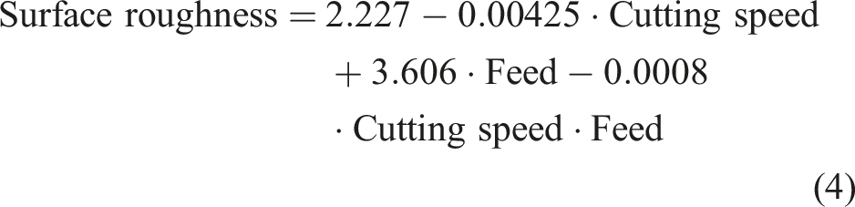
Surface roughness is another performance indicator that is influenced by the drilling process and the variables. Studies have shown that surface roughness increases with axial feed and cutting speed,28,29 with cutting speed having a greater impact than feed rate. 28 A contradictory trend, where surface roughness decrease with the increase in cutting speed increased, was also observed. 10 In all cases, however, surface roughness increases due to uncut fibers and microcracking. Drilling-induced thrust force and temperature also affect the quality of the drilled hole surface, with higher thrust forces contributing to fiber breakout and increased surface roughness.12,16 Microscopic observations have revealed defects such as smeared material, cracking, cavities, and chip adhesion under high thrust loads. 30 Increased cutting temperatures, particularly at higher cutting speeds, have been shown to cause significant damage to the borehole surface layer. 31 The elevated temperatures soften the polymer matrix, forming a recast matrix layer on the machined hole surface.32,33 Due to severe temperatures, conventionally drilled holes in FRPs showed serious microstructural damages in the form of matrix loss and surface cavities. 34
Recent research has focused on the drilling of FMLs, examining the influence of process variables on thrust force, surface quality, and cutting temperature. Axial feed and cutting speed have been found to influence thrust force when drilling GLARE. Thrust force increases drastically with feed rate35–37 but decreases with higher cutting speeds.1,36 Ultrasonic-assisted drilling has been shown to reduce thrust force by up to 65% in GLARE. 38 Tool geometry also affects thrust force, with larger tools producing higher forces. 36 Two-fluted drills have been shown to perform better than three-fluted and eight-faceted drills, delivering zero delamination and minimal burr formation. 39 Cutting temperature tends to rise with increasing cutting speed but decreases with higher axial feed rates. 40 However, temperatures exceeding T g can cause surface damage and matrix pyrolysis, leading to stress concentration and reduced bearing strength.40,41 Surface roughness in FMLs is strongly influenced by process variables. As with FRCs, surface roughness increases with feed rate 1 but decreases with cutting speed. 36 Unoptimized drilling conditions can lead to surface damage. 1 The mismatch between the mechanical and physical properties of the metal and epoxy-reinforced fibers can cause interlaminar failure. At higher feed rates and cutting speeds, issues such as built-up edges, fiber damage, material smearing, and metal-composite debonding have also been reported.42–44
As highlighted, numerous challenges persist in drilling FRCs, and these issues are further compounded when machining hybrid materials like FMLs. High forces and machining temperatures can affect the surface quality of stacked materials. Drilling-induced damage can compromise the reliability, performance, and lifespan of FMLs. While literature discusses drilling studies on GLARE and CFRP, the damage mechanisms encountered when drilling CARALL FMLs are distinct due to variations in material structure, resulting in unique thermo-mechanical characteristics. In contrast to GLARE, which has reduced interlaminar stiffness because of its glass fiber layers, CARALL FMLs contain carbon fibers with a higher modulus. This can cause increased stress concentration and localized heat buildup, necessitating further detailed investigation. In addition, while there are a limited number of studies focused on the drilling of GLARE FML, an in-depth investigation into the machinability and surface quality associated with drilling CARALL FML remains unexplored. In particular, research on the influence of cutting forces and drilling temperatures on hole surface quality in CARALL is scant. Poor hole quality during the assembly stage can lead to part rejection, significantly increasing both costs and production time. Given CARALL’s critical use in defense and aerospace applications, thorough research on its drilling behavior is essential. This study, therefore, investigates the machinability of CARALL FML, with a focus on cutting forces and machining temperatures. Further, the influence of cutting forces and temperature on hole surface roughness and surface damage will be explored. Strategies to minimize surface defects, such as tearing, fiber pullout, delamination, and debonding, will also be identified.
Materials and methods
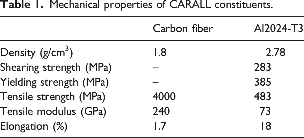
Mechanical properties of CARALL constituents.
The stacking order of metallic and prepreg layers in CARALL specimens is shown in Figure 1(a). For the fabrication of the CARALL specimens, vacuum bagging with the autoclave curing method was considered. After the assembly, specimens were vacuum bagged (−0.5 bar) and autoclave cured (see Figure 1(b)). The specimens were cured by initially heating to 90°C by increasing the temperature at a rate of 2°C/min. Following an isothermal dwelling of 30 min, the temperature was raised to 120°C at a rate of 1.5°C/min and maintained for a dwell period of 60 min. At the end, specimens were cooled to 30°C at a rate of 3°C/min. Figure 1(c) shows the curing cycle used to cure the specimens in the autoclave, while Figure 1(d) shows the fabricated CARALL specimen. Manufacturing of the hybrid material showing: (a) CARALL stacking sequence, (b) Autoclave-based vacuum bagging setup, (c) Autoclave curing cycle employed, and (d) CARALL specimen after demoulding.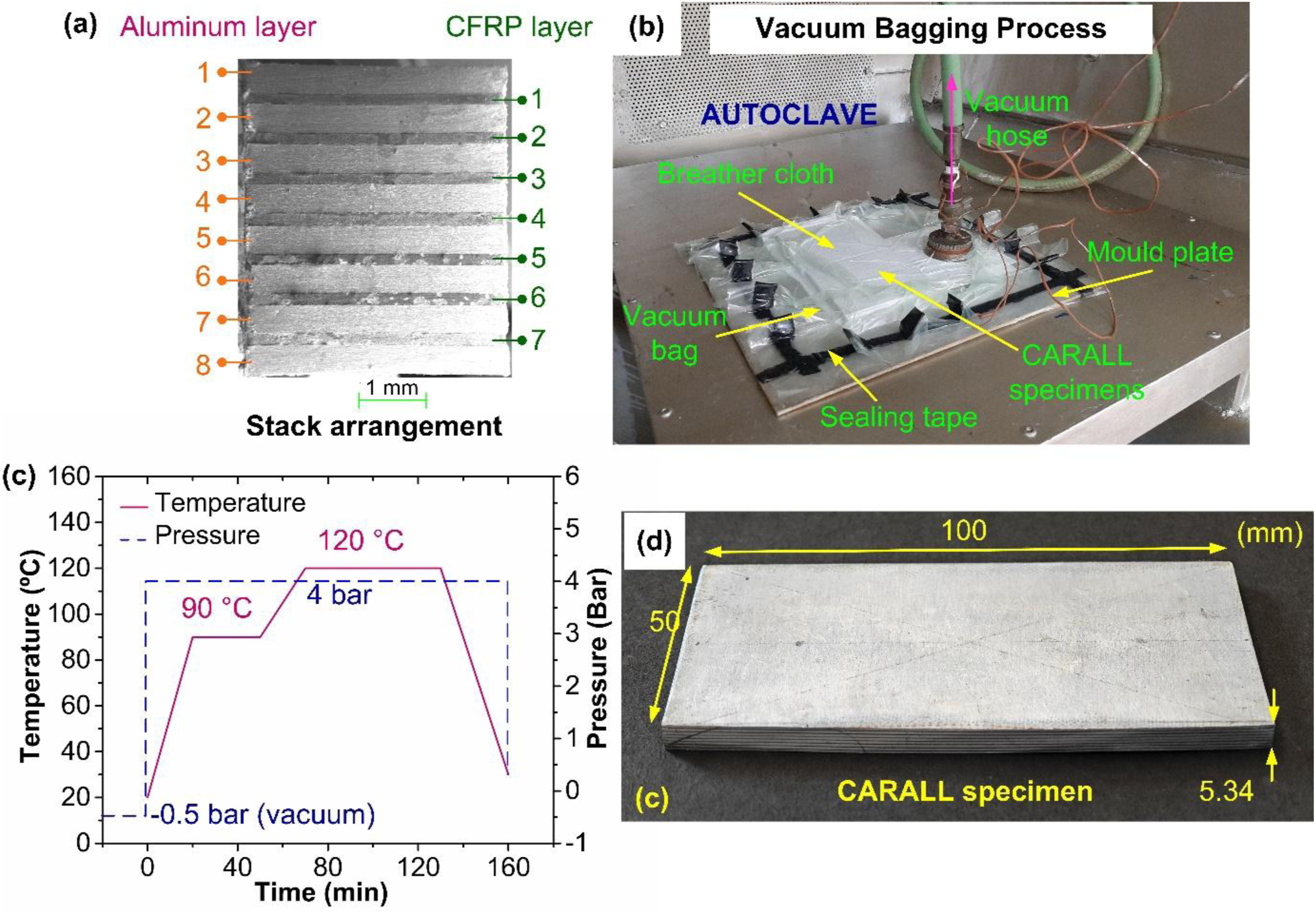
Figure 2(a) displays the experimental setup on the CNC vertical machining center (AMS Spark) employed to perform the drilling experiments. The mechanical properties and geometry of the drilling tool influence the cutting forces, surface roughness, and damage caused by drilling composite materials. According to the literature, point angle is a very influential geometric parameter influencing surface quality and damage. A higher point angle can help lower the thrust load and minimize the hole exit damage and delamination when drilling composite materials.46,47 Besides, the size of holes made in materials like FMLs, usually used in aircraft industries, ranges between 5 and 10 mm.1,48 Therefore, considering the past literature, a TiAlN-coated solid carbide twist drill of 6.8 mm diameter, point angle of 140°, and 45° helix angle was used for the experiments (see Figure 2(b)). The cutting tool was changed after drilling three holes to mitigate the effects of tool wear associated with the machining of composites. (a) Drilling experimental setup, (b) Coated twist drill with specifications.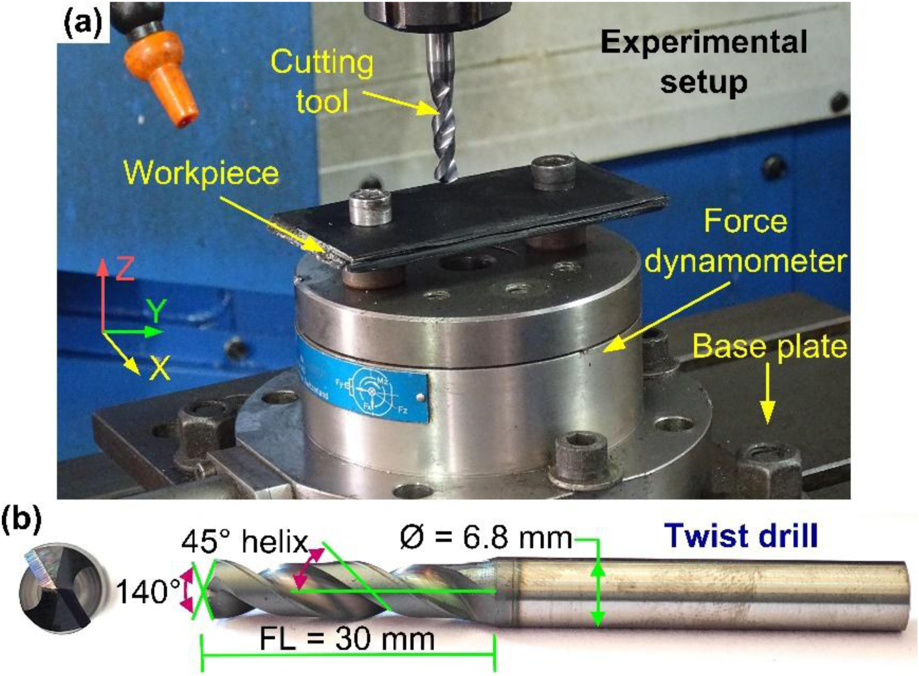
Research on drilling CARALL FMLs is scarce. Initial experiments were conducted using conventional drilling methods, as referenced in existing literature. Further information about the pilot study is available in the literature. 43 It was observed that higher cutting speeds of 85 m/min resulted in lower cutting forces and a relatively good surface finish. According to previous studies, very high cutting speeds can increase the cutting temperature above the glass transition temperature of the epoxy, leading to thermal degradation. In contrast, using feed rates as high as 0.4 mm/rev led to significant thrust force, causing large burrs, delamination, and surface damage.49,50 Additionally, it was possible to keep the machining temperature below the glass transition temperature by using a low cutting speed (20 m/min) combined while maintaining the feed well below 0.3 mm/rev. The cutting speed was also chosen based on the machine tool’s limitations. The experiments were performed on a vertical machine center (VMC) with a maximum spindle speed of 6000 rev/min. However, the maximum level of spindle speed for the experiments was restricted to 75% of the maximum machine spindle speed (4500 rev/min). Given a drill diameter of 6.8 mm, the highest cutting speed feasible for the machining trials was 95 m/min. Overall, it was observed that both cutting speed and axial feed had a significant impact on cutting forces, surface roughness, and machining temperature. Since the present study aims improve the surface finish and limit surface damage while drilling the CARALL FML, the decision was made to examine the effects of both cutting speed and axial feed on process performance, with drilling experiments planned using two control factors, cutting speed and axial feed, at three levels. Accordingly, the experiments were performed by choosing three cutting speed levels (V c ) of 30, 60, and 90 m/min and three axial feed rates (f a ) of 0.05, 0.15, and 0.25 mm/rev. A total of nine drilling trials were carried out, and each trial was repeated thrice to ensure robust and reliable performance data. The drilling experiments were conducted without utilizing coolant, in line with the principles of sustainable manufacturing. Moreover, the statistical application MINITAB 17 was utilized to execute an Analysis of Variance (ANOVA), highlighting the influence and relevance of the process parameters on the response variables. In this analysis, a variable was identified as significant if its P-value was less than 0.05, reflecting a 95% confidence level.
Cutting forces and machining temperature were considered as the performance measures to evaluate the machinability of CARALL FML. Cutting force measurement was accomplished by employing a four-component piezoelectric dynamometer (Kistler 9272B) having a maximum measurement range of ±5 kN, while the force signals were conditioned using a charge amplifier (Kistler 5070A) (see Figure 3(a)). The two cutting force components (Thrust force and Torque) were measured based on the dynamometer-specified reference system. For the thrust force, the measurement range was set at ±2 kN, whereas for the measurement of drilling torque, a measurement range of ±1.5 Nm was selected. The cutting force data was acquired for 45 s at a sampling rate of 2000 Hz and further processed and analyzed using Dynoware software (Type 2825D-02). (a) Cutting force measurement setup, (b) Machining temperature measurement, (c) Surface roughness measurement setup, (d) Roughness measurement positions, (e) SEM/EDS system.
In order to measure the machining temperature, an infrared (IR) camera (Fluke Ti32) with a 20°C to 600°C measuring range and ±2°C measurement accuracy was utilized (see Figure 3(b)). The IR camera was calibrated to minimize the difference in color and, thus, the thermal emissivity between the aluminum and CFRP. The work specimen coated in matte black paint was placed in an oven, and the surface temperature was recorded using the thermocouple and the IR camera. Accordingly, a thermal emissivity of 0.95 was determined. The distance between the work specimen and the IR camera was 0.1 m, and a constant focus was maintained on the work specimen during the entire hole-drilling operation. An average of three readings were considered during the evaluation.
The surface roughness of the drilled holes was measured offline, i.e., after the completion of drilling experiments. Average surface roughness (Ra) data was gathered according to ISO 4287 using a contact-type surface measurement tester (Taylor Hobson – Form Talysurf 50) with a standard conical diamond-type stylus with a tip radius of 2.5 μm (see Figure 3(c)). The measurements were made by positioning the work specimen on the granite base constructed on anti-vibration mounts. A 2CR-type filter was chosen for surface roughness analysis. The readings were made considering a 3 mm evaluation length, while the filter cut-off was set at 0.8 mm and the scan speed at 0.5 mm/s. The roughness measurements were made at four equidistant locations, and the average of the readings was considered. The measurement positions and directions are also illustrated using Figure 3(d). Additionally, characterization of the hole surface was performed with a scanning electron microscope (SEM) (Carl Zeiss EVO MA18), as seen in Figure 3(e).
Results and discussion
Cutting force analysis
Thrust force (F z ) and torque (M z ) are crucial responses that can affect the functionality of CARALL FMLs. Intense cutting forces can affect surface finish, burr size, and dimensional accuracy of drilled holes. 51 Additionally, extreme loading conditions can lead to fiber breakage and stack delamination, significantly undermining the mechanical reliability and service life of CARALL FMLs. Given this criticality, the present study focuses on evaluating cutting forces during the drilling process.
Figure 4 presents the thrust force profile recorded during the drilling of CARALL FML, illustrating a varying trend. A noticeable difference in force magnitude is observed when transitioning between aluminum and carbon fiber prepreg layers. Peaks 1-8 represent higher thrust forces when machining the metal layers, while Peaks A-G correspond to the lower forces encountered during the drilling of carbon fiber prepreg layers. The torque also shows a similar profile when drilling CARALL FML. The higher cutting force magnitude when machining aluminum layers is attributed to the greater resistance offered by the metallic layers to deformation. In contrast, lower forces while drilling carbon fiber layers are ascribed to brittle failure experienced by the matrix in the form of matrix cracking and fiber breakage. Raw thrust force and torque profiles obtained during drilling.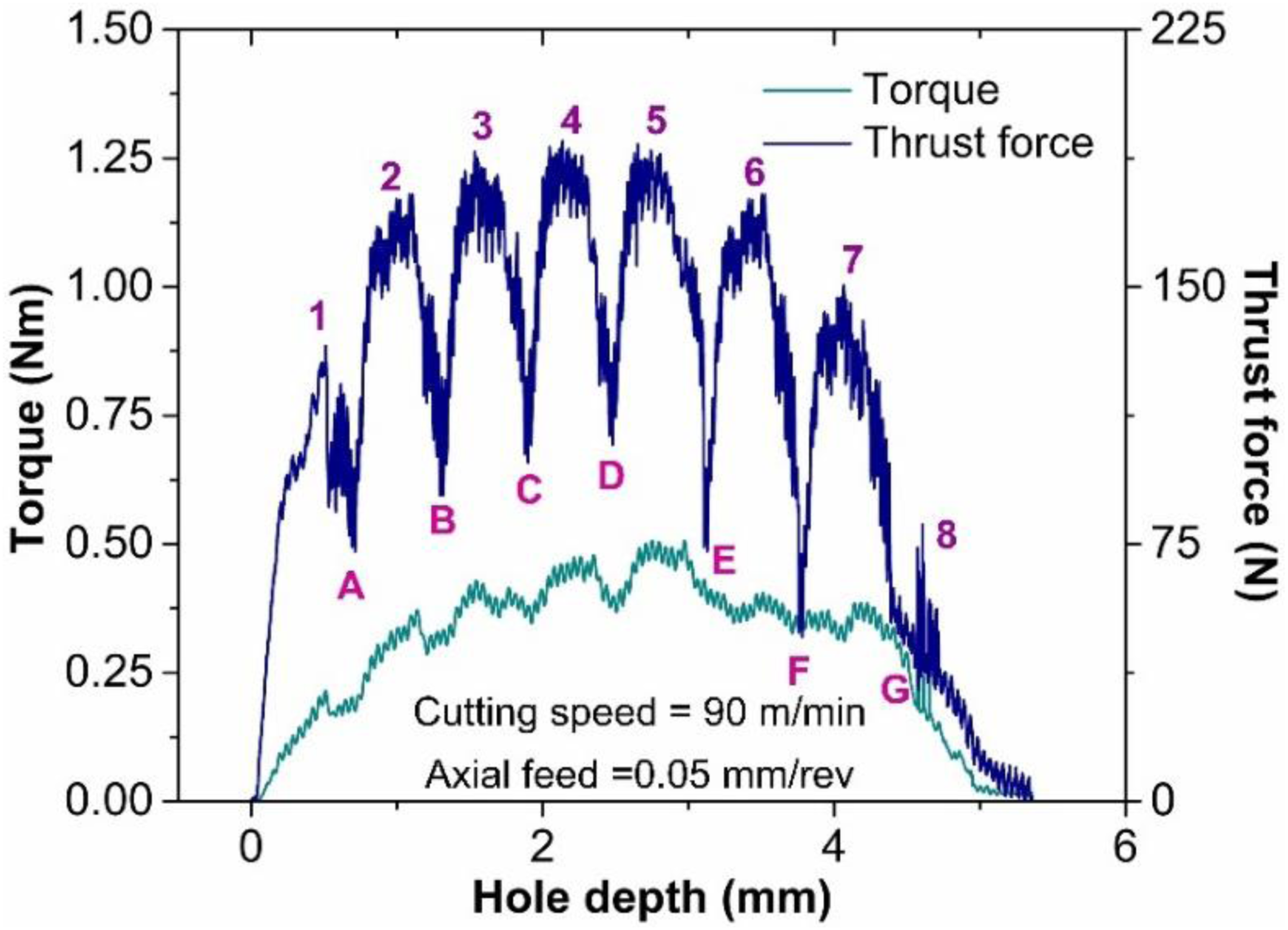
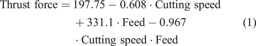
Figure 5(a) exhibits the effect of cutting speed on thrust force. It decreased as cutting speed increased. The average force recorded for a feed of 0.05 mm/rev was 192.9 N when a 30 m/min cutting speed was employed. With 60 m/min of cutting speed, the average force decreased to 181.1 N, indicating a 6.1% reduction. Thrust force finally dropped to 150.4 N when speed increased to 90 m/min, showing a further 17% drop in force magnitude. Similar speed versus force trends were observed when the cutting was performed with the other two axial feed levels. (a) Influence of process variables on thrust force (b) Influence of process variables on torque.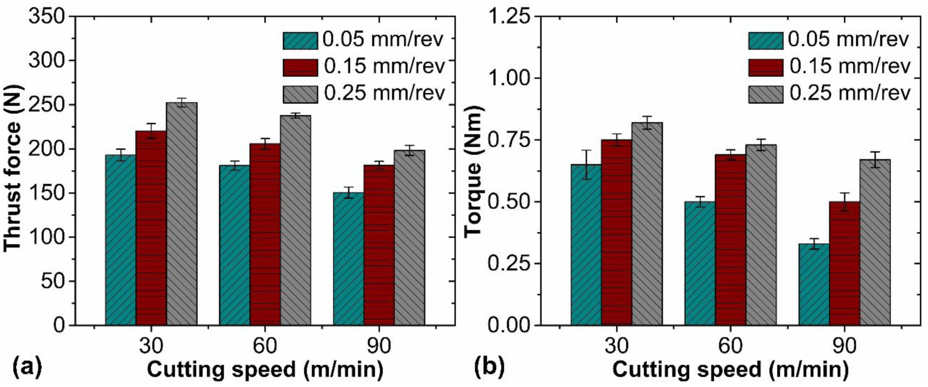
CARALL FML consists of aluminum alloy and CFRP as constituent materials. It is well-known that material shearing during metal cutting causes the metallic aluminum to undergo plastic deformation, which results in the liberation of energy in the form of heat. Moreover, the rate of material plastically deforming increases with cutting speed. The resulting high temperature lowers the yield strength, easing the material shearing phenomenon and reducing the thrust load during metal cutting. Additionally, the heat generated while shearing the aluminum material causes the polymer resin to soften thermally, lowering the force value.
ANOVA for thrust force.
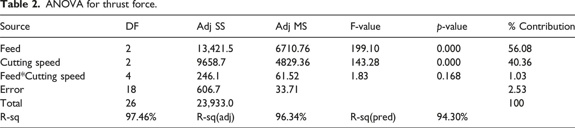
Figure 5(b) illustrates the torque behavior as a function of cutting speed. The results show a clear inverse relationship between torque and cutting speed. At a feed rate of 0.05 mm/rev and a cutting speed of 30 m/min, the torque was measured at 0.65 Nm. When the speed increased to 60 m/min, the torque dropped to 0.51 Nm, reflecting a reduction of 21.5%. A further increase in speed to 90 m/min resulted in a torque decrease to 0.33 Nm, marking an additional reduction of 35.3%. The torque decreased by 49.2% as the cutting speed increased from 30 m/min to 90 m/min. This significant reduction in torque at higher speeds can be attributed to elevated machining temperatures and the associated thermal softening of the material. These results are consistent with the findings reported by Devi et al. 52 and Boughdiri et al. 36 Boughdiri et al. reported an 80% increase in force for a rise in the axial feed from 0.02 to 0.3 mm/rev, while drilling GLARE FMLs. 36 Compared to GLARE, CARALL FMLs have a lesser impact on cutting forces, where a 14.6% was observed for a 0.1 mm/rev rise in axial feed.
Additionally, Figure 5(b) presents the torque variation with respect to axial feed. At a fixed cutting speed of 30 m/min, the torque was recorded at 0.65 Nm with a feed of 0.05 mm/rev. As the feed increased to 0.15 mm/rev, the torque rose to 0.75 Nm, reflecting a 15.4% increase. Further increasing the feed to 0.25 mm/rev resulted in a torque of 0.82 Nm, marking an additional 9.3% increase. The torque increased by 26.15% as the feed rate increased from 0.05 mm/rev to 0.25 mm/rev. In metal cutting, the work-tool contact area and the corresponding machining load increase with axial feed; therefore, the torque also increases proportionately. The comparable relationship between the cutting forces and axial feeds was reported while drilling GLARE FMLs by Giasin et al., 1 where an increase in the axial feed values augmented the cutting resistance offered due to increased plastic deformation of aluminium layers. The elevated cutting resistance at higher axial feed values increased the machining load on the tool.
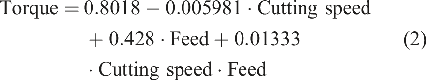
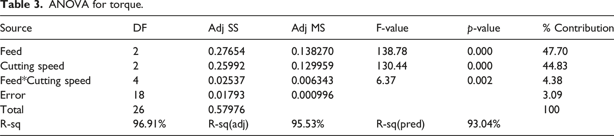
ANOVA for torque.
Machining temperature analysis
Evaluating the machining temperature (T m ) generated during the drilling of FMLs is critical, as elevated temperatures can degrade the mechanical properties of the matrix resin and lead to thermal damage. Higher temperatures can also result in matrix smearing, delamination, fiber pullout, severe tool wear, and unsatisfactory surface finish.53,54
Figure 6 shows the IR thermographs obtained at different stages of drilling in CARALL specimen machined with 60 m/min speed and 0.05 mm/rev feed. The progression of machining temperature during the drilling cycle can be segregated into three phases. During the initial contact, the lip of the drill interacts with the workpiece (See Figure 6(a)). Due to interaction, the metallic material is deformed plastically and eventually undergoes ductile failure. In due process, heat is generated. However, temperature is maintained at moderate levels during the initial interaction. With the further advancement of the tool, the end-cutting edges are entirely engaged in machining the laminate. Considering full interaction and heat accumulation, the temperature rises drastically and reaches the maximum value (See Figure 6(b)). Finally, as the drill bit exits the drilled hole, the temperature decreases due to the convective air cooling and effective heat dissipation from the work-tool system (see Figure 6(c)). Machining temperature at different stages of hole drilling with cutting speed = 60 m/min and feed = 0.05 mm/rev.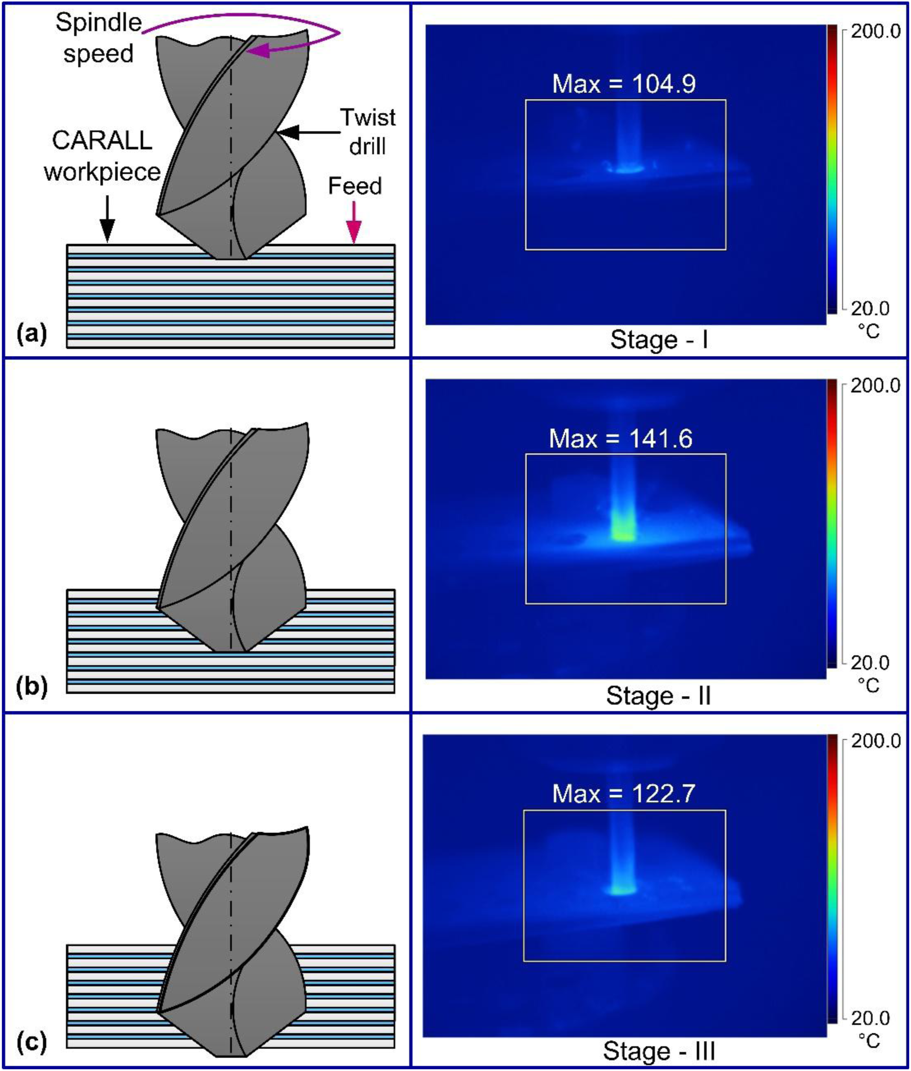
Figure 7 displays the evolution of the machining temperature at different cutting speeds. Temperature developed while drilling CARALL increased with the cutting speed. When drilling at a feed of 0.05 mm/rev, an average temperature of 118.2°C was recorded when a 30 m/min speed was selected. At 60 m/min, the average temperature increased to 141.5°C. Finally, at 90 m/min, the average temperature rose to 169.1°C. As cutting speed increased from the lowest to the highest level, temperature increased by about 30%. Figure 8(a)-(c), which exhibit the machining temperature cartography, verify the trend. Similar trends were observed at other axial feed values. The strain rate at the shear zone is very high when the material is cut with higher cutting speeds. Consequently, heat energy increases, thereby resulting in a higher temperature. Also, with higher cutting speeds, the heat dissipation rate decreases, thus increasing the temperature magnitude. Machining temperature response with process variables. Cartographies of the machining temperature when drilling is conducted with a feed rate of 0.05 mm/rev and: (a) 30 m/min cutting speed, (b) 60 m/min cutting speed, and (c) 90 m/min cutting speed.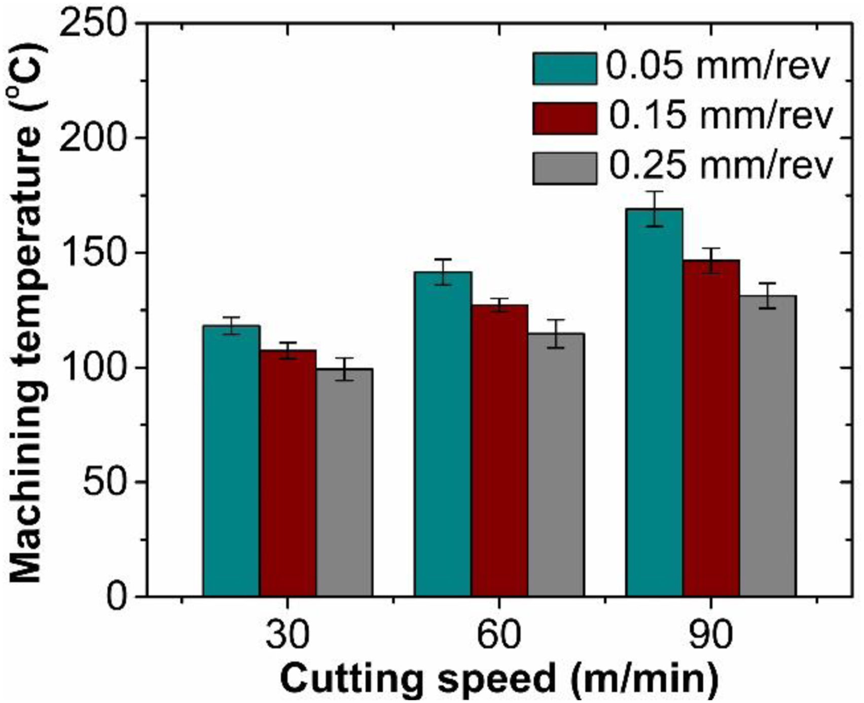
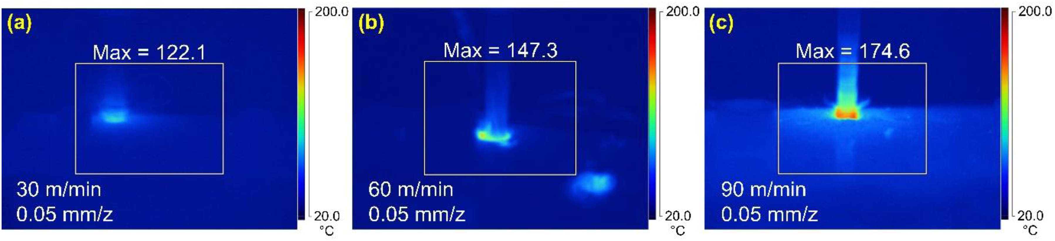
Figure 7 also displays the temperature variation with axial feed. The trend reveals the positive impact of feed on temperature, such that temperature magnitude is reduced as axial feed increases. When drilling at a 30 m/min speed, an average temperature of 118.7°C was recorded when a feed speed of 0.05 mm/rev was selected. At a higher feed of 0.15 mm/rev, the temperature was reduced to 107.3°C. The measured temperature decreased to 99.23°C when a 0.25 mm/rev feed was chosen. Accordingly, temperature reduced by 16.4% as feed increased from 0.05 mm/rev to 0.25 mm/rev. Figure 9(a)-(c), which exhibit the machining temperature cartography, verify the decreasing trend. A fall in the temperature magnitude at higher feed is linked to the material removal rate. Faster chip evacuation at higher feed lowers the work-tool contact time. Additionally, improved chip breakability at higher feeds reduces contact friction, helping to smoothen chip evacuation and thus lowering machining temperature. The observed temperature versus feed trend agrees with observations made while drilling CFRP by Brinksmeier et al.
31
and Zitoune et al.,
55
where a similar decrease in the temperature magnitude was observed with an increase in the axial feeds. Cartographies of the machining temperature when drilling is conducted with a cutting speed of 30 m/min and with: (a) 0.05 mm/rev feed rate, (b) 0.15 mm/rev feed rate, and (c) 0.25 mm/rev feed rate.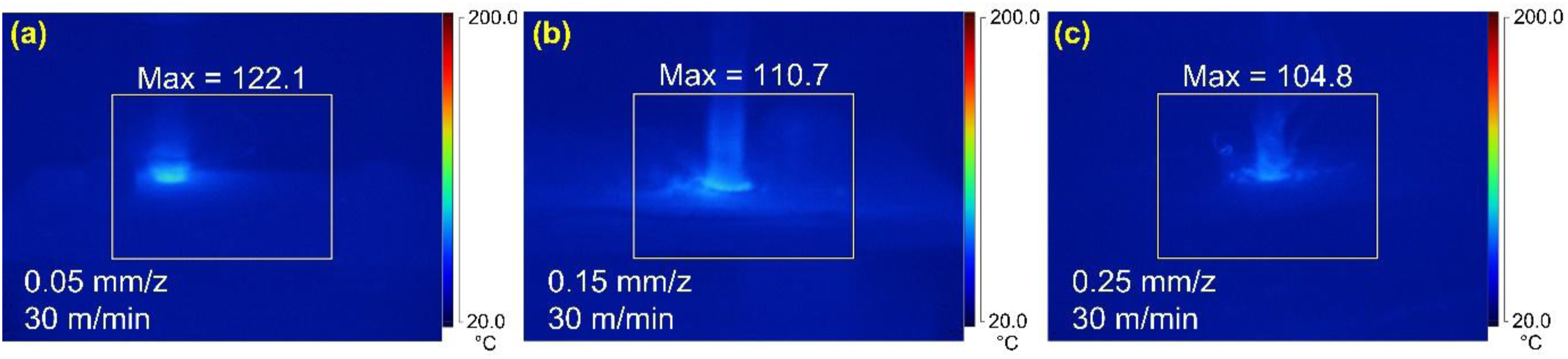
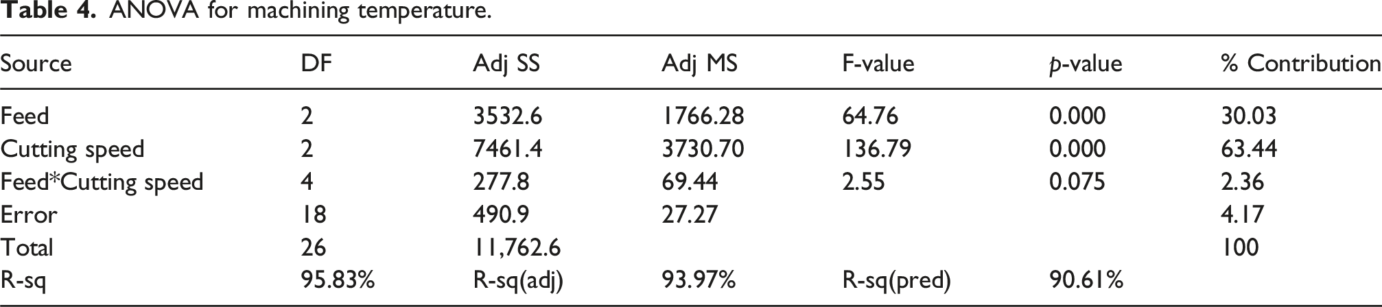
ANOVA for machining temperature.
Assessment of hole surface quality
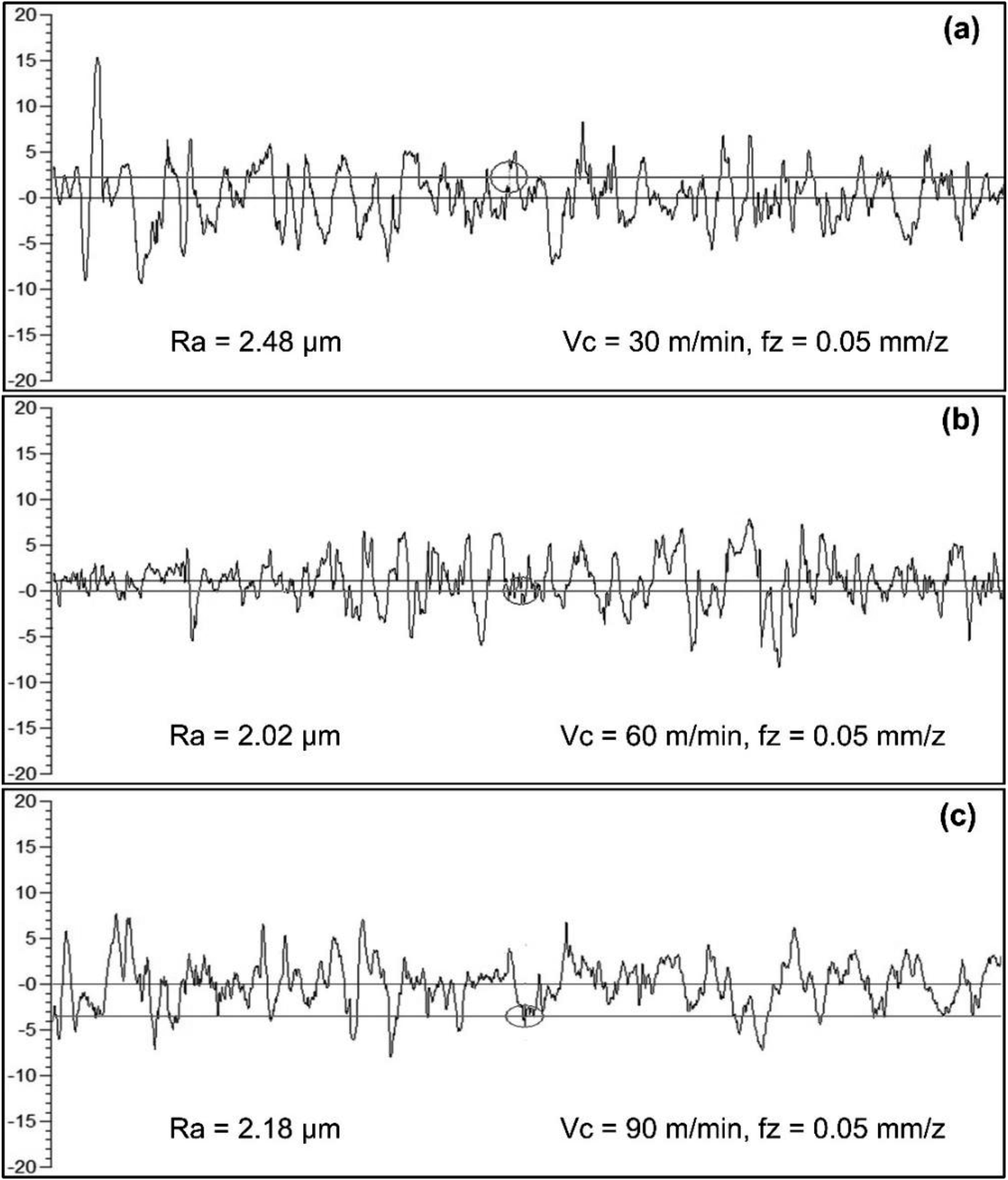
The quality of drilled holes was investigated, considering its influence on the service life and functionality of the FMLs. Figure 10(a) displays the evolution of surface roughness with cutting speed. The surface roughness decreased as the cutting speed increased from 30 m/min to 60 m/min and increased as the speed increased to 90 m/min. For instance, an average roughness of 2.39 µm was measured in the hole drilled with a 30 m/min speed and feed of 0.05 mm/rev. Average roughness reduced to 1.93 µm when the machining was performed at 60 m/min, indicating a 19.2% reduction. At a 90 m/min speed, average roughness increased to 2.11 µm, marking a 9.3% increase in the measured surface roughness. The decrease in roughness magnitude with the cutting speed increment can be verified from the surface roughness profiles displayed in Figure 11. Similar surface roughness versus cutting speed trends were observed with other feed values. Surface roughness response with process variables. Surface roughness profiles from holes when drilling is conducted with a feed rate of 0.05 mm/rev and with: (a) 30 m/min cutting speed, (b) 60 m/min cutting speed, and (c) 90 m/min cutting speed.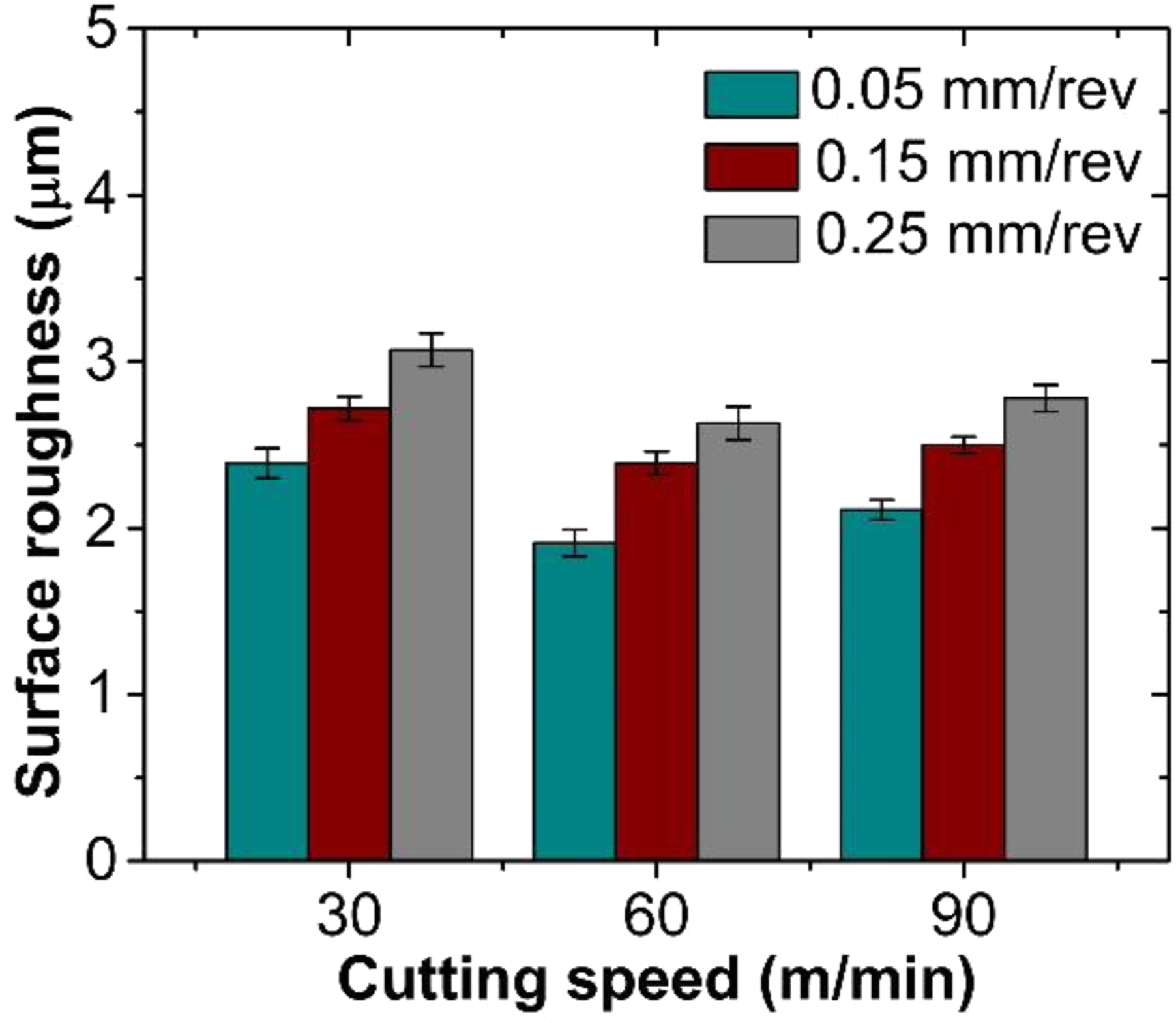
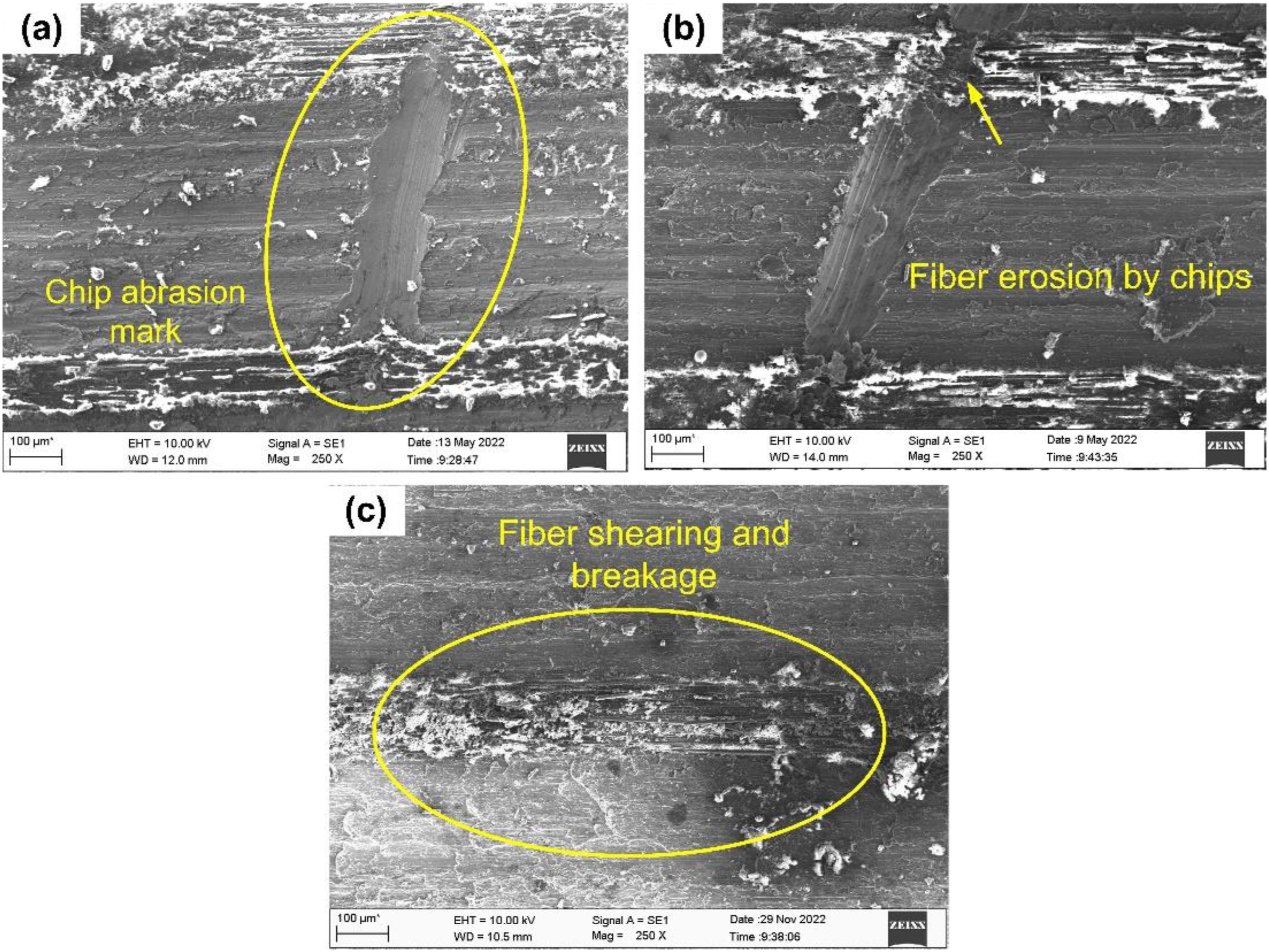
Higher roughness at a lower speed of 30 m/min can be ascribed to the built-up edge (BUE) formation (see Figure 12(a)). The BUEs adversely affected the cutting operation, thereby deteriorating the surface quality. In addition, the continuous chips produced at lower feed and speed combination also affected the surface quality at lower cutting speeds (Figure 12(b), (c)). The strain-hardened chips get entangled around the twist drill and abrade the bore surface, producing deep grooves (see Figure 13(a)) and degrading the surface finish. Moreover, lengthy chips also interact with the softer carbon fiber prepreg, resulting in material erosion (see Figure 13(b)). Additionally, higher thrust force generated due to the selection of lower cutting speed resulted in fiber shearing and breakage, as seen in Figure 13(c). Similar observations were reported when drilling GLARE FML.
43
(a) Chip entanglement around the tool, (b) Built-up edge on tool, (c) Long continuous chip formation during drilling. Surface of the hole machined at 30 m/min showing: (a) Chip abrasion marks, (b) Fiber erosion, and (c) Fiber shearing and breakage.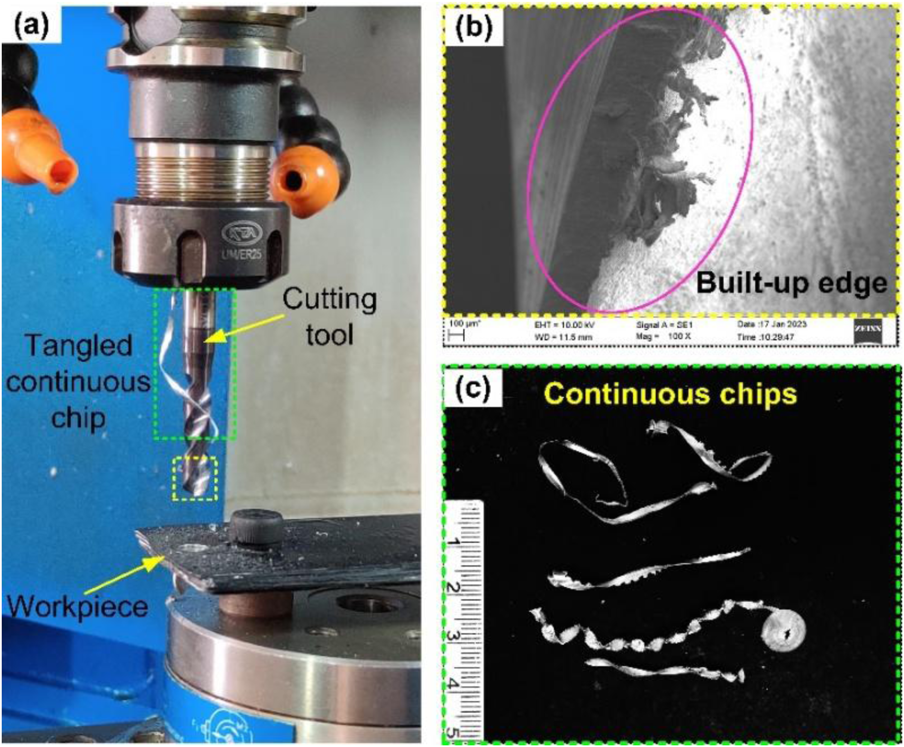
As discussed, the surface roughness decreased when a 60 m/min cutting speed was employed to drill the holes. The reduction in roughness magnitude in holes machined at 60 m/min is attributed to matrix smearing. The machining temperature developed when drilling at a 60 m/min speed was sufficient to soften the resin material. The softened matrix material is smeared against the hole wall, thus covering the fiber bundles and improving the surface finish (see Figure 14(a)). Some form of resin loss with partial exposure of fiber layers was also witnessed, as depicted in Figure 14(b). Resin loss can result from the high temperature noted at the utilized cutting speed. Also, the tendency to form BUEs is reduced at higher cutting speeds, thus producing a clean surface, as seen in Figure 14(c). Surface of the hole machined at 60 m/min showing: (a) Resin material smearing, (b) Partial fiber exposure, and (c) Damage free surface.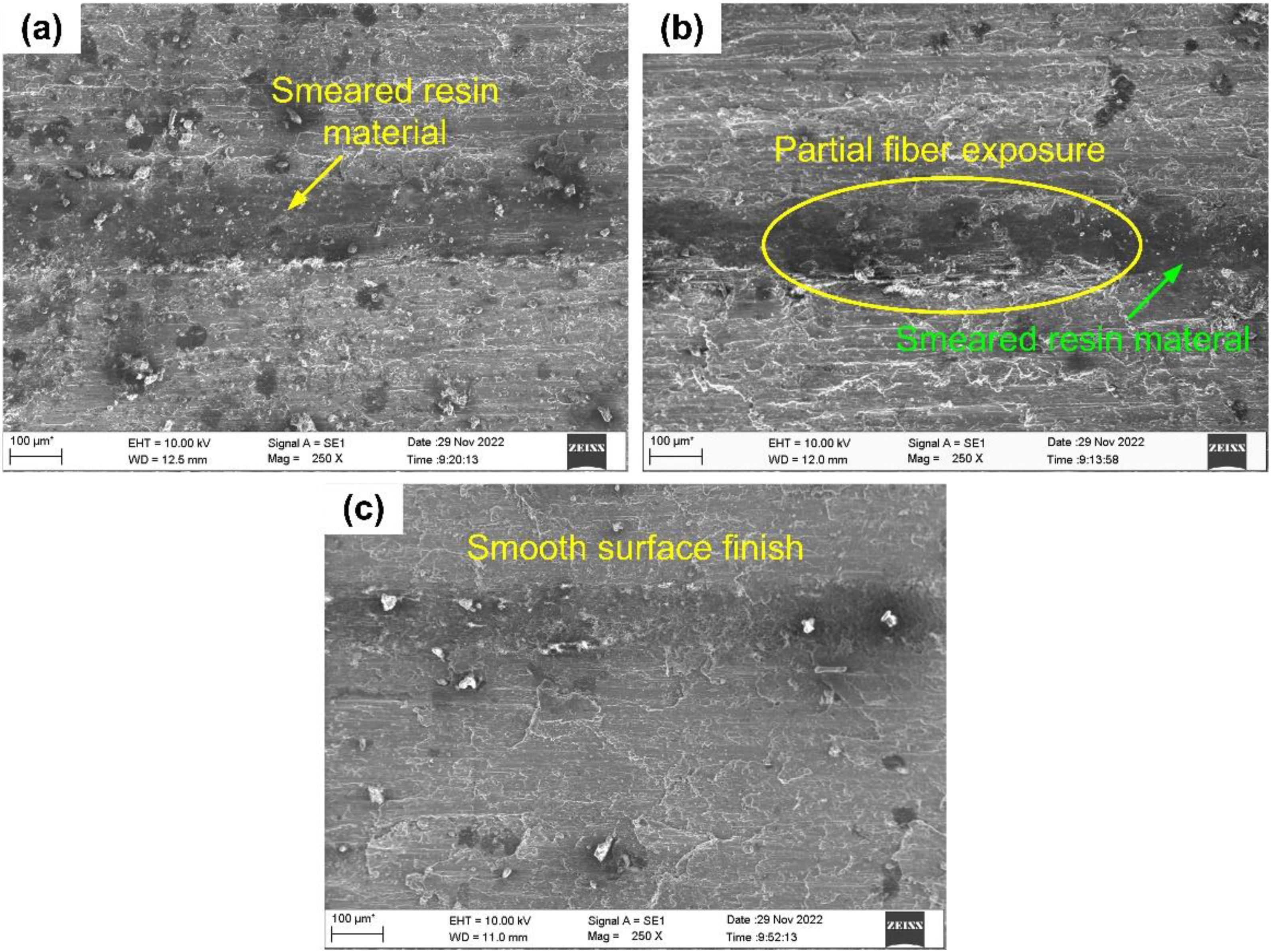
An increase in surface roughness was reported at a higher cutting speed of 90 m/min. Metallic material underwent significant plastic deformation at a higher speed (90 m/min), producing excessive heat. The material in the plastic state was smeared across the machined metallic surface, deteriorating the surface finish, as seen in Figure 15(a). The matrix resin showed signs of degradation due to the higher machining temperature (greater than T
g
). Excessive heat lowered the fiber-resin bond strength, resulting in the loss of the softened matrix, thereby exposing the fibers (see Figure 15(b)). Loss of resin strength resulted in fiber separation and pullout, as evident from Figure 15(c). Additionally, plastic deformation of aluminum material resulted in material ingression and interlayer burrs, as seen in Figure 15(d). Surface of the hole machined at 90 m/min showing: (a) Metallic material smearing, (b) Matrix degradation, (c) Fiber pullout, and (d) Waste material ingression and interlayer burr.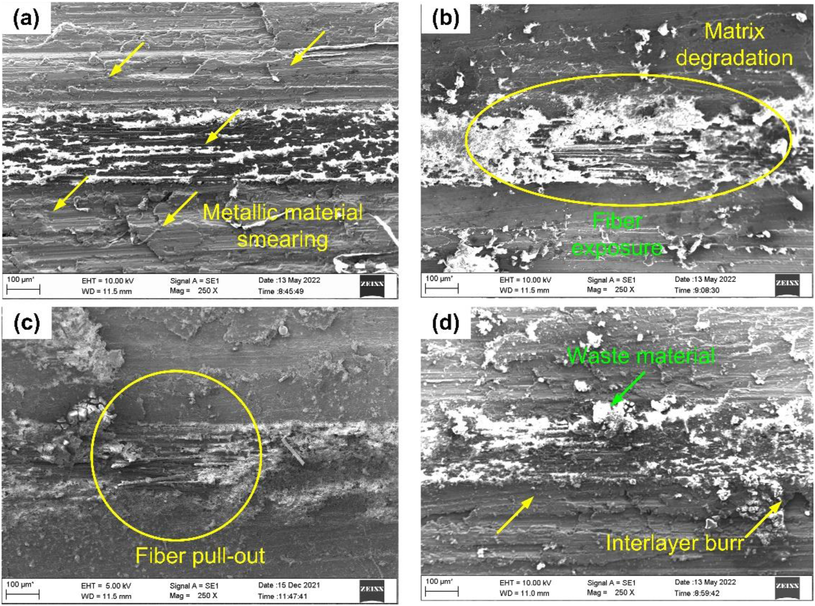
Figure 10 presents the evolution of average roughness with axial feed when drilling CARALL FML. The average roughness increased as feed increased. For instance, for a 30 m/min fixed speed, an average roughness of 2.39 µm was measured when a feed of 0.05 mm/rev was selected. At a higher feed of 0.15 mm/rev, average roughness increased to 2.7 µm. Further, roughness increased to 3.07 µm at a feed of 0.25 mm/rev. Axial feed influenced the hole surface, and a 28.45% increase in surface roughness was recorded as feed increased from 0.05 mm/rev to 0.25 mm/rev. An increase in roughness magnitude with increments in the axial feed was verified from the R
a
profiles displayed in Figure 16. Similar surface roughness versus axial feed trends were observed with other cutting speed values. Surface roughness profiles from holes when drilling is conducted with a cutting speed of 30 m/min and with: (a) 0.05 mm/rev feed rate, (b) 0.15 mm/rev feed rate, and (c) 0.25 mm/rev feed rate.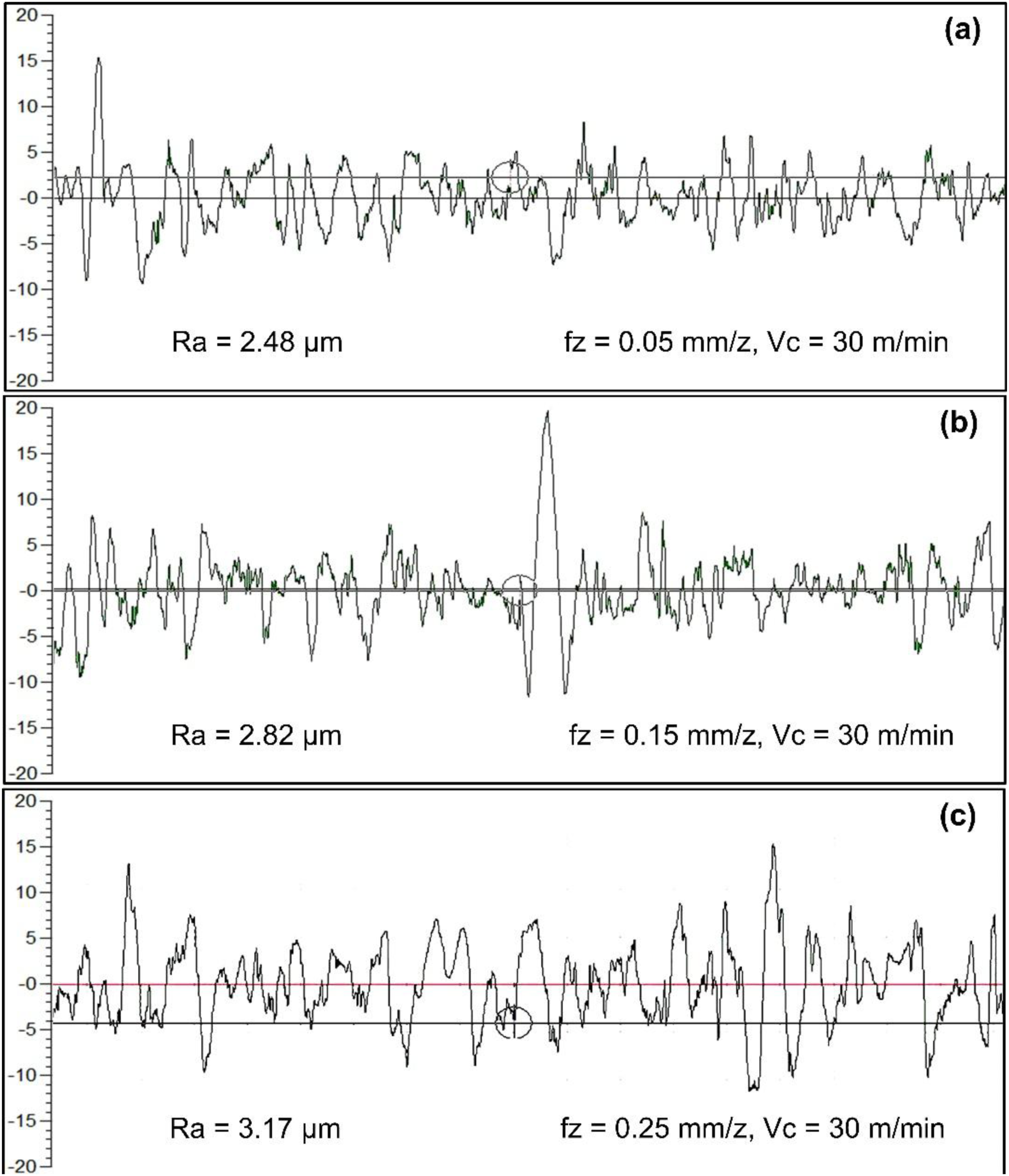
Figure 17(a) exhibits the bore surface generated when feed was maintained at 0.05 mm/rev. Drilling at a lower feed produced feed marks on an aluminum surface. In addition, the hole produced at a lower feed value showed material smearing, as showcased in Figure 17(b). At a feed of 0.05 mm/rev and 90 m/min speed, the recorded temperature of 169.1°C was significantly higher than T
g
of epoxy (T
g
= 130°C). At such temperatures, the matrix softens and becomes viscous and, over a period of time, is re-casted with fibers covered by the thermoplastic matrix resin. This helped in masking any surface damage and improving the surface quality. Overall, the hole surface was intact, with a clean-cut surface and negligible matrix loss. Surface of the hole machined at 0.05 mm/rev showing: (a) Visible feed marks, and (b) Resin matrix smearing.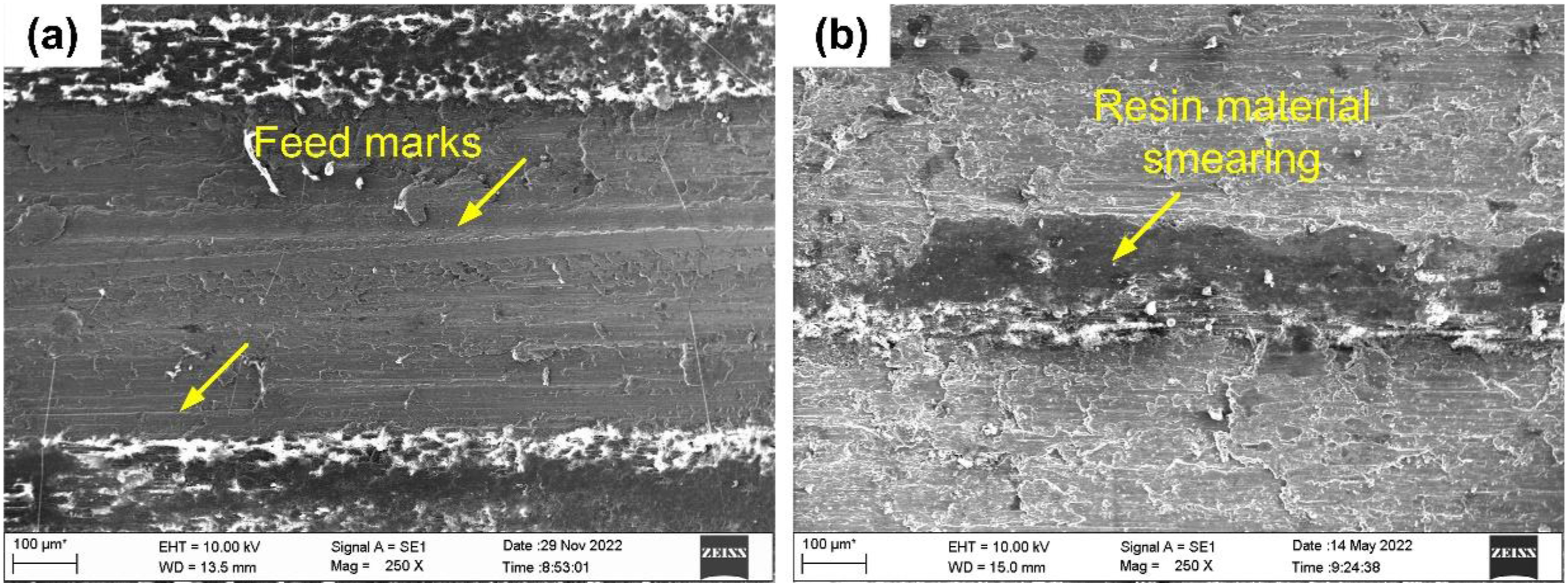
As reported, the surface roughness increased when the feed increased to 0.1 mm/rev. The damage to the CFRP layers increased as feed increased. At higher feeds, thrust force and mechanical damages increased. The resin loss from the prepreg surface resulted in fiber exposure, as seen in Figure 18(a). At some locations, cavities were visible due to the stray fiber pullout (see Figure 18(b)). In addition, fiber bucking and pullout were observed in Figure 18(c). Surface of the hole machined at 0.15 mm/rev showing: (a) Fiber exposure and fiber loss, (b) Cavity formation, and (c) Fiber pullout.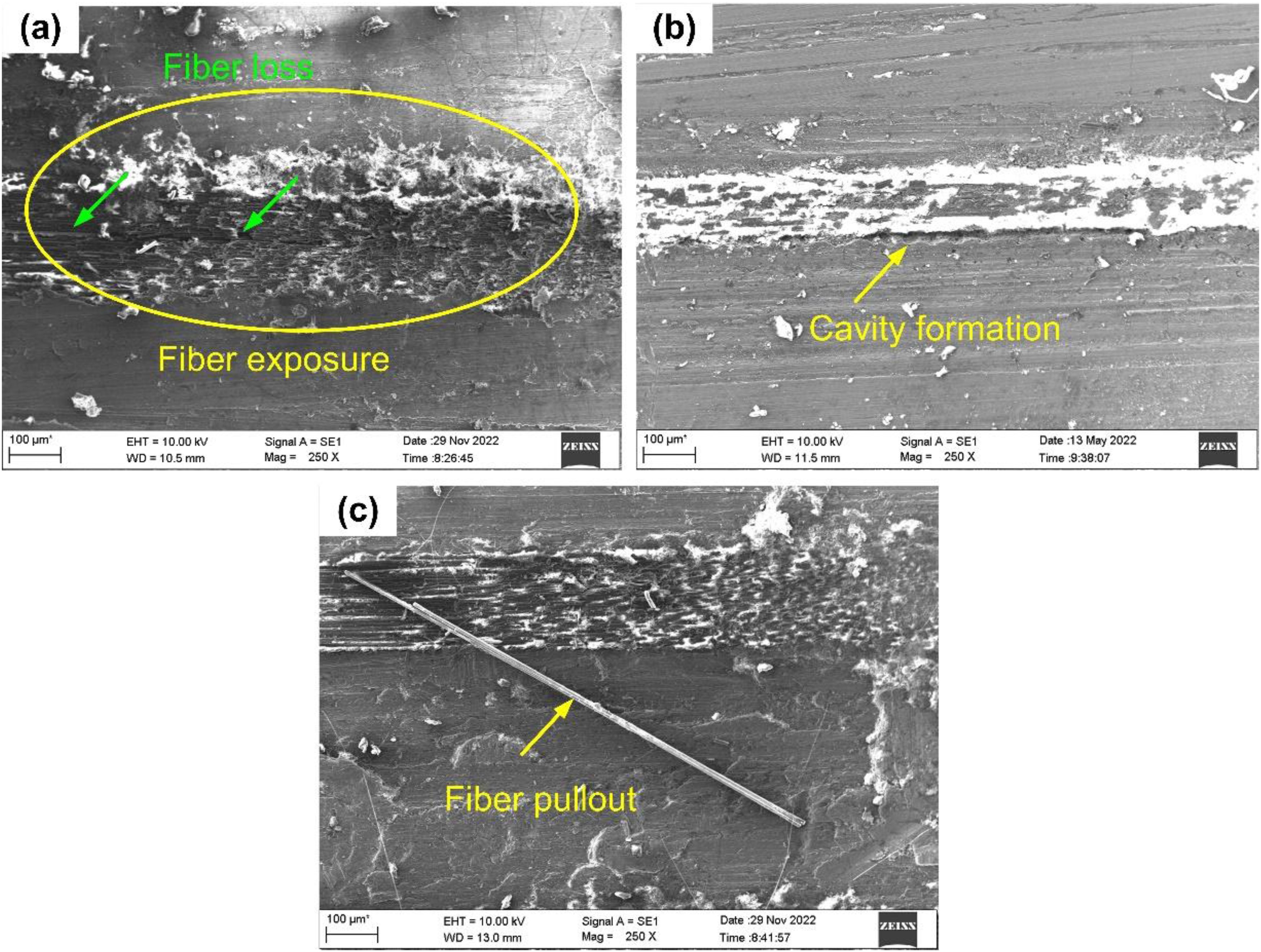
The surface quality further deteriorated in holes drilled at a feed of 0.25 mm/rev. At higher axial feed, uncut chip thickness increased. This increased the thickness of the machined chips. The strain-hardened chips abraded the hole surface, generating deep grooves (see Figure 19(a)), thus deteriorating its quality. Severe matrix loss resulting in surface cavities was noted at higher feed. The matrix loss resulted from removing fibers by bending fracture, as observed in Figure 19(b). As the tool advanced, the fibers in contact with the rake face were subjected to a bending load. The cracks generated due to fiber-bending-induced stress propagate through the subsurface, forming a cavity as the chips are separated from the workpiece. Observations of a similar nature were made by Ge et al.
34
while machining CFRP. Drilling using higher feed also resulted in partial shearing of unidirectional fibers to severe fiber breakage, as seen in Figure 19(c). The hole drilled at higher feed also indicated the presence of adhered debris, as illustrated in Figure 19(d). Surface of the hole machined at 0.25 mm/rev showing: (a) Chip abrasion mark, (b) Fiber exposure and fiber loss, (c) Fiber shearing and breakage, and (d) Material adhesion.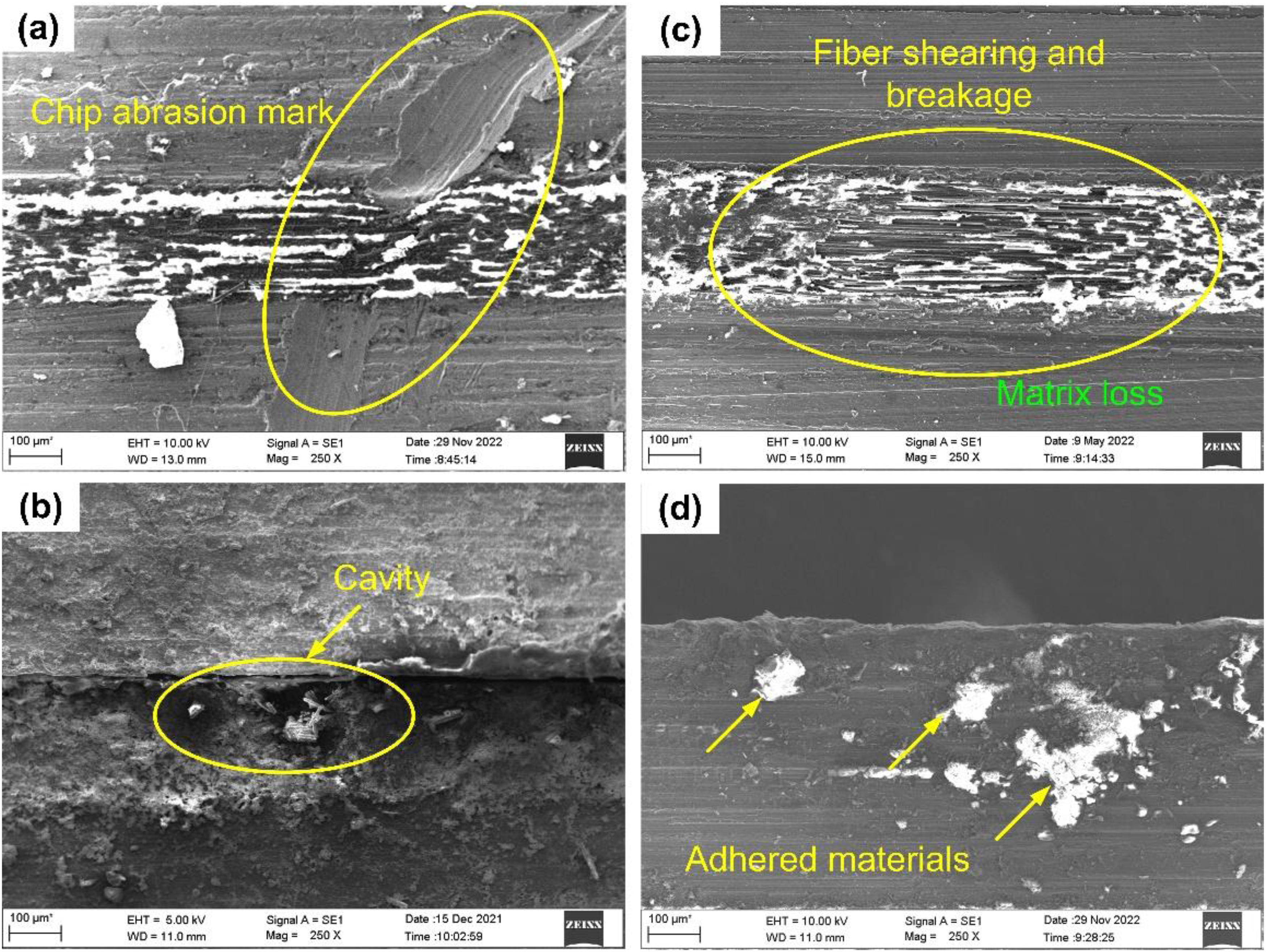
Further characterization revealed the presence of a gap at CFRP and aluminum layer interface near the hole exit, as seen in Figure 20. Delamination was noticed in a hole drilled utilizing a feed of 0.05 mm/rev and 90 m/min cutting speed. The interfacial separation is attributed to the thermal effect prevalent in these cutting conditions. At a feed of 0.05 mm/rev and 90 m/min cutting speed, the recorded machining temperature of 169.1°C was significantly higher than T
g
of epoxy (T
g
= 130°C). At such high temperatures, matrix resin underwent degradation, promoting gap formation. Delamination at metal-CFRP interface in the hole drilled with a feed = 0.05 mm/rev and cutting speed = 90 m/min.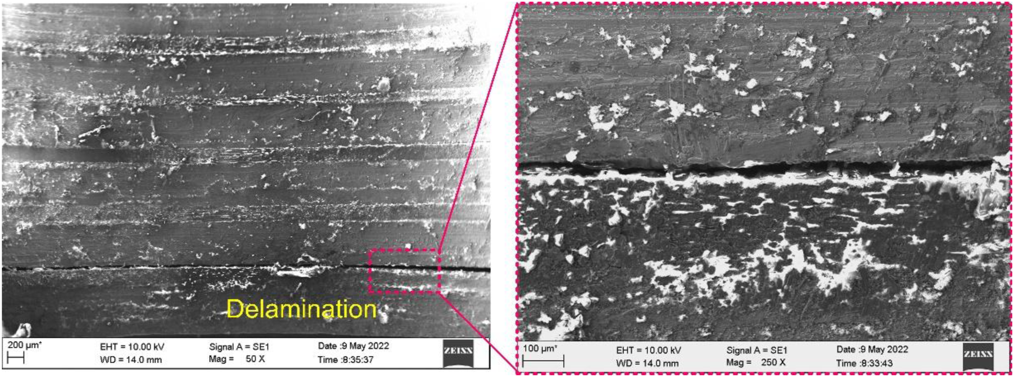
Characterization of the drilled holes showed that the orientation of the fibers also influenced the surface morphology. Figure 21 displays the machined surface topography containing fibers oriented at 0°. Under normal cutting conditions (T
m
< T
g
), when the external load exceeds the bending strength of fibers, brittle fracture occurs, resulting in material removal.
34
The composite material was neatly cut, revealing excellent surface quality, as noted in Figure 21(a). However, with the increase in machining temperatures above T
g
, fibers were exposed due to the loss of severely softened resin material (see Figure 21(b)). Figure 21(c) displays the machined surface morphology where fibers are oriented at 90°. Fibers are subjected to shearing action and undergo brittle failure, thus exposing the fractured surface of the fiber. However, the fibers are covered with resin material. Also, no visible gaps were observed due to the excellent bonding between the fiber and the resin. However, with the increase in cutting temperature, due to fiber flexing and bending, the formation of a gap between the fiber and the resin was detected (see Figure 21(d)). Influence of fiber orientation: (a) 0° orientation – Smeared material, (b) 0° orientation – Fiber exposure and matrix degradation, (c) 90° orientation – Fiber end exposure without any gaps, (d) 90° orientation – Fiber end exposure with gap formation.
The surface morphology was also evaluated considering a fiber orientation of 45°. Figure 22(a) displays machined surface morphology where fibers are oriented at 45°. Fibers are subjected to compression-induced shearing, resulting in fiber cracking. Further, shear fracture of the fiber/matrix interface occurs with the advancement of the cutting tool. Accordingly, the sheared face of the fibers was visible, with fibers still embedded in the epoxy matrix. The machined fiber layer depicted a smooth surface, indicating even and uniform cutting. Figure 22(b) shows the morphology of the machined surface obtained as a result of machining fibers oriented at 135°. The fibers are subjected to shear failure; however, due to the specific orientation of the fibers, the machined surface reveals an irregular surface with protruding fiber ends. The exposed fibers are uneven in length due to fractures occurring at different fiber lengths and elastic recovery. Influence of fiber orientation: (a) 45° orientation – Exposed fiber end with a smoother surface, (b) 135° orientation – Exposed fiber end with an irregular surface.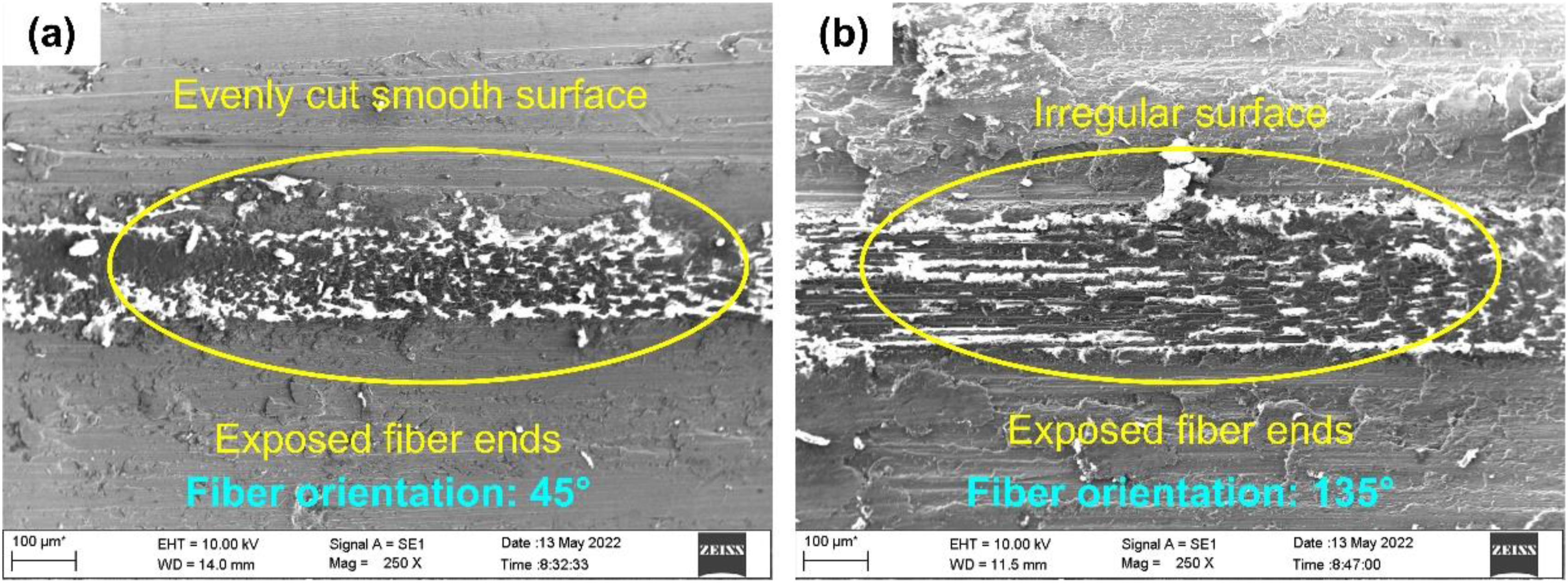
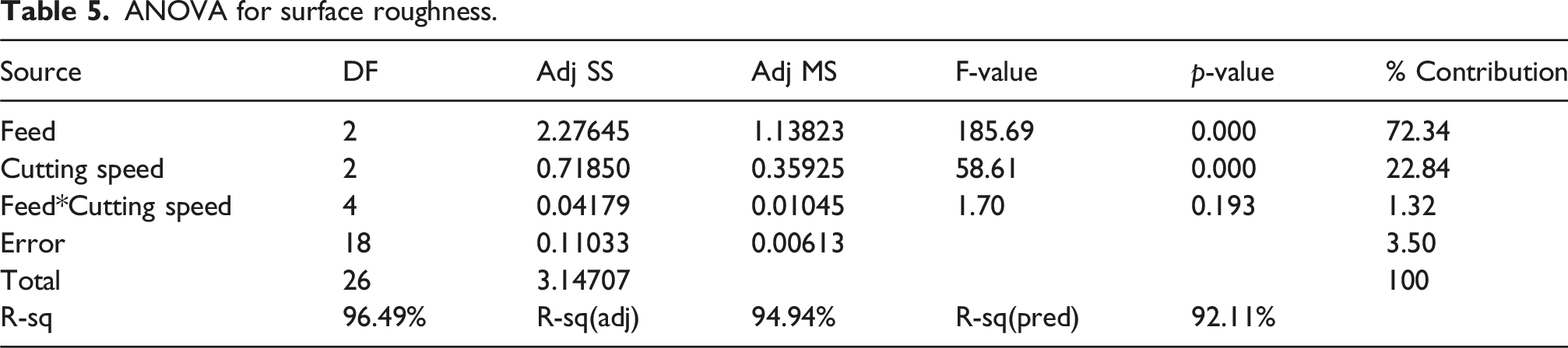
ANOVA for surface roughness.
Conclusions
The present work explored the conventional drilling of CARALL FML under dry conditions, and the following conclusions were derived. (1) Drilling feed and cutting speed influenced the cutting force magnitude (F
z
and M
z
). On average, thrust force and torque increased by 23.8% and 51% as the 0.25 mm/rev axial feed was chosen. However, a 20.3% reduction in thrust force and a 32.4% reduction in torque were noted when the highest level of cutting speed setting was selected (90 m/min). The magnitude of the cutting forces can be lowered by employing a cutting speed of 90 m/min and a feed rate of 0.05 mm/rev, thus reducing the chances of ply delamination. (2) An increase in cutting speed increased the machining temperature, while a reducing trend was observed as the feed increased. The influence of cutting speed on machining temperature was greater than that of axial feed. Machining temperature exceeding glass transition temperature (130°C) was observed when a lower feed (0.05 mm/rev) and higher cutting speed (90 m/min) combination was employed. When cutting speeds increase, the material undergoes thermal softening due to the temperature rise, which leads to a decrease in the magnitude of the cutting force and highlights the interconnected relationship between temperature and cutting force. (3) Surface roughness increased with the feed rate, while a non-linear trend was observed with the increasing cutting speed. A higher cutting speed of 90 m/min and feed rate of 0.25 mm/rev resulted in thermal degradation of the matrix, exposing the fibers and thus increasing roughness. Surface roughness as low as 1.93 µm is achievable by employing a cutting speed of 60 m/min and a lower feed rate of 0.05 mm/rev. (4) Higher cutting forces and machining temperatures significantly damaged the machined hole surface. The selection of a higher feed rate (0.25 mm/rev) resulted in fiber buckling, fiber pullout, and fiber breakage. Choosing a higher cutting speed of 90 m/min led to material smearing, inter-layer burrs, and delamination. This delamination primarily results from the degradation of the matrix at elevated temperatures. Utilization of a higher feed of 0.25 mm/rev and speed of 30 m/min is recommended to avoid thermally induced delamination damage at the ply interface.
The current study comprehensively discusses the impact of cutting parameters on the machining parameters (force and temperature) and the hole quality (roughness and surface quality). The induced defects, such as thermal degradation, inter-layer burrs, and delamination, observed in the current study can alter the mechanical properties of CARALL FMLs. A detailed investigation on post-drilling mechanical attributes is needed to address the after-effects of drilling on bearing and adhesion strength of CARALL FML.
Footnotes
Acknowledgements
The authors would like to acknowledge the Manipal Academy of Higher Education for providing a seed grant to purchase the raw materials and permitting the authors to use the workshop and characterization facilities.
Author contributions
All authors have contributed to the study’s conception and design. Material preparation, data collection, and analysis were performed by Gururaj Bolar and Madhusudhan Balkundhi. The first draft of the manuscript was written by Gururaj Bolar and Satish Shenoy Baloor. Review and editing of the manuscript was done by Zitoune Redouane, Anoop Aroor Dinesh and Yanli He. All authors commented on previous versions of the manuscript. All authors read and approved the final manuscript.
Funding
The authors disclosed receipt of the following financial support for the research, authorship, and/or publication of this article: This work is partially supported by the Key Research and Development Program of Shaanxi China [Program No. 2023-GHZD-01].
Declaration of conflicting interests
The authors declared no potential conflicts of interest with respect to the research, authorship, and/or publication of this article.
Data Availability Statement
Data sharing not applicable to this article as no datasets were generated or analyzed during the current study.