






Abstract
Investigation and analysis of the dynamic behavior of fiber metal laminates (FMLs) and their failure resistance are essential. FMLs are presented for low density, high strength-to-weight ratio, and excellent damage tolerance for using in engineering applications. This study aims to reduce the weight of FML panels and increase the specific energy absorption through cold roll bonding (CRB), and nanoparticles (NPs)
Keywords
Introduction
Composite materials are considered as one of the most potential candidates for aerospace applications owing to their high strength-to-weight ratio and excellent fatigue resistance. Polymer based composite systems offer multiple functionalities, owing to the synergistic combination of functional fillers with highly process able polymers, which in-turn widens their application window. In general, composite materials employed for structural applications are best classified as high performance systems and are made of synthetic materials that offer high strength-to-weight ratios, but often demands controlled manufacturing environments for optimum performance. Some of the major application areas of Fiber Reinforced Plastics (FRP) in transportation are automotive, aviation, shipping and other related sectors. In energy/electronic sector, FRP are employed towards the fabrication of high voltage switches, cryostats, dry transformers and many more. The mechanical behaviours of fiber-reinforced composites are primarily dependent on their inherent abilities to enable stress transfer, which in turn depends on the fiber strength, matrix strength and the strength of interfacial adhesion between the fiber matrix. Glass fibers (GFs) have been employed in various forms such as longitudinal, woven mat, chopped fiber and chopped mats to enhance the mechanical and tribological properties of the fiber reinforced composites. The properties of such composites was however dependent on the nature and orientation of the fibers laid during composite preparation. Glass fibers are one of the most widely used polymer reinforcements with nearly 90% of all FRPs made of glass fibers. Of which, the oldest and the most popular form is the E-glass or electrical grade glass, which has higher strength and electrical resistivity. Carbon fibers (GFs) are the new breed of high strength materials made of graphitic and non-crystalline regions. Of all reinforcing fibers, carbon fibers offer the highest specific modulus and strength. Additionally, carbon fibers have the ability to retain its tensile strength even at high temperatures and are independent of moisture. Carbon fibers do not necessarily break under stress in contrast to glass and other organic polymer fibers. Carbon fibers also offer high electrical and thermal conductivities with relatively low coefficient of thermal expansion. This innate property of carbon fibers makes them ideal for applications in aerospace, electronics and automobile sectors. The carbon fibers offer a maximum strength of 7 GPa, axial compressive strength is 10–60% of their tensile strength and transverse compressive strength is 12–20% of their axial compressive strength. Aluminum alloys are commonly used in heat exchangers in the automotive industry for their interesting combination of such properties as low density, satisfactory mechanical properties, good thermal conductivity, and relatively good corrosion resistance. Pure aluminum or series 1000 aluminum widely used in accumulative roll bonding in order to increase mechanical properties. Moreover, the main responsibilities of aluminum layers in FML are yielding of the materials at high loads, stable extension before fracture, providing better residual strength, good fatigue performance, excellent blunt notch strength, and short crack performance. Most of the composite applications during their life in service are exposed to various dynamic loading: impacts, ballistic events, or shocks that last from microseconds to milliseconds but can cause severe damage or even full failure due to their high intensity supplemented in many cases by spatial localization. Hence, a structural component may experience several mechanical loading conditions such as dynamic, cyclic, and static under various environmental conditions. Examples for each loading conditions are as follows: dynamic loading such as impact, cyclic loading such as fatigue, static loadings such as creep and chemical corrosion for environmental condition. These may degrade the material properties with time or may lead to an instantaneous reduction in the strength of the laminates. Therefore, quasi-static indentation test and low-velocity impact test are necessary to examine the resistance of structures.1–6
Fiber-reinforced polymer composites (FRPC) have been widely used due to its mechanical properties including high strength, high stiffness, long fatigue life, and low density. However, there are some vulnerable properties, such as low fracture toughness, high moisture absorption, and poor impact conditions. To eliminate such drawbacks, the idea of combining thin metal layers and FRPC laminates organized by Delft University of Technology.7,8 FMLs were introduced as a laminated material with a high strength-to-weight ratio to improve the fatigue and damage tolerance characteristics of metallic structures in aeronautics and other industrial fields.9,10 First, aramid fiber reinforced aluminum alloy (ARALL) was developed with thermoset adhesive; later, glass fiber reinforced aluminum epoxy was adopted in (GLARE).11,12 During the lifespan of an engineering structure, it is inevitable that it will experience impacts from foreign objects during various stages, such as manufacturing and service maintenance. For instance, during aircraft takeoffs and landings, debris from the runway can cause damage to the structure. Similarly, during manufacturing or maintenance, tools may accidentally be dropped and cause damage. FMLs have attracted considerable application in many industries due to their heat, wear, and impact resistance.3,10,13
Under quasi-static indentation, Abu Hassan et al. 14 studied the effect of the stacking sequence of carbon and ramie fibers, which showed that the hybrid composite with five ramie layers had the most energy absorption among other samples. Bull et al. 15 examined one untoughened and four particle-toughened carbon fiber prepregs under low-velocity impact and quasi-static indentation loading, based on impact tests conducted from 25 to 50 J and repeated three times. The use of particle-toughened systems influenced delamination development and fiber fracture. Ayten et al. 16 reported the maximum force and crush strength using the nanofiber interlayer in carbon fiber-reinforced epoxy matrix composites under quasi-static punch shear tests and indentation loading. A maximum enhancement rate of about 30% was obtained in punch shear strength, and the maximum force increased by 15% at the same span-to-punch ratio. Balasubramanian et al. 17 reported the effect of different stacking sequences of basalt and glass fibers composite laminates. The hybrid composite laminate had more load-bearing capacity and better energy absorption. Fathi et al. 18 considered FMLs modified by graphene nanoplatelets. They reported that including 0.2 wt% of graphene nanoplatelets into epoxy resin enhanced the strength of the specimen while reducing the bonding property. Li et al. 19 investigated the failure mechanism of a perforated aluminum sheet reinforced with basalt fiber roving. The results showed that the interlocking structure hindered and prevented the spread of failure in the metal-composite interface. Wang et al. 20 investigated the effect of incorporating graphene nanoplatelets (GnPs) into fiber metal laminates (FMLs). Adding 0.3% GnPs to the epoxy resin enhanced the impact strength by 18.2% in unidirectional carbon fiber FMLs and by 25.2% in carbon woven FMLs, compared to FMLs without GnPs. Gardaneh and Mohaseb Karimlou 21 studied FMLs reinforced with nano-silica. A comparison between glass FMLs and hybrid FMLs indicated that glass fibers reinforced with nano-silica achieved better performance than the hybrid fibers. Murgaiyan et al. 22 analyzed the shear loading behavior of glass fiber and aluminum plates reinforced with nanoclay-modified epoxy resin (GLARE/nanoclay) using different indenters. The results reveal that adding nanoclay to FMLs improved the mechanical properties and puncture damage resistance.
Under low-velocity impact, Bull et al. 23 investigated the critical load-carrying capability using 24 plies of unidirectional carbon fiber based on the residual compressive strength after impact. Impact damage area, the role of intact interfaces, interlaminar toughness, and the extent of permanent out-of-plane deformation were analyzed. As a result, the significant role of the undamaged cone was evidenced and quantified. Azimpour-Shishevan et al. 24 investigated the characteristics of basalt/epoxy composites reinforced with graphene nanoparticles. The results revealed that the contact force increased, while the absorbed energy decreased in the rebounding state. Gitiara et al. 25 studied neat and incorporated GFRP composites with nanoclay and nanosilica in order to investigate the specimen properties under low-velocity impact. The samples were immersed in a 5% by weight sulfuric acid solution for 0, 1, and 3 months. Adding nanoclay to non-immersed samples has increased the maximum force and decreased the deformation rate, whereas adding silica nanoparticles caused irregular responses. The wet specimens had less contact force compared to the dry samples. Azimpour-Xue et al. 24 evaluated the damage behavior of unidirectional carbon fiber reinforced composite laminate panels under low-velocity impact loading. The intralayer damage was modeled using the Hashin criterion, and the B-K criterion was applied for interlayer damage. The failures observed in this test were mainly matrix cracking and delamination due to the impact energy and impact angle. Wang et al. 26 investigated the influence of woven fabrics, including nylon, kevlar, and carbon, in natural rubber composites. Their results expressed that the peak force increased, while the absorbed energy decreased. Aydin et al. 27 presented the behavior of fiber-reinforced laminated composites based with different fibers, angle orientation, and ply numbers under low-velocity impact using the Taguchi method. Aramid fiber absorbed the most energy among others, with 12 layers and 0°/90° orientation angle. Sommer et al. 28 analyzed the numerical modeling and experimental validation of 2D woven glass fiber-reinforced polymer and carbon fiber-reinforced polymer composites. Cohesive zone modeling and continuum damage mechanics were considered for delamination, and the continuum damage model was used for composite plies. Yilmaz et al. 29 studied the effect of impact properties on 2024-T3 aluminum alloy with 8-layer carbon fiber-reinforced epoxy under low-velocity impact at different temperatures. It has been proven that nanofiber reinforcements are effective in reducing delamination. Also, different types of damage contribute to increased toughness by absorbing energy within the bond. Huang et al. 30 reported the mechanical characteristics of carbon/glass hybrid composite laminates, including chopped strands. Their experimental results showed that the second specimen demonstrated the highest impact resistance. Visualization of the C/G hybrid laminates revealed that introducing discontinuous slits effectively reduces delamination on the backside of the laminates. Dündar et al. 31 optimized the effect of different temperatures on carbon fiber-aluminum laminates using the Taguchi and the Grey methods. They showed that decreasing temperature causes an increase in the damage and maximum peak load. Ye et al. 32 evaluated the effect of using the nanoscale electrochemical sculpture (NES) method to enhance the bonding strength between titanium sheets and carbon fibers. Analysis of damage and energy absorption at various impact levels showed that the FMLs-NES specimen had the smallest damage and energy absorption while preserving structural integrity after impact. Vijayan et al. 33 presented the effect of nano-silica on the impact behavior of aluminum/glass fiber metal laminates. Among the various weight percentages of nano-silica, 1 wt.% demonstrated the greatest elastic storage modulus in comparison with the unmodified FML. Chow et al. 34 reported the temperature influence on aluminium 2024-T3 and precured unidirectional S2-grade GFRP. Their results showed that higher temperatures significantly reduce the low-velocity impact response and resistance of FMLs, with load-displacement and deflection tests revealing a marked decrease in stiffness, toughness, and resilience. Cheng et al. 35 investigated different internal and external factors. The layup sequence, laminate configuration, impact energy, and environmental temperature were analyzed. The results indicated that the layup sequence significantly affects the low-velocity impact response of FML 2/1 but not FML 3/2. Additionally, impact damage severity increases with higher impact energy. Yang et al. 36 evaluated the damage tolerance of titanium alloy and ultra-high-molecular-weight polyethylene (UHMWPE) fiber. Experimental results showed that the FMLs experienced subcritical failure below 35 J, with penetration occurring at 55 J. Greater impact energies led to more extensive damage and increased buckling. Vinod et al. 37 investigated the impact characteristics of chemically treated flax fiber and aluminum-plate FMLs. The results showed a 40% increase in impact strength and improved energy absorption under low-velocity impact for the treated samples.
General Classification of Fiber Metal Laminates (FMLs) 38 .

The use of commercially pure aluminum (Al 1060) in the present study was primarily motivated by its excellent ductility and formability, which are advantageous for the fabrication of fiber-metal laminates through pressure bonding and rolling processes. Highly ductile metals such as pure aluminum can undergo significant plastic deformation during processing. According to the principles of pressure bonding, severe plastic deformation at the interface promotes intimate metallic contact between the bonding surfaces, which significantly enhances interfacial bonding strength. In addition, the large plastic deformation occurring in ductile metals can generate a high density of atomic vacancies and lattice defects near the interface. These defects facilitate atomic diffusion across the interface, thereby improving metallurgical bonding between the aluminum layers. Another practical advantage of Al 1060 is that, unlike higher-strength aluminum alloys (e.g., 2xxx, 5xxx, or 7xxx series), it does not require complex heat-treatment procedures to achieve stable mechanical properties. This simplifies the fabrication process and helps maintain consistent bonding quality throughout the laminate structure. Therefore, the selection of Al 1060 in this study was not only based on its ease of processing, but also on its ability to promote strong interfacial bonding and structural integrity in the fabricated fiber-metal laminates. Manufacturers use Al-1060 for automotive and aircraft structures because of its lightweight and heat conduction properties. Quasi-static indentation and low-velocity impact tests are essential for evaluating how materials withstand external forces and how they respond to failure mechanisms. Based on the literature review, there is lack of evidence of previous research on using CRBed FMLs under quasi-static indentaion and low-velocity impact. The novelty of this study lies in employing such new FMLs under quasi-static indentation and low-velocity impact, investigating the internal energy absorption and displacement behavior, with a focus on how material configurations and fiber architectures influence energy dissipation and structural response. In this research, the low-velocity impact response of FMLs was systematically investigated by assessing several composite configurations under identical impact conditions. This study was conducted experimentally using a universal testing machine and a drop-weight machine, accompanied by numerical simulations using ABAQUS/Explicit software and VUMAT subroutine. It is predicted that the rolling process and the addition of nanoparticles enhance the rigidity of the aluminum face sheets, influence the displacement of the impactor, and effectively affect the rebound energy.
Experimental procedure
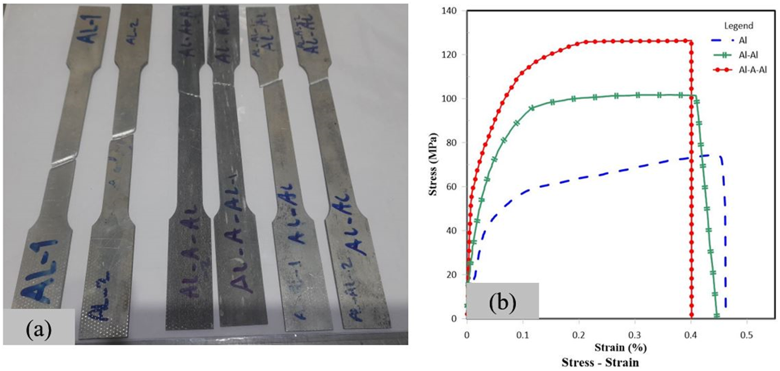
The strength of aluminum 1060 is improved through cold roll bonding and the incorporation of nanoparticles. Tensile test results in Figure 1,
39
indicate that both the yield strength and tensile strength of the composite are enhanced.
39
Tensile test; (a) Dog-bone specimens, (b) Stress-strain curves
39
.
Particle reinforced aluminum matrix composites are extensively utilized in aerospace, military, and automotive industries owing to their favorable properties, including high strength to density ratio, enhanced elastic modulus, superior wear resistance, high thermal conductivity, and excellent corrosion resistance. Among reinforcements,
According to the previous studies: Rezayat et a.
40
fabricated aluminum matrix composites reinforced with submicron
The carbon and E-glass fibers, with a density of 200 g/m2, are supplied by Technopol Company. Additionally, Araldite-Aradur 5052 epoxy resin and 2mm-thick aluminum 1060-T0 are purchased from Huntsman and Alumpars Companies, respectively. The specimens are manufactured using hand lay-up and vacuum bagging methods to remove excess resin and reduce voids. They are cut parallel to the rolling direction, measuring 120*120*2 mm. To ensure adequate bonding, metal surfaces are cleaned with acetone and scratch-brushed using a stainless steel wire brush. The CRB process is carried out on a rolling machine equipped with a 350 mm-diameter, 400 mm-long roller, powered by a 100-hp electric motor, see Figure 2. The mechanical properties are detailed in previous research.
39
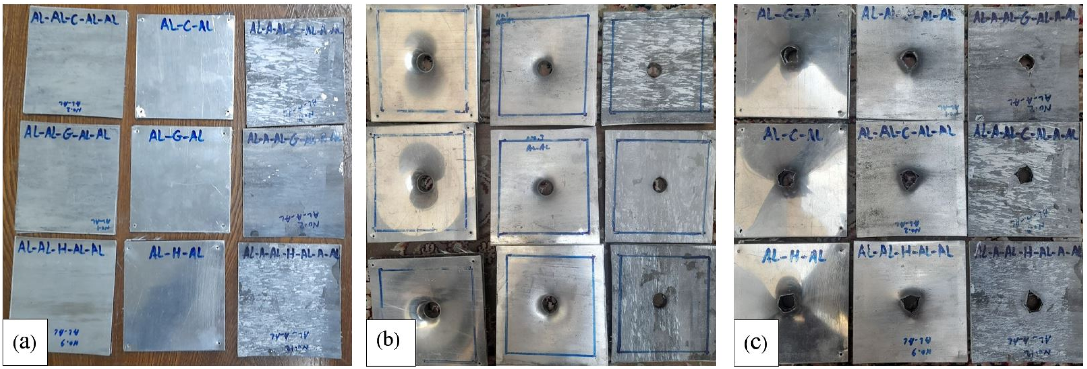
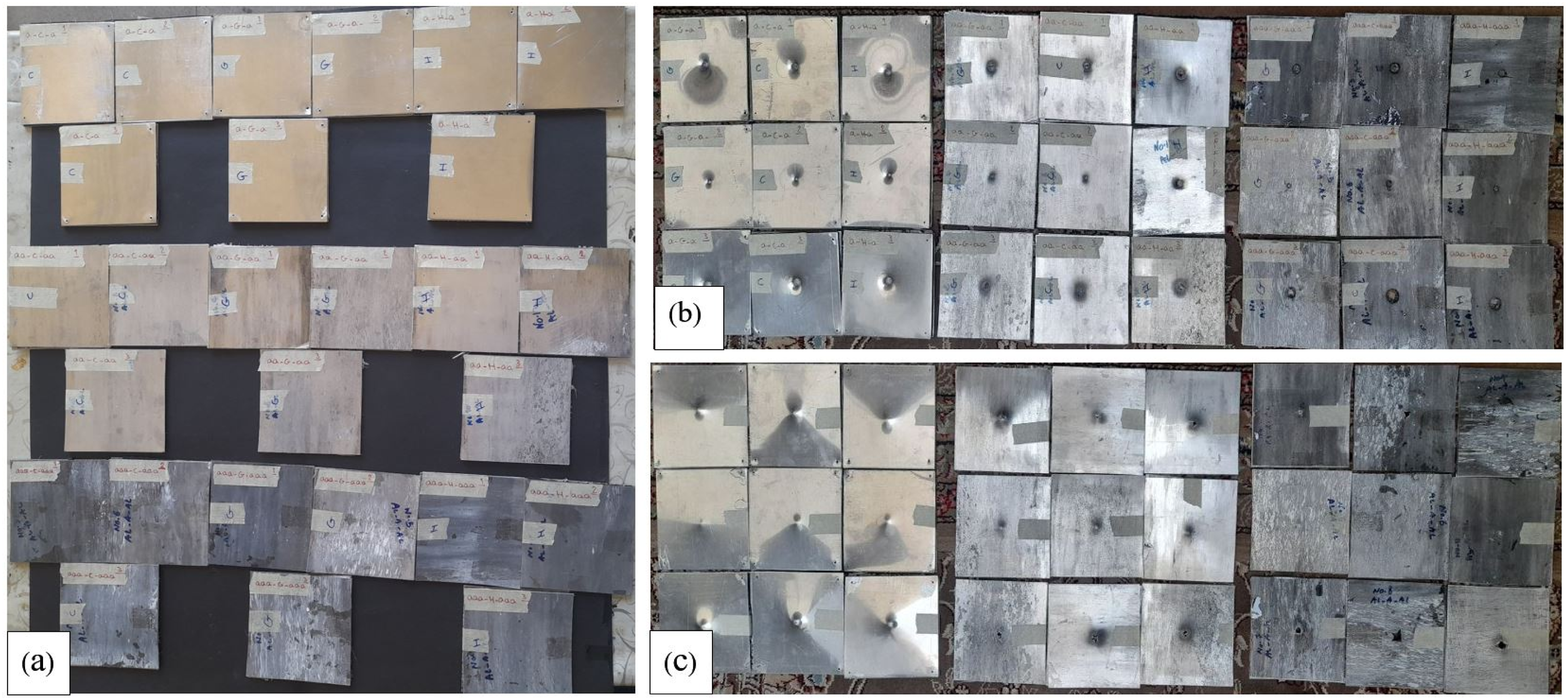
This study divides the specimens into three groups, each with three types. Each type consists of four layers of fiber FMLs preparation procedure: (a) Rolling machine, (b) Rolled aluminum plate, (c) Vacuum bagging composite, (d) Manometer, (e) Vacuum bagging FMLs, (f) Prepared FMLs. FMLs configuration prepared in three groups and three types. Prepared specimen for quasi-static indentation test: (a) Before impact, (b) Front side after impact, (c) Rear side after impact. Prepared specimen for low-velocity impact test: (a) Before impact, (b) Front side after impact, (c) Rear side after impact.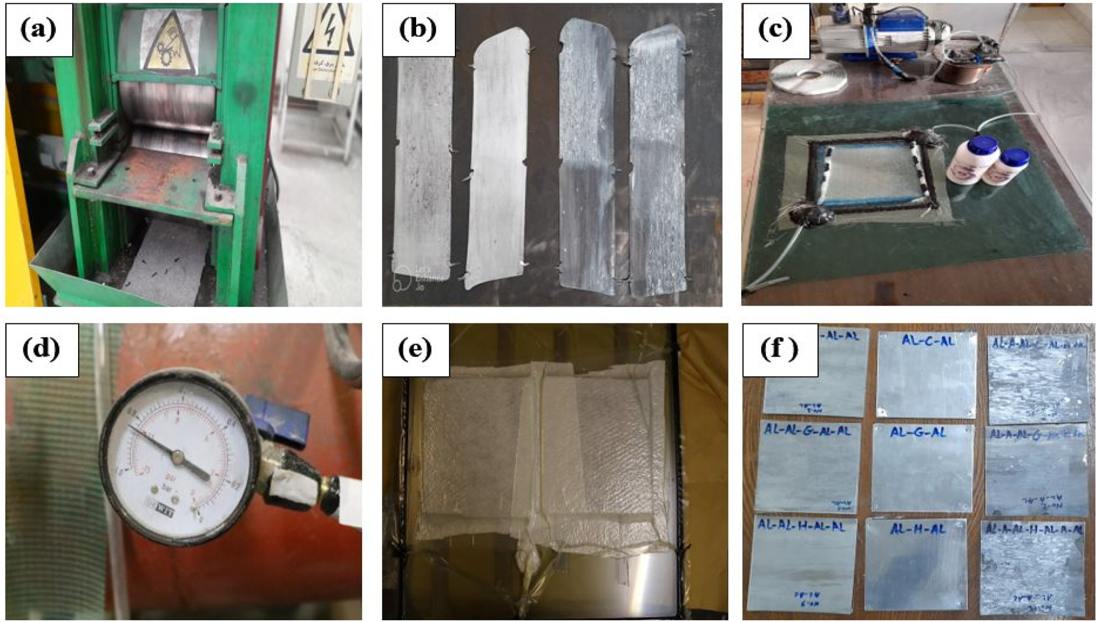

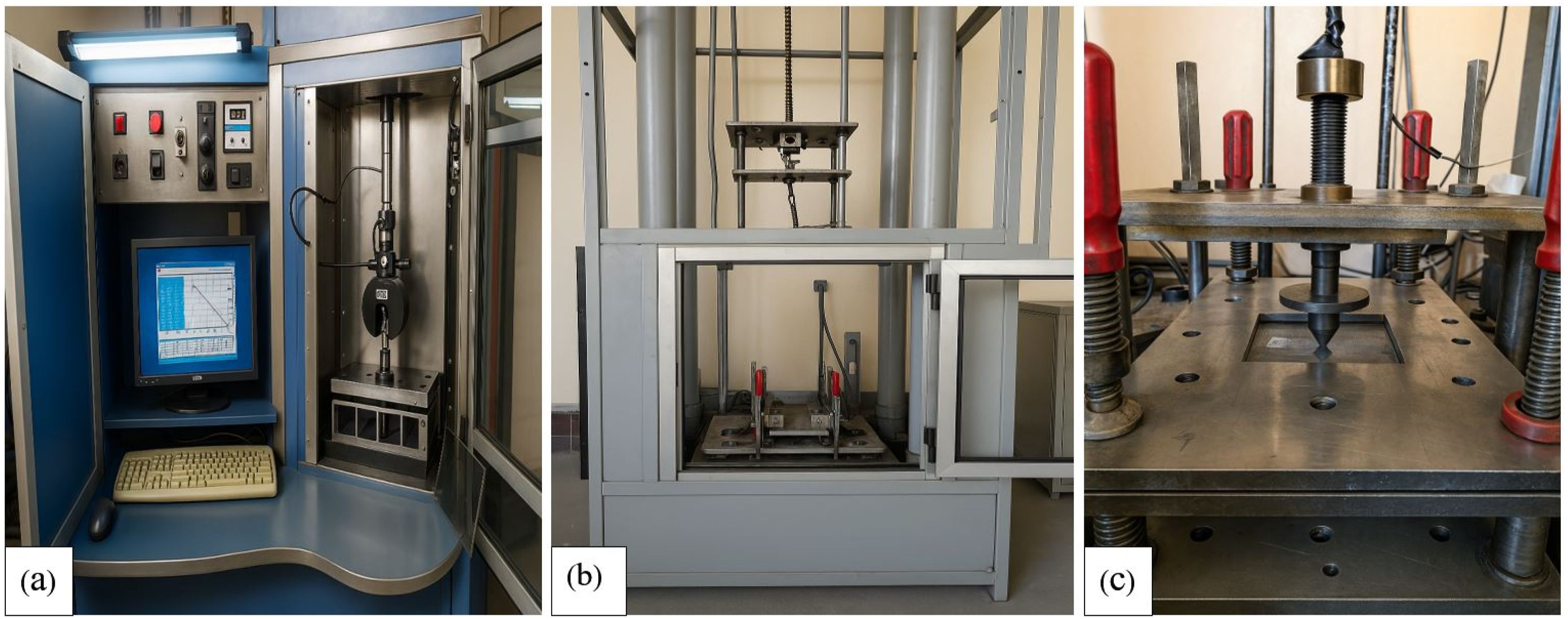
The quasi-static penetration tests were carried out using an INSTRON universal testing machine, integrated with a 150 kN capacity load cell to ensure precise force measurement and control. The displacement rate of the steel conical crosshead with a 16 mm diameter for the quasi-static penetration tests was set at 5 mm/min, referred to in ASTM D6264. The contact load-displacement and strain data were continuously recorded by a specialized computer connected to the testing apparatus.
The low-velocity impact tests were conducted at ambient temperature utilizing an Instron Dynatup drop-weight impact testing system, under the ASTM D7136 standard. The impacts were delivered using a conical steel indenter with a diameter of 16 mm. The striking mass, including the crosshead and indenter, were 2.82 Kg, 5.40 Kg, and 8.00 Kg, see Figure 5. The velocity and displacement of the impactor were obtained by integrating the time-dependent contact force data,
46
as described below by equations (1) and (2)
46
: Test instruments: (a) Universal testing machine, (b) Drop-weight machine, (c) Conical indenter.


The metal volume fraction (MVF) refers to the proportion of metal within the total volume of a composite material, serving as a quantitative measure of the metal content in the composite’s overall composition.47,48 In general, MVF is defined by equation (4), where the 

Glossary of the various FML layup configuration reinforced with NPs and CRBed process.

Numerical simulation, geometry, and damage models
ABAQUS/Explicit finite element software offers interfaces that allow users to implement custom constitutive models. User-defined subroutines become essential when material behavior, particularly nonlinear responses in the plastic region, cannot be directly defined within the CAE environment. These subroutines are also instrumental in modeling complex loading conditions that vary with both time and spatial position, which are difficult to describe using standard CAE functionalities.
This study investigates GLARE, CARALL, and hybrid fiber-metal laminates. The laminate configurations include two aluminum layers with thicknesses of 2 mm for the unrolled specimen and 1 mm for the rolled specimen, fiber plies oriented at 0/90 directions with a thickness of 0.3 mm, and five interlaminar resin layers, each 0.1 mm thick. A rigid projectile with a 16 mm diameter is also included in the model. The mesh size for the specimen components ranges from 0.1 mm to 0.3 mm. The finite element model comprises 1695 elements per specimen component and 934 elements for the projectile. The components of the specimen are explicitly modeled and discretized using appropriate finite element types: the projectile is represented by 4-node three-dimensional bilinear rigid quadrilateral elements (R3D4). Meanwhile, the face sheets and fiber-reinforced polymer (FRP) layers are meshed with 8-node linear brick elements with reduced integration (C3D8R). The interlaminar resin layers are modeled using 8-node three-dimensional cohesive elements (COH3D8), as illustrated in Figure 6. The contact properties of the adhesive can be seen in previous research.
39
The general contact interactions are defined using the ABAQUS/Explicit contact algorithm, incorporating a penalty-based friction formulation and hard contact for normal behavior. FML simulation: (a) stacking sequence, (b) assembled specimen, (c) meshed parts.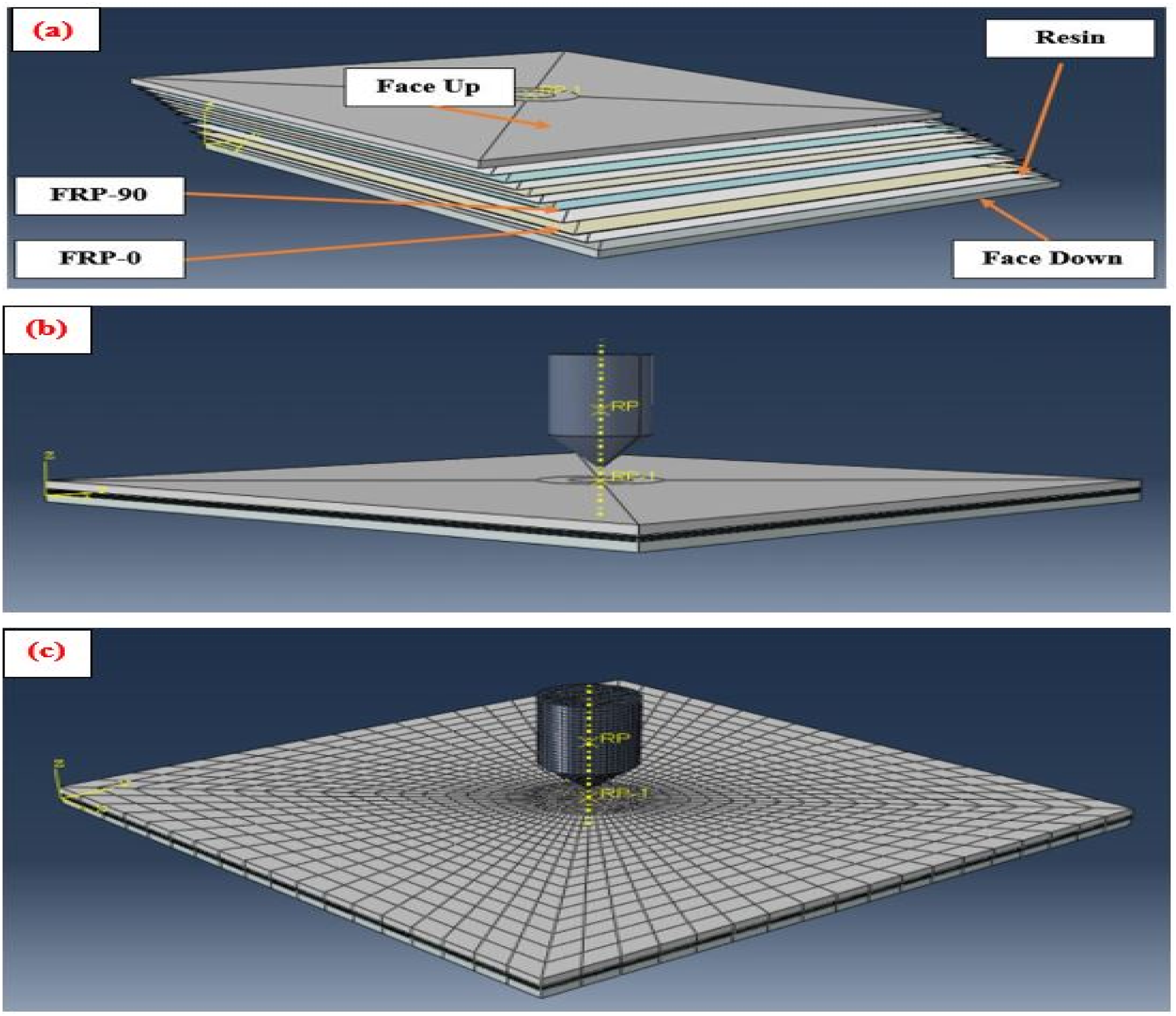
The simulation employs the Johnson-Cook constitutive model, which captures strain-rate sensitivity, strain-hardening behavior, and thermal softening effects. This framework defines equivalent stress as a function of plastic strain, strain rate, and temperature, as expressed in equation (6).
4
In this formulation, 
The term 
The finite element simulation employs the Johnson-Cook (JC) progressive damage model, which facilitates the definition of damage initiation criteria and subsequent damage evolution. This model is well suited for capturing material behavior under high-strain-rate loading conditions.50,51 Material failure is assumed to occur when the accumulated damage parameter reaches a critical threshold value of 1.0, as described by equation (8)50,51:
In the Johnson-Cook damage model, the equivalent plastic strain at the initiation of damage, 
Damage resulting from material failure under stress can be classified as brittle or ductile. In ductile damage, the material deforms plastically before fracturing. Once the fracture energy exceeds a critical threshold, the software evaluates each material point against the failure criterion at every increment, continuing until element deletion or completion of the impact event. The Hashin failure criteria characterize the damage behavior of fiber-reinforced composites under various stress conditions. By distinguishing between fiber and matrix failure modes through separate equations, the model offers greater accuracy than conventional tensile or shear criteria. Its ability to account for multiple simultaneous stress states makes it particularly suitable for composite materials. Accordingly, the Hashin criterion is used to simulate damage in CFRP and GFRP specimens.52,53 The failure modes of fiber tension, fiber compression, matrix tension, and matrix compression are defined by Equations (10) to (13)52,53:


The Hashin failure criterion is formulated to capture anisotropic damage mechanisms in elastic-brittle materials. It is suitable for modeling fiber-reinforced polymer (FRP) composites that exhibit direction-dependent mechanical responses. Within this framework, the progressive degradation of material stiffness due to damage is represented by a damaged stiffness matrix, 
In fiber-metal laminate (FML) specimens, various failure mechanisms, including metal layer rupture, fiber breakage, matrix cracking, and interfacial debonding or delamination, are typically observed in the impact-affected zone. These damage phenomena contribute significantly to the laminate’s energy absorption capacity, primarily through the accumulation of permanent plastic strain energy. The onset of damage is commonly initiated at the metal-fiber/matrix interface, characterized by matrix bending and shear-induced cracking resulting from localized stress concentrations. Cohesive zone modeling is employed to accurately capture interfacial delamination between the metallic face sheets and composite layers. This approach utilizes cohesive elements in conjunction with a traction-separation law, governed by the Benzeggagh-Kenane (B-K) mixed-mode fracture criterion, as described in equations (15) and (16).
54
The B-K model enables the characterization of delamination propagation under combined mode I (opening) and mode II (sliding) loading conditions, providing a more realistic representation of interfacial failure behavior in hybrid laminates.
54


Results and discussion
Experimental results
Quasi-static indentation test results
Quasi-static indentation tests are conducted on three FML groups, with fracture mechanisms, load-displacement responses, specific energy absorption, and absorbed energy presented in Figures 7 to 11 and Table 3. G-1 perforated specimens. G-2 perforated specimens. G-3 perforated specimens. Load-displacement curves: (a) G-1 specimens, (b) G-2 specimens, (c) G-3 specimens. Calculation of specific energy absorption for three groups of specimens.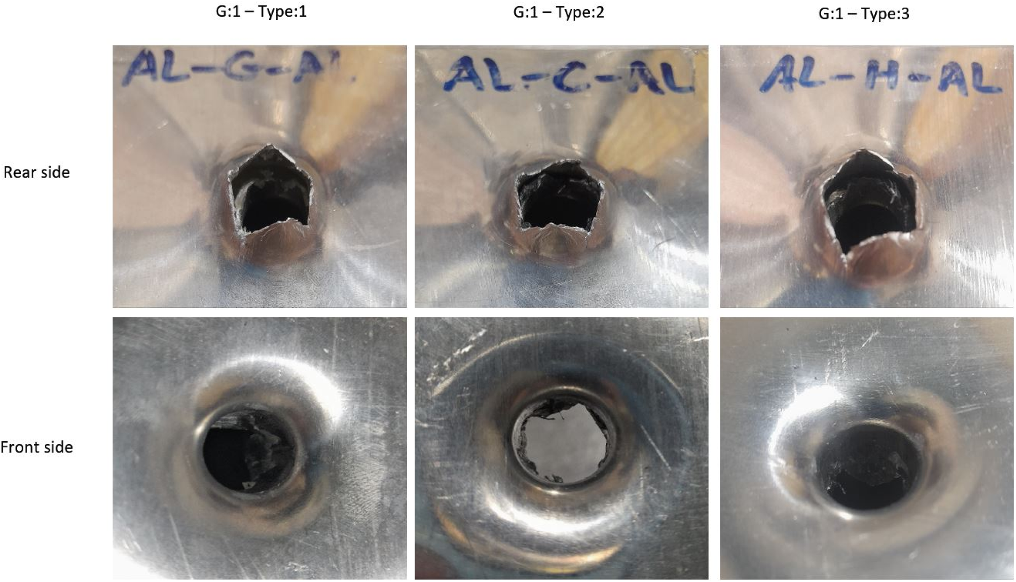
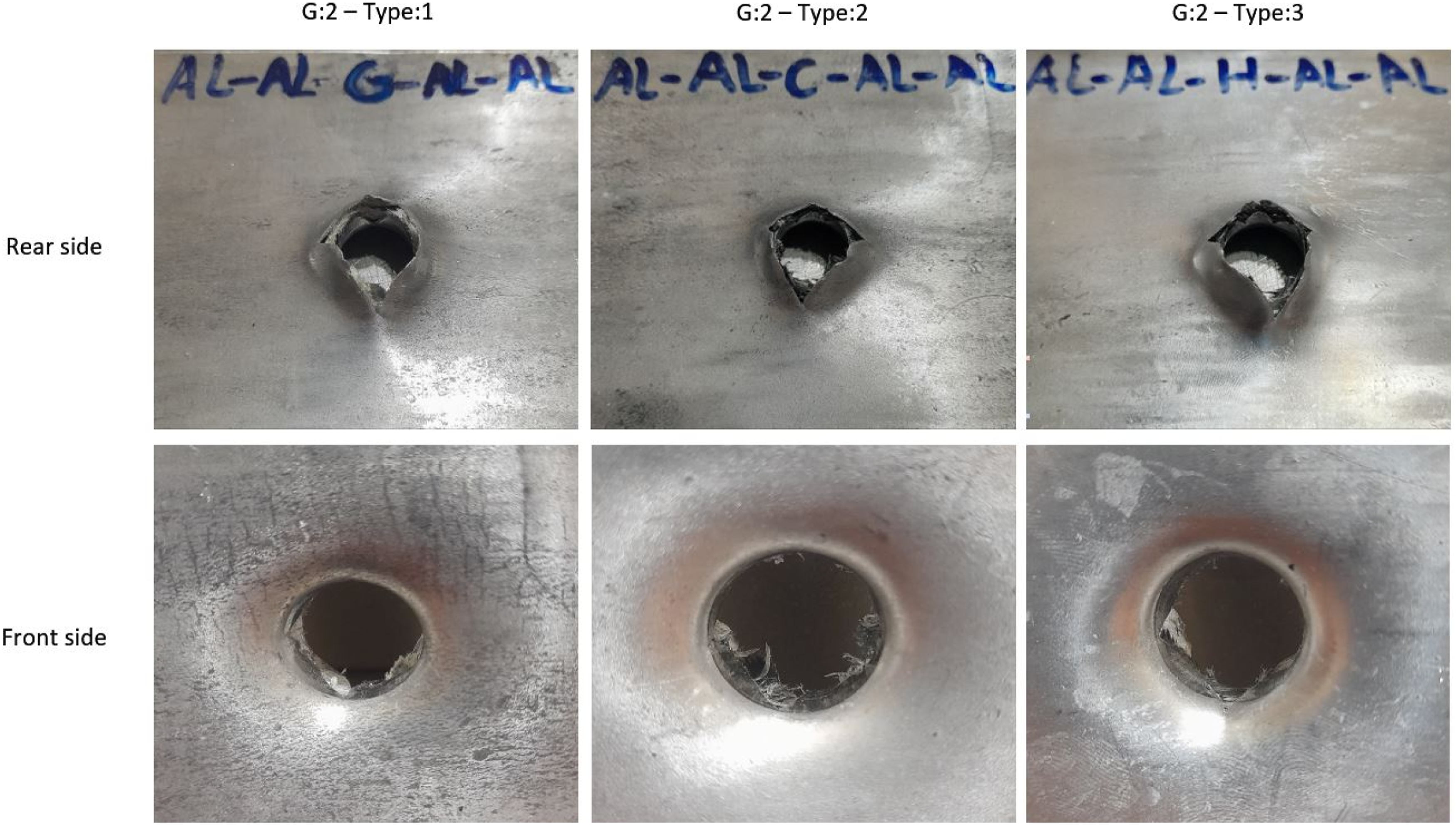
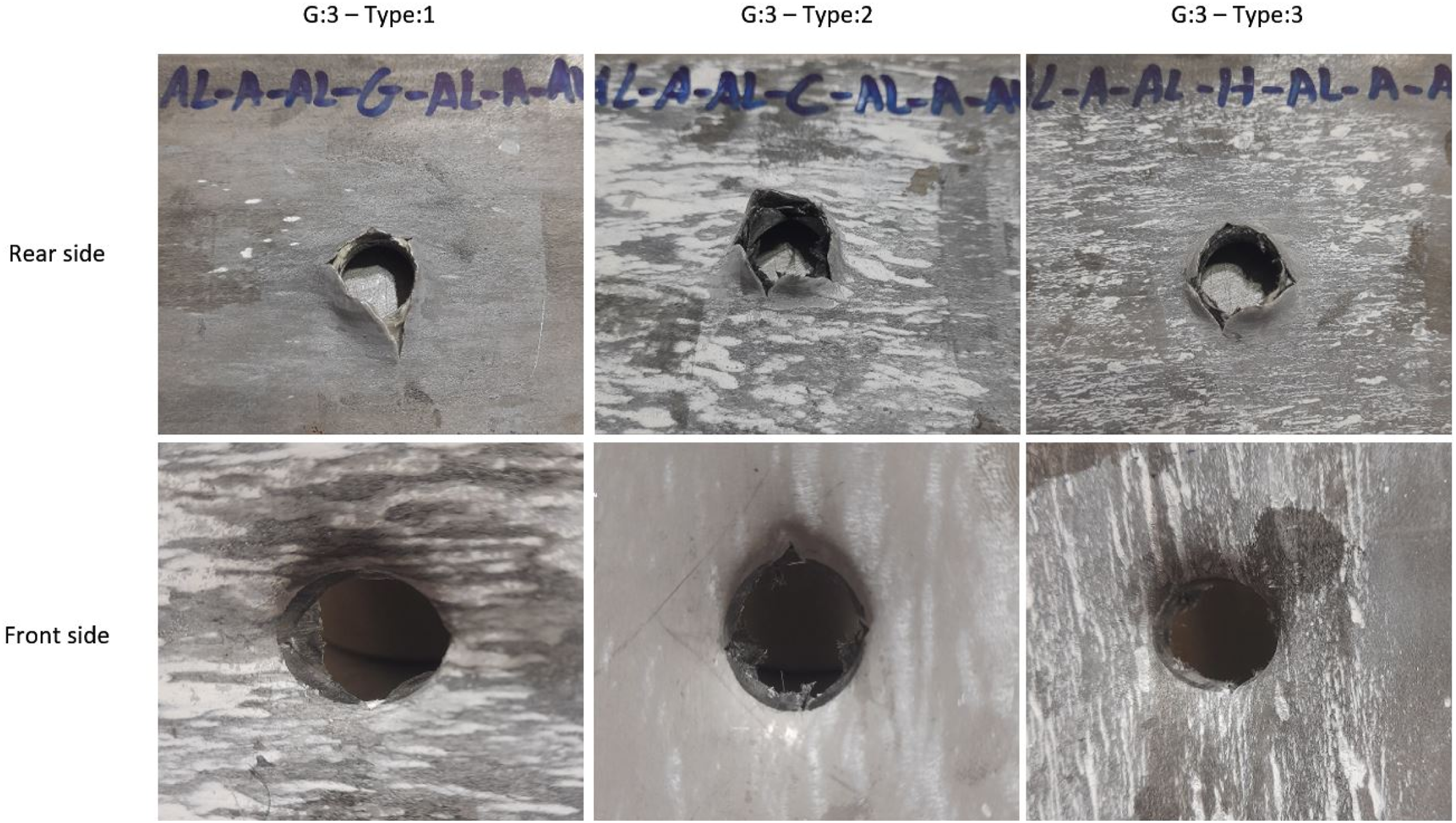
The G-1 specimens represented in Figure 7 exhibited frontal bulging, which is out-of-plane deformation on the impacted side of the FML caused by localized compressive stresses. The aluminum layer experienced plastic deformation, resulting in outward bulging. Rear-side petalling, which consists of radial tear cracks, is also observed on the rear side of the FML. Dishing with non-propagating cracks involves restricting the cracks around the damaged area before further propagation. Fiber breakage has a significant impact on energy dissipation, ultimately preventing crack growth. In contrast, the G-2 and G-3 specimens illustrate in Figures 8 and 9 show frontal bulging and petalling, as well as rear-side petalling and progressive crack growth reaching the FML surface. This phenomenon results in more energy absorption.
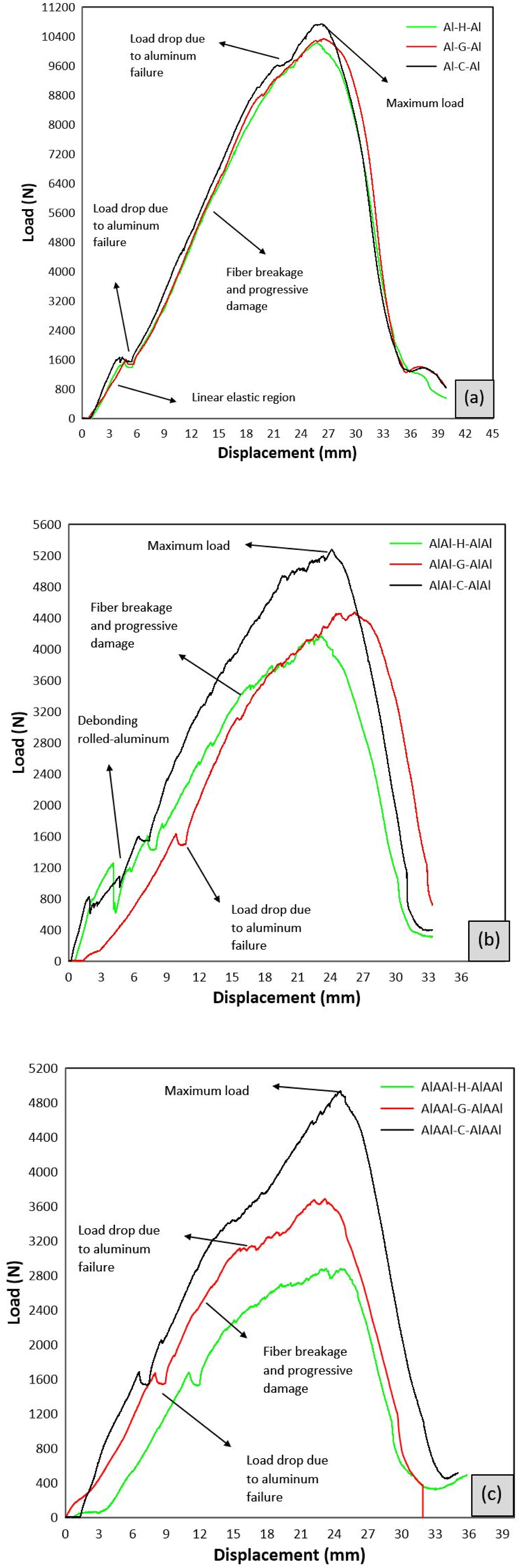
Figure 10 shows the load-displacement curves for G-1, G-2, and G-3 FMLs, each with three design modifications. The results indicate that carbon FMLs absorbed more energy than glass-based and hybrid-based FMLs. For G-1 specimens, the response is initially linear until a sudden load drop occurred at about 1.6 KN between 3 and 4 mm displacement. Then, progressive fiber damage developed, with the load reaching peaks of 8.8 kN and 9.6 kN. A subsequent drop is due to impact with the lower aluminum plate, followed by a final increase in load to nearly 10 kN before the final failure. The load-displacement curves of G-2 and G-3 specimens show fluctuations during loading, caused by localized surface hardness and partial debonding of the rolled aluminum plates, leading up to the upper plate failure. The response for G-2 fluctuated, while G-3’s response is initially linear until a sudden load drop at 1.6 kN, with displacement reaching up to 10 mm. Then, progressive fiber damage occurs as the load increases to reach peak loads, ranging from 2.8 kN to 5.4 kN. The maximum load in G-2 and G-3 specimens was lower than in G-1, due to reduced plate thickness and lower mass.
More explanation details consist of: Figure 10(a) illustrates the indentation behavior of three laminate configurations, namely Al-H-Al, Al-G-Al, and Al-C-Al, subjected to a quasi-static indentation using a conical indenter with a diameter of 16 mm and a loading rate of 5 mm/min. The overall shape of the load-displacement curves can be divided into several characteristic regions corresponding to different deformation and failure mechanisms occurring within the laminate structure. Initially, the curves exhibit a linear increase in load with increasing displacement, which corresponds to the elastic bending response of the laminate. In this stage, the applied load is primarily supported by the combined bending stiffness of the aluminum face sheets and the fiber-reinforced composite core. The deformation is predominantly elastic, and no significant damage is expected within the composite layers. The slope of this initial linear region represents the effective structural stiffness of the laminate, which depends on the elastic modulus of the constituent materials and the overall laminate architecture. As the displacement increases to approximately 4-6 mm, a slight deviation from linearity and a small load drop can be observed in the curves. This phenomenon is typically associated with the onset of localized plastic deformation or micro-cracking in the upper aluminum sheet, which is directly in contact with the indenter. At this stage, stress concentration beneath the indenter leads to yielding of the aluminum layer and may also initiate interfacial debonding between the metal and composite layers. Such early damage mechanisms reduce the local stiffness and cause a temporary reduction in the load. Following this stage, the load continues to increase with displacement, indicating that the laminate is still capable of sustaining additional load despite the initiation of local damage. In this region, progressive damage mechanisms develop within the composite core. These mechanisms include matrix cracking, fiber-matrix debonding, interlaminar delamination, and gradual fiber fracture. Meanwhile, the aluminum layers undergo plastic deformation and contribute significantly to the overall load-carrying capacity through membrane stretching. The interaction between plastic deformation in the metallic layers and progressive damage in the composite layers results in a stable load increase. The load reaches its maximum value at a displacement of approximately 25–27 mm. This peak load represents the maximum indentation resistance of the laminate system. At this point, extensive damage has accumulated within the composite plies, and a large portion of the fibers beneath the indenter has fractured. Simultaneously, the lower aluminum sheet experiences severe tensile stresses due to bending and stretching, approaching its ultimate failure limit. A sudden load drop occurs immediately after the peak load, which corresponds to the catastrophic failure of the laminate. This rapid decrease in load is mainly attributed to the tearing or fracture of the bottom aluminum sheet. Once the bottom metallic layer fails, the structural integrity of the laminate is significantly compromised, and the indenter rapidly penetrates through the remaining damaged composite layers. At larger displacements (approximately 35–40 mm), the load approaches a relatively low value, indicating that the indenter has nearly perforated the laminate and the remaining resistance is mainly due to friction and residual material deformation. A comparison of the three laminate configurations reveals noticeable differences in their load-bearing capacity. The Al-C-Al laminate exhibits the highest maximum load, followed by Al-G-Al and Al-H-Al. This behavior can be attributed to the superior mechanical properties of carbon fibers, which possess a higher elastic modulus and tensile strength compared to glass fibers. Consequently, laminates reinforced with carbon fibers provide greater resistance to indentation and higher structural stiffness. In contrast, laminates reinforced with glass fibers generally exhibit larger deformation but lower peak load due to the relatively lower stiffness of glass fibers. The hybrid laminate (Al-H-Al), which contains both carbon and glass fibers, demonstrates intermediate behavior. Although hybridization can improve damage tolerance and energy absorption in some cases, the mismatch in stiffness between the different fiber types may promote interlaminar stresses and delamination, which can slightly reduce the maximum load capacity. Another important parameter that can be derived from the load-displacement curves is the absorbed energy during indentation. The absorbed energy corresponds to the area under the load-displacement curve and represents the laminate’s ability to dissipate mechanical energy through plastic deformation and damage mechanisms. Higher absorbed energy generally indicates better impact resistance and improved damage tolerance.
Figure 10(b) shows the initial linear segment up to approximately 3-4 mm displacement indicates elastic bending behavior. The parts of the structure, including the aluminum face sheets and the fiber-reinforced core, exhibit primarily elastic deformation, supported by the effective stiffness of the combined materials. The first notable feature, a sudden drop in load near 6-9 mm displacement, corresponds to the onset of aluminum sheet debonding or micro-cracking, triggered by localized yielding and shear stresses. This phenomenon signifies the beginning of damage accumulation particularly at the interfaces and within the aluminum layers, which are significantly thinned to only 1 mm due to cold rolling. The reduction in aluminum thickness diminishes its load-bearing contribution, making the laminate more susceptible to failure at quasi-static loads. Further into the displacement range around 9-18 mm, another load drop is observed, which is attributed to fiber rupture and progressive delamination within the composite core. This key damage event, marked as fiber breakage and progressive damage, indicates the development of micro-damage mechanisms such as matrix cracking, fiber-matrix debonding, and interlaminar delaminations. Despite the damage, the structure maintains a certain load-carrying capacity, reflective of damage tolerance and energy absorption through gradual failure. At the peak load, approximately 5200 N, the laminate reaches its maximum resistance before catastrophic failure. This ultimate point signifies extensive damage including fiber fractures, interfacial debonding, and the ultimate tearing of the aluminum sheets. Post-peak, a sharp load reduction indicates complete structural failure due to the tearing or failure of the bottom aluminum sheet, causing the indenter to penetrate fully through the compromised laminate. The comparative analysis of the three configurations reveals that the specimen with carbon fibers (AlAl-C-AlAl) exhibits superior indentation resistance, attributable to the higher tensile strength and elastic modulus of carbon fibers. Conversely, the glass fiber-reinforced laminate (AlAl-G-AlAl) shows lower peak loads, emphasizing the influence of fiber stiffness and failure modes.
The load-displacement curves presented in Figure 10(c) illustrate the quasi-static indentation (QSI) response of nano-modified fiber metal laminates incorporating alumina
For the unrolled FMLs, the aluminum layers retain their original thickness and the bonding between layers is primarily governed by adhesive or interfacial adhesion mechanisms. The load-displacement response initially exhibits a linear elastic region associated with global bending deformation of the multilayer structure. As indentation progresses, early load fluctuations appear due to the initiation of localized damage mechanisms such as matrix cracking, interfacial debonding, and localized yielding of the aluminum layers. Owing to the relatively weaker interfacial bonding in these laminates, interlaminar delamination emerges as one of the dominant damage mechanisms. At higher displacement levels, damage propagates progressively within the composite core through fiber fracture, matrix cracking, and extensive delamination. The final stage of the response is characterized by tearing of the bottom aluminum layer, leading to complete penetration of the indenter and a sharp drop in the load. Overall, the failure process in the unrolled laminates is dominated by early interfacial separation and progressive composite damage.
In the rolled laminates, the rolling process reduces the thickness of the aluminum layers and significantly enhances the mechanical bonding between adjacent layers. This structural modification alters the deformation behavior and damage progression under indentation loading. The initial slope of the load-displacement curve is typically higher than that of the unrolled laminates, reflecting the increased structural compactness and improved load transfer efficiency resulting from the rolling process. With increasing displacement, localized plastic yielding of the thinner aluminum layers occurs before significant interfacial separation. This phenomenon manifests as minor load drops in the curves. During the intermediate stage, the laminate undergoes a combination of plastic deformation in the aluminum layers and progressive damage in the composite core, including matrix cracking, gradual fiber breakage, limited delamination, and strain hardening of the aluminum. Due to the improved bonding between layers, stress redistribution becomes more uniform and the damage evolves in a more stable and progressive manner compared to the unrolled laminates. The final failure occurs when tensile stresses exceed the strength of the bottom aluminum layer, resulting in tearing and complete perforation.
The third group consists of rolled laminates reinforced with alumina nanoparticles poured between the aluminum layers prior to rolling. This nano-modification further alters the mechanical response and damage mechanisms of the laminates. The initial elastic stiffness is the highest among the three groups, which can be attributed to the enhanced local stiffness of the aluminum layers and the improved interfacial shear strength induced by the presence of

Calculation of absorbed energy for three groups of specimens.

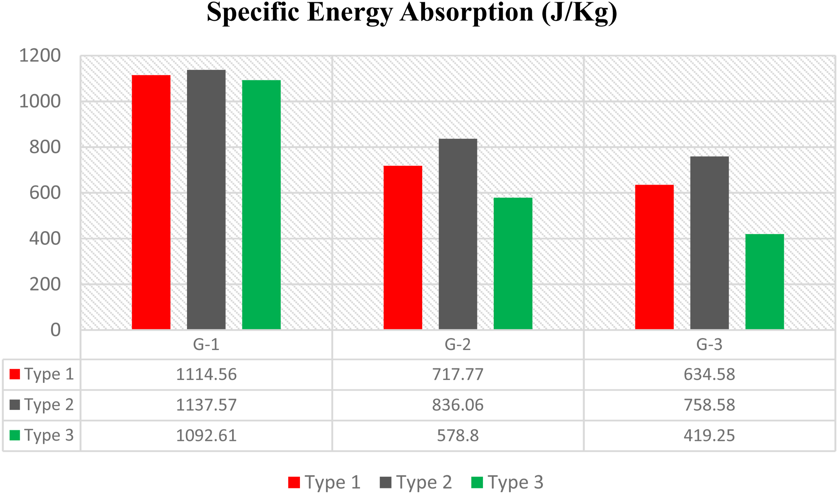
Table 4 presents the absorbed energy and specific energy absorption (SEA) for three groups of specimens (G-1, G-2, and G-3). The G-1 group consists of 2-mm-thick pure aluminum on each side of the FML, reinforced with glass, carbon, and hybrid fibers. Furthermore, the G-2 group consists of two 4-mm-thick pure aluminum plates rolled down to 1 mm. These 1 mm aluminum layers are placed on each side of the FML and reinforced with the aforementioned fibers. The G-3 group features two 4-mm-thick pure aluminum plates rolled down to 1 mm, with 400-nm aluminum oxide (
As shown in Figure 11, G-1 specimens overall exhibited higher SEA values, ranging from 1092 J/kg to 1137 J/kg, surpassing both G-2 and G-3. Specifically, G-1/Type-1 absorbed 155.28% and 175.63% higher SEA compared to G-2/Type-1 and G-3/Type-1, respectively. Similarly, G-1/Type-2 showed increases of 136.06% and 149.96% over G-2/Type-2 and G-3/Type-2. For Type-3 configurations, the SEA of G-1 was 188.77% and 260.61% higher than that of G-2 and G-3, respectively.
Low-velocity impact test results
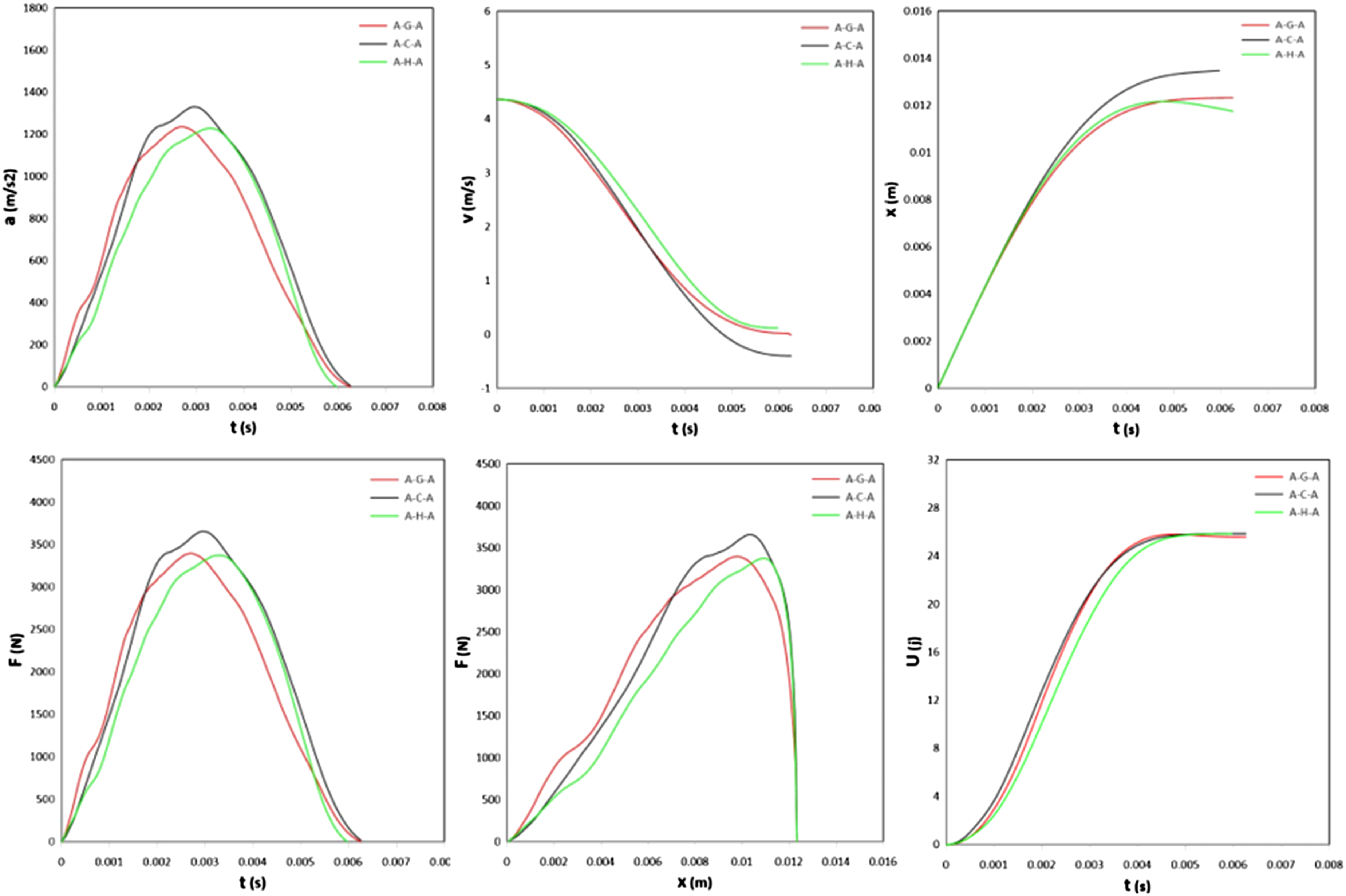
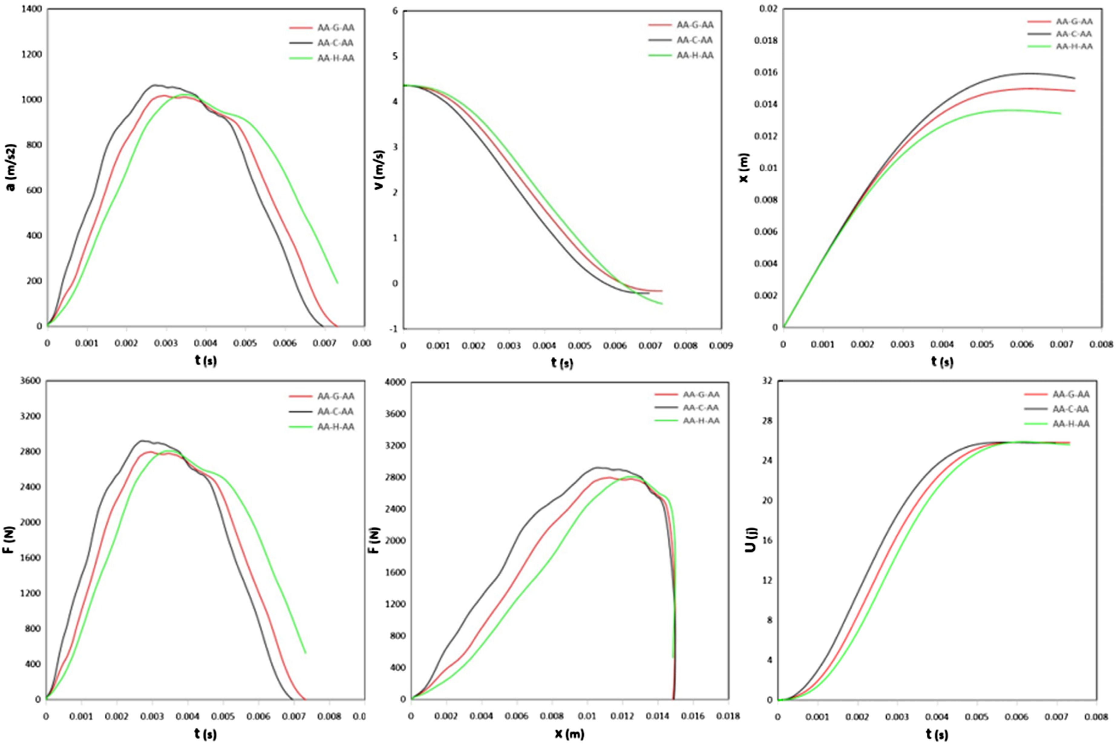
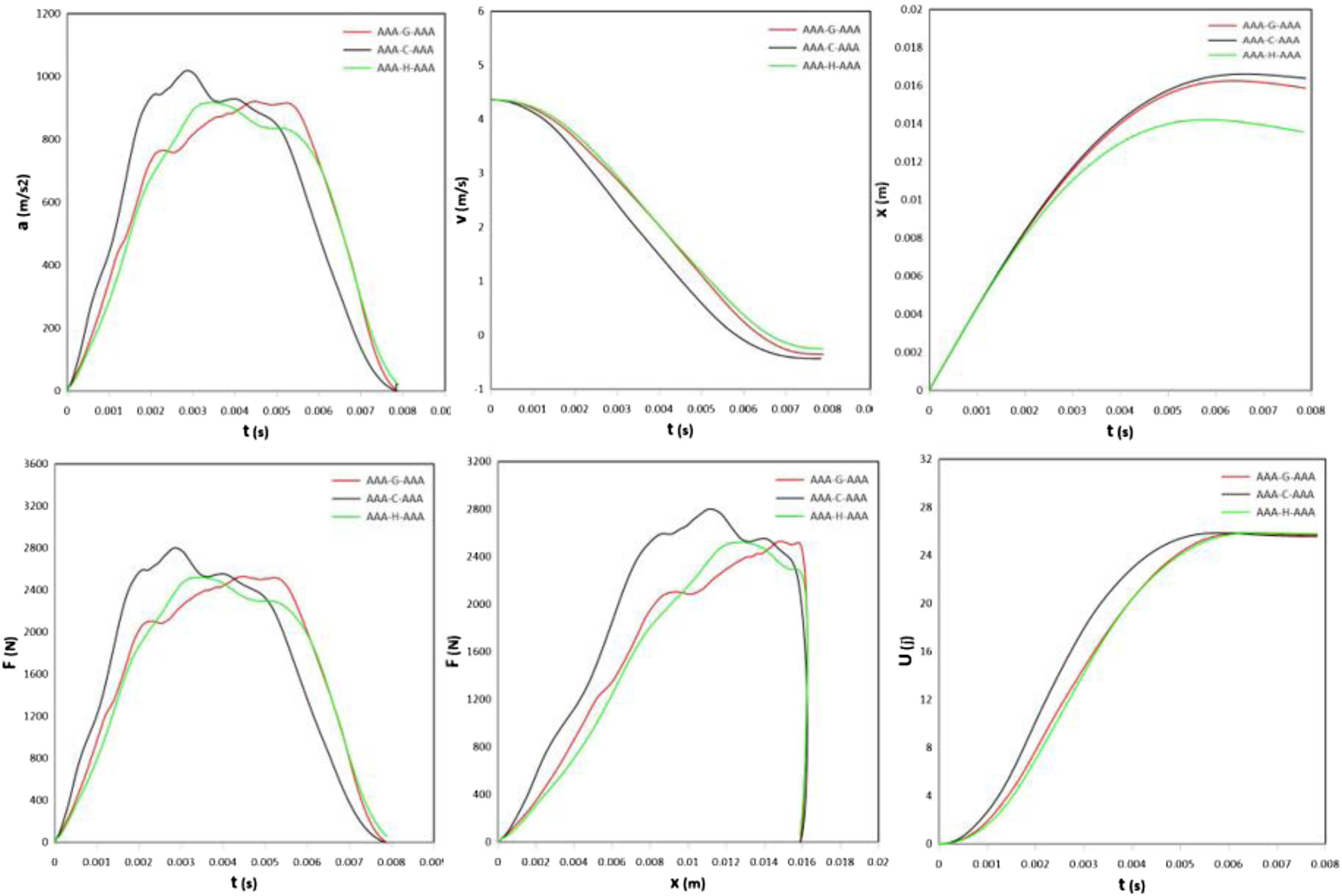
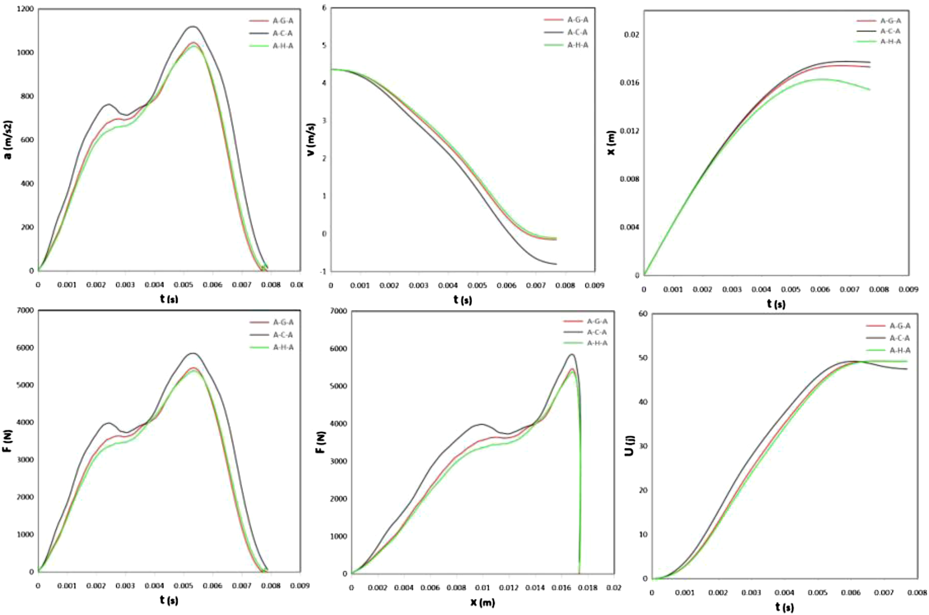
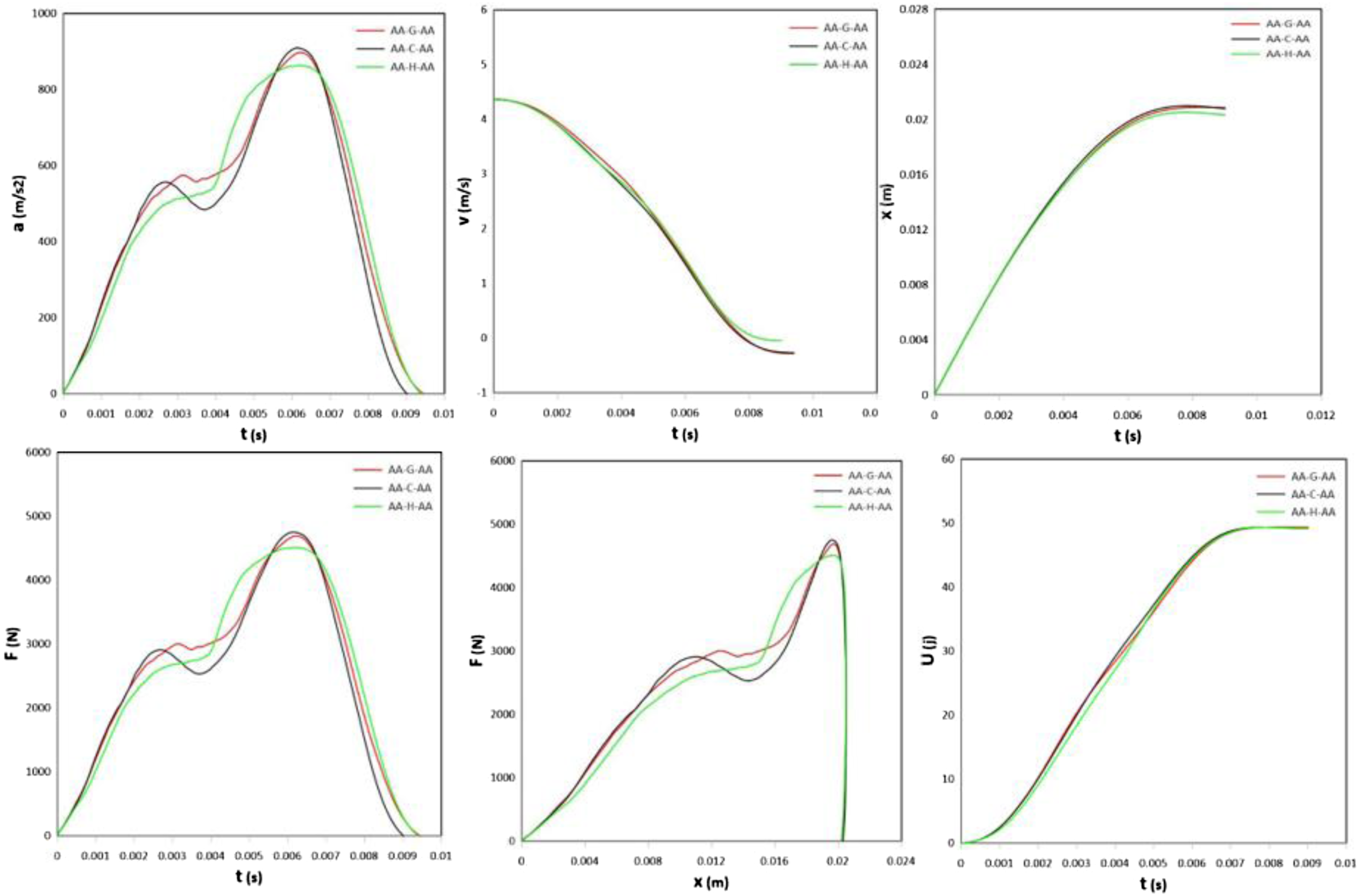
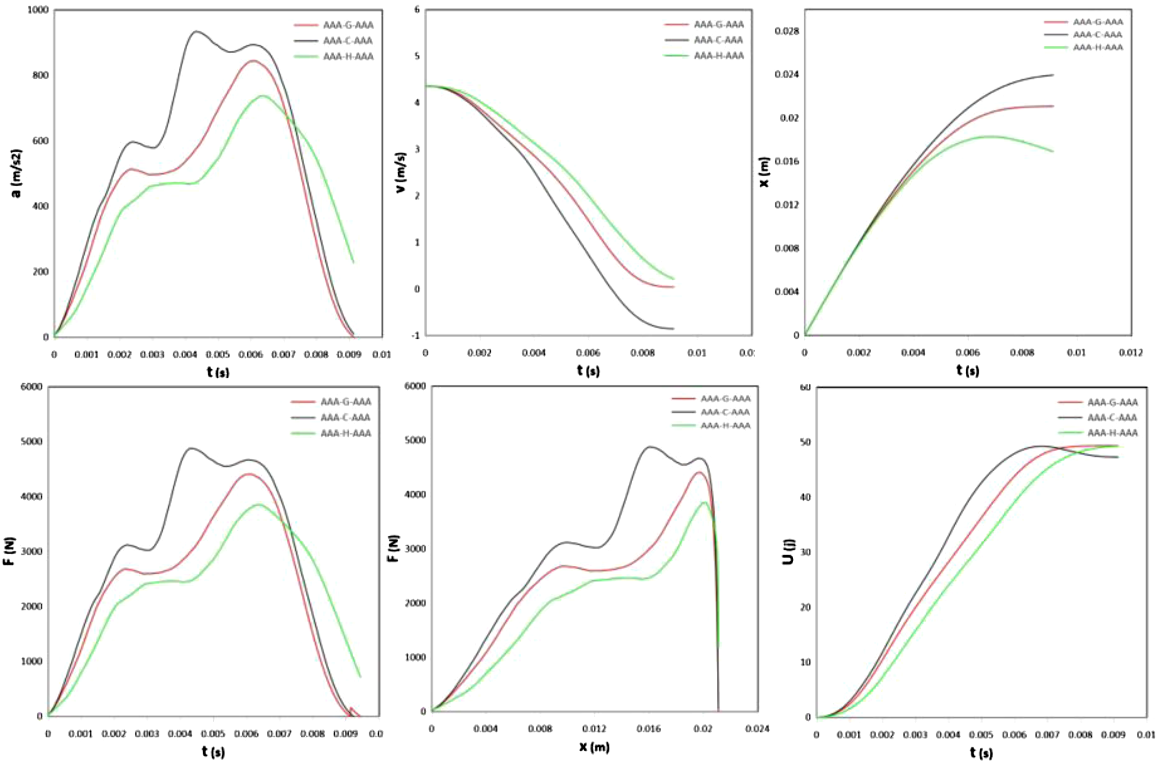
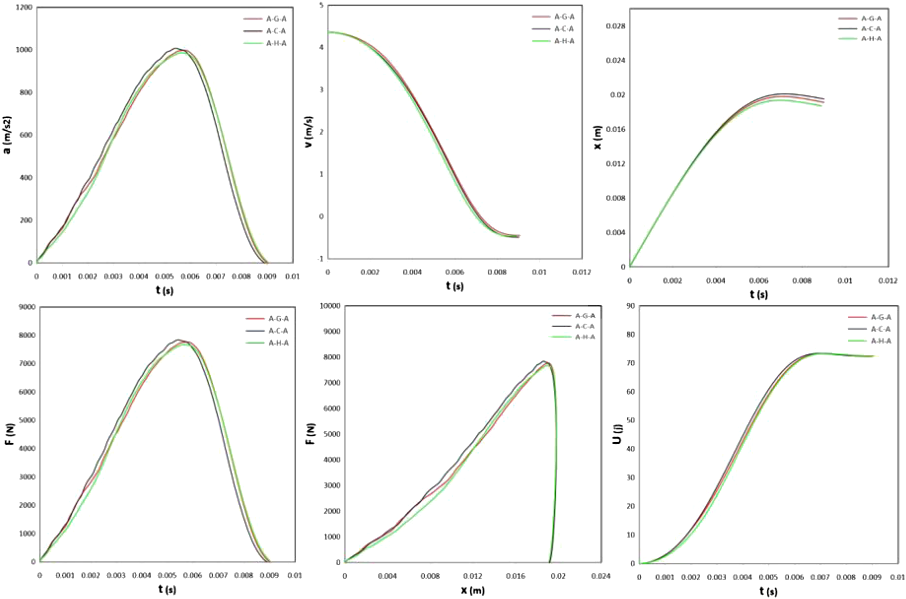
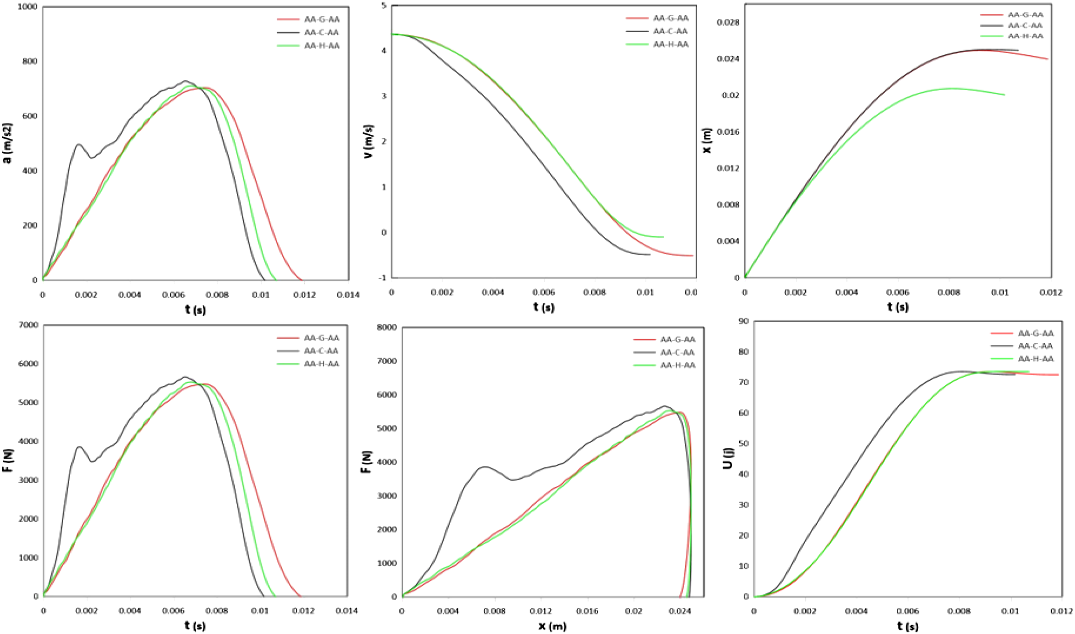
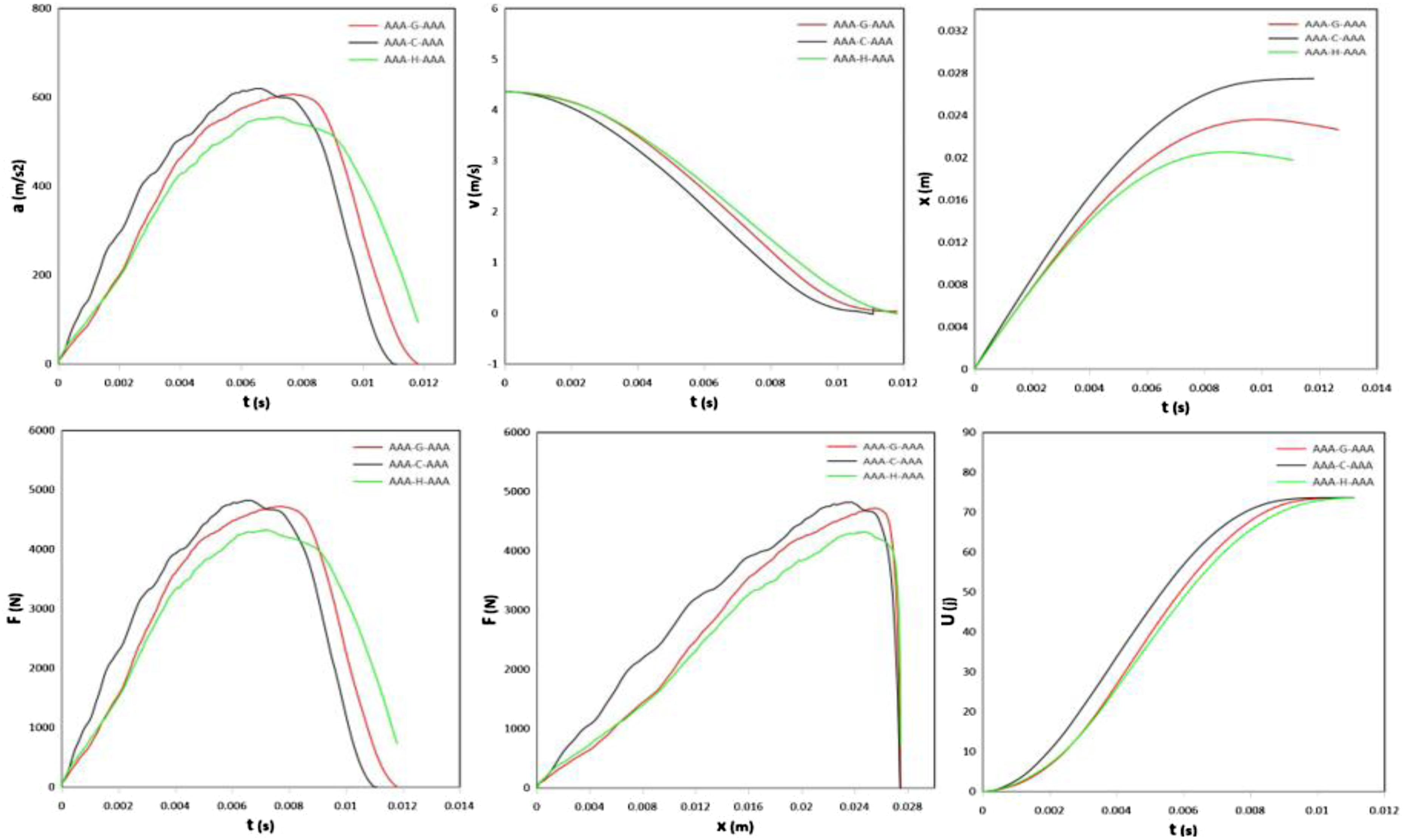
Low-velocity impact tests are performed on three groups of samples: G-1, G-2, and G-3. Each group comprised three types, with each type subjected to impact energies of 26, 50, and 74 joules. For each energy level, three samples are tested. In total, 81 samples are impacted, and the average results are presented in this paper. The fracture mechanisms and failure modes observed on the front and rear faces of the specimens are shown in Figures 12 to 14 and Figures 15 to 17, respectively. Figures 18 to 26 illustrate the acceleration-time, velocity-time, displacement-time, force-time, force-displacement, and energy-time curves. The corresponding results determined from the initial force and initial velocity applied to the samples are summarized in Tables 5 to 7. Front-side of glass fiber-reinforced FMLs, categorized into three groups under three impact energy levels. Front-side of carbon fiber-reinforced FMLs, categorized into three groups under three impact energy levels. Front-side of hybrid fiber-reinforced FMLs, categorized into three groups under three impact energy levels. Rear-side of glass fiber-reinforced FMLs, classified into three groups and impacted at three energy levels. Rear-side of carbon fiber-reinforced FMLs, classified into three groups and impacted at three energy levels. Rear-side of hybrid fiber-reinforced FMLs, classified into three groups and impacted at three energy levels. Plotted response curves of G-1 specimens under 26 J impact energy. Plotted response curves of G-2 specimens under 26 J impact energy. Plotted response curves of G-3 specimens under 26 J impact energy. Plotted response curves of G-1 specimens under 50 J impact energy. Plotted response curves of G-2 specimens under 50 J impact energy. Plotted response curves of G-3 specimens under 50 J impact energy. Plotted response curves of G-1 specimens under 74 J impact energy. Plotted response curves of G-2 specimens under 74 J impact energy. Plotted response curves of G-3 specimens under 74 J impact energy. Energy dissipation results for three groups of specimens under low velocity impact based on U(J) = 26. Energy dissipation results for three groups of specimens under low velocity impact based on U(J) = 50. Energy dissipation results for three groups of specimens under low velocity impact based on U(J) = 74.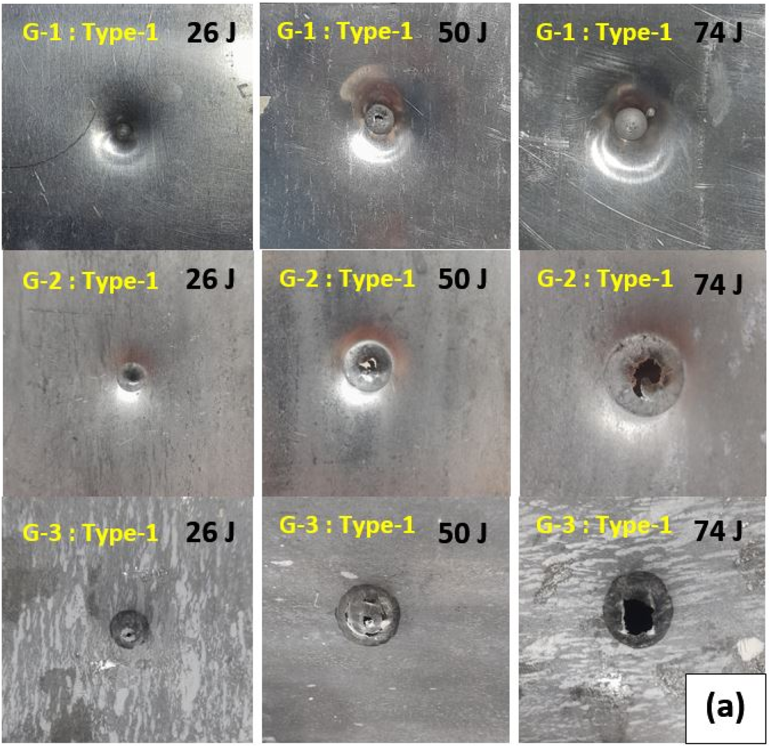
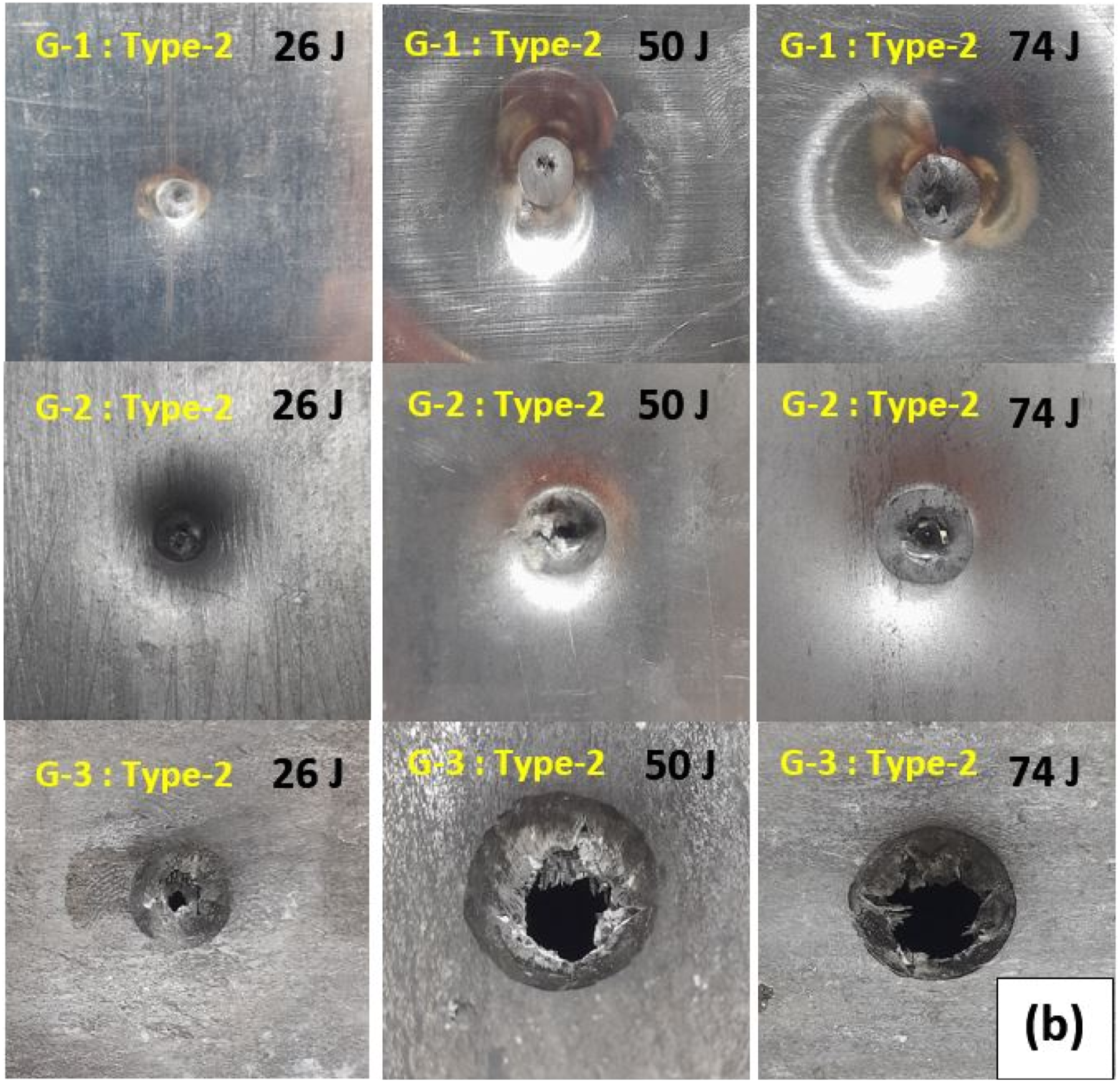
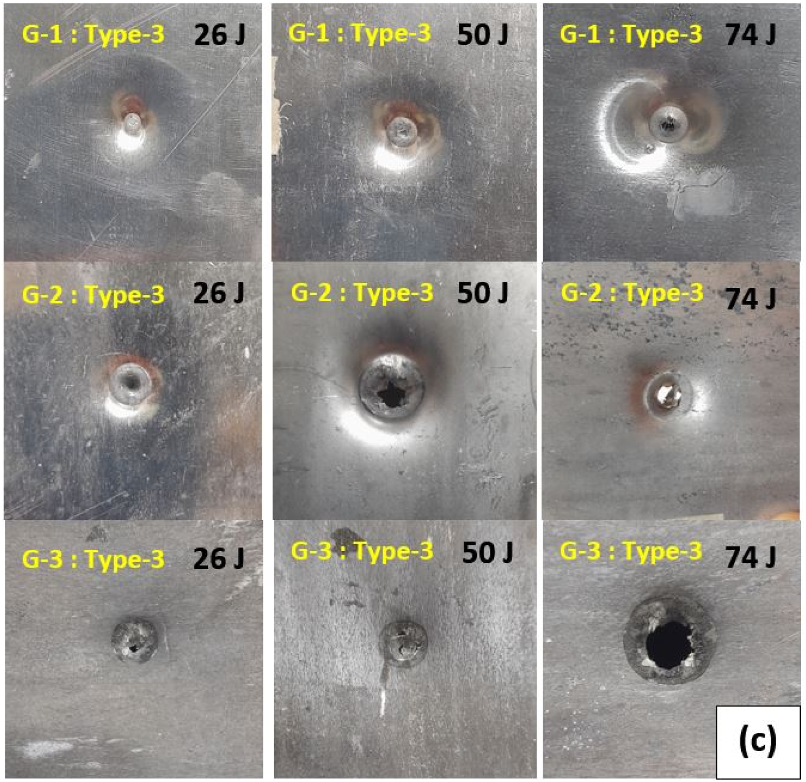
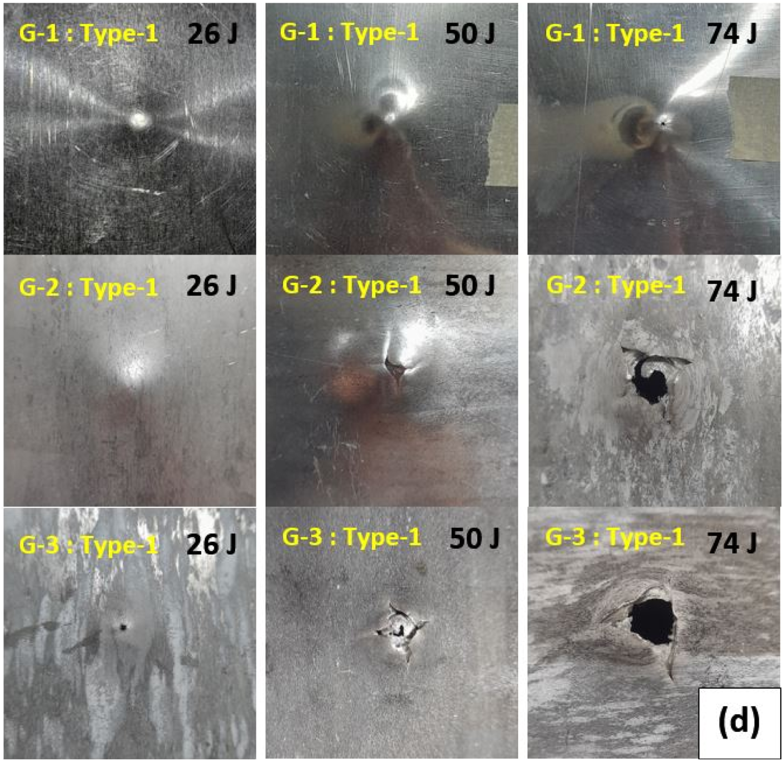
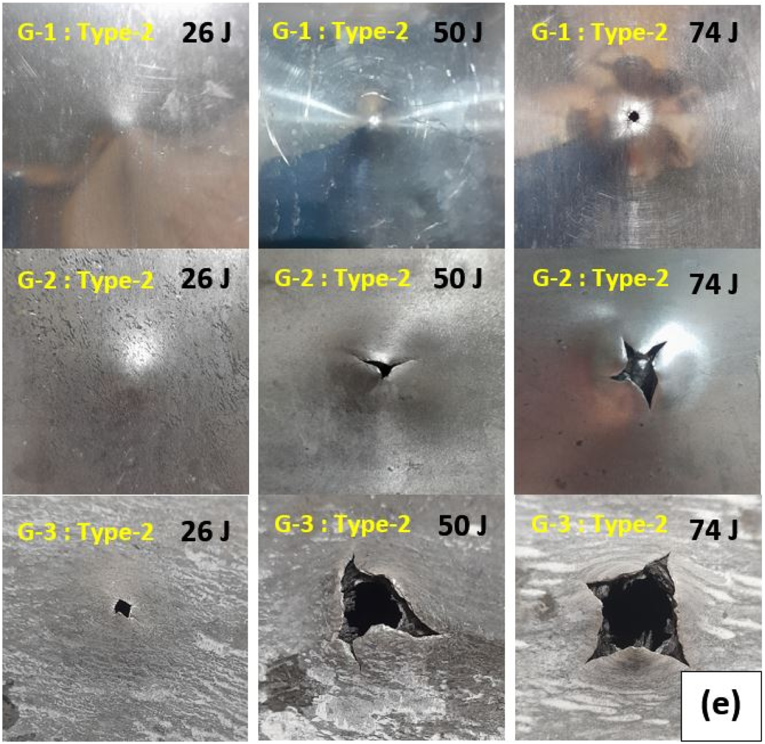
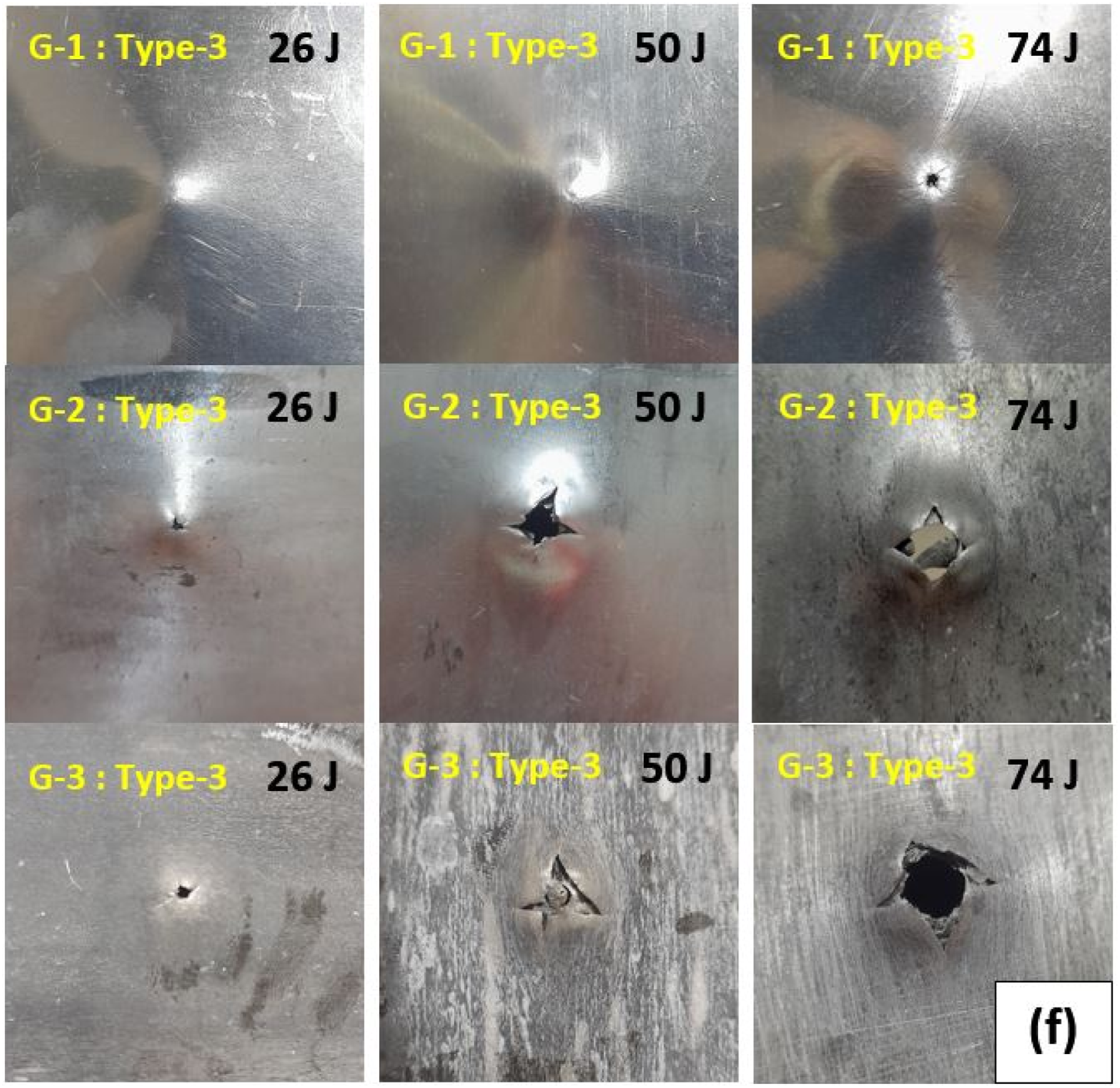


Three sets of samples reinforced with glass, carbon, and hybrid fibers are investigated. Figures 12 to 14 present the front-side damage morphology of the glass, carbon, and hybrid fiber-reinforced samples under the three impact energy levels. Carbon-fiber samples exhibit deeper indentation than the glass and hybrid samples. The extent of dishing around the impact zone is highest in the first group, followed by the second and third groups; however, due to their greater thickness, the first group experiences the least overall damage. Fiber rupture is most pronounced in the third group. Figures 15 and 17 illustrate the rear-side damage characteristics of the glass, carbon, and hybrid specimens. Carbon-fiber specimens show the most severe rear-side damage and crack propagation around the impact zone, followed by the glass and hybrid specimens. Plugging and tearing are mainly observed in the rolled specimens and are absent in the unrolled samples. Moreover, the extent of tearing in the G-2 specimens becomes greater than that in the G-1 specimens.
Figures 18 to 26 present the results obtained from impact tests conducted at energy levels of 26, 50, and 74 joules, displayed as curve plots for each sample group. Type-1, Type-2, and Type-3 samples are represented by red, black, and green curves, respectively. In the displacement-time graphs, the carbon-fiber-reinforced specimens exhibited the highest displacement values, followed sequentially by the glass-fiber-reinforced and hybrid-fiber-reinforced specimens. Additionally, the hybrid-fiber-reinforced specimens exhibited the lowest energy absorption among all tested configurations, indicating a superior capability for both energy storage and dissipating impact energy. This enhanced performance can be attributed to the synergistic interaction between different fiber types, which may contribute to improved damage tolerance. Among the remaining configurations, the Type-2 specimens absorbed more energy than Type-1 specimens, suggesting that their structural composition offers better resistance and more deformation in response to impact-induced failure mechanisms.
Tables 5 to 7 represent the energy absorption results for three groups of specimens under low velocity impact based on 26, 50, and 74 joules. The average mass of the specimens in G-1 was 180 g, significantly higher than those in G-2 and G-3, which weighed 117 g and 120 g, respectively. This difference in mass is primarily attributed to the material composition and layer thickness of each group. The greater mass of G-1 specimens provides a thicker laminate structure, which contributes to enhanced impact resistance and reduced damage under loading conditions. In contrast, the lighter masses of G-2 and G-3 specimens reflect differences in fiber types and plate configurations, potentially influencing their mechanical behavior during impact testing.
The G-1 specimens exhibited the highest peak reaction force during impact, accompanied by the smallest displacement due to their greater plate thickness. In contrast, the G-3 specimens demonstrated a lower peak force and less displacement compared to the G-2 specimens, reflecting a better capacity to rebound impact loads. If the impact of the impactor on an object was not completely inelastic, a portion of its kinetic energy is stored ellastically in the target, subsequently causing the impacting object to rebound. This energy associated with this phenomenon is termed rebound energy. Almost all the FMLs exhibited similar energy absorption levels for a given initial impact energy. However, the SEA differed according to the specimen’s mass. Table 3 displays the energy dissipation results of specimens subjected to low-velocity impact at 26 J. The results show that the G-2 specimens achieved the highest SEA, averaging 221.11 J/kg, followed by the G-3 specimens at 214.83 J/kg, and the G-1 specimens at 143.66 J/kg. Additionally, Tables 6 and 7 present the energy dissipation results of specimens subjected to low-velocity impacts at 50 J and 74 J, respectively. The data indicate that the G-2 specimens have the highest SEA, averaging 422.05 J/kg and 629.66 J/kg at 50 J and 74 J, respectively.
Overall, the rolled specimens exhibited higher SEA compared to the unrolled specimens, primarily due to their reduced mass. When comparing the G-2 and G-3 groups, the G-2 specimens demonstrated superior SEA. Although the incorporation of nanoparticles in the G-3 specimens enhanced the surface hardness of the metal plates, it also contributed to increased crack propagation during failure, and reduced displacement of the metal plates, propelling the projectile back in the oposition direction.
G-1 unrolled FMLs- impact energy: 26 J
Figure 18 shows the plotted response curves of G-1 specimens under 26 J impact energy. The acceleration-time response shows a rapid increase in acceleration immediately after impact due to the sudden contact between the impactor and the laminate surface. The A-C-A configuration exhibits the highest peak acceleration, indicating a stiffer local response associated with the higher modulus of carbon fibers. In contrast, the A-H-A laminate presents a slightly lower peak, suggesting a more progressive load transfer because the hybrid fiber architecture. The subsequent decrease in acceleration reflects the deceleration of the impactor as energy is transferred into laminate deformation and internal damage mechanisms. The velocity-time curves show a monotonic reduction of impactor velocity from the initial impact velocity toward zero. The A-C-A laminate decelerates more rapidly, indicating a higher resistance to penetration and greater stiffness. Conversely, the A-H-A configuration maintains a slightly higher velocity for a longer duration, suggesting more compliant structural behavior and a longer contact duration. The smooth decay of velocity in all configurations indicates that the laminates primarily undergo elastic-plastic deformation and progressive damage without immediate perforation at this energy level. The displacement-time curves illustrate the progressive indentation of the impactor into the laminate. The maximum displacement is highest for the A-C-A laminate, which may be attributed to localized deformation within the composite fiber after the initial high stiffness response. The A-G-A laminate shows slightly lower displacement, indicating relatively balanced stiffness and energy dissipation. The similar shape of the curves suggests that the deformation mechanism is dominated by global bending of the laminate coupled with localized indentation under the impactor. The force-time curves show a typical impact response characterized by a rapid increase in force followed by a gradual decrease as the structure unloads. The A-C-A configuration reaches the highest peak force, reflecting the higher stiffness of carbon fiber reinforcement. The A-H-A laminate exhibits a broader force peak, which indicates more distributed deformation and improved energy dissipation due to the hybrid fiber system. The absence of sudden load drops suggests that catastrophic damage such as fiber bundle rupture or full penetration does not occur at this impact energy. The force-displacement curves reveal the stiffness and damage progression during indentation. The initial slope corresponds to the elastic stiffness of the laminate, where the A-C-A laminate shows the fastest slope. As displacement increases, the curves become nonlinear due to the onset of matrix cracking, interfacial debonding, and localized plastic deformation of the aluminum layers. The A-H-A laminate exhibits a more gradual force evolution, suggesting improved damage tolerance resulting from the hybrid reinforcement. The energy-time curves indicate the progressive absorption of impact energy by the FMLs. All configurations absorb nearly the entire 26 J impact energy, demonstrating that the structures effectively dissipate the kinetic energy through deformation and internal damage mechanisms. The similar final energy levels indicate comparable global energy absorption capacity. However, slight differences in the energy accumulation rate suggest variations in damage initiation and load transfer efficiency among the fiber combinations.
G-2 reinforced rolled FMLs - impact energy: 26 J
Figure 19 illustrates the plotted response curves of G-2 specimens under 26 J impact energy. The acceleration-time curves exhibit the typical bell-shaped impact response associated with contact between the projectile and the FML surface. The AA-C-AA configuration reaches the highest peak acceleration, indicating a higher local stiffness due to the presence of carbon fibers. In comparison, the AA-H-AA laminate shows a slightly lower peak and broader profile, suggesting a more gradual load transfer within the hybrid architecture. The smoother decay of the curves compared with non-rolled laminates indicates a more stable contact interaction due to improved interfacial bonding produced by the rolling process. The velocity-time response demonstrates a continuous decrease in projectile velocity as kinetic energy is transferred to the FML. The AA-C-AA configuration shows the fastest deceleration, reflecting greater impact resistance and higher stiffness of carbon fiber reinforcement. Conversely, the AA-H-AA laminate retains higher velocity for a longer duration, indicating more compliant deformation and slightly longer contact time. The velocity approaches zero for all configurations, confirming that the laminates successfully arrest the impactor without penetration at this energy level. The displacement-time curves illustrate the progressive indentation of the impactor into the laminate. The AA-C-AA laminate exhibits the largest maximum displacement, which suggests localized indentation under the impact point after the initial high stiffness response. The AA-H-AA configuration shows the lowest displacement, indicating improved resistance to indentation possibly due to the more distributed stress field in the hybrid reinforcement. The similar evolution of the curves indicates that deformation is governed by combined global bending and localized indentation mechanisms. The force-time curves demonstrate a rapid increase in contact force followed by gradual unloading as the structure dissipates the impact energy. The highest peak force is observed for the AA-C-AA laminate, reflecting its higher stiffness and load-bearing capacity. The AA-H-AA configuration displays a broader force peak, which indicates a more progressive damage evolution and enhanced energy dissipation through hybrid fiber interaction. The absence of sharp load drops suggests that damage progression remains stable and catastrophic failure does not occur at 26 J. The force-displacement curves reveal the stiffness characteristics and damage development during impact. The initial slope is faster for the AA-C-AA laminate, confirming the higher bending stiffness associated with carbon fibers. As displacement increases, nonlinear behavior appears due to matrix cracking, interfacial debonding, and plastic deformation of the rolled aluminum layers. Compared with non-rolled laminates,the curves exhibit smoother transitions, indicating improved load transfer and reduced delamination due to the rolling process. The energy-time curves indicate that all laminates progressively absorb the entire 26 J impact energy. The similar final energy levels demonstrate that the three configurations have comparable overall energy absorption capacity at this impact level. However, slight differences in the rate of energy accumulation reflect variations in damage initiation and deformation mechanisms among the fiber architectures, with carbon-based laminates absorbing energy more rapidly due to their higher stiffness.
G-3 nanoparticle-reinforced rolled FMLs - impact energy: 26J
Figure 20 depicts the plotted response curves of G-3 specimens under 26 J impact energy. The acceleration response retains the classical bell shape, though with slightly higher and better-defined peaks compared to G-2, due to the stiffening influence of
G-1 unrolled FMLs- impact energy: 50 J
Figure 21 illustrates the plotted response curves of G-1 specimens under 50J impact energy. The 50 J impact level represents a significantly more severe loading condition for unrolled FMLs, pushing the specimens toward higher deformation, extensive matrix cracking, and partial delamination. The following statements describe their dynamic response based on the six classic LVI diagrams. • Acceleration-Time Response
The acceleration profiles demonstrate a clear and sharp rise to a primary peak around 0.002 • Velocity-Time Response
The velocity decreases steadily as the FML absorbs energy. A-C-A decelerates the fastest, consistent with its higher stiffness. A-H-A retains more velocity over time, indicating delayed energy transfer and larger deformation. In all cases, velocity reaches near-zero, confirming complete arrest of the impactor. A small upraising near the end of the curves hints at slight elastic rebound but no significant recovery, consistent with plastic indentation in aluminum sheets. • Displacement-Time Response
A noticeably higher maximum indentation occurs at 50J compared to 26J. A-C-A exhibits the largest peak displacement, surprisingly higher than A-G-A and A-H-A. This indicates that although A-C-A is stiffer, it transfers more load into the aluminum layers, leading to deeper plastic indentation. A-H-A shows the smallest displacement, consistent with improved energy distribution through hybrid layups. The monotonic rise without oscillation suggests; dominant plastic deformation, minimal elastic recovery, and progressive damage accumulation with no sudden instability. • Force-Time Response
At 50J, peak forces increase dramatically. A-C-A reaches the highest peak force at almost 6 kN. A-G-A follows, while A-H-A shows the lowest peak. The curves exhibit; a first peak upper aluminum yielding, a short decline as matrix cracking and local delamination, a second rise for load transfer to the fiber composite, a final sharp drop indicating significant material failure or rapid perforation onset. • Force-Displacement Behavior
The force-displacement curves reveal highest initial stiffness for A-C-A, pronounced nonlinear softening in all laminates, a signature of plasticity together with matrix cracking. A-C-A carries the highest ultimate load, but also demonstrates the most sudden drop, indicating brittle-type failure in composite layers after aluminum yielding. A-H-A shows a smoother force drop, suggesting more stable damage progression. The fast decline at the end implies; extensive delamination, fiber breakage and significant matrix damage. • Energy-Time Response
All laminates absorb nearly the full 50 J. A-C-A absorbs energy more quickly, consistent with stiffer response and larger force peaks. A-H-A absorbs energy more gradually, indicating enhanced damping and distributed damage. A-G-A falls in between, reflecting moderate stiffness characteristics. The uniformity indicates complete arrest of the impactor with no secondary energy input or rebound.
G-2 reinforced rolled FMLs - impact energy: 50 J
Figure 22 depicts the plotted response curves of G-2 specimens under 50 J impact energy. Rolling significantly increases the yield strength, hardness, and stiffness of the aluminum layers, producing a more stable and higher-capacity response under dynamic impact. At 50 J, these enhancements become clearly distinguishable when compared to the G-1 group. • Acceleration-Time Response
The acceleration plots show well-defined peaks with reduced oscillation compared to G-1, reflecting the stabilizing effect of rolled aluminum sheets. Observed characteristics; AA-C-AA shows the highest peak acceleration, confirming the largest stiffness among the three laminates. AA-H-AA exhibits a slightly broader and smoother response, indicating improved damping from the hybrid laminate. All curves show a small secondary peak, representing progressive damage events due to matrix cracking and initial delamination. Rolling decreases noise and oscillation amplitude, evidencing higher structural integrity, more uniform stress transfer, and delayed instability in composite-metal interfaces. • Velocity-Time Response
The velocity fall patterns for all three laminates are very similar, with a gradual reduction around 4.5 m/s to near zero. AA-C-AA decelerates slightly faster, consistent with its higher stiffness. AA-H-AA retains velocity longer, suggesting smoother load distribution. The absence of significant rebound indicates; no perforation, full arrest of the impactor, dominant plastic indentation without recovery. • Displacement-Time Response
The displacement curves show noticeable improvement compared to non-rolled G-1 laminates. Lower maximum displacement overall, due to increased metallic layer hardness from rolling. AA-C-AA shows the smallest displacement, confirming superior resistance to bending and indentation. AA-H-AA exhibits a slightly higher displacement, attributed to hybrid laminate agreement. The monotonic form with no oscillation illustrates; stable plastic deformation, restricted transverse vibration, no severe global bending. • Force-Time Response
Rolling significantly elevates the load-carrying capacity. Peak forces approach 5 kN, slightly lower than G-1 carbon but with much smoother evolution. AA-H-AA surprisingly shows a high intermediate peak, indicating improved energy dissipation through hybridization. Key observations including the force-time curves exhibit a two-stage rise. Stage one for yielding of the rolled aluminum and stage two for load transfer to the composite fiber. The unloading slope is smoother, pointing out that less catastrophic damage, more controlled failure, and better crack arresting capability in rolled interfaces. The absence of a sharp final drop, compared to G-1, shows enhanced structural stability. • Force-Displacement Response
This is one of the most illustrative diagrams. AA-C-AA has the highest initial stiffness and the largest ultimate load. Curves show reduced nonlinearity, demonstrating improved resistance to plastic deformation. AA-H-AA shows the smoothest force reduction, confirming greater ductility, better energy spreading, and delayed matrix cracking. Rolling noticeably shifts the entire F-x curves upward, representing an overall higher load-bearing capacity and reduced indentation depth. • Energy-Time Response
All laminates successfully absorb the full 50 J energy. AA-C-AA absorbs energy at the fastest rate, matching its higher stiffness. AA-H-AA shows the most gradual absorption, consistent with distributed damage and effective damping. The plateau at the end confirms complete impactor arrest with no rebound or reloading.
G-3 nanoparticle-reinforced rolled FMLs - impact energy: 50J
Figure 23 shows the plotted response curves of G-3 specimens under 50 J impact energy. Adding • Acceleration-Time Response
Acceleration curves show strong increment due to nanoparticle reinforcement. AAA-C-AAA exhibits the highest peak acceleration, substantially above the others. This reflects the most rigid laminate architecture. AAA-G-AAA shows a moderate peak, consistent with intermediate stiffness. AAA-H-AAA displays the lowest and smoothest acceleration profile, indicating greater damping and more distributed damage. A notable feature is the secondary peak in AAA-C-AAA and AAA-G-AAA. These correspond to rapid damage propagation events. Likely matrix cracking, localized delamination, and transition to aluminum plasticity. Nanoparticles improve interfacial strength, but at high energy, their stiffening effect makes the structure more sensitive to shock accelerations. • Velocity-Time Response
Velocity decreases smoothly in all FMLs until complete arrest. AAA-C-AAA decelerates the fastest, consistent with its greatest stiffness. AAA-H-AAA retains velocity longer, meaning more gradual energy dissipation. No significant rebound is observed. This behavior confirms enhanced impact-energy absorption along with more controlled deceleration compared to G-1 and G-2. • Displacement-Time Response
The AAA-C-AAA sample shows the smallest peak displacement about 0.024 m region, confirming its superior indentation resistance. AAA-G-AAA follows, slightly higher displacement. AAA-H-AAA has the largest displacement, consistent with its hybrid composite fiber and lower stiffness. Compared to G-1 and G-2; G-3 exhibits lowest indentation at the same energy. Nanoparticles effectively suppress plastic indentation and stabilize bending response. • Force-Time Response
The force response for G-3 shows strong improvement in load-carrying capacity. AAA-C-AAA again shows the highest peak force about 5 kN. AAA-G-AAA follows, slightly lower. AAA-H-AAA shows the lowest, but still higher than its G-1 and G-2 counterparts. Important features for this section consist of a clearly visible multi-stage force evolution. Stage 1: aluminum elastic and early yielding, stage 2: composite engagement plus matrix cracking, stage 3: nanoparticle surface reduces crack propagation, and stage 4: gradual unloading with less catastrophic drop. AAA-H-AAA shows smoother unloading, meaning more ductile and distributed damage. Compared to G-2: Rolling with nanoparticles increase the peak load by up to 10-15%. Damage becomes more controlled and less unexpected. • Force-Displacement Response
This is one of the clearest demonstrations of the advantage of G-3. AAA-C-AAA has the highest initial slope, highest peak force, and lowest displacement. It shows the best structural efficiency so far. AAA-G-AAA sits between the two, reflecting moderate stiffness and good toughness. AAA-H-AAA shows the smoothest curve, with smaller force peaks but much more stable deformation. Nanoparticles significantly reduce mid-region nonlinearity, local softening, and premature failure of composite layers. The curves indicate high resistance to both bending and indentation, even near the perforation threshold. • Energy-Time Response
All laminates successfully absorb the full impact energy. AAA-C-AAA accumulates energy fastest, indicating dominating stiffness. AAA-H-AAA absorbs energy more gradually, reflecting higher damping. The plateau region is smooth and stable, meaning that there is no rebound, no sudden unloading, and damage is progressive, not catastrophic. Compared to G-1 and G-2: - G-3 shows the most stable and efficient energy absorption profile. Nanoparticles contribute substantially to the resilience of the aluminum-composite interface.
G-1 unrolled FMLs- impact energy: 74 J
Figure 24 shows the plotted response curves of G-1 specimens under 74 J impact energy. At an impact energy of 74J, the G-1 laminates enter a near-perforation deformation regime, where structural behavior is dominated by severe plastic bending, extensive matrix cracking, and interfacial delamination. Differences between laminate architectures become less pronounced compared to lower energies, as the system response is governed primarily by large-scale metallic yielding. • Acceleration-Time Response
All laminates exhibit a pronounced single acceleration peak of approximately 1000 • Velocity-Time Response
The impactor velocity decreases smoothly from almost 4.4 m/s to nearly zero. All three laminates show almost identical deceleration profiles, indicating that differences in fiber type have limited influence at this energy level. A slight negative velocity at the end suggests a minimal rebound, confirming complete impactor arrest, and high plastic indentation without perforation. The absence of abrupt velocity fluctuations implies that the deformation process is governed by non-elastic, and large-deflection bending rather than brittle failures. • Displacement-Time Response
Maximum displacement reaches approximately 0.02-0.021 m, placing the laminates near their indentation capacity. A-C-A exhibits the smallest peak displacement, reflecting greater structural rigidity due to the carbon fiber. A-H-A shows the highest displacement, consistent with lower stiffness and increased compliance. The displacement curves form a plateau near the end, indicating full arrest of the impactor and stabilization of permanent deformation. The close vicinity of the three curves reflects the dominant role of plastic bending at high energies. • Force-Time Response
The force response reveals significantly increased load capacity relative to lower energies. Peak forces reach almost 8 kN. A-C-A displays the highest peak load, aligning with its higher stiffness. A-H-A has the lowest peak, due to more compliant hybrid reinforcement. The force rise is nearly linear until the peak. After the maximum load: A sharp force drop is observed in all laminates. This rapid unloading indicates severe delamination, extensive aluminum yielding, and local damage propagation. This behavior is characteristic of laminates operating near the penetration threshold. • Force-Displacement Response
The F-x curves illustrate the global deformation mechanics clearly. High initial stiffness, especially for A-C-A. A gradual increase in force up to 8000 N. A sudden post-peak drop, indicating structural softening due to matrix cracking, local buckling of metal layers, and interfacial degradation. The close grouping of curves again confirms that fiber type effects diminish at high energy, as aluminum dominates the load response. • Energy-Time Response
Energy absorption increases steadily and approaches 72-74 J. Confirming: no perforation, nearly complete absorption of impact energy, predominantly plastic response without significant elastic return. The curves of all three laminates overlap almost perfectly, indicating that the energy absorption mechanism is governed almost entirely by metallic deformation rather than composite behavior.
G-2 reinforced rolled FMLs - impact energy: 74J
Figure 25 illustrates the plotted response curves of G-2 specimens under 74J impact energy. At an impact energy of 74J, the rolled FML laminates experience severe deformation approaching the penetration threshold. However, compared with non-rolled laminates, the rolling process improves structural integrity by increasing the yield strength of aluminum layers and promoting more stable energy dissipation. • Acceleration-Time Response
The acceleration response shows peak values of approximately 680-750 • Velocity-Time Response
The impactor velocity decreases from approximately 4.4 m/s to near zero. Important features: AA-C-AA decelerates more rapidly, consistent with its higher stiffness and load-bearing capacity. AA-H-AA maintains slightly higher velocity for a longer duration, indicating more gradual energy absorption. All laminates show very small negative velocities at the end, indicating a slight rebound after impact. • Displacement-Time Response
Maximum displacement ranges approximately between 0.020 and 0.024 m. Observed trends: AA-C-AA shows the smallest displacement, reflecting its higher bending stiffness. AA-H-AA exhibits the lowest final displacement in the figure due to earlier unloading, indicating partial recovery after peak deformation. AA-G-AA reaches the largest displacement, suggesting greater ductility and plastic deformation capacity. Compared with G-1 laminates, the displacement curves are slightly more stable, indicating improved structural resistance due to the rolling process. • Force-Time Response
The force-time curves display peak forces of approximately 5.3-5.7 kN. Key findings: AA-C-AA reaches the highest peak force, consistent with the stiffness of carbon fibers. AA-H-AA exhibits the lowest peak force, due to greater structural compliance. The loading phase shows a nearly linear increase in force followed by a rapid drop, indicating the onset of severe internal damage. Compared with G-1 laminates: the force histories are smoother and more stable, indicating improved load distribution and delayed catastrophic damage propagation. • Force-Displacement Response
The force-displacement curves reveal clear nonlinear deformation behavior. Main characteristics: higher initial stiffness for AA-C-AA, resulting in a faster initial slope. Maximum forces occur at displacements of approximately 0.02-0.022 m. After the peak load, the curves show a rapid drop, corresponding to extensive delamination and plastic collapse. AA-G-AA shows the largest deformation capacity, suggesting improved ductility. • Energy-Time Response
Energy absorption increases steadily and approaches 74J for all FMLs. Important observations: AA-C-AA absorbs energy more rapidly in the early stage, due to its higher stiffness. AA-H-AA shows a slightly delayed energy absorption, indicating more gradual damage progression. Eventually, all curves converge, confirming that the entire impact energy is absorbed by the laminate system.
G-3 nanoparticle-reinforced rolled FMLs - impact energy: 74J
Figure 26 shows the plotted response curves of G-3 specimens under 74 J impact energy. At an impact energy of 74J, the G-3 laminates exhibit severe deformation but maintain improved structural stability due to the combined effects of rolling and ceramic particle reinforcement. The presence of • Acceleration-Time Response
The acceleration curves reach peak values of approximately 560-630 • Velocity-Time Response
The impactor velocity decreases from approximately 4.4 m/s to nearly zero. Important trends: AAA-C-AAA shows the fastest velocity decay, consistent with its higher stiffness and load-bearing capacity. AAA-H-AAA retains slightly higher velocity for a longer duration, indicating a more gradual energy dissipation process. Near the end of the impact event, velocities approach zero with minimal rebound, confirming efficient energy absorption without complete penetration. • Displacement-Time Response
The maximum displacement ranges approximately between 0.02 and 0.028 m. Observations: AAA-C-AAA shows the largest displacement, which suggests that although the laminate is stiff, the energy is dissipated through larger plastic deformation before unloading. AAA-H-AAA exhibits the smallest displacement, indicating improved deformation control due to hybrid reinforcement and particle strengthening. AAA-G-AAA demonstrates intermediate behavior, balancing stiffness and deformation capacity. Compared with G-1 and G-2 specimens, the displacement curves show more gradual evolution, indicating more stable structural deformation. • 4. Force-Time Response
The force-time curves show peak forces of approximately 4.3-4.8 kN. Key features: AAA-C-AAA reaches the highest peak force, reflecting the higher stiffness of the carbon-fiber configuration. AAA-H-AAA shows the lowest peak force, due to its greater compliance. After the peak load, the force decreases rapidly, indicating the onset of extensive internal damage such as: matrix cracking, delamination, and plastic deformation of aluminum layers. However, compared with previous groups, the force histories remain relatively smooth, indicating controlled damage propagation. • Force-Displacement Response
The force-displacement curves exhibit a nonlinear response characteristic of progressive damage. Main characteristics: Initial stiffness is highest for AAA-C-AAA. Peak force occurs at displacements around 0.020-0.023 m. Following the peak, a rapid force drop indicates structural softening caused by delamination and plastic collapse. The smoother curve shapes suggest that particle reinforcement promotes gradual damage evolution rather than abrupt failure. • Energy-Time Response
Energy absorption increases steadily and approaches approximately 72-74 J for all laminates. Important observations: AAA-C-AAA absorbs energy slightly faster during the early stage, due to higher stiffness. AAA-H-AAA exhibits a more gradual energy absorption rate, indicating progressive deformation and damage development. All curves converge at the end, confirming that the laminates absorb nearly the entire impact energy.
Tables 5 to 7 show the energy dissipation results for three groups of specimens under low velocity impact based on U(J) = 26, 50, and74, respectively. A phenomenological comparison is conducted to evaluate the influence of rolling and particle reinforcement on the impact performance of the investigated FMLs. The G-1 laminates (unrolled FMLs) exhibit the lowest structural stability under impact loading. Due to the lower yield strength of the aluminum layers, plastic deformation occurs relatively early during the impact event. As a result, the laminates show higher displacement values and less stable force responses, particularly at higher impact energies. Damage propagation in this group is dominated by early delamination and matrix cracking. The G-2 laminates (rolled FMLs) demonstrate improved impact resistance compared with the non-rolled laminates. The rolling process increases the yield strength of the aluminum layers through work hardening, which enhances the stiffness and load-bearing capacity of the laminate system. Consequently, higher peak forces and more stable force-time responses are observed. In addition, the deformation is slightly reduced and the energy dissipation process becomes more gradual. The G-3 laminates (rolled FMLs reinforced with
The general trends observed in the present work are consistent with the behavior reported for conventional FML systems under low-velocity impact loading. Previous studies have shown that variations in face sheet thickness, fiber architecture, and interfacial properties significantly influence the impact resistance and energy absorption capability of FML structures. The current results similarly demonstrate that increasing the stiffness of the aluminum layers and modifying the fiber configuration strongly affect the deformation mechanisms and energy dissipation behavior of the laminates. In particular, the reduced displacement and improved rebound behavior observed in nanoparticle-reinforced laminates are consistent with the increased elastic stiffness of the metal layers. However, Yu et al. 4 investigated applicability of carbon fiber in FMLs and the effect of the properties of aluminum alloy on the low velocity impact response based on different aluminum alloys, namely 1060-O, 2024-T3, 6061-T6 and 7075-T6. Based on the load-time relations of CARALL and Glare with impact energies of 20J, 30J and 50J showed on the figure in Yu et al. 4 : For example, comparative investigations between CARALL and GLARE laminates have shown in Yu et al. 4 that carbon-fiber-based FMLs generally exhibit higher peak loads, shorter contact times, and smaller central deflections due to their higher stiffness and strength under low-velocity impact loading. A similar trend was observed in the present work, where laminates with higher stiffness demonstrated improved impact resistance and reduced deformation. This agreement indicates that the impact response obtained in this study follows the fundamental mechanical behavior commonly reported for fiber-metal laminates.
Numerical results
In experimental tests or simulations, plotting internal energy versus time or displacement provides insight into the extent of energy absorption. When a structure is subjected to a low-velocity impact, typically less than 10 m/s, the load-displacement response and internal energy absorption are key indicators of its performance. These parameters not only characterize the structural performance but also provide insight into damage initiation, propagation, and failure mechanisms. In the load-displacement graph, the contact force increases with displacement, and the peak load appears at the maximum stiffness or the onset of damage. After impact, an unloading phase appears. If damage such as plastic deformation, cracking, or delamination develops, the unloading slope becomes more gradual, representing energy loss. Under dynamic loading, internal energy refers to the total energy absorbed, stored, or dissipated within the specimen due to deformation. In a finite element simulation, this response is typically decomposed into elastic strain energy, plastic dissipation, and damage energy. At a glance, the total internal energy corresponds to the area under the force-displacement curve and represents the absorbed energy. Higher internal energy generally indicates greater permanent damage or plastic work, unless the energy is primarily stored elastically. It also reflects a higher energy absorption capability, which is beneficial in applications requiring energy dissipation, such as protective structures. However, it may also imply more severe internal damage, potentially reducing long-term structural integrity.13,55,56
The G-1 group specimens with facesheet thicknesses of 2 mm and 1 mm are simulated using three fiber types and subjected to impact energies of 26 J, 50 J, and 74 J as shown in Figures 27 to 32. At 26 J impact energy and 2 mm facesheet specimens, the internal energy ranges from 20.9 J to 21.12 J, and the projectile displacement varies from 9.2 mm to 9.6 mm. The carbon-type FML absorbed more energy and exhibited larger displacement than the others, while the hybrid-type FML shows the lowest energy absorption and displacement. For the 1 mm specimensat the same impact energy, the internal energy ranges from 21.94 J to 22.05 J, and the projectile displacement varies from 11.9 mm to 12.3 mm. Similarly, the carbon-type FML absorbed more energy and displacement than the others, whereas the hybrid-type FML absorbed the least. Comparable trends are observed at impact energies of 50 J and 74 J for both the carbon and hybrid samples. At 50 J, the highest absorbed energy is 42.81 J with a displacement of 13.5 mm, while the lowest energy absorbed becomes 41.76 J with a displacement of 12.8 mm. At 74 J, the highest absorbed energy reachs to 65.59 J with a displacement of 16.4 mm, and the lowest absorbed energy is 63.99 J with a displacement of 15.7 mm. Simulation response of G-1 & type-1 specimens. Simulation response of Al-Glass-Al-1 mm specimens. Simulation response of G-1 & type-2 specimens. Simulation response of Al-Carbon-Al-1 mm specimens. Simulation response of G-1 & type-3 specimens. Simulation response of Al-Hybrid-Al-1 mm specimens.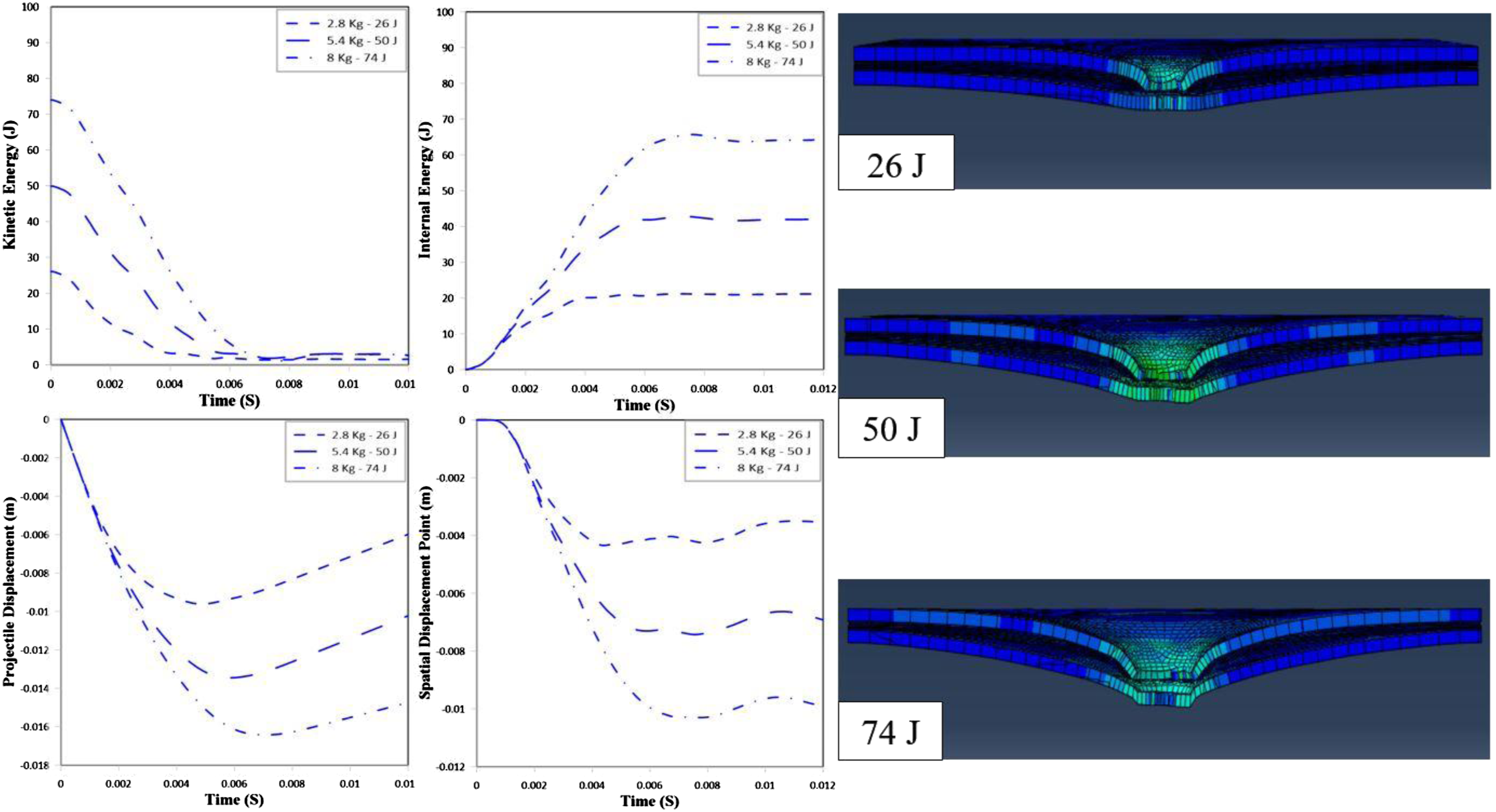
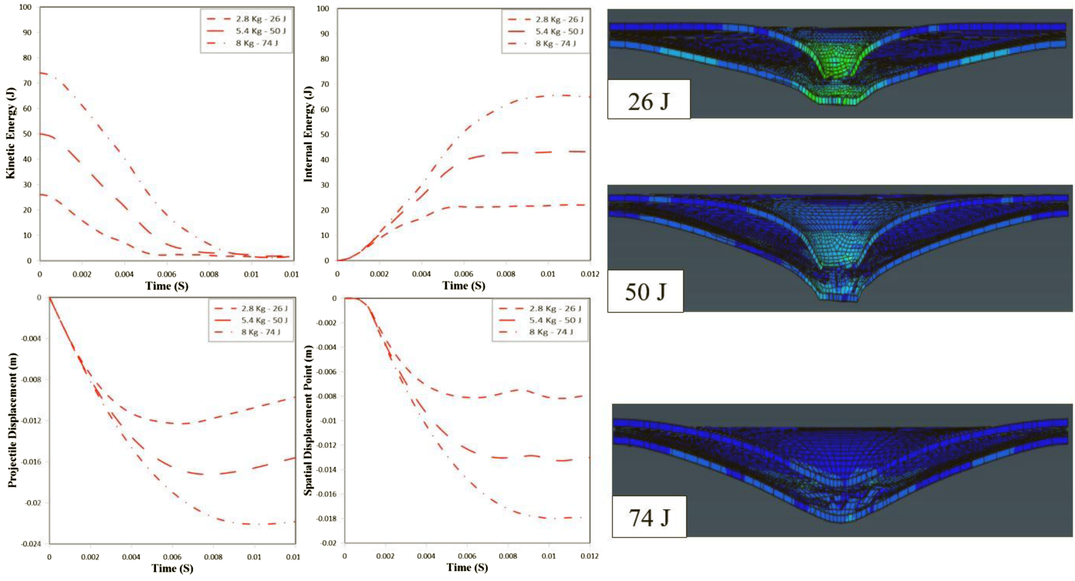
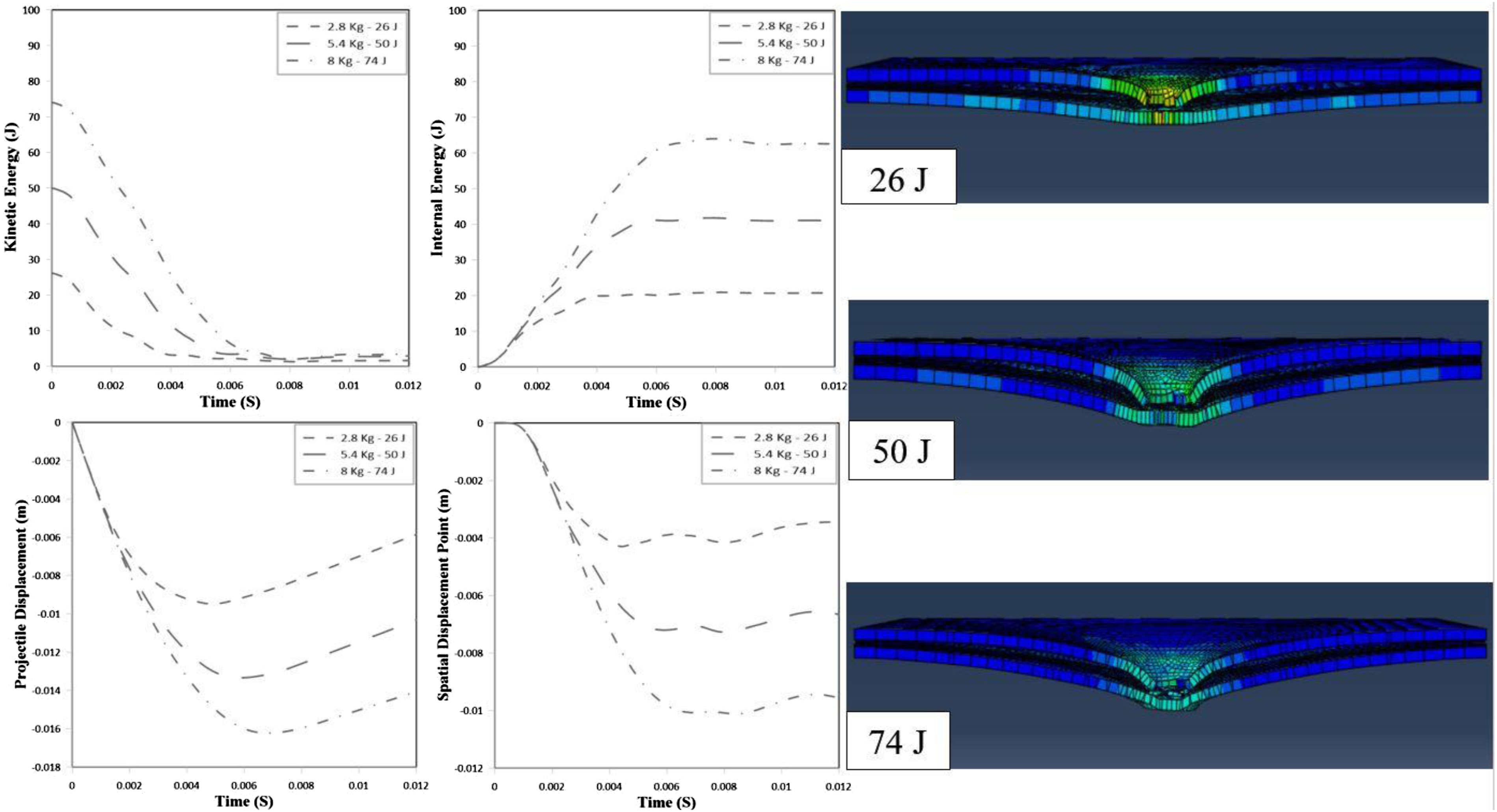
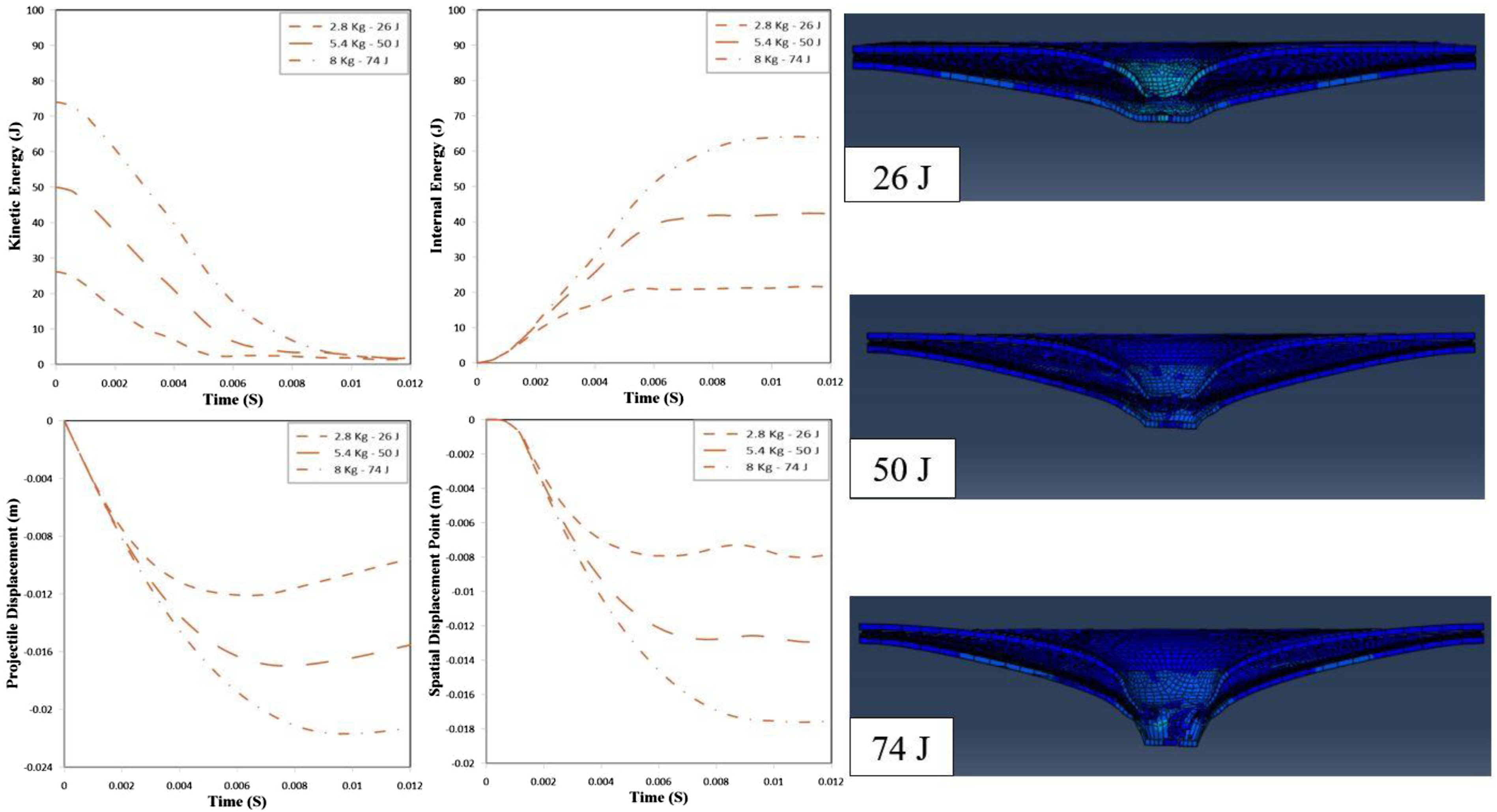
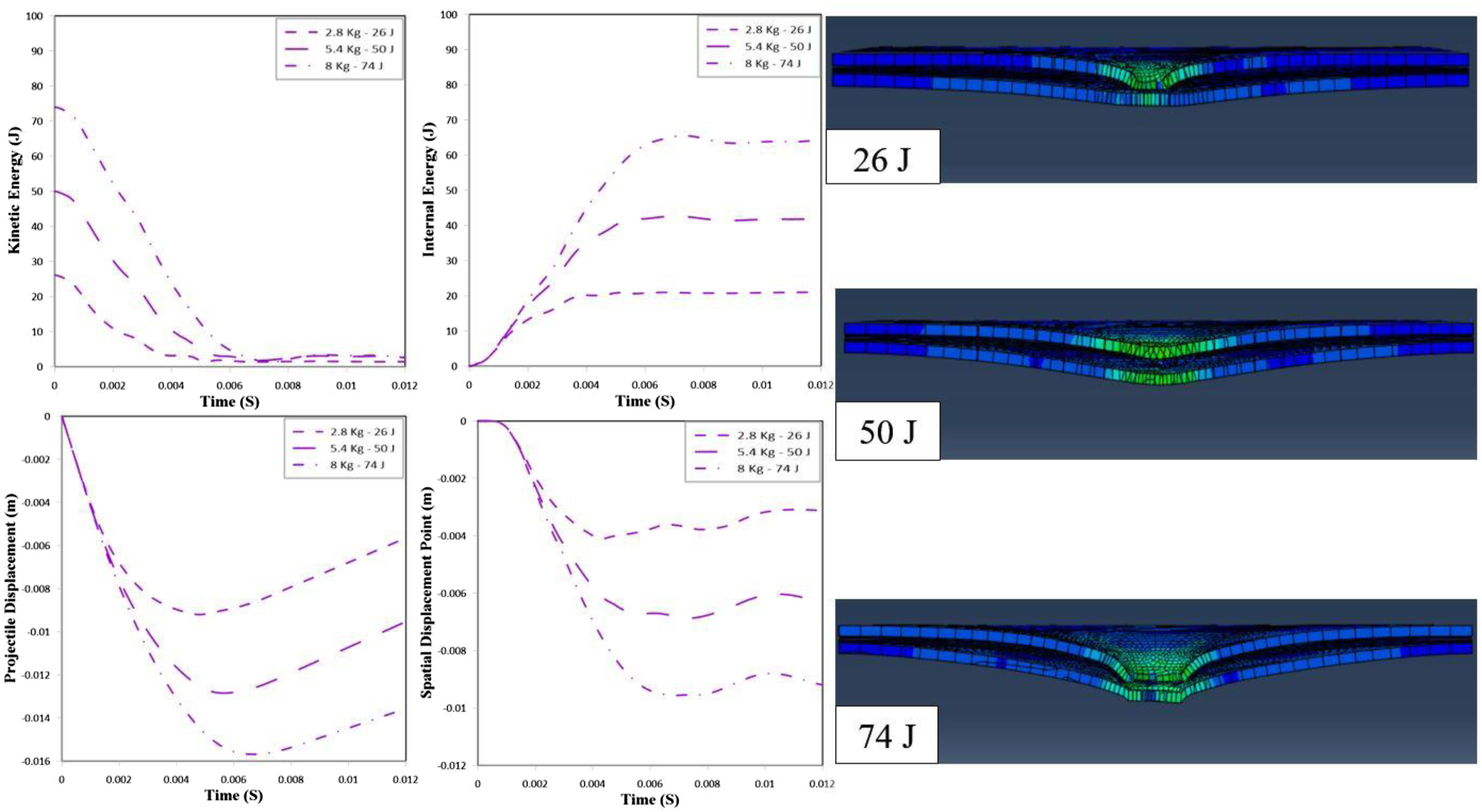
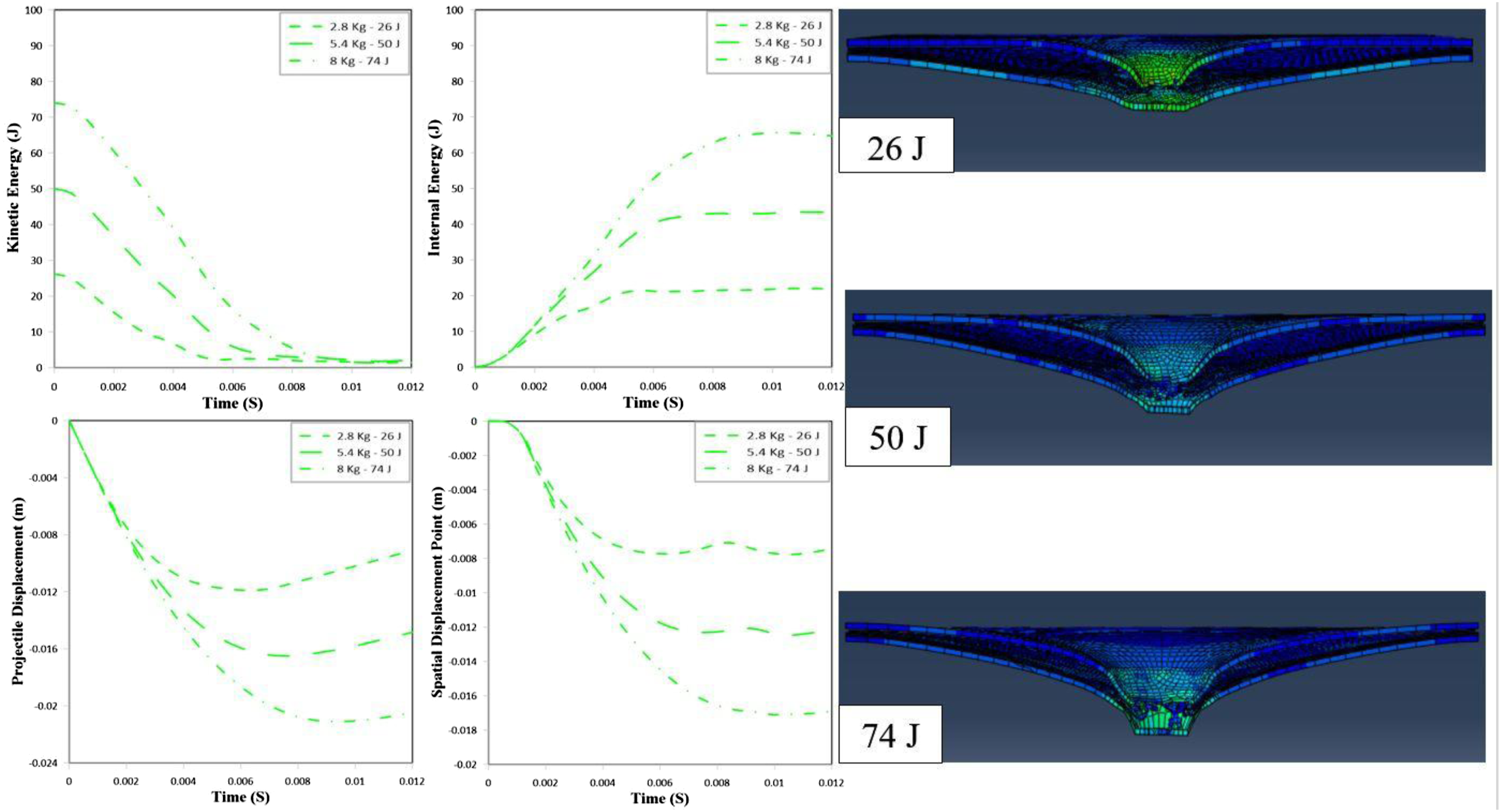
Comparing the simulation results for G-1 type-1 and Al-1 mm/Glass-4 layers/Al-1 mm without including rolling effects is shown in Figures 27 and 28, respectively that is explained as follows: • Kinetic Energy-Time Response
Across both thickness configurations, the kinetic energy curves show the classical exponential-like decay characteristic of explicit impact simulations. At first, 26 J loses most of its kinetic energy around 3.5-4.0 ms. Then, 50 J reaches near-zero kinetic energy at 5.0-5.5 ms. Next, 74 J extends up to 6.0-6.5 ms. This consistent increase in decay duration reflects a transition from non-penetrating deformation at 26 J to deep indentation approaching perforation at 74 J.
The thicker aluminum skins exhibit earlier kinetic energy dissipation, sharper decay rate, and more rapid momentum transfer. Because the thicker face sheets carry higher bending stiffness, they absorb and distribute the impact impulse more effectively. In contrast, the 1 mm aluminum layers show slower KE reduction, longer projectile-panel contact time, and larger residual oscillations after the main impact event. This indicates weaker structural restraint and greater local indentation. • Internal Energy-Time Response
Internal energy grows monotonically for all impacts, expected for a purely dissipative FMLs in explicit dynamics. For both configurations, 26 J reaches almost 18-22 J, then 50 J rises toward 38-45 J, and 74 J approaches around 65-70 J. This is consistent with well-captured energy balance in ABAQUS. The thicker metal configuration shows lower final internal energy for each impact energy. Part of the energy is stored elastically in bending and membrane action of the stiffer face sheets instead of being dissipated as plastic/viscoelastic damage in the laminate. The 1 mm metal configuration shows higher internal energy accumulation and longer growth period. It represents a more damage-dominated regime involving higher plastic strain, fiber-matrix shear damage, and larger delamination propagation due to lower bending rigidity. • Projectile Displacement-Time Response
Projectile displacement curves clearly separate based on impact energy. 26 J results in partial indentation with rebound beginning near 4 ms 50 J penetrates deeper, approaching twice the displacement of 26 J 74 J yields the largest displacement, with no rebound trend, indicating near-perforation behavior. Thicker aluminum exhibits significantly smaller peak displacement, sharper deceleration, and earlier stabilization. Thinner aluminum shows deeper penetration, especially at 50 J and 74 J. Displacement curves continue descending for a longer time, confirming insufficient stiffness to resist indentation. This comparison directly validates the bending stiffness dominance in symmetric FMLs under localized impact. • Special Displacement Point-Time (Back-Face Deflection)
This quantity is essential for evaluating back-face bulging, which governs perforation resistance and minimum impulse required for plugging. Back-face motion behavior for both thicknesses at 26 J shows minor downward displacement which is fully recoverable. At 50 J pronounced downward bending which reacts partial recovery. At 74 J illustrates deepest back-face deformation which responds almost without recovery. This perfectly correlates with the strain patterns in the right-side deformation images. With 2 mm aluminum, back-face deflection is smaller and smoother, oscillations are less severe, and stiffness mitigates through-thickness wave transmission. With 1 mm aluminum, deflection depth roughly twice to that of the 2 mm case. The downward curvature is sharper, indicates higher bending and lower delamination resistance. Thus, the back-face deflection curve is the clearest indicator of bending stiffness differences between the two configurations. • Correlation With FEM Deformation Images
The images on the right are fully consistent with all four curves. At 26 J shows smooth dome-shaped indentation, limited fiber shear distortion, no back-face folding. At 50 J core region depicts dense element distortion, lower metal layer visibly deflects downward, and energy absorption dominated by metal plasticity. At 74 J displays severe indentation, severe deformation beneath impact point. The 1 mm aluminum case visibly exhibits deeper indentation, greater back-face deformation, and more localized curvature.
Evaluating the simulation results for G-1 type-2 and Al-1 mm/Carbon-4 layers/Al-1 mm without including rolling effects is shown in Figures 29 and 30, respectively that is explained as follows: • Kinetic Energy-Time Response
The kinetic energy histories for Carbon Fiber FMLs exhibit a rapid and efficient decay, highlighting the high stiffness and strong load-transfer capability of carbon fibers. At 26 J, the kinetic energy decreases rapidly and nearly vanishes within approximately 3.5-4.0 ms. At 50 J, the duration extends to around 5.0-5.5 ms. At 74 J, the decay time further extends to around 6.0-6.5 ms, reflecting greater structural deformation and longer interaction between the projectile and the panel. The 2 mm aluminum configuration consistently shows a faster rate of kinetic energy dissipation than the 1 mm counterpart, owing to its higher bending stiffness that enables a more efficient redistribution of impact loads. The thinner aluminum sheets cause a more gradual decay, implying extended structural vibration and localized deformation. Compared to Glass FMLs (Group1), the carbon fiber laminates reveal a slightly quicker KE reduction, confirming the stiffening effect of the carbon plies under high-rate loading. • Internal Energy-Time Response
The internal energy evolution curves demonstrate a smooth increase followed by a attained stage, representing the amount of absorbed impact energy through both plastic and damage mechanisms. At 26 J, the final internal energy stabilizes around 20-25J. At 50J, it grows to approximately 40-45J. At 74J, it reaches its ultimate value of 60-70J. The 1 mm aluminum configuration consistently stores more internal energy, indicating that thinner metallic skins undergo more substantial plastic deformation as well as matrix cracking, fiber-matrix shear damage, and interfacial debonding. In contrast, the 2 mm aluminum configuration stores less internal energy because a larger fraction of the impact is managed by elastic bending and membrane action before yielding predominates. • Projectile Displacement-Time Response
Projectile displacement reflects the panel’s penetration resistance and overall impact protection capacity. At 26 J, the displacement is minimal, and minor rebound appears around 4 ms. At 50 J, a notable increase in displacement is shown, indicating deeper indentation. At 74 J, the displacement peaks, approaching the perforation limit of the structure. Across all impact energies, the 2 mm aluminum skins demonstrate smaller peak displacements than the 1 mm configuration. It emphasizes their superior bending rigidity and ability to diffuse the contact load through the laminate. The response of the 1 mm aluminum panels shows a greater indentation depth, confirming that metal thickness strongly governs penetration resistance. Relative to the glass-fiber laminates, the carbon fiber FMLs show smaller projectile displacements, derived from their higher in-plane modulus and stiffness. • Back-Face Deflection Response
The back-face deflection data provide further insight into through-thickness bending and rear-surface behavior. At 26 J, deflection remains low and primarily elastic. At 50 J, noticeable bending deformation develops. At 74 J, maximum deflection occurs, with large irreversible bending and local stretching near the punching region. The 1 mm aluminum configuration displays significantly higher back-face deflection at each energy level, indicating its lower bending stiffness and less effective stress distribution. Conversely, the 2 mm configuration shows more constrained out-of-plane motion, signifying stiffer structural behavior and more effective impact load spreading across the panel. • Correlation with Deformation Contours
The deformation contours generated in ABAQUS simulations validate the above observations. At 26 J: Deformation remains localized below the impactor, forming a little depth and symmetric dent. At 50 J: The affected zone expands, and bending of the lower aluminum ply becomes visible, more pronounced in the 1 mm configuration. At 74 J: Severe indentation develops, with an evident large deformation profile; the 1 mm aluminum case experiences deeper curvature and more pronounced back-face deformation, approaching failure conditions.
Assessing the simulation results for G-1 type-3 and Al-1 mm/Hybrid-4 layers/Al-1 mm without including rolling effects is shown in Figures 27 and 28, respectively that is explained as follows:
The hybrid laminate combines the high stiffness of carbon fibers with the higher strain-to-failure of glass fibers, which is expected to produce a balanced impact response between stiffness and energy absorption. • Kinetic Energy-Time Response
The kinetic energy histories demonstrate a rapid transfer of projectile energy to the hybrid FML, followed by progressive energy dissipation due to plastic deformation and composite damage. For both configurations: At 26 J, the kinetic energy decreases rapidly and approaches zero within approximately 4 ms. At 50 J, the interaction duration increases to about 5-6 ms. At 74 J, the decay period extends to nearly 6-7 ms, reflecting more severe deformation and longer contact time. The 2 mm aluminum configuration shows a slightly faster decay in kinetic energy compared with the 1 mm configuration. This indicates that the increased bending stiffness of the thicker metal skins enhances the structural ability to redistribute impact loads. In contrast, the 1 mm aluminum laminate exhibits a more gradual KE reduction, implying greater localized deformation and longer vibration of the panel. Overall, the hybrid laminate shows a kinetic energy dissipation rate intermediate between Glass FML and Carbon FML, which confirms the balancing effect of combining both fibers. • Internal Energy-Time Response
The internal energy curves increase steadily with time until reaching a plateau, representing the absorbed portion of the impact energy. The final absorbed energy levels are approximately: At 26 J initial impact is about 18-20 J, at 50 J impact is around 40-42 J, and at 74 J impact is closed to 63-66 J. As observed in the previous groups, the 1 mm aluminum configuration absorbs slightly more internal energy. This behavior indicates that thinner metal skins undergo more extensive plastic deformation and allow additional energy dissipation through composite damage mechanisms such as fiber fracture, matrix cracking, and interlaminar delamination. The 2 mm configuration, due to its higher stiffness, stores slightly less internal energy but distributes stresses more efficiently across the laminate. • Projectile Displacement-Time Response
The projectile displacement histories reveal the penetration resistance of the hybrid laminate. For all impact energies, displacement increases with increasing energy: At 26 J, penetration depth remains small and partial rebound of the projectile begins after approximately 4-5 ms. At 50 J, the projectile penetrates deeper before slowing down. At 74 J, the maximum displacement is observed, approaching the structural resistance limit. The 2 mm aluminum skins consistently produce smaller projectile displacements, confirming that higher metal thickness improves indentation resistance. The 1 mm configuration, on the other hand, allows greater indentation depth due to its lower bending stiffness. When compared with the previous groups, hybrid FML shows smaller displacement than Glass FML but slightly larger displacement than Carbon FML. • Back-Face Deflection Response
Back-face deflection curves show the out-of-plane deformation of the rear aluminum sheet. The response follows the same general trend: Small and mostly elastic deflection occurs at 26 J. Moderate bending deformation take placed at 50 J. Significant permanent deformation observed at 74 J. The 1 mm aluminum configuration shows larger back-face displacement due to reduced bending rigidity. Conversely, the 2 mm configuration demonstrates smaller rear-surface deflection, indicating more efficient load spreading and improved structural stiffness. However, compared to Carbon FML, the hybrid laminate exhibits slightly larger back-face deflection, which can be attributed to the presence of glass fibers with lower modulus. • Correlation with Deformation Contours
The deformation contours observed in the ABAQUS simulations strongly support the numerical results. At 26 J, deformation is localized near the impact point with a small indentation and minimal rear-surface bending. At 50 J, the deformation zone expands significantly, and bending of the lower aluminum layer becomes clearly visible. At 74 J, severe indentation occurs, and the laminate develops a pronounced conical deformation profile beneath the impactor. The deformation pattern remains symmetric, and the hybrid laminate shows a smoother transition of deformation compared with pure carbon laminates due to the improved strain capacity of glass fibers.
Simulation results under low velocity impact based on initial impact energy, U(J) = 26.

The internal energy values demonstrate relatively small variation among specimens, ranging from 21.57 J to 22.05 J with the highest value recorded in the G-2 laminate with carbon fiber reinforcement. The lowest energy absorption is observed in the G-3 laminate with hybrid fibers. These results suggest that, although overall energy absorption capability remains consistent across laminate types, the mechanism of energy dissipation differs based on aluminium treatment and fiber reinforcement. Notably, the G-3 specimens, with alumina-reinforced aluminium, exhibit slightly lower energy absorption, reflecting reduced plastic deformation and enhance rigidity due to the nanoparticle reinforcement. Impactor displacement values ranged from 11.4 mm to 12.3 mm, with the maximum value occurring in the G-2 carbon fiber specimen, while the minimum value is consistently recorded in G-3 laminates, particularly the hybrid fiber-reinforced variant. These results highlight that nanoparticle-enhanced aluminium resists indentation and penetration more effectively, indicating greater surface rigidity and structural resistance to compressive loads. G-1 and G-2 specimens allow slightly more deformation under impact, consistent with the more ductile nature of pure and rolled aluminium. In terms of spatial displacement, the downward deflection of the bottom aluminium face sheet ranged between 7.5 mm and 8.2 mm. The greatest flexural displacement (8.2 mm) is again observed in the G-2 laminate with carbon fibers, while the lowest value (7.5 mm) occurred uniformly in all G-3 laminates, regardless of fiber type. This indicates that the inclusion of alumina nanoparticles significantly enhances out-of-plane stiffness, limiting the overall deflection of the structure and thereby improving impact resistance from both front-face penetration and back-face bulging.
An analysis of the three fiber types across all aluminium configurations reveals that carbon fiber reinforcement tends to increase both internal energy absorption and displacement values, due to its inherent stiffness and high energy transfer capability. In contrast, hybrid fibers demonstrate more balanced mechanical behavior, resulting in slightly reduced energy absorption and smaller displacements. It suggests that hybridization provides a compromise between the toughness of glass and the rigidity of carbon fibers, resulting in controlled deformation and damage tolerance under impact loading.
Simulation results under low velocity impact based on initial impact energy, U(J) = 50.

Internal energy values reflect the material’s ability to dissipate impact energy through internal mechanisms such as matrix cracking, fiber breakage, and interfacial delamination. The Al-C-Al (1 mm) sample exhibit the highest internal energy absorption at 43.42 J, followed closely by the Al-G-Al (1 mm) configuration at 43.37 J, and the Al-H-Al (1 mm) specimen at 43.29 J. These values suggest that the pure aluminum configuration with glass or carbon fibers demonstrates superior energy absorption compared to FMLs reinforced with nanoparticles and cold roll bonding. Impactor displacement is a key metric indicating how much the impactor intrudes into the laminate structure before being arrested. Lower displacement values are generally preferred, as they signal a higher capacity of the laminate to resist penetration. The maximum impactor displacement is recorded at 17.2 mm for the Al-C-Al (1 mm) configuration, while the lowest displacement, 16 mm, is associated with G-3/type-3. A general trend is observed as the aluminum layers transition from pure aluminum Al-Fiber-Al (1 mm) to rolled (G-2) and finally to nanoparticle-reinforced (G-3). This transition results in a gradual reduction in impactor displacement, especially for hybrid and carbon fiber types. It suggests that the densification of the aluminum layers, particularly through nanoparticle reinforcement, contributes to increased resistance to indentation and plastic deformation. Spatial displacement of the bottom aluminum face sheet provides further insight into the laminate’s ability to maintain structural integrity during impact. The lowest spatial displacement, 12.5 mm, is ovserved in the G-3/type-3 specimen, followed closely by G-3/type-1 at 12.6 mm. Conversely, the highest spatial displacement is measured in the Al-C-Al (1 mm) configuration at 13.2 mm, indicating greater flexural response and potentially more severe deformation. Interestingly, although Al-Fiber-Al (1 mm) laminates with pure aluminum absorbed slightly more internal energy, they also exhibited greater displacement of both the impactor and the laminate structure. This observation suggests that their energy dissipation mechanisms rely more on material deformation, whereas G-3 laminates resist deformation more effectively due to their higher structural stiffness.
Simulation results under low velocity impact based on initial impact energy, U(J) = 74.

Among the specimens, the highest internal energy recorded is 67.59 J for the G-1 laminate reinforced with carbon fibers, indicating a significant capacity for impact energy absorption. The lowest value, 64.35 J, is observed in the G-3 laminate with hybrid fibers, suggesting comparatively lower energy absorption. Overall, the internal energy values decrease as the laminate configuration transitioned from Al-Fiber-Al (1 mm) to G-2 and G-3. This behavior is likely associated with changes in interfatial characteristics and structural stiffness introduced by rolling and nanoparticle reinforcement. Impactor displacement serves as an indicator of the interaction between the impacting body and the laminate surface. The largest displacement, 22.1 mm, is occurred in the Al-C-Al (1 mm). Conversely, the G-3 with hybrid fibers exhibit the smallest displacement, 20.3 mm, indicating higher structural stiffness and greater resistance to penetration. A general trend can therefore be observed: as the material configuration evolves from Al-Fiber-Al (1 mm) to G-2 and then to G-3, impactor displacement gradually decreases. This trend suggests that increased material complexity and reinforcement mechanisms enhance resistance to indentation and impact-induced deformation. Another critical parameter in evaluating the structural integrity of FMLs is the spatial displacement of the lower aluminum facesheet, as it reflects the extent of through-thickness deformation. The recorded spatial displacement values ranged from 16.4 mm to 17.1 mm. These results indicate that the G-3 laminates provide greater resistance to out-of-plane deformation, which can be attributed to the strengthening effect of alumina nanoparticles and the improved interfacial integrity resulting from the reinforced laminate structure.
Discussion
The experimental results reveal that the energy absorption behavior of the investigated FMLs is strongly influenced by both the loading rate and the structural configuration of the metallic layers. Under quasi-static compression, the unrolled laminates exhibited higher energy absorption compared to the rolled specimens. This behavior is primarily attributed to the larger aluminum thickness in the unrolled configuration (2 mm), which promotes extensive plastic deformation and progressive damage mechanisms such as delamination, fiber fracture, and interfacial sliding during the longer loading duration. The relatively slow loading rate provides sufficient time for these deformation mechanisms to evolve, resulting in greater overall energy dissipation. In contrast, during low-velocity impact loading, the difference in total absorbed energy between rolled and unrolled laminates becomes less pronounced. Under such dynamic conditions, the contact duration between the projectile and the laminate is significantly shorter, and the response of the material becomes increasingly influenced by strain-rate effects. The rolling process induces work hardening and grain refinement in the aluminum layers, which increases their strength and resistance to localized indentation and penetration. Consequently, despite their reduced thickness, the rolled laminates demonstrate impact resistance comparable to that of the thicker unrolled specimens. Furthermore, when the specific energy absorption (SEA) is considered, the performance of the rolled laminates becomes significantly superior due to their lower structural weight. Additional numerical simulations conducted in ABAQUS, in which both rolled and unrolled laminates are modeled with identical aluminum thicknesses of 1 mm but different mechanical properties, further confirmed this trend. The simulations show that the rolled laminates absorbed substantially more impact energy, indicating that the improved mechanical properties resulting from the rolling process play a dominant role in enhancing the impact resistance of the FMLs. The observations from quasi-static indentation loading and low-velocity impact are also consistent with our previous high-velocity impact study on the same FMLs, 39 where the rolled configurations exhibited superior resistance to projectile penetration. At higher impact velocities, the strain-rate sensitivity of the strengthened aluminum layers becomes more significant, increasing their resistance to localized deformation and reducing the ease of projectile penetration. Therefore, the combined experimental and numerical results demonstrate that the energy absorption capability of the proposed FML structures is governed by a complex interaction between aluminum thickness, strain-rate sensitivity, and the strengthening effects introduced by the rolling process.
Conclusions
This study aims to investigate the response of aluminum-based FMLs reinforced with • The incorporation of • Fiber architecture significantly influenced the mechanical response of the FMLs. Carbon-fiber laminates exhibited the highest energy absorption but experienced larger deformation, while hybrid fiber laminates provided improved deformation control with lower absorbed energy. Glass-fiber laminates demonstrated intermediate behavior. • Under quasi-static indentation, the unrolled laminates (G-1) absorbed the highest energy, ranging from 196.67 J to 202.85 J, mainly due to their larger face sheet thickness and higher areal density compared with G-2 and G-3 laminates. • The specific energy absorption (SEA) under quasi-static indentation was also highest in the G-1 laminates, exceeding that of G-2 and G-3 by up to 260%, depending on the fiber configuration. • In low-velocity impact tests, the peak reaction force in G-2 and G-3 laminates was approximately 100% and 70% lower, respectively, than that of G-1 laminates due to their reduced thickness and mass. • Damage observations indicated that G-1 laminates experienced the most pronounced dishing deformation around the impact region, whereas G-3 laminates exhibited more localized damage due to their increased elastic response. • Among the fiber configurations, Type-2 laminates showed the largest impactor displacement, followed by Type-1 and Type-3 specimens. • The highest specific energy absorption during impact was obtained for G-2 laminates (221.11 J/kg), followed by G-3 (214.83 J/kg), while G-1 laminates showed the lowest SEA (143.66 J/kg). • Finite element simulations showed that for 26 J impact energy, the internal energy of G-1 laminates ranged from 20.9 J to 21.12 J, with projectile displacements between 9.2 mm and 9.6 mm. • For the Al-Fiber-Al (1 mm) configuration, the internal energy ranged from 21.94 J to 22.05 J, and the projectile displacement varied between 11.9 mm and 12.3 mm, indicating higher deformation compared with the G-1 laminates. • Numerical simulations conducted for 26 J, 50 J, and 74 J impact energies consistently showed that the Al-Fiber-Al (1 mm) configuration exhibited the highest internal energy absorption and displacement, whereas G-3 laminates showed the lowest values. • The strong agreement between experimental results and finite element simulations confirms the reliability of the implemented constitutive and damage models for predicting the impact behavior of nanoparticle-reinforced FMLs.
Additional research could investigate the impact of these variables for the next publications: • Using another kinds of metals, like Titanium or copper. • Using other kinds of nanoparticles, like Silicon Carbide and Titanium Dioxide. • Using chopped or tiny hollow sphere fibers instead of nanoparticles.
Footnotes
Acknowledgments
The authors would like to thank the referees for their valuable comments and also thanks a lot to increase the quality of the present work. Also, they would like to thank the Iranian Nanotechnology Development Committee for supporting this research.

Author contributions
Funding
The authors would like to the University of Kashan for supporting this work by Grant No. 1392194/4 and the micro and nanomechanics laboratory by Grant No. 14042025/1.
Declaration of conflicting interests
The authors declared no potential conflicts of interest with respect to the research, authorship, and/or publication of this article.
Data Availability Statement
The datasets generated during and/or analyzed during the current study are available from the corresponding author on reasonable request.