
Abstract
The automotive industry continuously seeks innovative materials to enhance performance, efficiency, and sustainability in component manufacturing. Spur gears are cylindrical toothed components widely used in industrial equipment to transmit mechanical motion and control speed, power, and torque. This study presents a theoretical and computational investigation of composite spur gears, focusing on optimizing their mechanical properties. The Taguchi method was employed to determine the optimal composition of carbon fiber (CF) and resin matrix layered with metal (Steel/Aluminum) wired array hybrid composite. Static structural finite element analysis (FEA) compared the performance of traditional steel gears with three composite variants, evaluating equivalent stress, total deformation, and factor of safety. The optimized composites were manufactured using a stacking method and water jet machining (WJM), with hybrid layered composite reinforcement enhancing toughness and compressive strength. Experimental validation via coupon-scale compression testing on UTM revealed that CF-reinforced composites with steel (Composite B) exhibited superior bending strength (62.3 MPa) and minimal deformation. The novel design achieved a sustainable gear design under high bending stress (supported by FEA and experimental data) and reduced gearbox weight by 18–20%, offering a promising solution for automotive applications.
Keywords
Introduction
Gears serve as fundamental components in mechanical systems, playing a pivotal role in power and motion transmission between rotating shafts.1,2 While metallic gears have traditionally dominated these applications, recent advancements have seen their gradual replacement by composite materials due to superior specific strength and tailored mechanical properties.1,3 In automotive applications, the high mass of conventional steel spur gears significantly increases transmission system weight, while simultaneously exhibiting limitations in service life, wear resistance, and vibration damping capacity. 3 These inherent drawbacks negatively impact gear longevity and operational efficiency, presenting critical challenges for automotive applications. 4
A critical challenge in composite gear design involves the accurate theoretical prediction of mechanical properties, anisotropic stiffness characteristics, Interlaminar shear strength and Thermal expansion coefficients. The load distribution in spur gears is governed by meshing stiffness variations along the tooth contact line. 3 Injection-molded nylon composites with carbon fiber reinforcement exhibit exceptional strength-to-weight ratios, 5 while polyamide (PA12CF20) systems display outstanding wear resistance in functional gear applications. 6 Glass fiber reinforced polyoxymethylene (GFR POM) demonstrates 50% greater load capacity compared to unfilled POM. 7 Wear mechanisms transition from adhesion to delamination in filled systems. 8 Nano-reinforcements like carbon black (CB) improve wear resistance through: Surface area effects, Crack propagation inhibition and Subsurface layer stabilization.8,9 Emerging manufacturing technologies present new opportunities, Additive manufacturing enables complex gear geometries.10–12 Nano-composites (e.g., POM/CB) show enhanced performance. 13 Mineral-filled systems (PBT/CaCO3) demonstrate 63–84% lifespan improvements. 14 This study builds upon these foundations by investigating carbon fiber hybrid layered composite composites (CF- hybrid layered composite) for spur gear applications, with particular focus on Optimize CF-hybrid layered composite compositions using Taguchi DOE to maximize Young’s modulus.
Existing studies primarily focus on material substitution and weight reduction however, the morphology, spatial distribution, and orientation of metallic reinforcement phases in hybrid composite gears remain unexplored. In particular, the influence of structured metal wire arrays on interlaminar stress transfer and tooth root load distribution has not been systematically investigated, representing a critical research gap.
Validate FEA predictions via compressive (ASTM D695). Quantify weight reduction and increasing strength relative to SCM 420H steel gears.
It is important to clearly distinguish between conventional metal matrix composites (MMCs) and the hybrid composite concept investigated in this study. True MMCs are characterized by a continuous metallic matrix formed through molten metal infiltration, casting, or powder metallurgy routes, in which ceramic or fibrous reinforcements are embedded within the metal phase. In contrast, the present work employs a hybrid layered composite architecture, where carbon fiber sheets and metallic wire reinforcements are embedded within an epoxy polymer matrix using a stacking and compression molding process. The metallic phase is not molten and does not act as a continuous matrix; instead, it serves as a discrete reinforcement to enhance stiffness and load distribution. Therefore, the developed material system should be classified as a hybrid layered fiber–metal–polymer composite rather than a conventional metal matrix composite. This clarification is essential to ensure conceptual accuracy and proper interpretation of the mechanical and numerical results presented in this study.
Unlike conventional hybrid composites with random dispersion, the proposed layered hybrid architecture enables controlled stress transfer between fiber and metal phases, significantly improving interlaminar shear resistance and crack propagation control.
Materials and methodology
The composite spur gears were designed through a four-stage process.
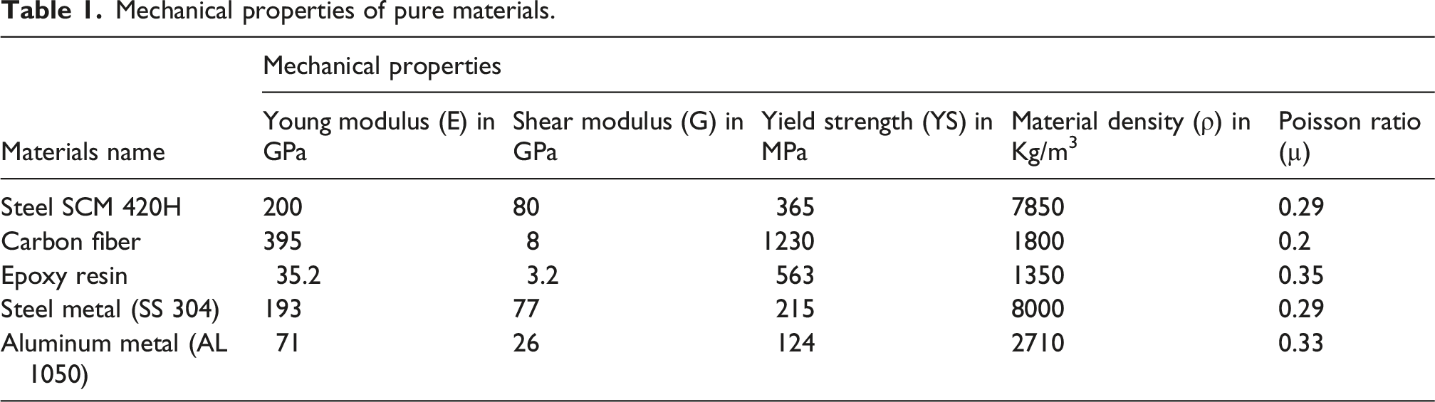
Material Selection: Carbon fiber (Toray T800, E = 395 GPa) and epoxy resin (LY556) were chosen based on their compatibility with metal matrices (SS 304, Al 1050). 15
Taguchi Optimization: An L18 orthogonal array was used to evaluate volume fractions (64–80% CF, 15–21% hybrid layered carbon fiber–epoxy composite with metallic wire reinforcement), with Young’s modulus as the response variable (Figure 2).
The Taguchi design of experiments (DOE) approach was employed in this study to identify relatively optimal material compositions under linear elastic assumptions rather than to predict absolute mechanical properties. Given the anisotropic and layered nature of fiber-reinforced polymer composites, exact prediction of stiffness using statistical methods alone is not feasible. Therefore, Taguchi optimization was used to compare different material combinations on a relative basis and to identify stiffness-maximizing compositions within the defined experimental design space. The optimized compositions were subsequently evaluated through numerical simulations and experimental testing to assess their comparative structural response.
Layer Calculation: Individual layer thicknesses were derived from Equations. 1–5, ensuring <5% deviation from theoretical densities.
Manufacturing: Stacking sequences were fabricated via compression molding (80°C, 10 MPa) and machined using WJM (pressure: 350 MPa, abrasive: garnet #80).
The research methodology, illustrated in Figure 1, follows a systematic workflow for composite spur gear development. Carbon fiber (CF) was selected as the primary reinforcement material due to its superior specific strength (3.46 GPa·cm3/g) compared to conventional gear steels (SCM420H: 0.47 GPa·cm3/g) (Wan and Jun, 2016). To enhance both strength and ductility, a hybrid layered composite approach was implemented using a stacking manufacturing process.
16
Methodology of the flowchart.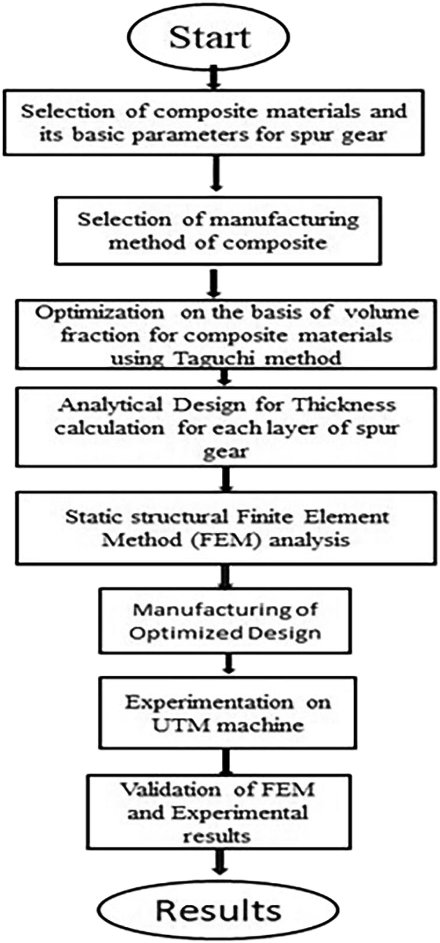
Composite materials, defined as heterogeneous systems comprising two or more distinct phases with markedly different physical/chemical properties. 17 Offer unique advantages for gear applications high specific stiffness (E/ρ ratio up to 200 GPa·m3/kg) Tailorable mechanical properties through controlled: Fiber-matrix interface engineering. 1 Volume fraction optimization and Layup sequence design.
This investigation examines CF and resin matrix in dual reinforcement systems:
Stainless steel (SS304) reinforcement and aluminum (Al1050) reinforcement
The aluminum hybrid layered composite were prioritized given their established aerospace and automotive applications, 18 particularly where: Weight reduction >30% is required, Thermal conductivity >120 W/m·K is beneficial and good corrosion resistance.
Finite element analysis (FEA) was employed for virtual validation, 19 with particular attention to: Stress concentration factors at tooth root fillets, Contact pressure distributions and Thermal-mechanical coupling effects.
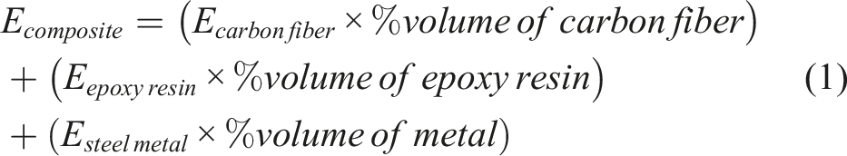
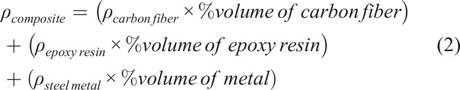
For calculation different mechanical properties following standard formulas were used.
By combination of different volume percentages, statistical data will elaborate the optimized volume percentages of hybrid layered carbon fiber–epoxy composite with metallic wire reinforcement.20–22
The rule-of-mixtures formulations presented above are used only as first-order estimates to approximate the effective elastic modulus and density of the hybrid layered composites. 21 These simplified relations do not capture anisotropic stiffness behavior, interlaminar shear effects, progressive damage mechanisms, or failure behavior inherent to laminated fiber-reinforced composites. Consequently, the calculated properties are not intended to predict strength or failure and are used solely to support preliminary design comparisons prior to numerical and experimental evaluation. 23
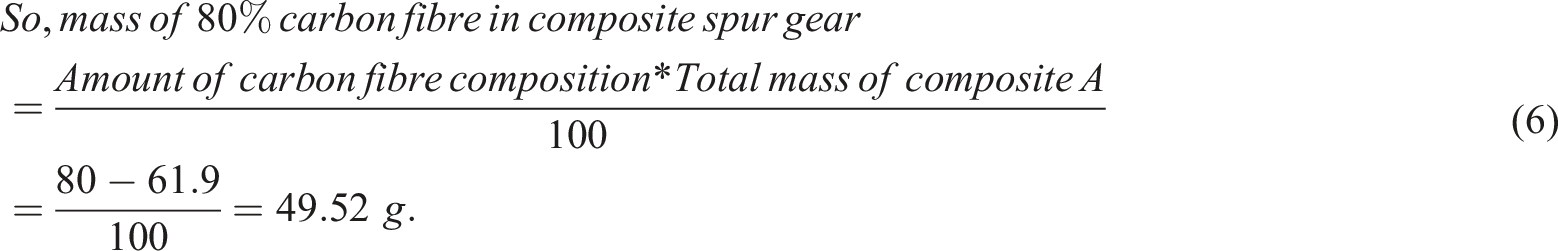
Composite A Carbon Fiber mixed with Epoxy Resin, when the Carbon Fiber (CF) % volume is increased in the composition Youngs modulus is increases as shown in Figure 2(a). So by selecting the optimum design 80% CF and 20% Resin is selected for further manufacturing and testing. (a)Youngs modulus of composite A (b) composite B (c) composite C.22.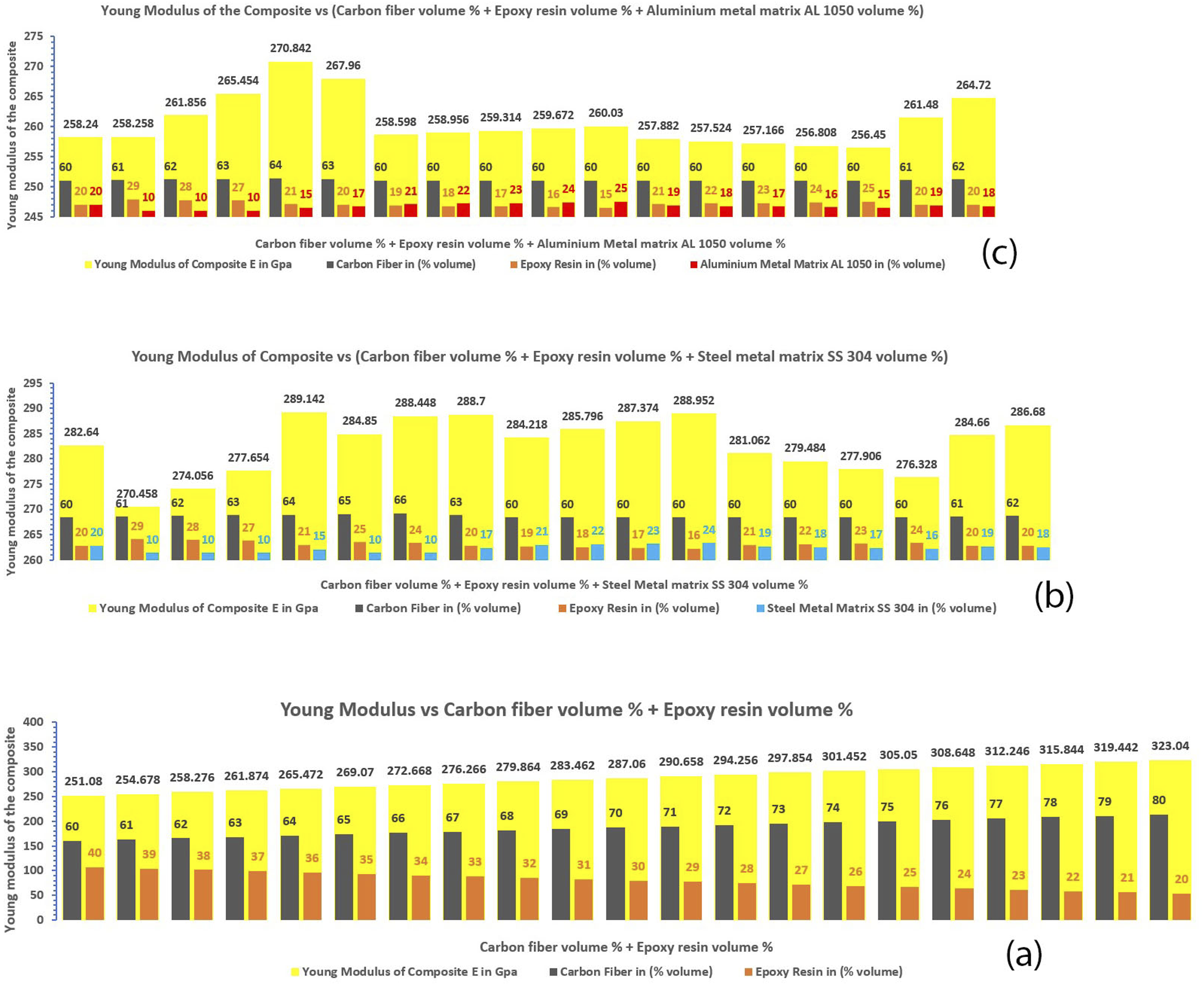
Composite B – Carbon Fiber mixed with Epoxy Resin and SS 316 Meatal Array From this graph Figure 2(b), found the maximum young modulus for composition of 64% Carbon fiber sheet, 21% Epoxy resin and 15% SS 304 hybrid layered carbon fiber–epoxy composite with metallic wire reinforcement to make composite B material.
Mechanical properties of pure materials.
Design and calculation for the thickness of the composite layer
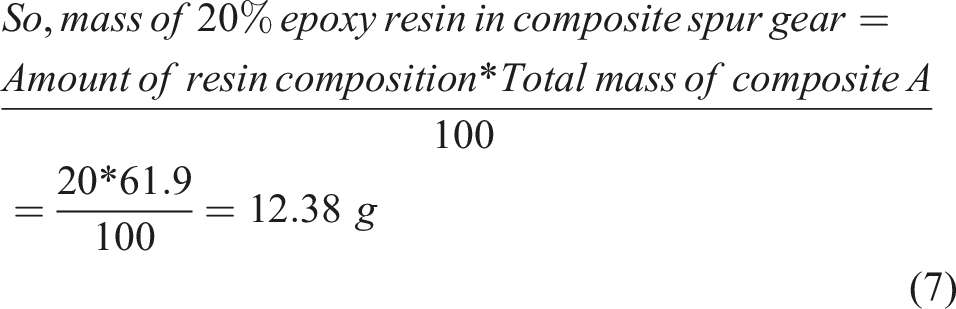
(A) Composite Spur gear made up of 80% Carbon fiber sheet and 20% Epoxy resin
In this case, consider there are total 13 layers in 12.85 mm thickness composite gear having six layers of carbon fiber sheet and seven layers of epoxy resin.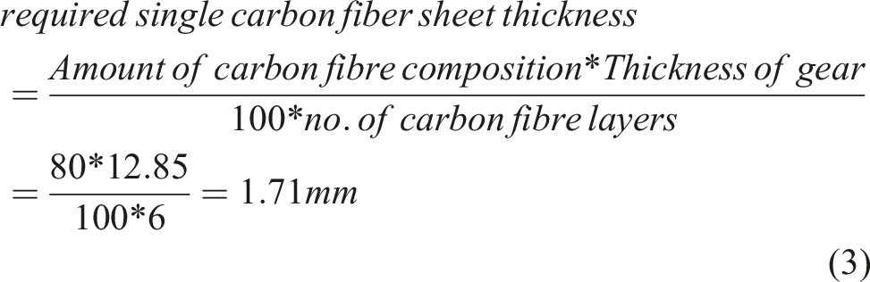
Standard Carbon fiber sheet having thickness of 1.7 mm are available in market.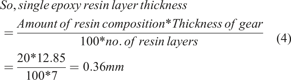
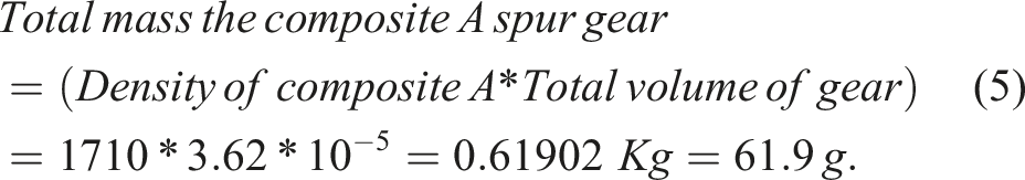
Total Volume of gear = 3.62*10−5m
3
, Density of Composite A = 1710 Kg/m
3
This Table 1 listed mechanical properties of various materials, which are important for assessing their performance in engineering applications:
The details about 80–20% composition of carbon fiber and the epoxy resin Figure 3(a) gives the information about layers of composite, its manufacturing pattern, and thickness of each layer to keep the weight and volume fraction as per the calculation. (B) Composite Spur gear made up of 64% Carbon fiber sheet, 21% Epoxy resin & 15% Steel 304 metal array. Composite A, B, C – Production drawing of spur gear.
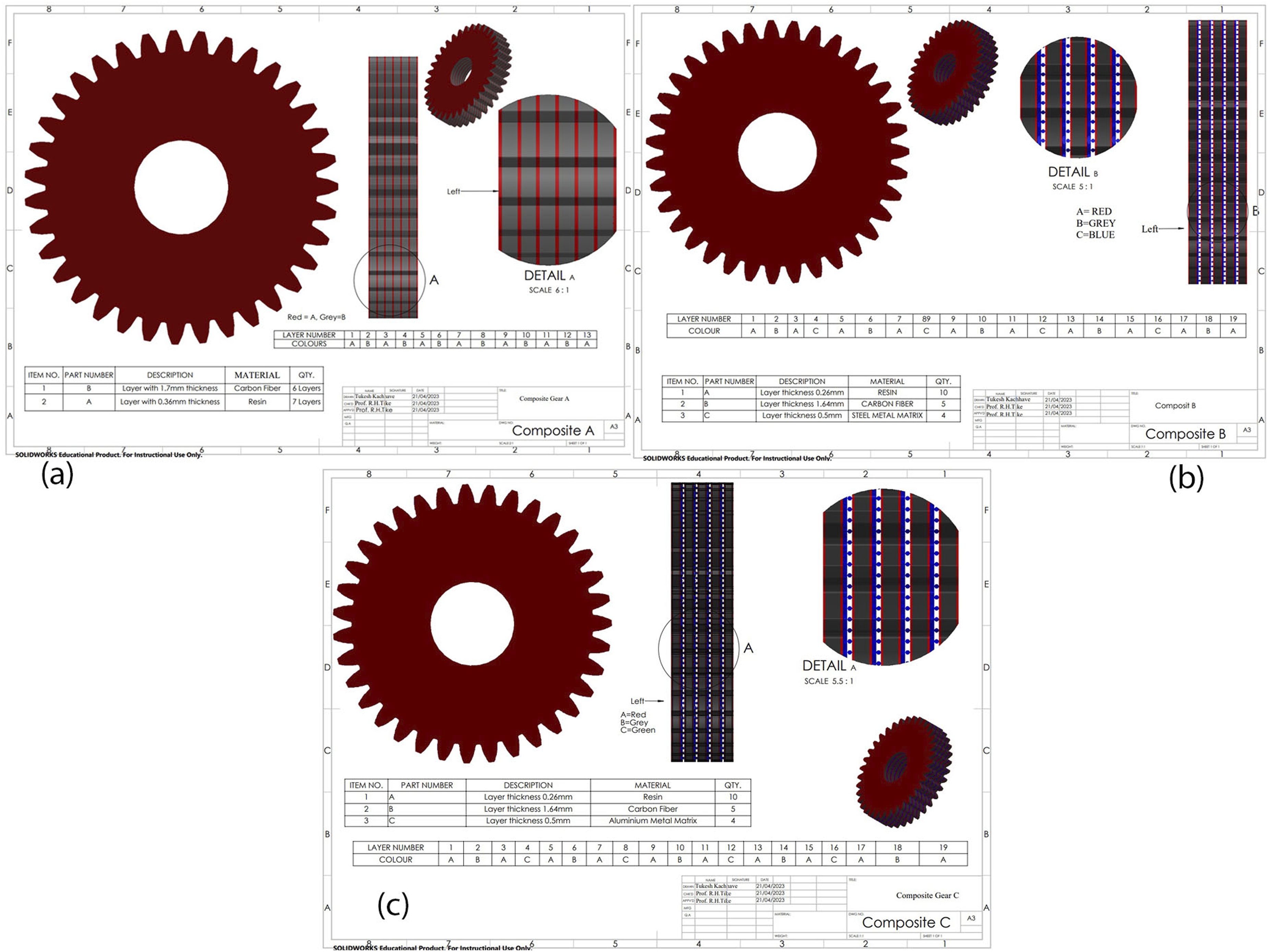
In this case, consider there are total 19 layers in 12.85 mm thickness composite gear having five layers of carbon fibre sheet, 10 layers of epoxy resin & four layers of Steel metal array.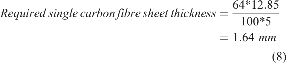
Standard Carbon fibre sheet having thickness of 1.7 mm are available in market.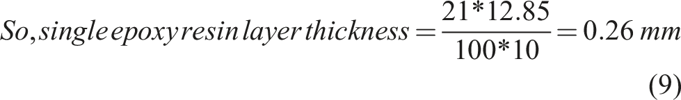
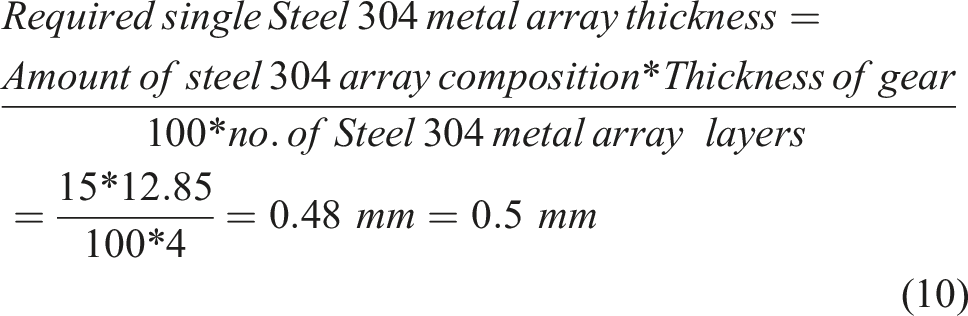
diameter of wire = 0.5 mm
Total Volume of gear = 3.62*10−5m 3 , Density of Composite B = 2635.5 Kg/m 3
Total mass the composite B spur gear = (Density of composite B *Total volume of gear) = 2635.5 * 3.62 * 10−5 = 0.0954 Kg = 95.4 g.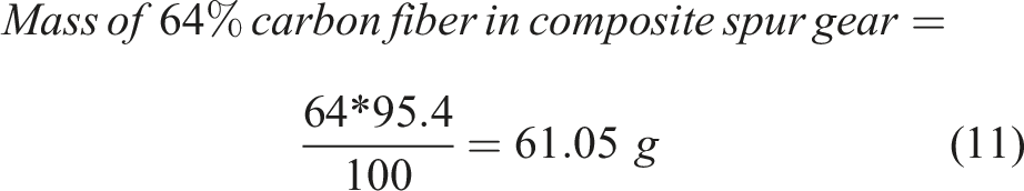
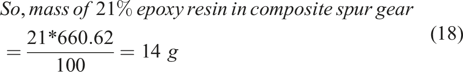
mass of 15% steel 304 metal array in composite spur gear = 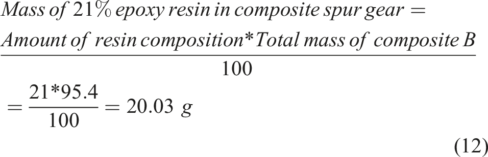
Figure 3(b) shows the details about the thickness of gear and the number of layers, which are used for 64%-21%-15% composition of Carbon Fibre-Epoxy Resin-Steel 304 metal array respectively. As shown in Figure 6 the bill of material of the draft gives a exact information of layer thickness with adequate pattern. In the side view shows the color codes of the layering sequence as red, grey and blue which shows minute details in detailed view. (C) Composite Spur gear made up of 64% Carbon fiber sheet, 21% Epoxy resin & 15% Aluminum 1050 metal array
In this case, consider there are total 19 layers in 12.85 mm thickness composite gear having five layers of carbon fiber sheet, 10 layers of epoxy resin & four layers of Aluminum metal array.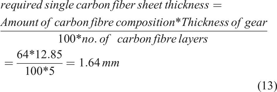
Standard Carbon fiber sheet having thickness of 1.7 mm are available in market.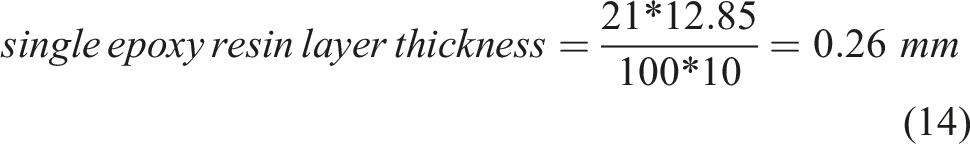

= 0.5 mm diameter wire.
Total Volume of gear = 3.62*10−5m 3 , Density of Composite C = 1840.5 Kg/m 3
Total mass the composite C spur gear = (Density of composite C*Total volume of gear) = 1840.5 * 3.62 * 10−5 = 0.06662 Kg = 66.62 g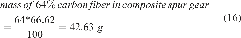

The Figure 3(c) shows the details about the thickness of composite gear and the number of layers, which are used in 64%-21%-15% Carbon Fibre-Epoxy Resin-Aluminum 1050 metal array respectively.
Metal wire reinforcement architecture
The metallic reinforcement used in the hybrid composite gears consists of discrete metallic wire layers embedded within the epoxy matrix. Stainless steel (SS304) and aluminum (Al1050) wires with a nominal diameter of 0.5 mm were employed as reinforcement elements. The wires were arranged in a unidirectional configuration within each metallic layer, with a center-to-center spacing of (1) mm Adjacent metallic layers were oriented orthogonally (0°/90°) to promote improved load distribution and in-plane stiffness. A total of four metallic wire layers were incorporated into the laminate for Composites B and C, positioned symmetrically about the mid-plane of the gear thickness to minimize bending–twisting coupling. The stacking sequence was maintained consistently across specimens to ensure reproducibility. This well-defined wire architecture enables repeatable fabrication and provides a clear mechanical basis for interpreting the numerical and experimental results.
Manufacturing of composite spur gears
The production drawing and design calculations specify different sheet thicknesses, which are prepared accordingly. Composite manufacturing is then carried out using a combination of compression molding and hand layup processes to achieve the desired structure and properties for the composite.
It should be emphasized that the metallic reinforcement used in this study was not introduced in a molten state and does not form a continuous metallic matrix; therefore, the fabricated materials do not constitute conventional metal matrix composites.
Composite A - Carbon fiber mixed with epoxy resin
As shown in Figure 4(a)–(d) to manufacture the composite A spur gear, computed amount of resin and hardener is mixed together and then applied layer on the carbon fibre sheets as per Production drawing and after compression the composite sets then by using water jet machining process desired gear is manufactured. (a) 1.6 mm Thickness of CF sheet (b) resin and hardener (c) WJM used to cut spur gear teeth (d) Composite A spur gear.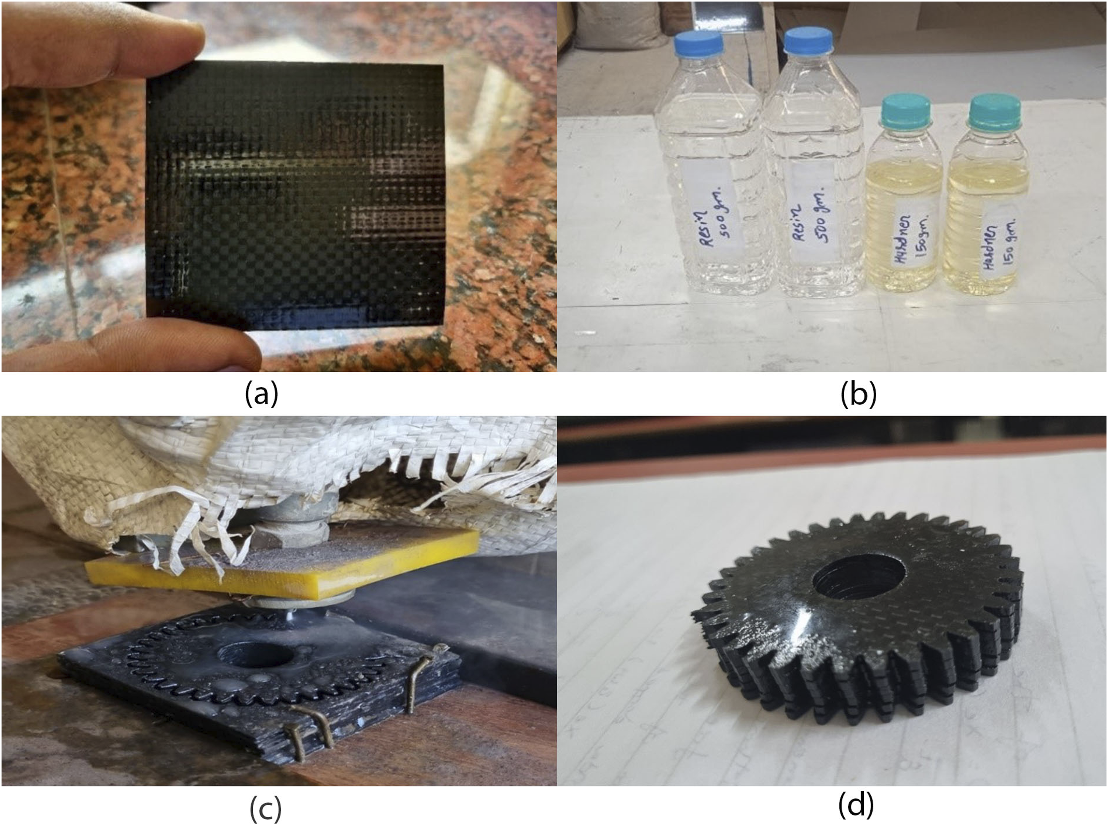
Composite B -carbon fiber mixed with epoxy resin and steel metal array
The Figure 5 shows different stages and components involved in the composite manufacturing process for spur gears. The thickness of a composite sheet is 1.60 mm, indicating that this sheet is one of the layers prepared for the manufacturing process. The sub-image depicts thin composite layer is shown as 0.5 mm. (a) Measurement of composite sheet thickness (b) measurement of thin, (c) metal array layering (d) Composite B spur gear.
The Composite layup structure made from fibers which are interwoven in a crisscross pattern. The fiber orientation and stacking sequence influence the overall stiffness, strength, and other mechanical properties of the composite gear. After the manufacturing process. Composite Layer (c) Composite Layup Structure (d) Final Manufactured Composite B Spur Gear, the gear’s structure, surface finish, and tooth profile indicate a successful molding process, making it ready for experimental testing and performance evaluation.
Composite C - Carbon fiber mixed with epoxy resin and aluminum metal array
The aluminum hybrid layered carbon fiber–epoxy composite with metallic wire reinforcement prepared for use in Composite C this layer likely consists of a combination of aluminum metal wire reinforcement layers embedded within epoxy matrix elements to provide the necessary strength, stiffness. It forms one of the primary structural layers in the composite, contributing to the overall mechanical performance. Water Jet Machining (WJM) to precisely cut the spur gear teeth. The final fully manufactured Composite C spur gear. The gear has been shaped and finished, and the tooth profile appears well-defined, indicating successful cutting using WJM. This gear is now ready for performance evaluation and testing to validate its mechanical properties.
Mechanical testing protocol
Compressive Strength: ASTM D695, crosshead speed: 1.3 mm/min (Figure 9).
Microstructural analysis: SEM (JEOL JSM-IT800) to examine fiber-reinforcement bonding post-failure.
Uncertainty Quantification: five repeated tests per composite, errors <±3.2% (95% CI).
Result and discussion
Boundary conditions and loading definition
The finite element simulations were performed under static loading conditions to compare the relative structural response of different gear materials. A tangential load of 87.47 N was applied at the pitch circle of a single gear tooth to represent a simplified tooth loading condition. The load was applied normal to the tooth flank surface. The gear hub was constrained with fixed boundary conditions to represent shaft attachment, while the remaining degrees of freedom were left unconstrained. Contact interactions between mating gear teeth were not modeled, and frictional effects were neglected to isolate material-level deformation behavior. A uniform mesh size of 1 mm was used across all simulations to ensure consistency in numerical comparison.
Finite element analysis of ideal & composite gear
Finite Element Analysis specification of an ideal steel gear featuring 35 teeth and their diameter 65 mm. In FEA maximum total deformation under load is generated as 0.00,036,678 mm when subjected to a loading condition of 87.47 N. The boundary condition specifies that the load is applied to a single tooth, and the mesh size used for the simulation is 1 mm. This minimal deformation indicates the gear’s rigidity and ability to withstand applied forces without significant structural changes. The maximum generated Equivalent Stress is 8.6621 MPa, while the minimum generated Equivalent Stress is 1.4515 × 10⁻⁵ MPa under the same loading condition of 87.47 N. The factor of safety for the standard spur gear, which is determined to be 15. A factor of safety of 15 indicates a high level of reliability, suggesting that the gear can safely withstand the applied loads without failure. This metric is crucial for ensuring the gear’s durability and longevity in practical applications, particularly in high-stress environments like automotive gearboxes. The numerical results are interpreted in terms of relative stiffness and deformation trends rather than failure criteria, due to the anisotropic nature of the composite materials.
FEA analysis of Composite A
The Figure 6 presents a detailed analysis of Composite A spur gear, composed of 80% carbon fiber sheet and 20% epoxy resin, the total deformation analysis for Composite A spur gear The results indicate a maximum generated total deformation of 0.00,022,652 mm, with a minimum generated total deformation of 0 mm when subjected to a loading force of 87.47 N in Figure 6(a). In Figure 6(b) shown maximum principal Stress of 9.1178 MPa and a minimum generated principal Stress of 8.8198 × 10⁻⁶ MPa at the same loading force of 87.47 N and factor of safety for the Composite A spur gear, which is determined to be 15. (a) Total deformation of Composite A (b) equivalent stress of Composite A (c) factor of safety of Composite A.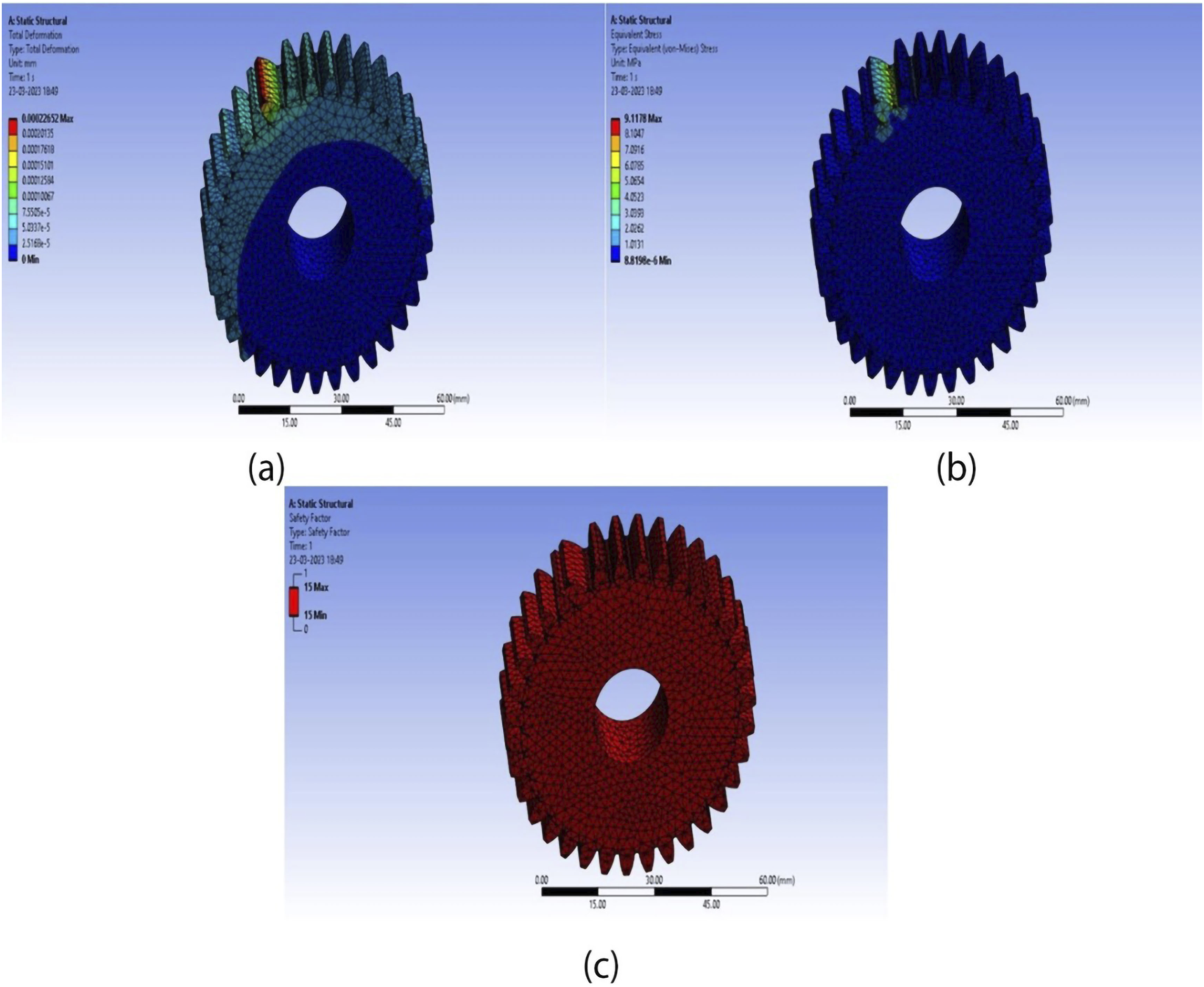
The reduced deformation in Composite A is attributed to the high specific modulus of carbon fiber, which provides superior stiffness at lower density. Additionally, the anisotropic nature of fiber reinforcement restricts deformation along the principal load direction, while the layered structure helps distribute stresses efficiently across the laminate.
FEA analysis of Composite B
In the Figure 7 detailed analysis of Composite A spur gear, composed of 80% carbon fiber sheet and 20% epoxy resin, total deformation of 0.00,022,652 mm, when subjected to a loading force of 87.47 N in Figure 7(a). (a) Total deformation of Composite B (b) equivalent stress of Composite B (c) factor of safety of Composite B.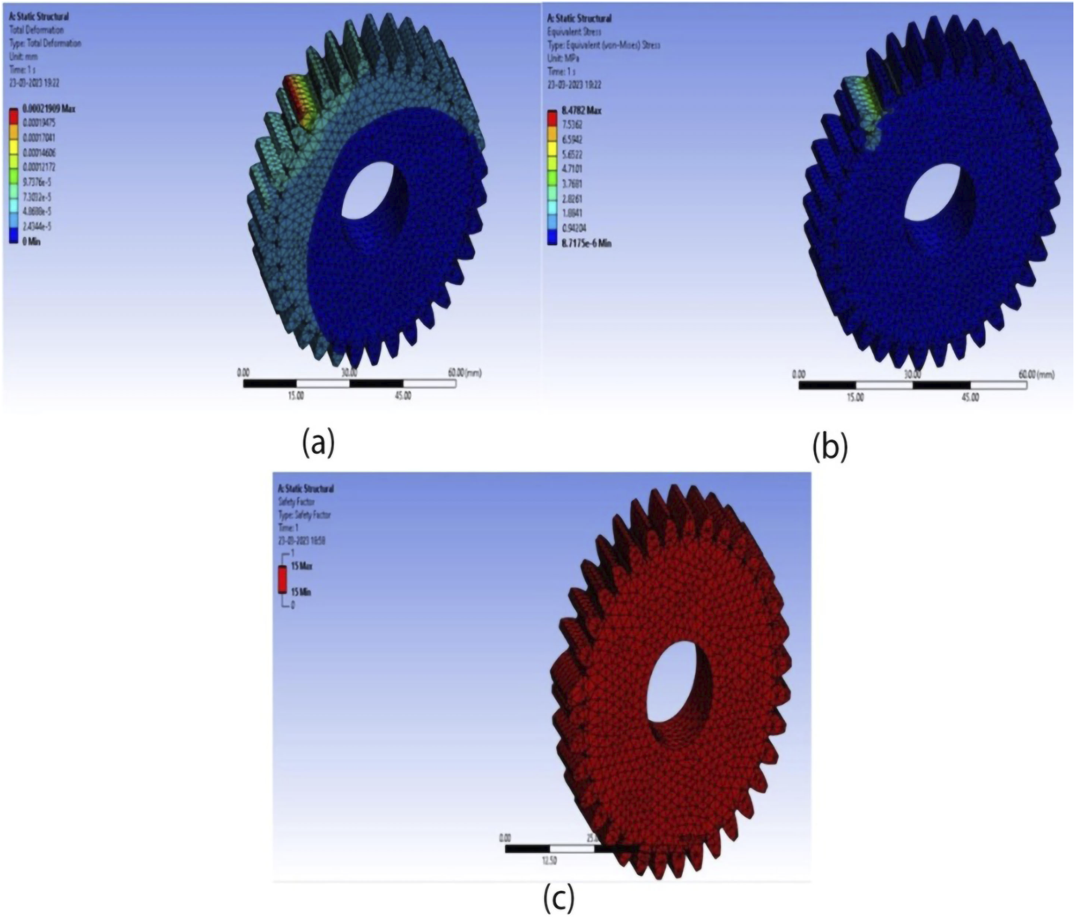
Equivalent Stress of 9.1178 MPa and a minimum generated Equivalent/principal Stress of 8.8198 × 10⁻⁶ MPa at the same loading force of 87.47 N in Figure 7(b). The stress values indicate the distribution of stress throughout the gear, highlighting areas of high stress concentration that are critical for assessing potential failure points. Factor of safety for the Composite A spur gear, which is determined to be 15 Figure 7(c).
The superior performance of Composite B is attributed not only to the higher modulus of stainless steel but also to the orthogonal wire arrangement (0°/90°), which facilitates multidirectional stress transfer. The steel wires act as load-bearing bridges at the tooth root, redistributing bending stresses and reducing localized stress concentration. Additionally, improved interfacial bonding between steel and epoxy enhances load transfer efficiency, resulting in higher compressive strength.
FEA analysis of Composite C
The analysis reveals a maximum generated Equivalent Stress of 3.1137 × 10⁻⁷ MPa and a minimum generated Equivalent Stress of 0 MPa when subjected to a loading force of 87.47 N.
Equivalent stress of Composite C spur gear
The analysis reveals a maximum generated Equivalent Stress of 3.1137 × 10⁻⁷ MPa and a minimum generated Equivalent Stress of 0 MPa when subjected to a loading force of 87.47 N in Figure 8(a). The boundary condition specifies that the load is applied to a single tooth, and the mesh size used for the simulation is 1 mm. The extremely low maximum equivalent stress indicates that Composite C exhibits excellent load-bearing capacity under the specified conditions, suggesting it can effectively manage the applied force without significant stress accumulation. (a)Total deformation of Composite C (b) equivalent stress of Composite C (c) factor of safety of composite.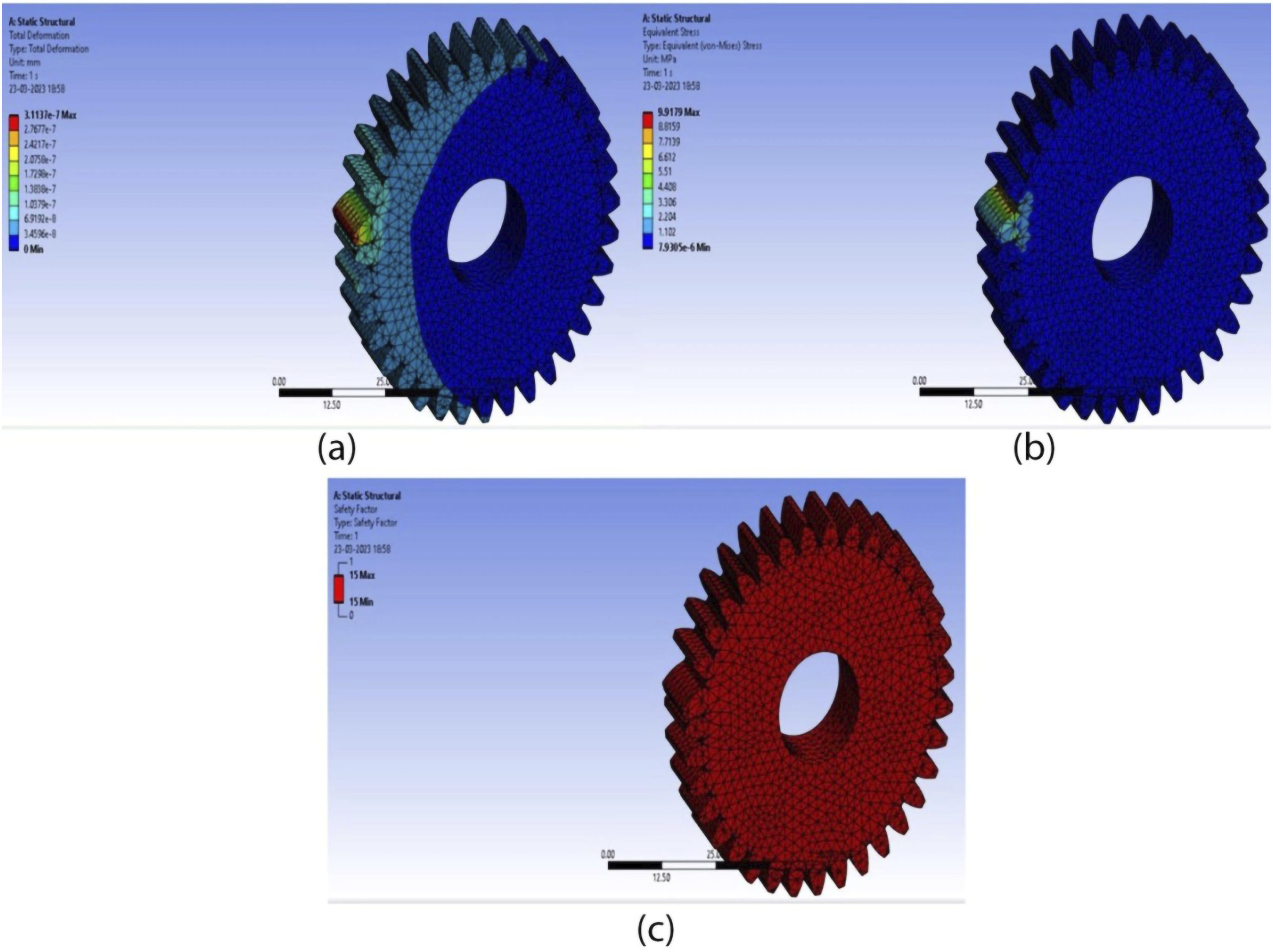
The reduced performance of Composite C can be attributed to poor interfacial adhesion between aluminum and epoxy, resulting from inadequate wettability and weak bonding. Furthermore, the relatively low modulus of aluminum limits its ability to effectively reinforce the composite, thereby reducing its overall load-bearing capacity.
Equivalent stress of another configuration
The findings show a maximum generated Equivalent Stress of 9.9179 MPa and a minimum generated Equivalent Stress of 7.9305 × 10⁻⁶ MPa at the same loading force of 87.47 N Figure 8(b). The boundary conditions remain consistent, with loading applied to a single tooth and a mesh size of 1 mm. This higher stress value indicates a different performance characteristic under load, highlighting the importance of understanding how various configuration can impact the gear’s performance.
Factor of safety for Composite C spur gear
This sub-image shows the factor of safety for the Composite C spur gear, which is determined to be 15 Figure 8(c). A factor of safety of 15 suggests a robust safety margin, indicating that the gear can reliably handle the applied loads without risk of failure. This high factor of safety is crucial for ensuring the durability and reliability of Composite C spur gear in applications that require high performance and safety.
Failure modes of various composites.
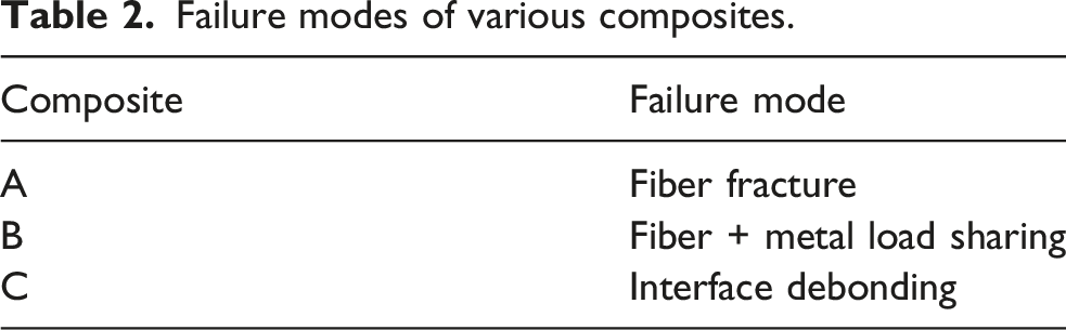
Although all composites shows a similar factor of safety (∼15), their failure mechanisms is different significantly. Composite A is primarily governed by fiber fracture, Composite B shows synergistic load sharing between fiber and metal reinforcement, while Composite C is more sensitive to interfacial debonding due to weak bonding between aluminum and matrix.
Experimental testing and validation
Experimental results will provide a more realistic measure of the composite’s mechanical properties under compressive loads. The significant differences in compressive strength between the three composites suggest that adding a reinforcement material (steel or aluminum) changes the failure mode and enhances load distribution. For testing the ultimate compressive load on the different types of composites specimens UTM compressive loading 30-ton machine is used the results are as follows.
The compressive behavior of the fabricated composites was evaluated using a Universal Testing Machine (UTM) under controlled loading conditions. Figure 9(a) illustrates the test setup, where the flat specimens were subjected to compressive loading with proper fixture alignment. For Composite A, having a cross-sectional area of 390 mm2 and gauge length variation from 600 mm to 632 mm, the ultimate load attained was 12.90 kN, corresponding to an ultimate compressive strength (UCS) of 33.08 N/mm2, with maximum displacement recorded at 10.40 mm before failure, and a breaking load of 12.75 kN. Composite B, tested under identical dimensional conditions, exhibited superior performance with an ultimate load of 24.3 kN and a calculated strength of 62.31 N/mm2, with a percentage elongation of 5.33%; however, the reported value of Young’s modulus was zero, likely due to a data acquisition or calculation error under compressive mode. Composite C, prepared with slightly varied gauge dimensions (590–600 mm), demonstrated an ultimate load of 19.60 kN, yielding a UCS of 50.30 N/mm2, with maximum displacement limited to 6.95 mm, while the breaking load and stress were 16.58 kN and 4.05 N/mm2, respectively. (a) UTM test setup (b) Composite A test result (c) Composite B test result (d) Composite C test result.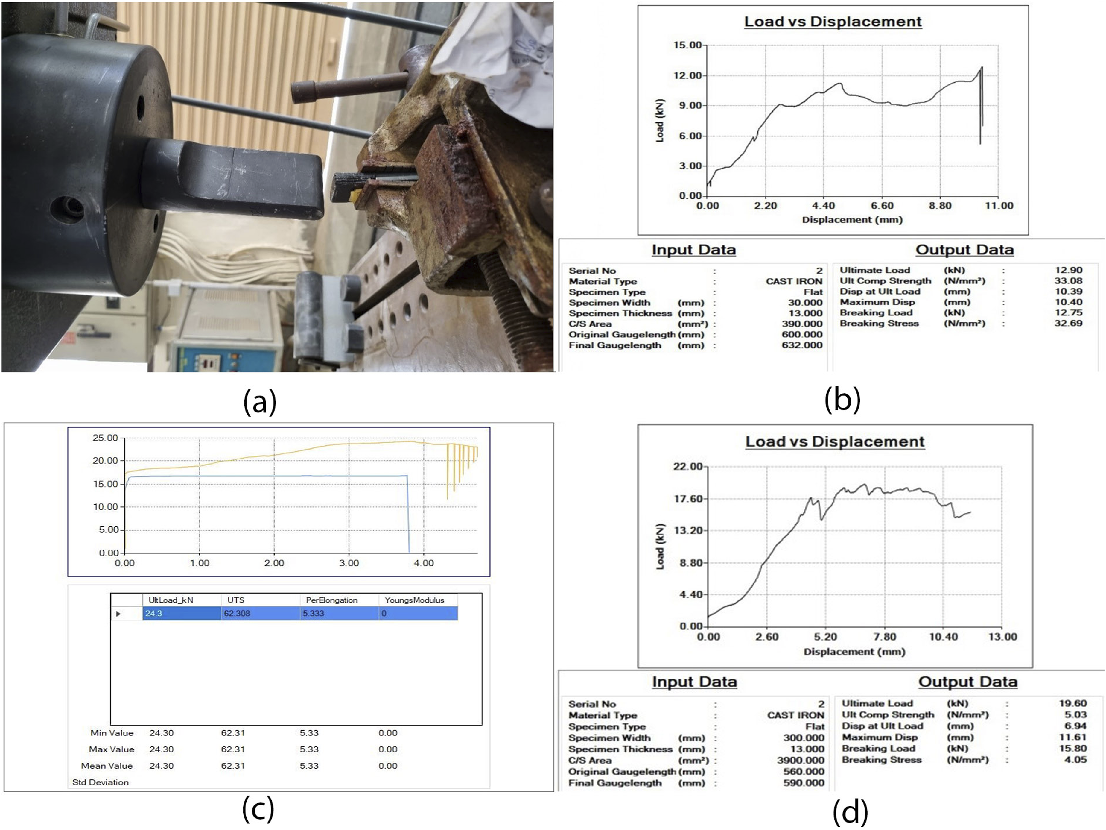
The load–displacement curves of all composites indicated a near-linear load progression up to the peak load, followed by a sudden drop, signifying brittle fracture characteristics. These findings emphasize the distinct compressive responses of the tested composites, highlighting significant differences in their load-bearing capability, deformation resistance, and failure modes, which are critical for their prospective structural and automotive gear applications.
Comparative static response metrics.
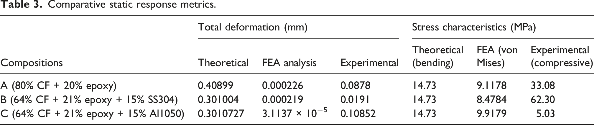
Composite B (64% carbon fiber, 21% resin, 15% steel) achieved the highest experimental strength (62.30 MPa), far exceeding theoretical (14.73 MPa) and analytical (8.47 MPa) values due to the reinforcing effect of the steel reinforcement. In contrast, Composite C (64% carbon fiber, 21% resin, 15% aluminum) showed the lowest experimental strength (5.03 MPa), much lower than predicted, reflecting insufficient reinforcement from the aluminum array. The differences highlight limitations of theoretical/analytical models and the necessity of experimental validation for accurate performance assessment.
The compression tests conducted in this study were intended solely to compare the bulk load-bearing behavior of the fabricated composite materials and do not represent gear-specific failure modes such as tooth root bending fatigue, contact fatigue (pitting), wear, or dynamic operating conditions.
Differences observed between theoretical estimates, numerical predictions, and experimental results can be attributed to the simplified assumptions adopted in the analytical and numerical models. The linear elastic material representation, idealized boundary conditions, and neglect of interlaminar damage mechanisms contribute to deviations from experimentally measured behavior. These discrepancies highlight the limitations of simplified modeling approaches for layered composite systems and emphasize the necessity of experimental validation when evaluating hybrid composite structures.
Conclusion
This study demonstrates the feasibility of using hybrid layered carbon fiber–epoxy composites with metallic wire reinforcement for lightweight spur gear applications. Static finite element analysis and compression testing indicate improved stiffness-to-weight characteristics compared to conventional steel gears. The results confirm that the incorporation of metallic wire layers enhances load distribution within the laminate, particularly for steel-reinforced configurations. Findings include:
FEA Validation: Composite A (80% CF + 20% epoxy) and Composite C (CF + Al array) showed 3× lower stress than steel gears under static loads.
Experimental Results: UTM tests confirmed Composite B’s (CF + steel array) exceptional compressive strength (62.3 MPa).
Weight Reduction: The composite gears reduced overall weight by 38–42%, lowering gearbox mass by 18–20%.
These results validate hybrid layered composite as a transformative solution for automotive gears, combining lightweight design. While the findings are limited to static structural behavior, they provide a foundation for further investigation into gear-specific fatigue, wear, and dynamic performance in future work.
Footnotes
Acknowledgements
The authors gratefully acknowledge. We extend our appreciation to JJT University, Jaipur, for providing essential laboratory facilities and computational resources that enabled this work.
Funding
The authors received no financial support for the research, authorship, and/or publication of this article.
Declaration of conflicting interests
The authors declared no potential conflicts of interest with respect to the research, authorship, and/or publication of this article.
Data Availability Statement
The data supporting the findings of this study are available from the corresponding author upon reasonable request.