
Abstract
This research assesses the mechanical and electromagnetic interference (EMI) shielding performance of cellulose-interlayered glass/carbon hybrid fiber-reinforced polymer (HFRP) composites at room temperature (RT) and cryogenic (−196°C) conditions. Symmetric [GC]2[CG]2 and [CG]2[GC]2 arrangements were constructed. Mechanical testing demonstrated that augmenting the density of the cellulose interfaces markedly enhanced flexural performance, while concurrently resulting in a drop of tensile strength by as much as 23% owing to the development of weaker interlayers. Bending tests revealed that all-plane interleaving enhanced strength from 215 to 250 MPa for G/C and from 226 to 335 MPa for C/G; in cryogenic conditions, the flexural strength of C/G reached a maximum of 340 MPa. Additionally, all composite variations exceeded the 30 dB commercial reference value for EMI shielding effectiveness, while the cryogenically processed all-plane C/G laminate reached a SETot peak of 63 dB. The protective mechanism was mostly absorption-based (∼80%), augmented by the porosity configuration of the cellulose fibers and cryogenically produced micropores that facilitate repeated internal reflections. The results confirm the multifunctional efficacy of sustainable cellulose interlayers for high-performance applications under harsh conditions.
Introduction
Fiber-reinforced polymer (FRP) composites are widely used in aerospace, marine, and sports industries, as well as in cryogenic fuel tanks, hydrogen storage systems, pressure vessels, and superconducting devices. 1 Recently, carbon fiber-reinforced polymer (CFRP) and glass fiber-reinforced polymer (GFRP) composites, along with their hybrid combinations, have been increasingly utilized to reinforce structural elements in various forms such as plates, strips, gratings, and bars. 2 The growing popularity of these composites is primarily due to their high efficiency. In the context of green energy, the design of larger wind turbine blades has become a strategic priority for manufacturers.3,4 Glass fiber/carbon fiber hybrid composites have garnered attention for offering a balanced compromise between cost and mechanical performance. 5 As a result, the aerospace industry, automotive manufacturing, wind turbine blades, and other industrial sectors extensively employ HFRP composites. 6
The hybrid effects and failure mechanisms of HFRP under various loading situations are complicated and ambiguous due to the hybrid parameters. In order to tackle these issues, a significant amount of research has concentrated on the way HFRP affects its mechanical properties and fracture mechanisms. 7 Intra-laminar hybridization7,8 and inter-laminar hybridization 9 are two of the main hybrid approaches that are commonly researched. Interlaminar hybridizations are prevalent because of their beneficial features and low cost of manufacture. Pandya et al. 10 conducted an experimental study on the in-plane tensile and compressive properties of two types of HFRP composites fabricated using epoxy resin with carbon fabrics and E-glass fabrics. Researchers found that the tensile strength was 436 MPa when the glass fabric layers were placed on the outside and the carbon fabric layers on the inside, while the value was 421 MPa when the carbon fabric layers were positioned outside and the glass fabric layers within. In the same context, Jagannatha et al. 11 prepared carbon/glass hybrid composites and investigated their mechanical properties, such as tensile strength and tensile modulus. Based on their findings, they determined that tensile strength increases with an increase in the amount of carbon fiber fabric. Subagia et al. 12 analyzed the effect of stacking sequences of carbon/basalt on the flexural properties of HFRP. They reported that flexural characteristics are significantly impacted by the HFRP stacking sequence. With the carbon fiber on the compression side, the HFRP composite showed improved flexural characteristics. This indicates that, in HFRP composites as well, the stacking sequence and the layer count of carbon or glass fibers affect the tensile and flexural properties.
Applications for cryogenic tanks encompass the storage of liquid hydrogen, liquefied natural gas (LNG), and liquid oxygen. Given the rising demand for these tanks, it’s critical to identify and prevent damage, such as fractures, to stop leakage. 1 The major problem in the application of HFRP composites in the cryogenic regime is due to the development of residual stress. Especially when using carbon fibers with a coefficient of thermal expansion close to zero, thermally induced stresses can occur between the fibers and the matrix at the microstructural level. 13 Severe changes can occur, particularly when they are periodically exposed to cryogenic temperatures. 14 Delamination and microcracking are some of the most frequent damage phenomena that can develop in composite materials exposed to cryogenic temperatures.15–17 Some literature sources have shown that the tensile and flexural strengths of composites increase as ambient temperature decreases.18,19 In the study by Meng et al., 18 bending and tensile tests were performed on CFRP composites. The integration of cryogenic conditioning resulted in a roughly 50% enhancement of the flexural characteristics, thereby altering the resultant damage. This phenomenon is related to variations in the mechanical characteristics of the polymer matrix and alterations in damage formation in composites when the temperature varies. When the material is abruptly exposed to cryogenic temperatures, thermal shocks can result in microcracks in the reinforcement phase, the matrix phase, or at the interface in composites.20,21 Recognizing this issue, researchers have conducted studies aimed at improving interface properties through interlaminar reinforcement in order to expand the scope of applications. 19 The interleaving method is an effective toughening technique that can achieve high interlaminar toughness while maintaining the original in-plane properties of composites.22,23 Yasaee et al. 23 studied the interlaminar toughening effects of various types of interlayers, such as polyimide film and chopped aramid fiber film. It was shown that interlayers can effectively suppress delamination crack propagation. In our previous study, 24 the interface properties of the composite structure were improved by inserting microfiber veils between the layers. The flexural strength increased by 1–8% thanks to the various microfiber veils.
Paper has been crucial throughout human history and is still very essential in today’s economy. By combining cellulose fibers with fillers, paper can have conductive, magnetic, photoluminescent, catalytic, antimicrobial, acoustic damping or flame retardant properties. 25 High-performance flexible cellulose paper has been extensively and thoroughly studied for its potential applications in electrical smart devices, 26 flexible energy storage devices, 27 electromagnetic shielding, 28 and anti-static. 29 Interleave materials are usually incorporated as a single layer in a laminated composite, and while they can play a significant role in toughening mechanisms, they can also be added periodically. This approach increases damage tolerance and controls the direction and distribution of major damage propagation. 30 Damage due to a mismatch in elastic properties and coefficient of thermal expansion between laminates can be minimized. 31 In our previous study, 32 we found that cellulose paper used as an interlayer in fiber-metal laminated composites significantly influenced the fracture behavior at that interlayer. Cellulose fibers enhanced damage tolerance by demonstrating methods such as fracture orientation, fiber bridging, and crack arrest. Zhu et al. 33 incorporated cellulose nanofiber films between the layers of carbon-fiber laminated composites and investigated the interlaminar properties of this material. While the cellulose nanofiber films increased interlaminar toughness, the tensile and flexural properties decreased. According to the results, tensile strength decreased by approximately 9% and flexural strength by 7% compared to unreinforced composites.
The rapid proliferation of communication infrastructures such as 5G, alongside the increasing density of electronic devices and satellite systems, has led to a continuous rise in electromagnetic radiation (EMR) exposure.34,35 It is well-documented that elevated EMR levels exert adverse effects on both biological organisms and the operational integrity of electronic devices.36,37 Electromagnetic interference (EMI) shielding is the critical process of attenuating free electromagnetic radiation through absorption or reflection to mitigate these detrimental effects. While high-conductivity metallic materials are traditionally employed for EMI shielding, their application is often constrained by a reflection-dominant shielding mechanism, high density, susceptibility to corrosion, and processing complexities.38,39 Consequently, conductive fiber or particle-reinforced polymer composites—particularly those based on carbon fiber—are increasingly preferred due to their superior specific strength, chemical resistance, and enhanced EM absorption capabilities.35,40 However, inherent vulnerabilities such as delamination and microcracking have intensified research into reinforcing interlaminar bonding within these materials.16,22,23 For specialized applications including stealth aircraft, UAVs, and satellite systems, evaluating the EMI shielding performance of interleaf structures—particularly under extreme thermal conditions—is essential to expand their operational potential. Literature regarding composites integrated with interleaf structures and subjected to cryogenic conditions indicates that these modifications effectively impede crack initiation and propagation caused by thermal expansion mismatches, 41 while simultaneously preserving the shielding integrity of the material.42,43
Although the use of cellulose fibers as an interfacial layer in fiber-reinforced composites is not common, the interfacial effectiveness of non-woven natural fibers is an attractive field of study. This study focuses on the use of cellulose fibers as an interfacial layer in HFRP composites, with the aim of improving damage tolerance at different temperatures. In this regard, this study demonstrates that cellulose interlayer integration within glass/carbon and carbon/glass HFRP composites significantly influences their mechanical and electromagnetic behaviors under both room and cryogenic conditions. While tensile strength exhibited a trade-off with increased interfacial layering, enhancements in flexural strength, and electromagnetic shielding effectiveness, especially in C/G stacking sequences, underscore the multifunctional benefits of cellulose interleaving. The findings affirm that cellulose-based interlayers not only offer sustainable reinforcement strategies but also enable tailored performance for advanced structural applications in cryogenic and EMI-sensitive environments. These insights open avenues for the rational design of next-generation hybrid composites with optimized mechanical resilience and functional capabilities.
Materials and methods
Materials
HFRP composite materials were produced using 200 tex glass and carbon fiber woven fabrics (Dost Kimya, Türkiye). The diameters of the fibers are 7 and 9 µm, respectively. A4-sized cellulose sheets (80 g/m2 and 0.10 mm, Ve-Ge, Türkiye), used without any modification, are utilized as the interlayer in the HFRP composite. The MGS L285 epoxy system, suitable for vacuum bagging and hand lay-up methods, was purchased from Hexion, Germany. The manufacturer specifies a hardener-to-epoxy mixture ratio of 40% by weight.
Characterization
Fourier transform infrared spectroscopy (FTIR) analysis was conducted in the 4000-500 cm−1 range utilizing a Nicolet-iS20 spectrometer to assess the cellulose fibers. Scanning electron microscopy (SEM) observations were performed using a Hitachi-SU1510 to examine the cellulose fiber structure.
Fabrication of HFRP composites
Variations in stacking sequences offer design flexibility to enhance the performance of composite structures.
5
Moreover, symmetric stacking sequences (orthotropic) demonstrate a greater hybrid effect. In structures subjected to dynamic loads, such as wind turbines, a symmetric stacking sequence is preferable.5,44 Concerning this matter, Figure 1 illustrates six distinct hybrid composite stacking sequences, each composed of eight symmetrical layers. In the configuration of Neat G/C reference sample, the stacking sequence [GC]2[CG]2 begins with glass fiber fabric on the outermost layers, followed by alternating layers of carbon and glass fibers. Cellulose paper was incorporated either at the mid-plane or between all-planes (Figure 1(a)). Similarly, Figure 1(b) illustrates the [CG]2[GC]2 configuration, where carbon fiber fabric forms the outermost layers, followed by alternating glass and carbon fiber layers. As with the previous configuration, cellulose paper was inserted at the mid-plane and between each plane. Schematic representation of the stacking sequence of the HFRP composites fabricated: (a) [GC]2[CG]2 configuration and (b)[CG]2[GC]2 configuration.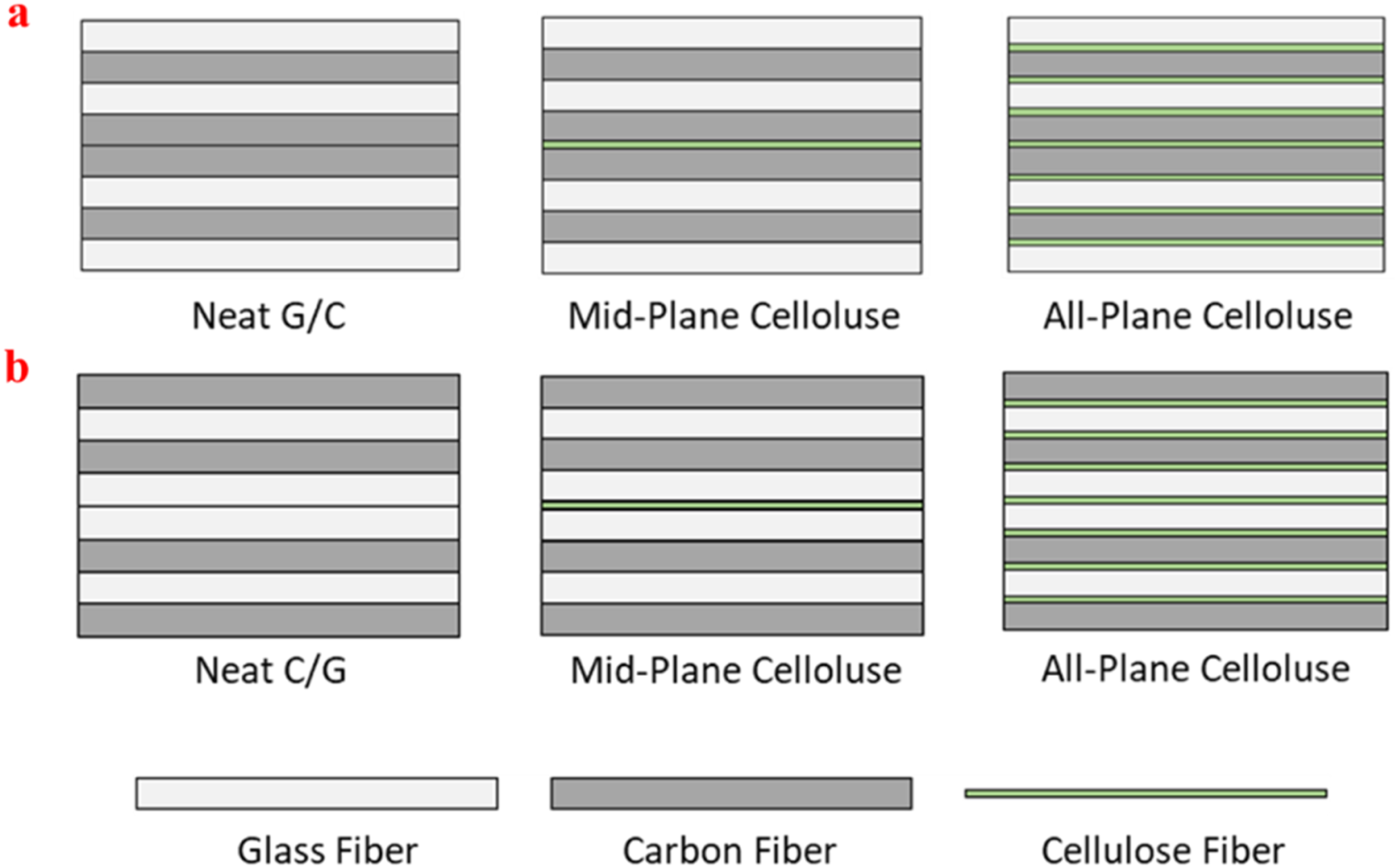
The fabrication of HFRP composites was carried out in two stages (Figure 2) as described in detail in our previous study.5,32 Cellulose sheets and woven fabrics for HFRP composite fabrication were cut to dimensions of 200 × 250 mm and then adjusted to test sample standards post-production. In the first stage, the cellulose sheets, placed either at the middle plane or between all reinforcement planes, were successfully impregnated with the epoxy polymer using the hand lay-up method, and epoxy resin was applied to each layer with a brush to ensure uniform wetting. The layers were then stacked sequentially, maintaining consistent impregnation throughout. In the second stage, vacuum bagging was employed to remove excess epoxy and eliminate air pockets. The composites were subsequently cured at 80°C for 4 h under a vacuum pressure of 0.8 bar. Three various HFRP composites were generated as a consequence of the fabrication process: Neat HFRP composite (2 mm thickness), Mid-plane paper-reinforced (2.1 mm thickness), and All-plane paper-reinforced (2.5 mm thickness). Fabrication stages of HFRP composite materials.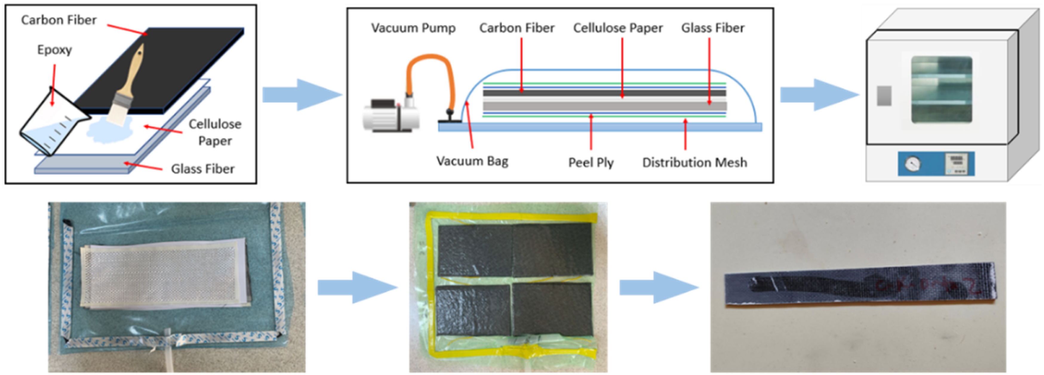
Mechanical tests
Tensile and three-point bending tests were performed to characterize the mechanical properties of HFRP composites. All tests were performed on an Instron 8801 universal testing machine with a crosshead speed of 2 mm/min (Figure 3). Image during (a) the tensile and (b) the three-point bending test.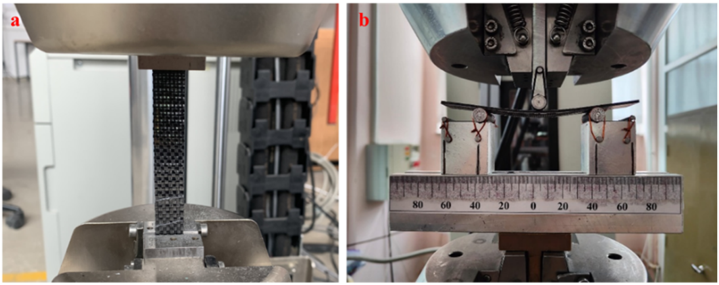
Specimens for tensile tests were prepared in accordance with ASTM D3039.
45
Three-point bending followed ASTM D7264 with a thickness-to-span ratio of 1:16.
46
For these tests, at least five repetitions of each HFRP composite were obtained (Figure 4). Specimens exposed to cryogenic conditions for (a) tensile and (b) three-point bending tests.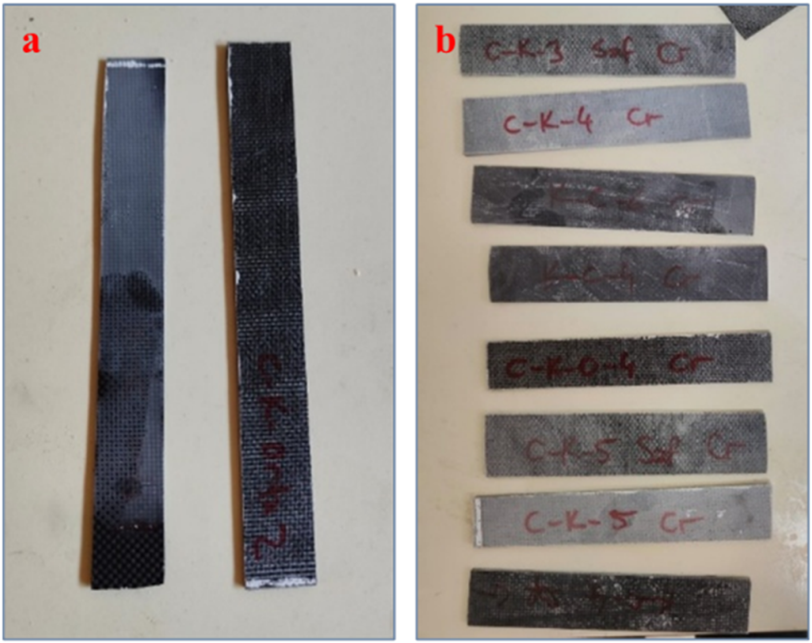
To assess the performance of HFRP composites under prospective operation conditions, two conditioning scenarios were established: room temperature (RT) and cryogenic temperature (CT). A liquid nitrogen environment (−196°C) was chosen for the cryogenic conditioning scenario. Once the liquid nitrogen attained equilibrium within the vessel, the test specimens were introduced into it. Following a 30-min period in the vessel, the specimens were removed and acclimated to room temperature before testing. Upon achieving equilibrium, the specimens were subjected to mechanical testing. In addition, humidity was controlled within the range specified in the standard by measuring it before and after conditioning. In accordance with the ASTM standard, mechanical tests were conducted at an ambient temperature of 23 ± 2°C and a relative humidity of 50 ± 10%. Post-fracture surfaces were examined using a Soif-ST6024 stereo microscope.
Electromagnetic interference (EMI) shielding test
The vector network analyzer equipped with two WR-90 waveguides was used for measuring electromagnetic shielding effectiveness (EMSE) at X-band frequencies (8.2–12.4 GHz).
34
In this technique, the 20 × 40 mm sized and rectangular-shaped flat samples were positioned between two insulating sample holders that have 10 × 19 mm sized gap by aligning the center of the waveguide gap with the same-sized gap.
47
Prior to the test, a comprehensive two-port calibration was performed, and scattering parameters (S) that measurements were taken at 40 points between 8.2 and 12.4 GHz and were obtained.34,40 The following equations (1) to (3) were used for calculating the Reflection (R), Transmission (T), and Absorption (A) coefficients. To verify the system, the sum of A, R and T must be equal to 1.48–50


The total shielding effectiveness (SETot) was determined using equation (4). SETot is the total of the shielding effectiveness of reflectance (SER), the shielding effectiveness of absorbance (SEA), and the shielding effectiveness of multiple inner reflectance (SEM). SEM is disregarded when the SETot exceeds ±10 dB.34,51
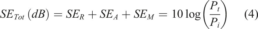
Here, the power of the incident electromagnetic waves is P
i
and the power of transmitted electromagnetic waves is P
t
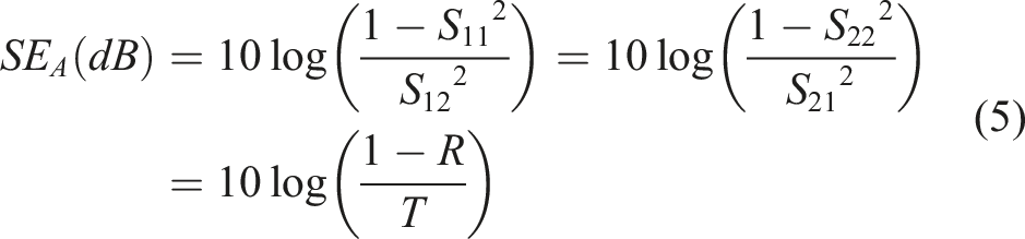
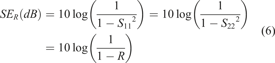
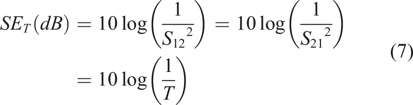
. The required SE
A
, SE
R
, and SE
T
parameters were calculated by using the following equations from 5 to 7 according to the measured S parameters with network analyzer.52,53
The penetration of electromagnetic radiation into an electrically conductive material is limited by its surface thickness, which is associated with charge current and polarization, sometimes referred to as the skin effect. The concept of skin depth is a critical parameter for evaluating the electromagnetic behavior of thin and reflective materials. It defines the distance an electromagnetic (EM) wave penetrates a structure before its intensity is significantly attenuated as it propagates toward the exit surface. By establishing the correlation between material thickness and skin depth, it is possible to quantify the extent of EM absorption—particularly that resulting from multiple internal reflections—and to characterize the structural efficacy of the composite.
51
The shielding efficiency of absorption is inversely related to the skin depth (δ), at which the field diminishes to 1/e of the incident value, with t representing the material’s thickness.51,54 The correlation between SEA and skin depth is determined using equation (8).5
55
Results and discussion
Cellulose fiber properties
The results of the analysis are given in Figure 5. Figure 5(a) shows the FTIR spectrum of the specimen to reveal the functional groups. The -OH group stretching in cellulose and adsorbed water is shown by the peaks at 3336 cm−1 and 1638 cm−1. The peak at 2879 cm−1 was assigned to the C-H group in glucose in polysaccharide ring cellulose. The symmetric bending of the -CH2 and -C-O-C vibration of the pyranose ring is responsible for the shoulder-shaped peak at 1421 cm−1 and the sharp peak at 1020 cm−1, respectively. Additionally, the β-glycosidic links (C-H and O-H bending) were liable for the peak at 895 cm−1.25,56,57 SEM imaging of the cellulose paper (Figure 5(b)) at 2000× magnification clearly reveals the fibrous network. Fiber diameters reach up to ∼10 µm, with a high density of finer fibers also evident, and lengths extending to several millimeters. The fibers form a complex, randomly oriented arrangement without a regular sequence. (a) FTIR spectrum and (b) SEM image of cellulose paper.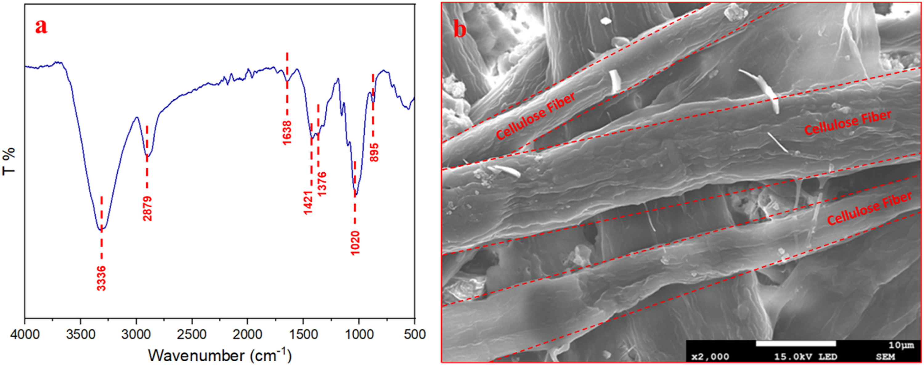
Tensile properties of HFRP composite
The results of tensile tests are presented in Figure 6 to demonstrate the combined effects of stacking sequence (G/C and C/G), interleaf architecture (Neat, Mid-plane, and All-plane), and cryogenic conditioning on the tensile response of the HFRP laminates. As is well established, the placement of glass (G) and carbon (C) plies strongly governs load sharing and stiffness: carbon fibers provide high strength and modulus, whereas glass fibers exhibit higher elongation-to-failure and lower stiffness, which can also influence the interlaminar response of hybrid laminates.5,58 According to research, it has been determined that positioning high-modulus carbon fiber in the outer layers improves tensile performance.
59
Consistent with this rationale, the C/G configuration (carbon fiber on the outer surfaces) achieved a tensile strength of 479 ± 25 MPa, while the G/C laminate (glass fiber on the outside) reached 422 ± 15 MPa (Figure 6(a) and (b)). The outer surface being made of carbon fiber corresponds to an increase of ∼14%. The stress–strain curves further support this stacking effect: the C/G lay-up exhibits a steeper initial slope (Figure 6(c)). Indicating a higher elastic modulus when carbon plies form the outer layers.
59
Stress–strain curves of (a) G/C, (b) C/G HFRP composite samples, (c) elastic modulus, and (d) strain to failure of HFRP composite samples for tensile loading.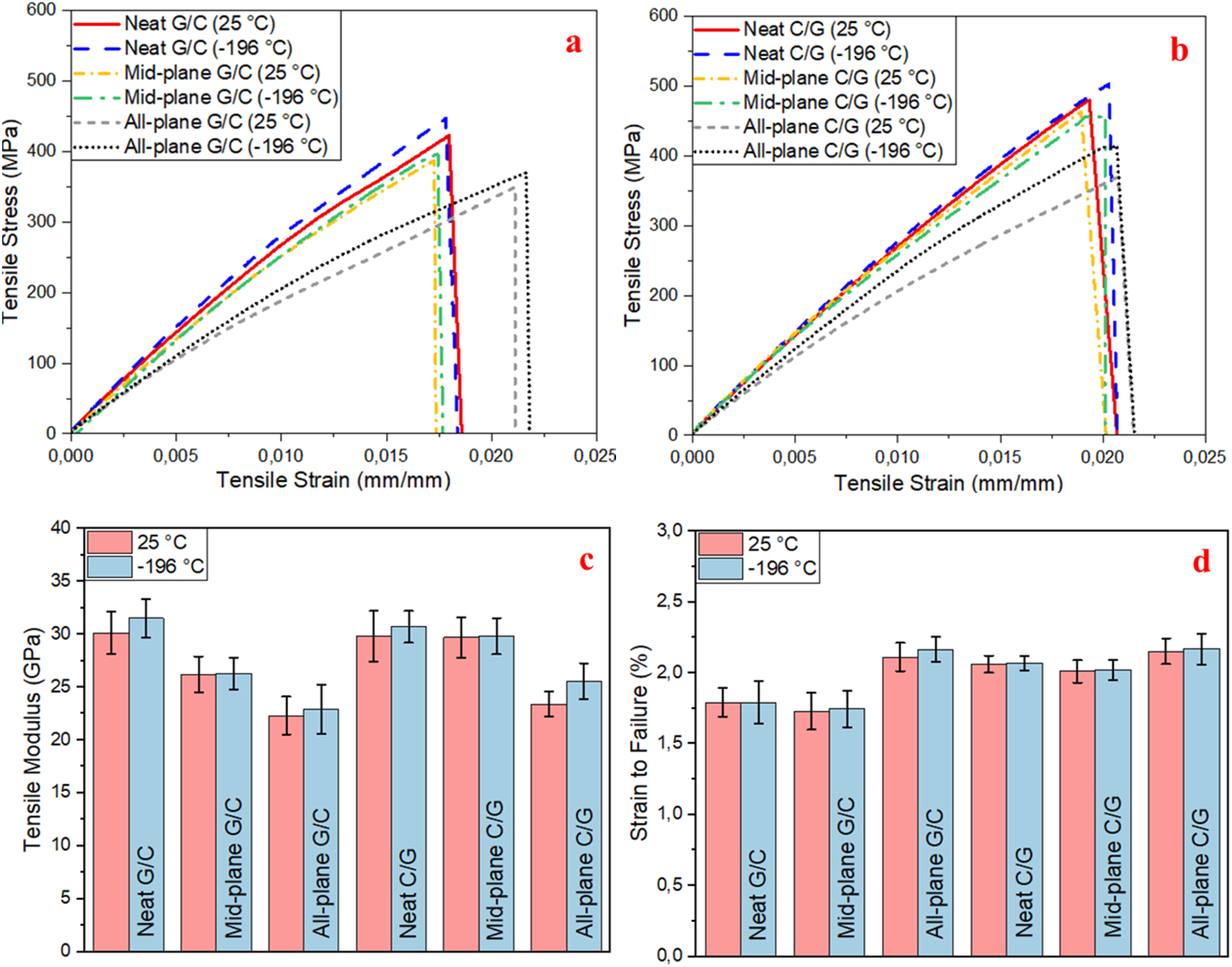
Building on the stacking-sequence baseline, the influence of cellulose-paper interleaves becomes clear when the interleaf area is increased from a single mid-plane to interleaves between all adjacent plies. For the G/C laminates (Figure 6(a)), tensile strength decreased from 422 ± 15 MPa (no interleaf) to 386.5 ± 35 MPa (mid-plane) and 350 ± 20 MPa (all-plane), i.e., reductions of approximately 8% and 17%, respectively. After cryogenic conditioning (−196°C for 30 min) and subsequent testing at room temperature, the corresponding tensile strengths increased to 446.8 ± 30, 397 ± 15, and 370 ± 30 MPa. Nevertheless, the same monotonic decline with increasing interleaf areas persisted (reductions of ∼11% and ∼17% relative to the conditioned reference). A similar trend was observed for the C/G sequence. At room temperature, tensile strength dropped by ∼3% with a mid-plane interleaf and by ∼23% with all-plane interleaves, while after cryogenic conditioning the reductions were ∼5% and ∼18%, respectively (Figure 6(b)). This conclusion is derived from the observation that the mid-plane of the paper-reinforced HFRP composite has a thickness of 2.1 mm, whereas the all-plane paper-reinforced HFRP composite has a thickness of 2.5 mm. Taken together, these results indicate that interleaf count is a dominant factor controlling tensile strength, regardless of stacking sequence, and that adding more cellulose interfaces progressively penalizes tensile performance.
This reduction is consistent with the microstructural consequences of introducing additional interlayers. Although microfiber-based interleaves can improve interlaminar fracture toughness, they may simultaneously reduce the effective fiber volume fraction, increase laminate thickness, and promote resin-rich regions and voids, all of which can undermine in-plane tensile properties. 60 Similar behaviors have been reported for other interleaf systems, for instance, high-density nylon 6,6 interlayers led to substantial losses in tensile strength alongside changes in laminate architecture. 61 In the present laminates, the observed tensile strength decreases (up to ∼23%) are therefore plausibly attributed to the creation of additional, mechanically weaker interlaminar planes that function as preferred sites for damage initiation and local strain concentration under axial loading.
Cryogenic exposure introduces an additional, yet superimposed, effect on the tensile response. Low-temperature conditions are known to increase matrix brittleness and stiffness and to generate residual stress because of thermal mismatch, which can modify interfacial load transfer, and the apparent modulus and strength measured at room temperature after conditioning.17,62 In line with this behavior, cryogenic conditioned specimens in this study generally exhibited higher tensile strength and modulus compared with their room-temperature counterparts (Figure 6(c)). Importantly, however, the conditioning effect does not reverse the interleaf-driven trend. Even after cryogenic conditioning, increasing the number of cellulose paper interfaces continues to reduce tensile strength, underscoring that the tensile strength drop is fundamentally linked to laminate architecture (i.e., interlaminar-plane density) rather than solely to temperature history. Comparable increases after conditioning have also been noted in cellulose paper–reinforced HFRP composites, supporting the notion that cryogenic exposure can enhance the apparent stiffness and strength, while the interleaf configuration primarily dictates the magnitude of tensile degradation.
Figure 6(d) illustrates that the failure strain of the HFRP composite with a neat G/C sequence is 1.79%, while the cryogenically conditioned sample has comparable failure strain characteristics. The failure strain in the cellulose-reinforced composite with a mid-plane is 1.72%, and the incorporation of paper in the mid-plane results in a 0.05% reduction in failure strain. The highest failure strain increase is seen in the all-plane cellulose-reinforced composite, measuring 2.11%. This indicates that adding cellulose paper to all planes reduces brittleness but adding paper to the middle plane increases brittleness (compared to the neat). The other configuration, the C/G-sequence HFRP composite, demonstrated a failure strain of 2.06%; the mid-plane paper-reinforced composite showed 2.01%; and the all-plane paper-reinforced composite recorded 2.15%. Likewise, the mid-plane of paper reinforcement reduces failure strain, but the cellulose paper reinforcement throughout all-planes amplifies failure strain. A similar situation regarding brittleness, observed in G/C-reinforced composites, has also been found in composites with this reinforcement configuration. The cryogenic conditioning of the test samples seems to have a minor effect on failure strain.
Fracture surface examination was carried out to clarify how cryogenic exposure alters the dominant damage mechanisms in the HFRP laminates after tensile loading. Representative post-test images are presented in Figures 7 and 8. For specimens of HFRP composites with G/C stacking sequence tested without cryogenic conditioning (Figure 7(a), (c) and (e)), the fracture morphology is governed primarily by interlaminar delamination, particularly in configurations where glass plies are positioned on the outer surfaces. Owing to their relatively high strain-to-failure, glass fibers can impose larger matrix strains, which promote matrix cracking and facilitate delamination initiation; consequently, placing glass fibers in the outer layers may intensify delamination damage.
63
As delamination typically nucleates at ply interfaces, its growth progressively reduces through-thickness integrity and load-transfer capability, leading to premature structural degradation of the laminate.
64
In agreement with this mechanism, the examined fracture regions show extensive layer separation, indicating that loss of interlaminar cohesion was the principal reason for the reduced load-carrying capacity. Despite the prevalence of delamination, localized fiber breakage is also evident, suggesting that once interfacial separation develops, the remaining intact plies experience elevated stress concentrations that can trigger final fiber failure. Tensile test damage of HFRP composites with G/C stacking sequence: (a) At room temperature without reinforcement, (b) Cryogenic conditioning without reinforcement, (c) At room temperature with paper reinforcement in the mid-plane, (d) Cryogenic conditioning with paper reinforcement in the mid-plane, (e) At room temperature with paper reinforcement in all-plane, and (f) Cryogenic conditioning with paper reinforcement in all-plane. The image of tensile test damage of HFRP composites with C/G stacking sequence: (a) At room temperature without reinforcement, (b) Cryogenic conditioning without reinforcement, (c) At room temperature with paper reinforcement in the mid-plane, (d) Cryogenic conditioning with paper reinforcement in the mid-plane, (e) At room temperature with paper reinforcement in all-plane, and (f) Cryogenic conditioning with paper reinforcement in all-plane.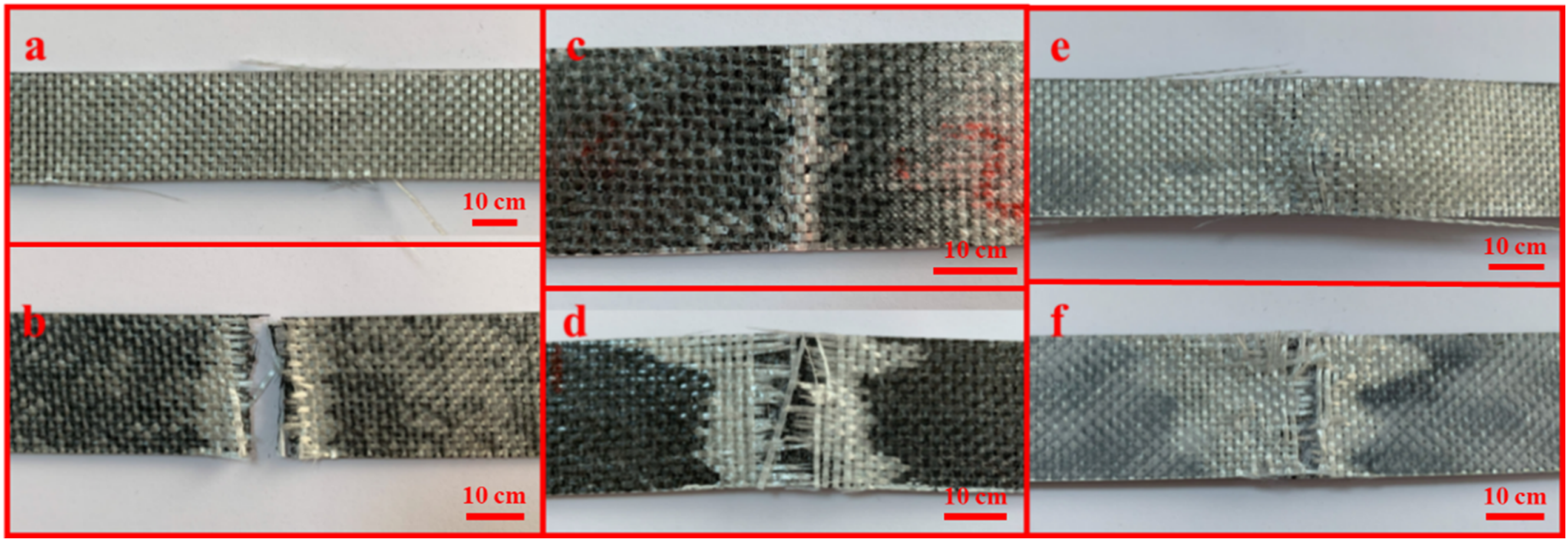
After liquid-nitrogen exposure for 30 min and subsequent testing at room temperature (Figure 7(b), (d) and (f)), the fracture morphology changes noticeably. Specimens fracture into two distinct pieces and the failure appears more abrupt and brittle, while the extent of delamination is reduced compared with the non-conditioned counterparts. This behavior consists of the well-known effect of cryogenic temperatures on polymer matrices, namely increased brittleness and stiffness, which can accelerate stress transfer to the fibers under tensile loading. Once the fiber load-carrying capacity is exceeded, damage develops rapidly and the fracture becomes unstable, producing a more brittle, catastrophic failure mode. 17 Overall, the micrographs indicate a transition from a delamination-dominated response at room temperature to a more brittle, fiber-dominated fracture after cryogenic conditioning, accompanied by a measurable reduction in delamination area.
Similarly, the tensile-induced damage in the C/G laminates is presented in Figure 8. Across both room and cryogenically conditioned specimens, failure was predominantly catastrophic, with the coupons separating into two distinct parts. Notably, at room temperature the C/G laminates tend to fail primarily by a through-thickness splitting mode rather than the extensive delamination observed in the G/C configuration. This behavior can be rationalized by the role of the outer carbon plies. Since carbon fibers dominate the axial load transfer in the C/G lay-up, increasing tensile stress promotes the formation of microcracks within the matrix and at interlaminar regions adjacent to the carbon layers. Given their lower strain-to-failure, carbon fibers are comparatively more prone to brittle fracture than glass fibers, which contributes to the abrupt splitting-type failure. As damage evolves toward the interior glass plies, the glass fibers can partially bridge developing cracks and locally restrain crack opening, thereby delaying crack propagation and helping preserve the overall load-carrying capacity to a limited extent. 58
Figure 9 presents optical micrographs of the tensile damage morphology in the G/C and C/G laminates. The incorporation of cellulose paper interleaves noticeably alters the failure behavior. Beyond the baseline features observed in the reference laminates, including interlaminar delamination and local fiber fracture, the interleaved specimens exhibit crack deflection at the paper layer, bridging and pinning effects, extended fiber pull-out, localized matrix microcracking, and interfacial debonding within resin-rich regions adjacent to the interleaf. Collectively, these mechanisms tend to segment delamination into shorter facets and mitigate the local crack driving force, which is consistent with prior observations that non-woven or fibrous interleaves suppress crack growth primarily through crack deflection and bridging processes.30,65 At the same time, the introduction of additional interfaces can create mechanically weaker planes under axial tension, offering a plausible explanation for the tensile-strength reductions observed with increasing interleaf count. Notably, Figure 9 also suggests that the cellulose paper can locally arrest crack advance, as evidenced by peeled regions and fractured cellulose fibers within the damaged zone. (a) G/C stacking sequence and (b) C/G stacking sequence HFRP composites with all-plane cellulose paper-reinforcement and microscope image of the damage resulting from tensile test.
Flexural properties of HFRP composite
The flexural response of the HFRP laminates was evaluated to clarify the combined influence of stacking sequence (G/C vs C/G), cellulose paper interleaving (mid-plane vs all-plane), and temperature history (room vs cryogenic conditioning). The flexural stress–strain curves obtained from three-point bending are presented in Figure 10 for both lay-ups. In all cases, the curves exhibit a distinct load drop prior to the maximum flexural strength, which can be interpreted as an early indication of damage initiation before catastrophic failure.
5
The subsequent sawtooth-type fluctuations suggest progressive damage accumulation during bending, including matrix cracking and interlaminar damage, rather than a single abrupt fracture event. Flexural stress–strain curves of (a) G/C, (b) C/G-HFRP composite samples for flexural loading, and (c) flexural strength of HFRP composite.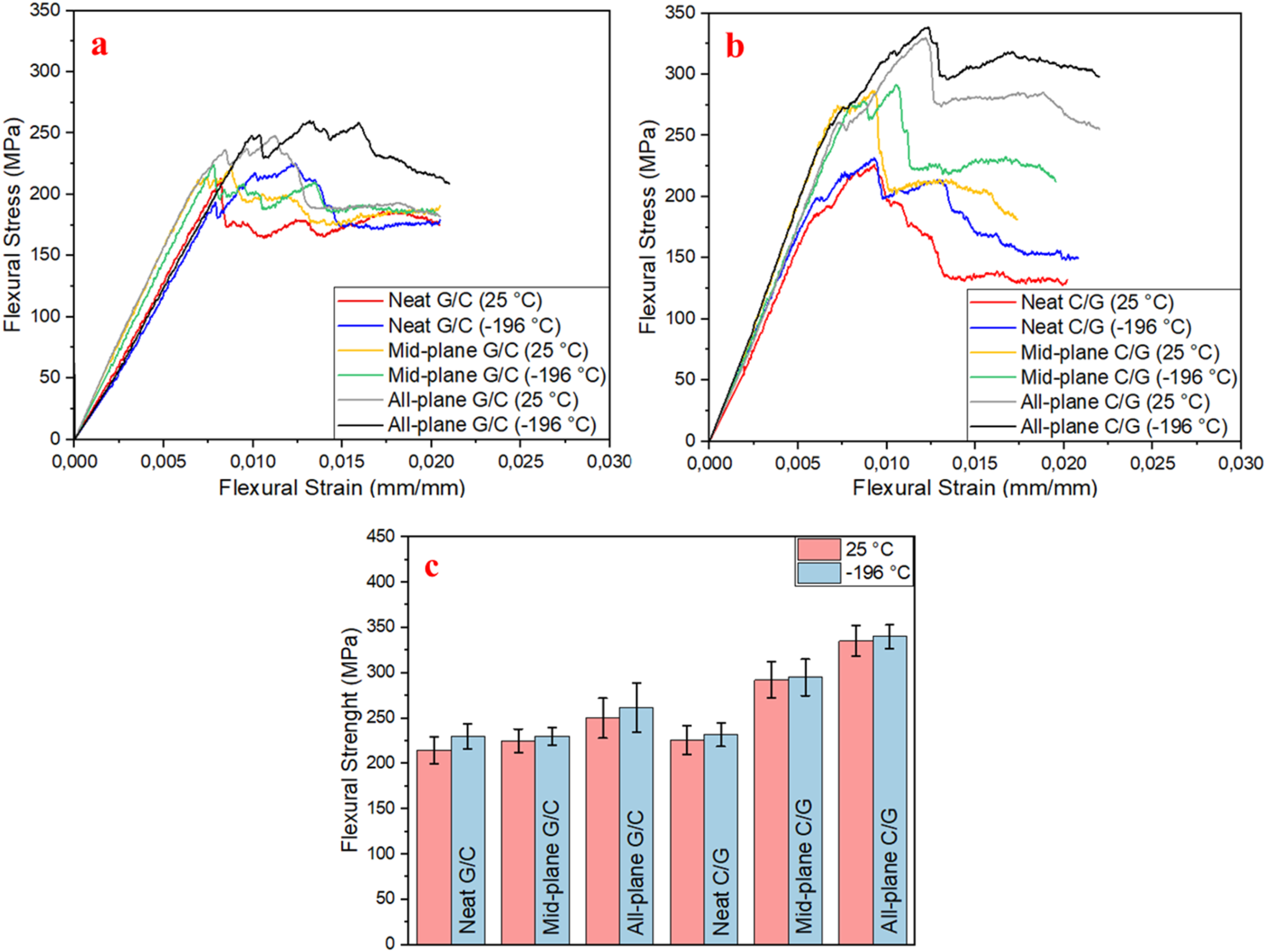
For the G/C laminates, the measured flexural strength increased systematically with interleaf content, rising from 215 ± 15 MPa (no interleaf) to 225 ± 13 MPa (mid-plane) and 250 ± 22 MPa (all-plane) (Figure 10(a)), corresponding to improvements of approximately 5% and 16%. This trend is consistent with the role of interleaves in strengthening the interlaminar region by promoting mechanisms such as crack deflection and fiber bridging, and increasing energy absorption during crack growth. 61 In addition, increasing the number of interfaces between dissimilar plies can intensify the hybrid effect and positively contribute to flexural performance. 9 After cryogenic conditioning, the same monotonic tendency was retained. The G/C laminates reached 228 ± 14, 230 ± 10, and 262 ± 27 MPa for reference, mid-plane, and all-plane configurations, respectively (Figure 10(a)). Notably, the mid-plane interleaf provided only a marginal benefit after conditioning, whereas the all-plane interleaving maintained a clear enhancement (∼15%). Overall, the all-plane interleaved G/C laminate exhibits comparable relative improvements in room and cryogenic condition states. Delamination and fiber fracture are the primary failure modes in composites that are subjected to cryogenic temperatures, as demonstrated by Meng et al. in their research. 18 On the other hand, they observe that the interface becomes stiffer as a result of thermal shrinkage of the polymer matrix due to temperature, necessitating a greater amount of energy for delamination.
The influence of stacking sequence becomes more pronounced when carbon plies are placed on the outer surfaces. Under flexural loading, maximum tensile and compressive stresses are concentrated near the outer skins; therefore, locating carbon fibers in the outer layers is advantageous for carrying bending loads. 5 In line with previous reports showing superior flexural performance for hybrids with carbon skins compared with glass skins,48,58 the C/G reference laminate achieved a flexural strength of 226 ± 16 MPa. More importantly, cellulose paper interleaving produced substantial gains in this configuration, increasing flexural strength to 292 ± 20 MPa (mid-plane) and 335 ± 17 MPa (all-plane). Since the square of the specimen thickness (h) is used in the flexural strength calculation, a 25% increase in thickness theoretically reduces the calculated strength by 56.25%. Despite these significant negative effects, the flexural strength in the results obtained increased by 48% (from 226 MPa to 335 MPa). After cryogenic conditioning, the corresponding values were 232 ± 13 MPa, 295 ± 20 MPa, and 340 ± 13 MPa (Figure 10(b)). These results demonstrate that interfacial reinforcement benefits both stacking sequences, yet the magnitude of improvement is markedly higher for the C/G hybrid composites, suggesting a synergistic interaction between outer-layer carbon reinforcement and interleaf-driven interlaminar toughening. 5 In summary, expanding and strengthening the interfacial network via cellulose paper interleaves significantly elevating flexural strength in HFRP laminates, with the most pronounced and temperature-resilient improvements achieved in the all-plane interleaved C/G configuration (Figure 10(c)).
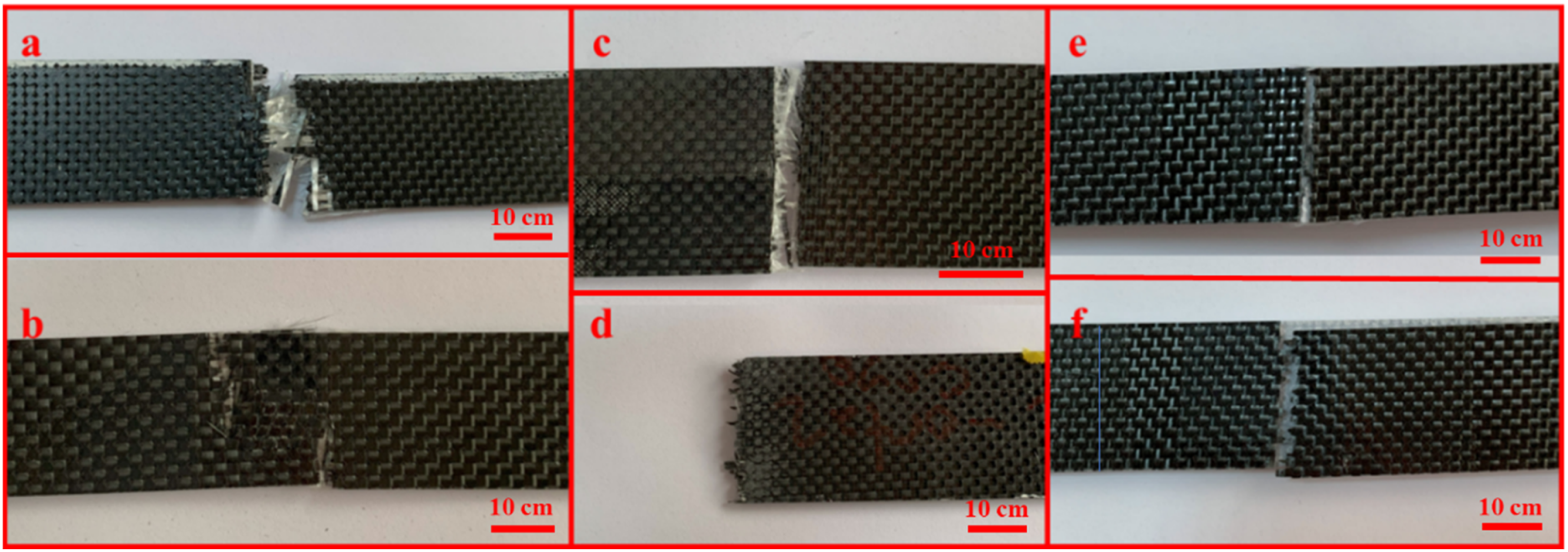
Macro-scale surface damage observed after the three-point bending tests is summarized in Figure 11. For the G/C laminate (Figure 11(a) and (b)), bending induced tensile stresses on the outer surface, leading to pronounced fiber fracture within the glass-rich tensile skin. With continued loading, damage evolved into interlaminar delamination between adjacent plies, which became more extensive toward the compression side of the specimen. Since delamination initiates and propagates along the interlaminar region, its morphology provides useful insight into the integrity of the fiber-matrix interface and the effectiveness of through-thickness load transfer.
49
In contrast, Figure 11(c) and (d) show a representative micrograph of the C/G laminate with all-plane cellulose paper interleaving. Although fracture of the carbon fibers is still evident within the tensile zone, the delamination features appear noticeably less dense and less continuous compared with the non-interleaved case. This observation suggests that the cellulose paper interleaf plays an active role in mitigating delamination growth, thereby delaying damage accumulation under bending. Mechanistically, the interleaf can promote fiber bridging and crack deflection across the interlaminar plane, increasing the energy required for delamination propagation and contributing to the higher flexural strength measured for the interleaved laminates. A similar bridging-assisted toughening effect of cellulose fibers has been reported in our earlier studies.
32
Microscope image of the damage of all-plane paper reinforced HFRP composites after a three-point bending test with (a) G/C stacking sequences at room temperature, (b) G/C stacking sequences at cryogenic conditioning, (c) C/G stacking sequences at room temperature, and (b) C/G stacking sequences at cryogenic conditioning.
Electromagnetic interference (EMI) shielding performance
The electromagnetic shielding properties of HFRP composites were investigated in terms of stacking sequences, cellulose paper reinforcement, and cryogenic conditioning. In this context, the investigations first address the behavior of the G/C and C/G sequenced samples under cryogenic conditions, respectively, and finally compare these two groups. Figure 12(a)–(d) show the total SE, absorbed SE, reflected SE graphs and the cumulative comparison of room and cryogenic environment conditioned HFRP composites with G/C configuration. As a result of EMSE measurements of non-cryogenic treated samples, the average SETot was measured as 36.8 dB for neat G/C sequenced HFRP composite, 40.5 dB for HFRP composite with paper reinforcement in the mid-plane, and 40 dB for HFRP composite with paper reinforcement between all-planes. Here it is seen that the paper reinforcement at the mid-plane of the composite increases the total SE. When the number of layers of cellulose increases and by applying to all-planes, total SE increases 3.7 dB compared to the neat HFRP sample. The obtained close values reveal that the number and location of paper layer reinforcement in G/C sequenced HFRP composites do not have a major effect. HFRP composites with a G/C sequence, which were conditioned at cryogenic conditions, revealed approximately 39.1 dB, 37.9 dB, and 34 dB average SETot value for without paper reinforcement, with paper reinforcement in the mid-plane, and with paper reinforcement in between all-planes, respectively. As can be clearly seen here, the SETot value of the sample without paper reinforcement increased after conditioning at cryogenic temperature, while the SETot value of both samples with paper reinforcement decreased. EMI shielding of G/C HFRP composites: (a) SETot, (b) SEA, (c) SER, and (d) Cumulative comparison.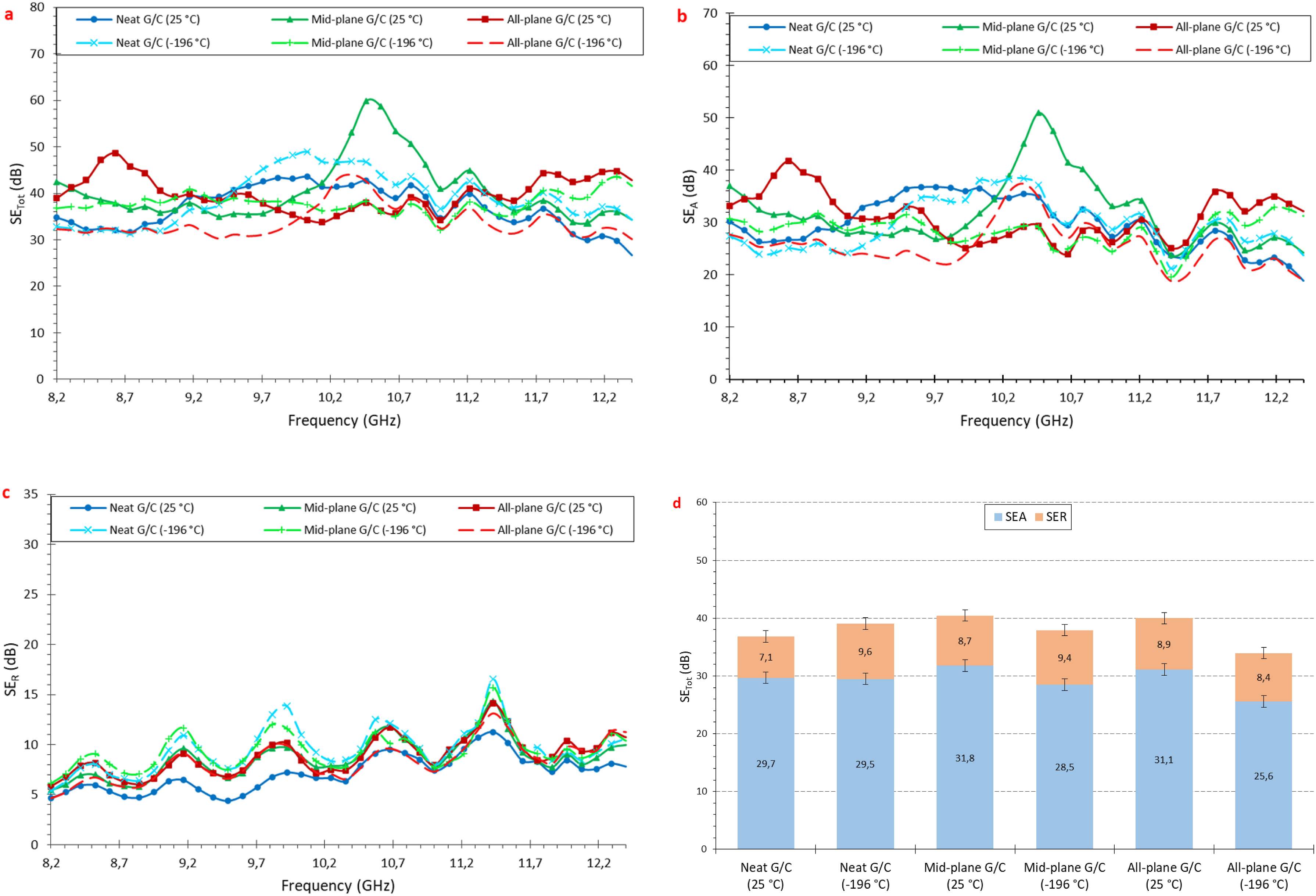
The total shielding effectiveness of HFRP composites with C/G configuration was measured as 45.9 dB, 49.6 dB, and 59.9 dB for non-paper reinforced, mid-plane reinforced and all-plane reinforced samples, respectively (Figure 13). Similar characteristics were observed with the G/C configured samples. Paper-reinforcement was improving the EMI shielding ability. The increase rate was calculated as 8% and 30% for C/G mid-plane paper-reinforced and C/G all-plane paper-reinforced samples, respectively. According to the previously given results, while the paper reinforced G/C sequenced samples do not give any difference for the mid-plane or all-plane paper-reinforcement, the C/G configured samples make high improvement with all-plane paper-reinforcement than the single mid-plane reinforcement. The total SE values of cryogenic conditioned C/G configured HFRP composites were measured as 58.2 dB, 48.5 dB, and 63 dB for without paper-reinforcement, with paper-reinforcement in the mid-plane, and with paper-reinforcement in between all-planes, respectively. The cryogenic conditioned neat samples give higher improvement of total SE values, mid-plane and all-plane paper-reinforced samples show less differences. The increase ratio was calculated as 26% for neat C/G sequenced sample. In addition, while 2% decrease was detected for the mid-plane paper-reinforced samples, contrary 5% increase was obtained for all-plane paper-reinforced samples, respectively. As a result, it can be said that cryogenic conditioning has a more positive effect on C/G sequenced samples compared to G/C sequenced samples. EMI shielding of C/G HFRP composites: (a) SETot, (b) SEA, (c) SER, and (d) Cumulative comparison.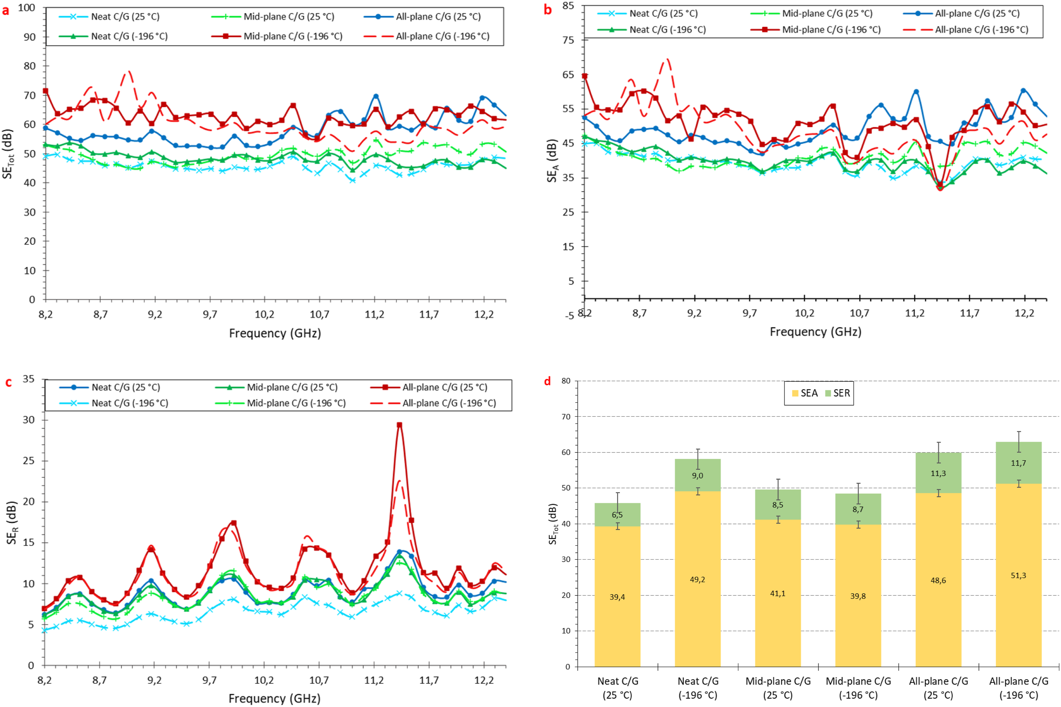
Power coefficients and SE loss values of the materials.
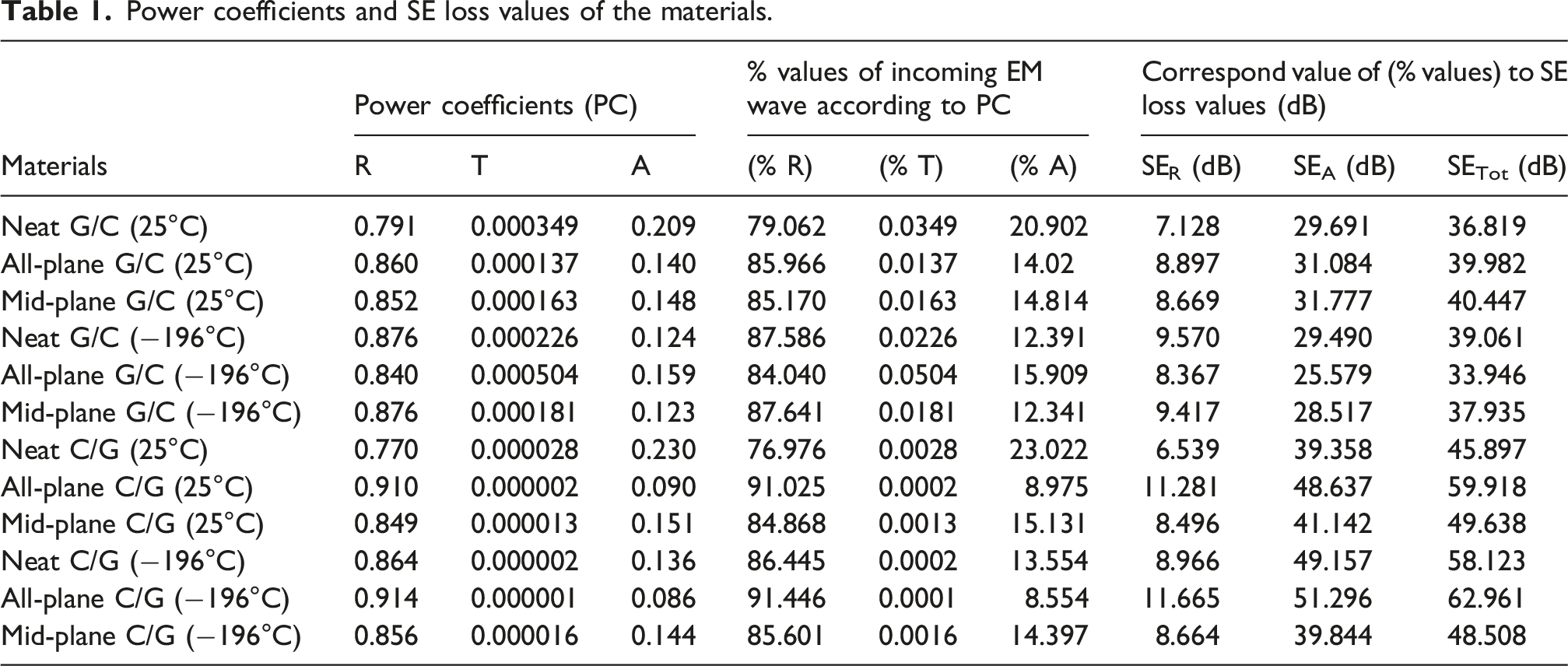
When the calculated power coefficients are examined in order to make an evaluation for all materials, it is seen that the surface reflection ratio (R) of the material is approximately 85% on average, and the power penetrating into the material (A) is around 15% on average. However, the shielding loss due to reflection (SER) is approximately 9 dB on average, and the EM loss absorbed and dissipated after penetrating the structure (SEA) is around 37 dB on average. This situation stems from the difference in character between linear percentage values and the logarithmic decibel scale.67–70 The percentage of electromagnetic waves that pass through the material and exit from another surface is approximately 0.014%. On the logarithmic scale, reducing the energy from 100% to 15% (after the reflection effect) corresponds to only a 9 dB attenuation; while the attenuation by absorption effect, of 15% to 0.014%, of energy penetrating into the material creates an attenuation of around 37 dB. In conclusion, according to the evaluation of the average total shielding efficiency (∼46 dB), approximately 80% of the total loss is dominated by absorption (SEA) and 20% by reflection (SER) mechanism. According to Hwang et al., 70 the true shielding character of a material should be defined by its dB-based SE components rather than by percentage ratios of coefficient based. Accordingly, these data prove that the tested material is not only a reflector but also a high-capacity electromagnetic absorber.67–70
It has been stated in the literature that surface enlarging factors such as intra-structure pores increase the inner reflection, which helps to the absorbance and getting higher total SE.51,54 Thus, it allows for more attenuation of the electromagnetic wave. The pores structure of cellulose fibers reveals that the paper reinforced samples have higher total SE values compared to both groups of G/C and C/G sequenced neat samples. It was observed that cryogenic treatment provided a clear improvement in both neat samples. Exposure to a cryogenic environment induces differential shrinkage due to the contrasting thermal expansion and conductivity properties of the carbon fibers, epoxy matrix, and cellulose regions, consequently increasing the density of micropores. This phenomenon is hypothesized to create numerous heterogeneous interfaces that facilitate the dissipation of incident electromagnetic energy into thermal energy via dipolar relaxation and conduction loss mechanisms. 71 On a macroscopic scale, the resulting voids and microcracks promote multiple internal reflections and scattering within the conductive carbon fiber networks. This effect aids in re-establishing the impedance match between the air and the composite material, which may have been partially disrupted.47,71–74 Furthermore, the porous architecture is suggested to stimulate electron transfer, generating micro-currents that dissipate as heat, thereby enhancing EMI shielding effectiveness. Literature concerning porous structures has extensively discussed this enhancement in EMI shielding, confirming the mechanism through comparative analyses with non-porous counterparts.47,74
The obtained gain of the EMI measurements of different sequenced HFRP composite is the C/G samples give higher SETot values than the G/C composites. The measured SETot values of G/C and C/G neat samples were 36.8 dB and 45.9 dB. The increase rate by only changing the sequences of carbon and glass layers was calculated as 24%. The SETot results of the G/C and G/C sequenced samples with paper reinforcement in the mid-plane are 40.5 dB and 49.6 dB, respectively. The increase rate here is approximately 22%. The SETot values of the samples with paper added to all-planes were measured as 40 dB and 59.9 dB for C/G and C/G sequenced. In this sample where only the carbon fabric was re-sequenced, the increase obtained was 49%. It is clear that the reason for the gains obtained in all these identical samples is the position of the carbon in the composite. To understand the improvement in SETot values here, it is necessary to explore the shielding mechanism of the electromagnetic (EM) wave. Electrical conductivity plays an important role in attenuating EM waves on the material and high conductivity is not compulsory and 1 Ω/cm volume resistivity is acceptable.34,75–77 The electrical conductivity of the hybrid composite developed in this study could not be measured. The challenges encountered in quantifying the electrical conductivity of hybrid composite structures primarily arise from the high dielectric properties of the glass fiber layers and the epoxy matrix. Although carbon fiber layers possess inherent high conductivity, the glass fiber fabric acts as an insulating barrier between carbon layers, thereby preventing the formation of a continuous conductive network throughout the material. Particularly in through-thickness measurements, insulating resin-rich regions and glass fiber layers restrict interfacial contact between carbon fibers, causing the electrical resistance to exceed the detection limits of the measurement instrumentation. Consequently, the electrical decoupling effect induced by the glass fiber layers renders the DC conductivity measurement of such hybrid configurations highly challenging, if not impractical.78,79 This difficulty was further exacerbated in our study by the inclusion of additional cellulose layers. As highlighted in the literature for similar hybrid systems, such architectures exhibit macroscopic insulating behavior; however, this does not adversely affect electromagnetic interference (EMI) shielding performance at high frequencies, as the shielding mechanism is sustained through capacitive coupling and multiple internal reflections.78,79
In shielding process, EM waves move through the structure, they are dispersed by electrical charge transportation and are absorbed by converting to heat.35,80,81 Therefore, the width of the conductive mesh is important. Since the epoxy matrix is an insulator, it is completely permeable to EM waves. In other words, epoxy has no efficient shielding ability.
82
It can be predicted that, besides the glass fiber that totally insulates, the conductive reinforcement material used, carbon fiber will build the conductive network within the structure and thus increase the SE capacity. This is one of the strategies to make the composite as hybrid with carbon. However, the skin effect phenomenon needs to be investigated to understand why the total SE is higher in C/G sequenced HFRP composites where carbon is in the first place, even though the same type and number of reinforcement materials are used. The skin depth, which is the effective thickness that EM waves are absorbed by dispersing in the material and is related to frequency, material permeability, and conductivity.54,83 According to the literature, carbon fiber shielding materials enhance impedance mismatch in EMI shielding due to increased skin depth.
51
Since the material developed in this study incorporates carbon fiber components and provides EMI protection based on conductive rather than magnetic mechanisms, the calculated coefficients indicate a reflection-dominant shielding behavior. However, the presence of hybridization-induced micro-voids—which facilitate internal reflections and increase electromagnetic wave attenuation—alongside the applied cryogenic treatment, renders the skin effect a critical parameter for characterizing the carbon-glass-cellulose composite. The calculated skin depth of the G/C and C/G configured neat samples was 0.597 mm and 0.450 mm, respectively. The other skin depth values of the G/C mid-plane, C/G mid-plane, G/C all-plane, and C/G all-plane samples were 0.557, 0.431, 0.741, and 0.438, respectively (Figure 14). The values show the C/G sequenced samples have nearly the same thinner skin depth values and the increase in absorbance when the reference thicknesses are the same as the other samples. Another word, the EM waves required thinner material thickness for attenuation due to the high conductivity of carbon. In the shielding process in C/G sequenced samples, the EM waves first penetrate the carbon fabric layer. Thus, even though they penetrate the same distance in the composite from outer surface to core with the G/C sequenced samples, they hit more carbon layers. With wider conductive mesh of the carbon fabric, the absorbance of entering EM waves increases. EMI shielding comparisons of G/C versus C/G configured HFRP composites: Skin depth values.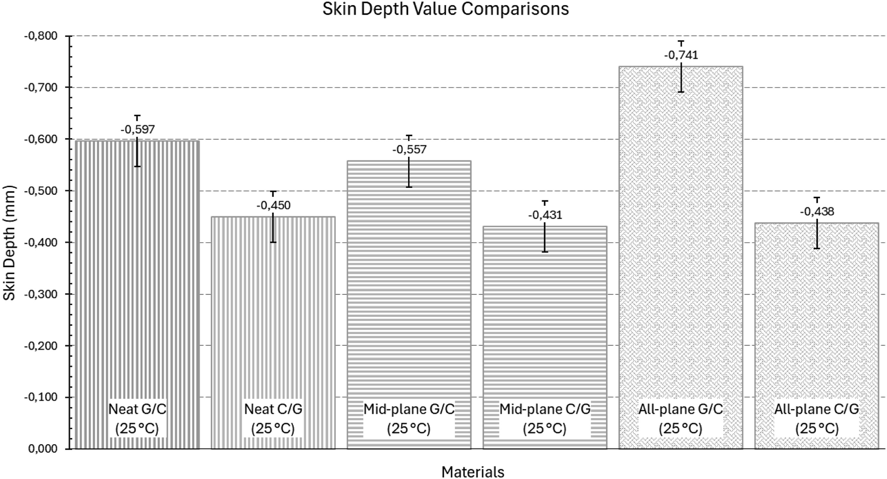
Conclusions
In this study, the effects of cellulose paper interlayers and stacking strategies on the mechanical performance and electromagnetic interference (EMI) shielding behavior of glass/carbon hybrid fiber-reinforced polymer (HFRP) composites were comprehensively investigated under both room-temperature and cryogenic conditions. The main findings are summarized below: • Configurations where carbon fibers are positioned in the outer layers (C/G) provided an approximately 14% increase in tensile strength (from 422 MPa to 479 MPa) compared to configurations where glass fibers are on the outside (G/C). • Adding cellulose interlayers in all planes reduced tensile strength by approximately 23% but increased the material’s ductility and reduced brittleness by raising the elongation at break from 1.79% to 2.11% in the G/C configuration and from 2.06% to 2.15% in the C/G configuration. • In contrast to the decrease in tensile strength, the fiber bridging and crack deflection mechanisms provided by the cellulose interlayers have resulted in a significant improvement in flexural strength. These mechanisms are explained with the help of micrographs. In particular, in the all-plane C/G configuration, flexural strength increased from 226 MPa to 335 MPa, representing an approximate 48% increase. • Cryogenic conditioning (−196°C) increased tensile and flexural strengths; it raised the tensile strength of neat G/C to 446.8 MPa and the flexural strength of all-plane C/G to 340 MPa. • All samples exceeded the commercially required 30 dB shielding limit. The all-plane C/G configuration exhibited the highest total shielding effectiveness (SETot), with 59.9 dB at room temperature and 63 dB after cryogenic treatment. • It was determined that approximately 80% of the total shielding effectiveness is attributable to absorption (SEA). It was confirmed that the porous structure of cellulose and the micro voids formed as a result of cryogenic shrinkage facilitate the attenuation of electromagnetic energy by increasing multiple internal reflections.
Cellulose papers are inherently hydrophilic. Even as an interlayer, microcracks will eventually be opened by operating stresses that lead to moisture ingression when coated with a hydrophobic epoxy matrix and evaluated under regulated humidity conditions (50 ± 10% relative humidity). Such moisture exchange acts as a plasticizer and poses a risk of long-term degradation of interfacial load transfer. Evaluating the hydrothermal aging and long-term environmental stability of these hybrid composites is of significance for future research. Consequently, cellulose-based interlayers provide significant enhancements in flexural strength, toughness, and electromagnetic interference shielding capability in hybrid composites, although with a regulated compromise in tensile strength. The results of this study demonstrate that the modified composites provide a versatile and sustainable material solution for advanced engineering applications, including aircraft, space, and energy storage systems, which are susceptible to cryogenic and electromagnetic conditions.
Footnotes
Funding
The authors received no financial support for the research, authorship, and/or publication of this article.
Declaration of conflicting interests
The authors declared no potential conflicts of interest with respect to the research, authorship, and/or publication of this article.
Data Availability Statement
Data will be made available on request.