
Abstract
To address the challenges of high cost, complex wiring, and electromagnetic interference in the online monitoring of composite pressure vessels, this paper proposes a wireless pressure monitoring method based on passive ultra-high frequency (UHF) RFID technology. A 2D axisymmetric finite element model of an aluminum-lined, glass-fiber-wrapped dual-layer cylinder was established using COMSOL Multiphysics to analyze the mechanical response under internal pressures ranging from 0 to 20 MPa. By constructing a force-electrical coupling model, the modulation mechanism was revealed, showing a “redshift” in the antenna’s resonant frequency and a linear attenuation of the Received Signal Strength Indicator (RSSI) induced by strain. Considering the curved features of the vessel, HFSS simulations were utilized to analyze the effects of different curvatures on tag performance, confirming a systematic evolution law where tag gain and read range decrease as the cylinder radius increases. Graded tensile experiments verified that the measured signal evolution trends are highly consistent with simulation predictions, with RSSI and surface strain exhibiting a significant linear negative correlation across the full range. This study successfully validates the “Pressure-Strain-Signal Strength” sensing logic, providing a wireless, passive, and low-cost solution for the full lifecycle health management of composite pressure vessels.
Keywords
Introduction
Composite pressure vessels, particularly Type IV and Type V all-composite containers, have been widely applied in fields such as hydrogen storage and transportation, aerospace, and natural gas vehicles due to their high specific strength, lightweight properties, and excellent corrosion resistance. 1 However, these vessels are subjected to cyclic internal pressure loads during long-term service, and their failure modes are complex, typically originating from the accumulation of micro-damage at the fiber-matrix interface and potentially leading to catastrophic burst failure. 2 Finite element analysis and experimental studies indicate that failure generally initiates in the “knuckle region” where the cylinder transitions to the dome, with fiber breakage occurring when the internal pressure reaches a critical value. 3 Consequently, real-time, online monitoring of internal pressure and the resulting surface strain is critical for assessing structural integrity, predicting remaining life, and achieving predictive maintenance. 4
To meet the growing demands for monitoring, academia has explored and applied various structural health monitoring (SHM) techniques based on physical properties. Traditional SHM techniques, such as acoustic emission (AE) and fiber Bragg grating (FBG) sensors, have been applied to damage detection and strain measurement in composite pressure vessels. As a passive monitoring method, acoustic emission technology can capture transient elastic waves generated by internal material damage and is frequently used to determine the first-ply failure pressure. By detecting the transient elastic wave energy released due to damage evolution during the loading process, real-time detection and localization of damage are achieved. 5 In the field of optical fiber sensing, FBG technology has garnered significant attention due to its immunity to electromagnetic interference and quasi-distributed measurement capabilities. Researchers have utilized FBG sensing data to achieve real-time characterization of the vacuum level in aerospace vacuum pressure vessels, 6 and have successfully implemented effective monitoring of vacuum leakage states in pressure vessels through quasi-distributed FBG sensing techniques. 7 Other studies have achieved continuous structural health monitoring throughout the entire service life by winding sensing fibers spirally and circumferentially around polymer liners during the CFRP manufacturing process. 8 Research by Alblalaihid et al. developed a linear capacitance-based sensor embedded within glass fiber and Kevlar fiber reinforced polymer composites for strain monitoring and early damage detection. 9 Lu et al. developed a high-performance strain sensor based on laser-induced graphene/polydimethylsiloxane (A-LIG/PDMS) for monitoring and locating impact damage in composite structures. 10 Barragán et al. reported on a new generation of embedded printed sensors for near-field monitoring of high-performance composites. 11 Bertram et al. proposed a “tag-like” sensor concept that integrates temperature-compensated full-bridge strain gauges, digital temperature sensors, and RFID transponders to wirelessly monitor resin infusion, the curing process, and mechanical loads during service. 12 Garcia-Etxabe et al. investigated the potential of embedding amorphous ferromagnetic microwires into composite materials to serve as wireless stress sensors. 13 Since dimensional changes in a rectangular patch antenna in both horizontal and vertical directions lead to linear shifts in its resonant frequency, it serves as an excellent strain sensor. 14 This frequency shift phenomenon has been widely applied in the monitoring of internal damage, 15 surface cracks, 16 and strain 17 in composite materials.
However, despite certain progress made with existing technologies, traditional wired sensor systems still face significant bottlenecks in large-scale practical engineering applications. First, their deployment typically requires complex wiring, which not only increases installation costs and complexity but also makes large-scale, distributed integration difficult to achieve on filament-wound pressure vessels with rotationally symmetric structures. 18 Second, the physical connection points between sensors and readout equipment often become weak links in reliability, being susceptible to damage in harsh industrial environments or under dynamic loads. Furthermore, many wired sensing solutions are prohibitively expensive and may negatively impact the mechanical properties of the composite structure itself, failing to meet the economic requirements for large-scale commercial applications. 19 In addition, in specific application scenarios such as hydrogen energy, pressure vessels may face environments with strong electromagnetic interference, which imposes higher demands on the stability and anti-interference capabilities of traditional wired sensors that rely on electrical signal transmission. Consequently, there is an urgent demand in both industry and academia for an online pressure monitoring technology that is wireless, passive, low-cost, and easy to integrate. Such a technology must be seamlessly integrated onto the surface or within the interior of composite vessels to provide long-term, reliable monitoring of mechanical strain caused by internal pressure loads—without compromising structural performance—thereby providing critical data input for structural health management and safety assessment. 20
In the pursuit of more efficient monitoring solutions, passive Ultra-High Frequency (UHF) Radio Frequency Identification (RFID) technology stands out due to its unique energy transmission and communication mechanisms. This technology is an automatic identification method that achieves non-contact, bidirectional data communication and energy transfer via radio frequency signals. The basic system consists of a reader and a tag attached to the object being identified. The tag does not require a built-in power supply; its operating energy is derived entirely from the interrogation radio waves emitted by the reader. 21 This zero-power consumption characteristic is one of the core features of passive RFID technology, allowing it to demonstrate immense potential in scenarios requiring long-term, maintenance-free monitoring.
UHF-band (typically 860–960 MHz) RFID technology offers faster transmission rates and smaller antenna sizes, and it is capable of reading a large number of tags in a short time, making it suitable for large-scale distributed monitoring. 22 Furthermore, chipless RFID sensors further enhance these advantages in SHM. By removing the silicon chip, these sensors possess a simpler structure that enables ultra-low-cost, printable manufacturing and direct integration into composite material fabrication processes. 23 Chipless RFID sensors are typically based on frequency encoding, where the resonant frequency is sensitive to physical quantities such as strain and cracks. 24 In the field of SHM, particularly for complex structures like composite pressure vessels, passive UHF RFID technology has emerged as an attractive wireless sensing solution due to its unique advantages. Qiang Wang et al. discussed the importance of structural health monitoring and strain sensing in detail, systematically demonstrating the fundamental principles and component architecture of RFID technology. Furthermore, their research introduced various strain sensor design schemes, including passive, active, semi-passive, UHF, chipless, and multi-sensory RF-based systems, while elucidating their respective performance advantages. 25 Reza Arablouei et al. proposed a novel RF signal enhancement technique based on photoluminescence to improve the sensitivity of 3D-printed passive RFID sensor arrays. Depending on the propagation mode (near-field or far-field), this technique can increase the received signal level by 2 dB to 8 dB, effectively mitigating data loss issues without altering transmission power or the number of sensors.26,27 Sarma et al. designed a novel “smart skin” sensor employing sensitive microwave structures composed of cascaded split-ring resonators coupled with coplanar waveguide transmission lines. This sensor is capable of identifying the initiation and propagation of cracks in architectural structures, enabling continuous monitoring of damage at any surface point and supporting the simultaneous detection of multiple structural disturbances. 28
In the field of composite materials monitoring, Daniel Visan et al. introduced a wireless system integrated with machine learning models specifically for monitoring CFRP structures in aerospace. The system collects data via carbon nanotube (CNT) piezoresistive sensors embedded within the CFRP layers and transmits it wirelessly to a central server for intelligent processing. 29 Kang et al. conducted an in-depth review of technologies such as CNTs, piezoelectric materials, RFID, wireless sensing, optical fibers, and computer vision in structural monitoring, clarifying the working principles, deployment status, and future research directions for each. 30 Additionally, Alassane et al. developed a wireless induction node specifically designed for monitoring reinforced concrete structures. As part of a cyber-physical system, this node utilizes an embedded design that requires no battery power, achieving energy autonomy and long-term monitoring through radiative electromagnetic wireless power transfer. 31
In summary, passive UHF RFID technology has laid a solid technical foundation for the construction of zero-power, full-lifecycle autonomous wireless sensor networks. By combining the energy harvesting and communication capabilities of RFID with low-power sensing technologies, fully passive sensing nodes can be developed to achieve long-term, large-scale, real-time structural monitoring. This technical approach circumvents the challenges of battery replacement and maintenance inherent in battery-dependent systems, providing a viable technical solution for the full-lifecycle health management of composite pressure vessels.
Pressure monitoring mechanism and force-electrical mapping theory
Mechanical analysis of pressure vessel deformation under pressure
When filament-wound composite pressure vessels are subjected to high-pressure gas loads, their stress state exhibits typical axisymmetric characteristics. To explore the mechanical response laws of the vessel during the 0–20 MPa pressure cycling process and to establish a quantitative mapping model between the internal pressure
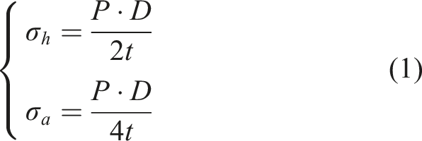
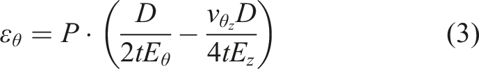
By substituting the stress components and rearranging the terms, the theoretical mapping model describing the relationship between the cylinder’s internal pressure and surface strain can be obtained, as shown in equation (3).
RFID tag strain sensing mechanism
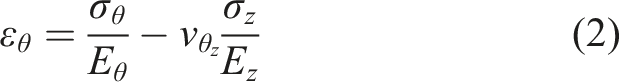
When an RFID tag attached to the surface of a GFRP laminate is subjected to a tensile load along the fiber direction, the tag antenna undergoes synchronous deformation with the substrate. Within the elastic range, this geometric deformation directly alters the electrical length of the antenna, thereby leading to a shift in the resonance frequency.
Assuming the dipole antenna is subjected to tension along its longitudinal direction (length direction) and the longitudinal strain of the substrate material is


According to transmission line theory, the resonance frequency of a half-wave dipole antenna is inversely proportional to its electrical length. By substituting equation (4) into the resonance frequency formula, the instantaneous resonance frequency under the loaded state can be obtained:
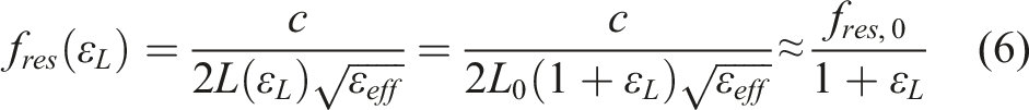
As shown in equation (6), an increase in tensile strain
This equation 32 indicates that the rate of change in the antenna’s resonance frequency is numerically approximately equal to the applied mechanical strain, but in the opposite direction.
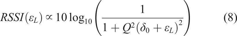
Similar to the logic used in curing monitoring, the reader emits signals at a fixed frequency, such as 915 MHz. On the surface of the composite material, the tag is initially in a detuned state. When tension occurs, the resonance frequency shifts further toward lower frequencies (redshift), causing the resonance peak to move further away from the reader’s carrier frequency. This process exacerbates impedance mismatch, causing the system’s operating point to slide down the falling edge of the resonance curve, or away from the peak. According to the Lorentzian line-shape characteristics of the power transmission coefficient, as shown in equation (8), the RSSI signal will exhibit monotonic attenuation as strain increases.
Numerical simulation of force-electrical coupling based on COMSOL
Finite element modeling of internal pressure response in gas cylinders
To achieve efficient simulation of the mechanical behavior of the gas cylinder, this section utilizes the “Solid Mechanics” module in the COMSOL Multiphysics multi-physics simulation platform to establish a finite element model based on 2D Axisymmetric spatial dimensions. By exploiting the rotational symmetry of the cylinder structure, computational complexity can be significantly reduced and convergence speed improved while maintaining calculation accuracy.
Geometric characterization
A dual-layer shell geometric model, comprising an Aluminum Liner and a Composite Layer, was established for the research object. The specific dimensions of the model are set as follows: the internal radius Geometric view of the cylindrical section generated by 2D axisymmetric rotation.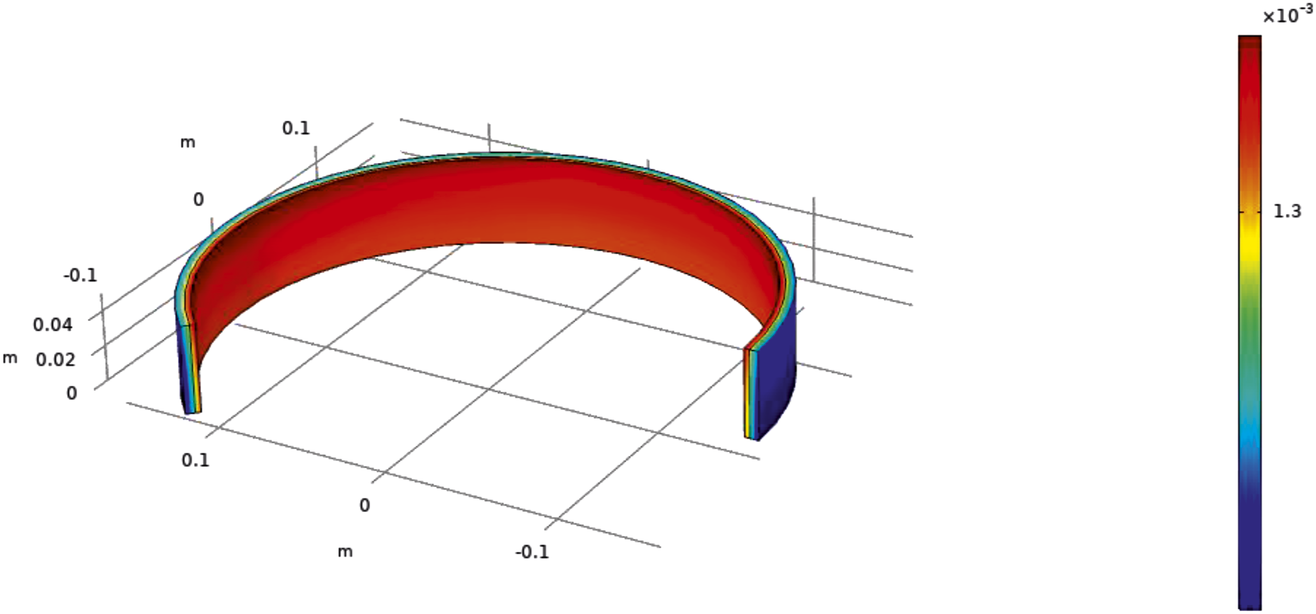
Material properties and constitutive models
The model assigns distinct material properties to different layer domains to simulate realistic mechanical responses: An Isotropic Linear Elastic model was adopted. The Young’s modulus was set to
Fiber reinforcement direction (Direction 1): Mapped to the circumferential direction (
Loading and boundary conditions
To simulate the pressurized conditions of the gas cylinder in actual operation, the model boundary conditions are set as follows:
Internal load
A normal boundary load is applied to the innermost surface of the aluminum liner. Using the Parametric Sweep function, the pressure
Displacement constraints
A Roller constraint is applied to the bottom edge of the geometric model. This setting restricts the axial displacement at the bottom (
Meshing and solver settings
A Free Triangular Mesh is used to discretize the geometric domains, and second-order triangular elements are selected to enhance solution accuracy. Local mesh refinement is performed at the interface between the liner and the composite layer, as well as on the outer surface areas, to ensure the accuracy of the strain gradient collection. Regarding the solver settings, a Stationary Solver is selected, which works in conjunction with the parametric sweeper to extract the structural responses under different pressure steps.
Electromagnetic simulation model of the sensing tag
To quantitatively explore the modulation mechanism of the surface strain of glass fiber composite gas cylinders on the electromagnetic characteristics of RFID tags, this study established a simulation model based on the COMSOL Multiphysics platform, incorporating the RF Module and structural mechanical features.
Antenna geometric topology and refined modeling
The sensing tag prototype selected for this study is the Alien 9662 UHF RFID tag. As shown in Figure 2, a 1:1 geometric reconstruction was performed based on the actual physical dimensions to restore the real physical response in the simulation. The main structure of the antenna adopts a typical Meander Line Dipole configuration, which aims to increase the effective electrical length within a limited physical space through the bending structure, thereby reducing the resonance frequency to the ultra-high frequency (UHF) operating band. During the geometric modeling process, the antenna was placed at the center of the substrate, with its key structural parameters set as follows: Construction of tag antenna simulation model.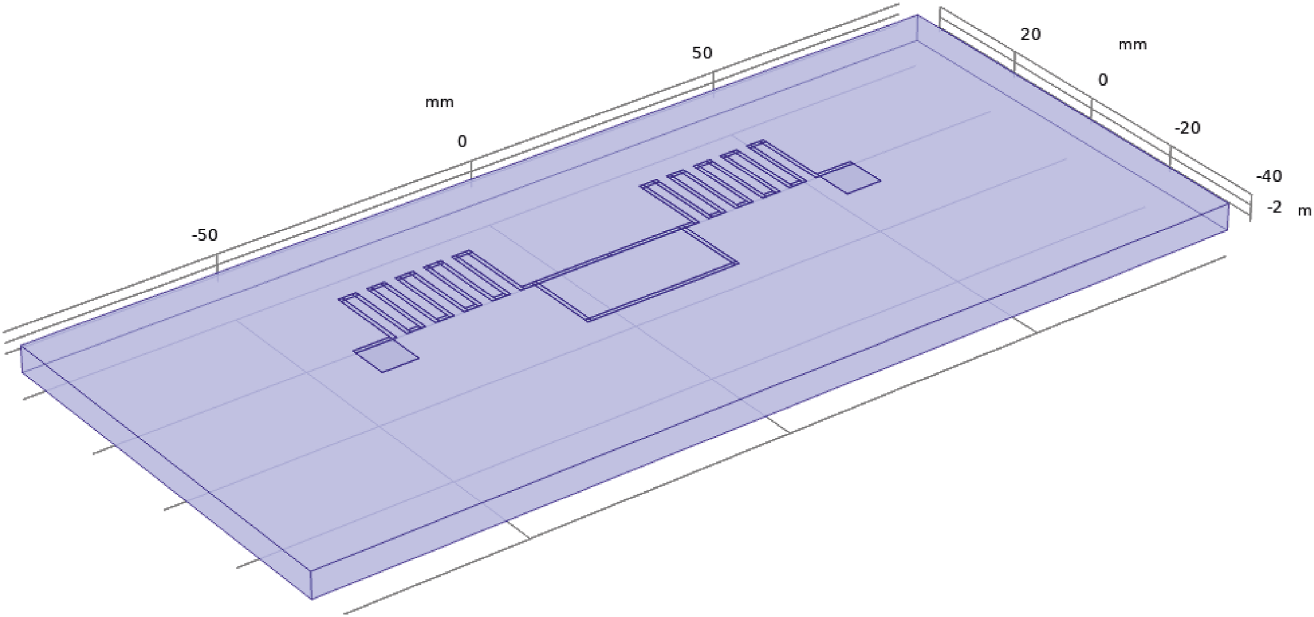
Radiation element design
To match the 915 MHz center operating frequency set for this study, the optimized total antenna length (
Impedance matching network
A T-Match Loop structure is used at the center of the antenna for interconnection with the chip. The loop length (
Wire specifications
The trace width (
Material properties and dielectric environment definition
The substrate material in the simulation model is used to simulate the cylindrical wall of the filament-wound glass fiber gas cylinder. Based on the actual operating conditions of composite cylinders, the substrate material is defined as FR-4 (equivalent to Glass Fiber Reinforced Polymer, GFRP). Its relative permittivity is set to
Port excitation and conjugate impedance matching
In the radio frequency (RF) simulation, the chip is not constructed as a physical geometric model but is instead represented by an equivalent Lumped Port. The port is positioned at the feed gap in the center of the T-match loop, with a gap width ( Schematic diagram of lumped port excitation setup for chip positions.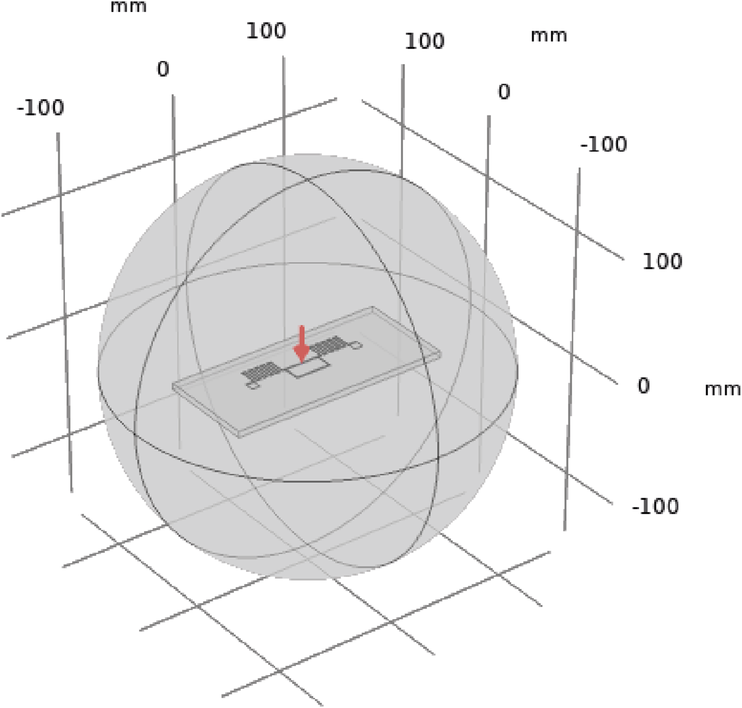
Simulation results and analysis
Finite element analysis of pressure vessel deformation under pressure
Distribution characteristics of surface strain field on the gas cylinder
Figure 4 illustrates the 3D strain distribution contours of the entire gas cylinder and its longitudinal section under an internal pressure of 20 MPa. As shown in the figure, the gas cylinder exhibits significant radial expansion characteristics after being pressurized. In the central region of the cylinder body, the distribution of the first principal strain (i.e., hoop strain) demonstrates extremely high uniformity; the color transition in the contour plot is smooth, with no evident stress concentration phenomena observed. Schematic diagram of lumped port excitation setup for chip positions.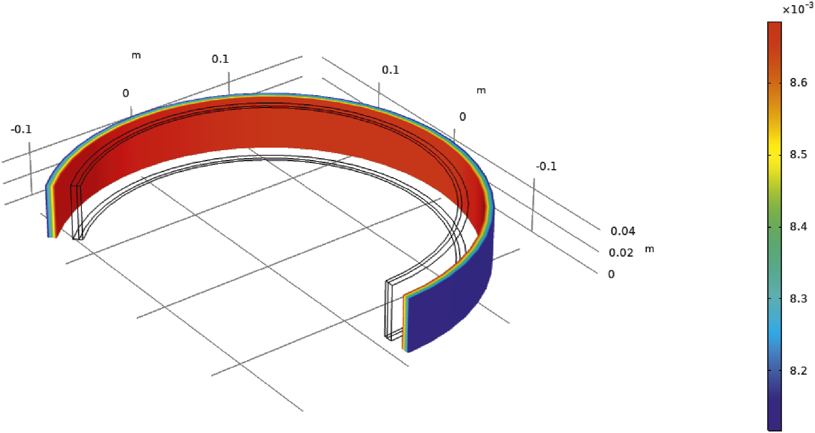
This demonstrates that in regions far from the constraints of the domes, the mechanical response of the gas cylinder aligns with the ideal stress state of a thin-walled cylindrical shell. Further observation of the sectional strain gradient reveals a slight decreasing trend in strain values from the liner toward the outer surface of the composite material. This occurs because, during the synergistic deformation of the dual-layer structure, the external fiber layer serves as the primary load-bearing component, while the liner is mainly responsible for sealing.
Under the 20 MPa full-scale operating condition, the maximum circumferential strain on the outer surface is approximately
Quantitative evaluation of internal pressure–strain response
Data table for comparison of circumferential strain under different internal pressure loads.
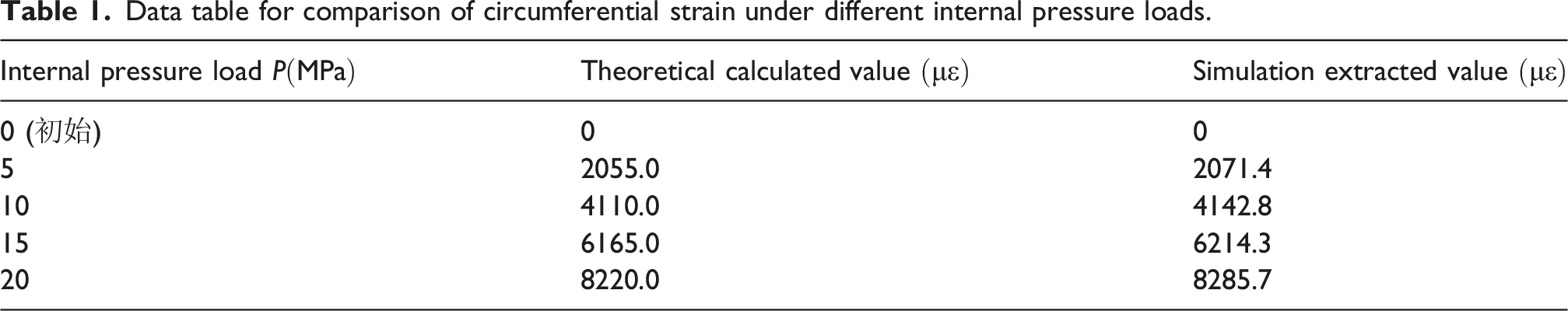
Performing a linear regression on the simulation data, the resulting response equation is
It should be noted that the finite element model established in this study focuses primarily on the cylindrical mid-section of the gas cylinder, simplifying the analysis by neglecting the boundary constraint effects of the domes on the shell. In actual working conditions, the transition region between the dome and the cylinder exhibits significant strain gradients and complex stress states due to geometric discontinuities, which introduces a degree of non-uniformity into the pressure-strain mapping logic of that area.
Consequently, the monitoring method proposed in this paper is currently most applicable to the uniform strain zone in the middle of the cylinder. In future work, we intend to establish a complete 3D model of the cylinder including the dome structures to conduct an in-depth investigation of the constraint effects in the transition zone and their specific impact on radio frequency signal modulation, thereby further expanding the monitoring coverage of the sensing system.
Impact of strain on tag parameters
By observing the energy distribution on the antenna surface in Figure 5 and extracting the Surface Current and Near-field Electric Field Norm (Norm E), it is found that the current is mainly concentrated in the T-match loop and the initial sections of the meander arms. This demonstrates that the T-match structure effectively achieves power matching between the chip’s complex impedance and the antenna radiator. Surface current vector distribution plot.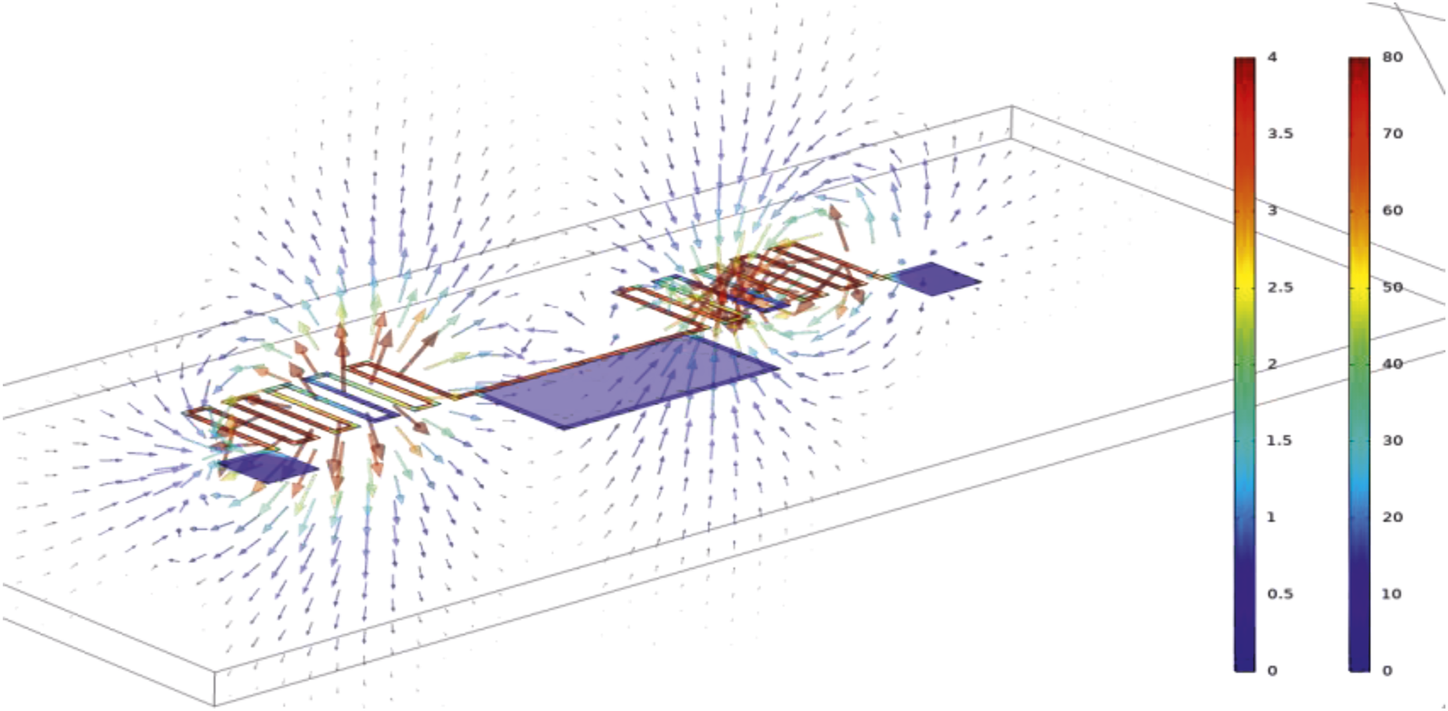
As the internal pressure of the gas cylinder increases, the axial tensile strain generated on its surface gradually increases from 0 to Comparison of return loss (S11) curves under different strains.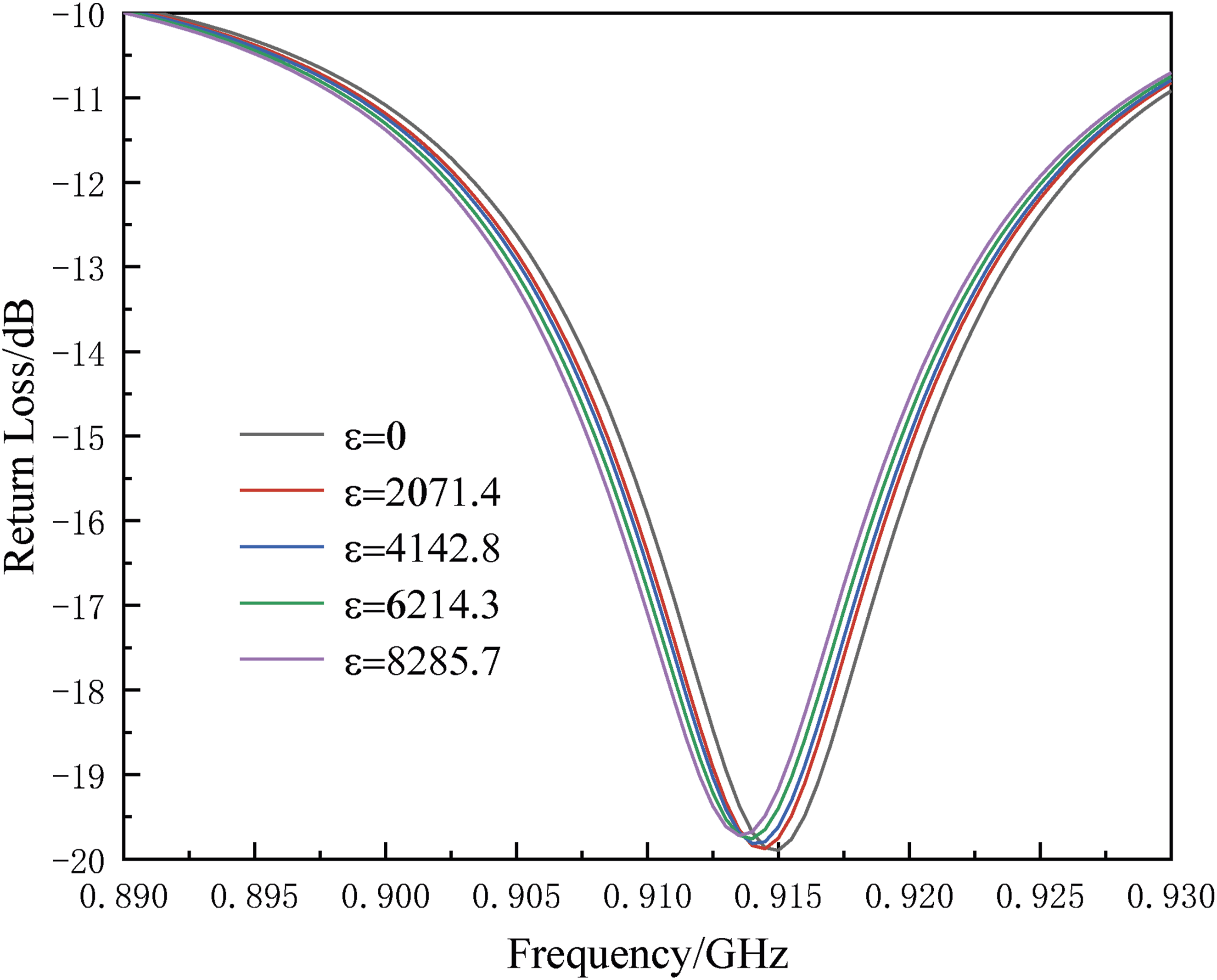
It is observed that as strain increases, the minimum point of the S11 curve (i.e., the resonance frequency) undergoes a distinct leftward translation, exhibiting a significant “redshift” characteristic. This is because the axial tension directly leads to an increase in the physical length of the antenna’s meander arms, which in turn increases the effective electrical length of the antenna. Experimental results indicate that the resonance frequency shifts continuously downward from the initial 915 MHz to approximately 913.5 MHz. Although the observed resonance frequency redshift within the 0 to 20 MPa pressure range is relatively small, this variation is sufficient to trigger a significant sensing response. According to Lorentzian lineshape characteristics, a minor frequency shift causes a severe impedance mismatch between the antenna and the chip, thereby converting mechanical deformation into a monotonic attenuation of the RSSI. Considering that the Impinj R420 reader used in the experiments possesses millisecond-level time resolution and high-precision signal strength detection capabilities, the signal fluctuations generated by a redshift of this magnitude are far above the environmental noise floor of the system, ensuring the robustness of the pressure monitoring logic.
To quantitatively evaluate the sensing sensitivity of the system, this study extracted the resonance frequency values under different strain states and performed a linear regression fit, as shown in Figure 7. The figure illustrates the linear fitting relationship between the resonant frequency and the surface strain. The fitting equation is Linear fitting of resonance frequency versus strain.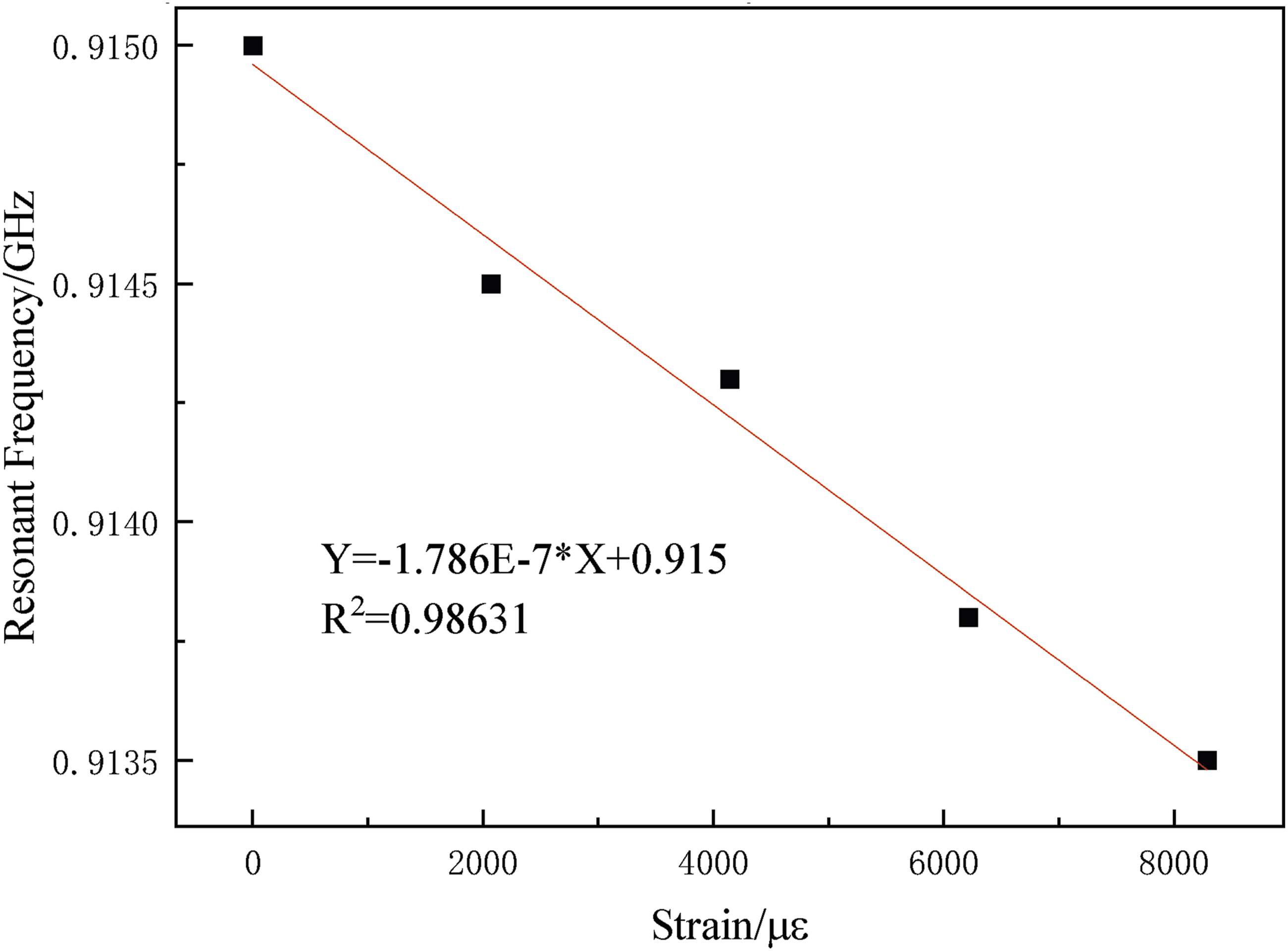
Analysis of the RSSI mapping model
Based on the modified Friis backscatter transmission equation, the spectral distribution curves of the sensing tag’s reflected signal strength under different strain levels were obtained through simulation. As shown in Figure 8(a) as the strain gradually increases from 0, the spectral envelope of the signal strength exhibits significant asymmetric evolutionary characteristics. It can be seen from the spectral evolution trend that the position of the resonance peak undergoes a significant redshift as strain increases, which remains highly consistent with the previously described shift in S11 parameters. Simultaneously, the continuous degradation of the impedance matching state, caused by the antenna’s geometric deformation under strain, leads to a decrease in reflected power across various frequency points to varying degrees. Characterization of reflected signal intensity response to strain. (a) Spectrogram of reflected signal intensity. (b) Linear fitting of RSSI versus strain at a fixed frequency.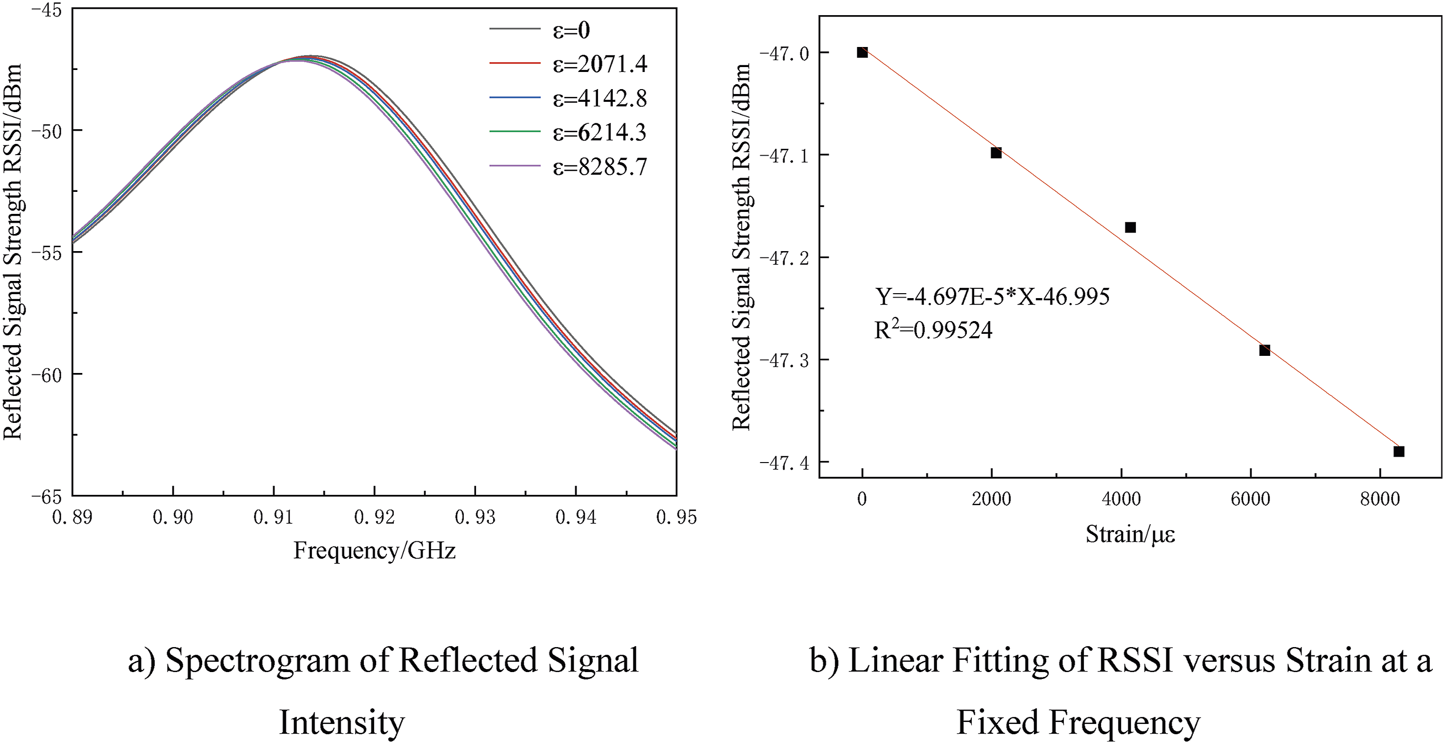
Simulation mapping table of cylinder internal pressure, surface strain, and RF signal characteristics.
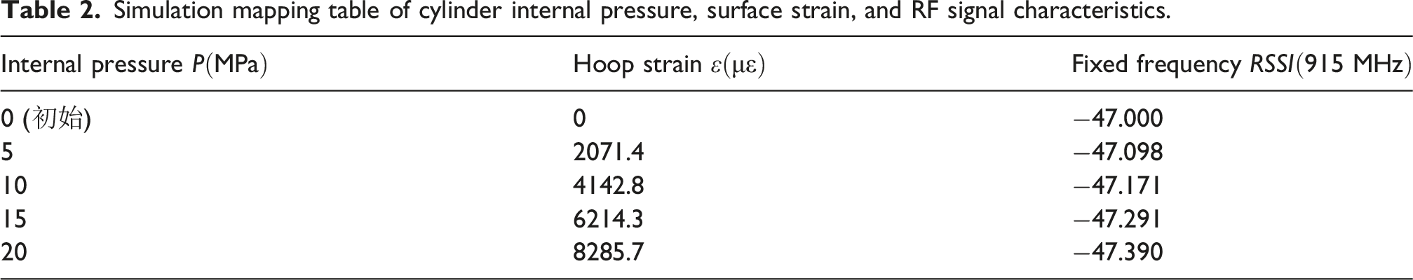
As shown in the table, during the process of increasing the internal pressure of the gas cylinder from 0 MPa to 20 MPa, the RSSI value at the fixed frequency (915 MHz) attenuates monotonically from −47 dBm to −47.39 dBm. The Impinj R420 reader used in this study features a signal strength resolution of 0.1 dB. The observed variations are significantly higher than the hardware detection threshold, which is sufficient to support reliable pressure monitoring. To further quantify the sensing performance of this indicator, a linear regression analysis was performed on the fixed-frequency RSSI and strain data, and the results are illustrated in Figure 8(b).
Although the peak intensity of the reflected signal in Figure 8(a) shows only slight fluctuations with increasing strain, its impact on sensing performance is primarily reflected in the response at a fixed frequency point. Since the RFID reader operates under a single carrier at 915 MHz, the redshift of the resonance peak causes the operating state at this specific frequency to shift downward along the edge of the Lorentzian envelope. Figure 8(b) displays the linear regression analysis between RSSI and strain at a fixed frequency, yielding the fitting equation:
Although the Lorentzian lineshape described by equation (8) possesses intrinsic nonlinearity, the RSSI attenuation observed in this study exhibits significant linear characteristics. This is primarily because, during the pressure cycling from 0 to 20 MPa, the maximum surface strain produced is approximately
Analysis of the impact of curvature on tag response characteristics
Composite cylinders are typical curved structures, and in practical applications, tags are usually attached to a cylindrical surface with a specific curvature. Compared to a flat installation state, surface attachment further alters the geometric configuration of the tag antenna, the current distribution paths, and the surrounding electromagnetic boundary conditions, thereby affecting its impedance matching state. Therefore, based on the experimental results of flat specimens, it is necessary to further analyze the impact of curvature factors on the tag’s response characteristics.
To analyze the mechanism of curvature’s effect on the tag’s electromagnetic properties, and with reference to the equivalent analysis method for cylindrical cavities, the tag dielectric structure attached to a cylindrical metal surface can be approximated as a cylindrical cavity model. In this case, the conductor surface and the grounded cylindrical surface are treated as electric wall boundaries, while the dielectric layer forms an equivalent resonant cavity. Under the curved state, the electric field distribution within the cavity satisfies the wave equation in cylindrical coordinates, as shown in equation (9):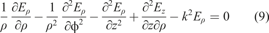
Furthermore, the expression for the resonant frequency of the tag antenna can be derived as equation (11):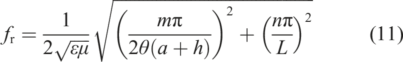
As indicated by the above equation, the resonant frequency is directly related to the cylinder radius and the bending angle. When a tag transitions from a flat state to a curved attachment state, both its equivalent electrical length and the cavity mode conditions undergo changes, leading to a shift in the resonance point. Simultaneously, variations in curvature alter the electric field storage state and power dissipation within the cavity, which in turn affects the radiation efficiency and radiation gain of the tag antenna. For passive UHF RFID tags, these changes are ultimately reflected in key electromagnetic performance indicators such as the power transmission coefficient, gain, and read range. Consequently, it is evident that curvature is a significant factor influencing the electromagnetic response characteristics of the tag.
To verify the aforementioned mechanisms at the simulation level, this study established a 3D electromagnetic model in HFSS featuring a tag antenna attached to the surface of cylindrical metallic objects with varying radii. While maintaining constant structural parameters, material properties, and excitation conditions for the tag, only the cylinder radius was varied—specifically at 15 mm, 20 mm, 25 mm, 30 mm, and 35 mm—to analyze the tag’s transmission coefficient, antenna gain, and read range.
Figure 9(a) presents the 2D radiation pattern of the tag when attached to the surface of a cylindrical object. As shown in the figure, the tag maintains a distinct primary radiation direction under cylindrical surface conditions; however, its radiation morphology differs from the ideal flat state. This indicates that changes in curvature exert an influence on the far-field radiation distribution of the tag antenna. Figure 9(b) illustrates the relationship between the tag antenna’s read range and frequency under different cylindrical radii. The results show that near 915 MHz, there are significant differences in the read range across the various radii. Furthermore, as the cylinder radius increases, the peak read range gradually decreases. This demonstrates that curvature not only shifts the resonant state of the tag but also further impacts the ultimate read/write performance. RFID tag performance under different curvature conditions. (a) The radiation pattern of a tag attached to a cylindrical surface. (b) Under different radius conditions, the read range curves of the tag antenna.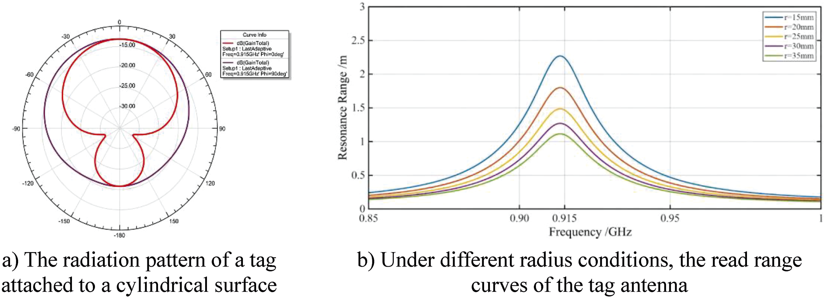
Simulation results of the tag antenna mounted on cylinders of different radii.
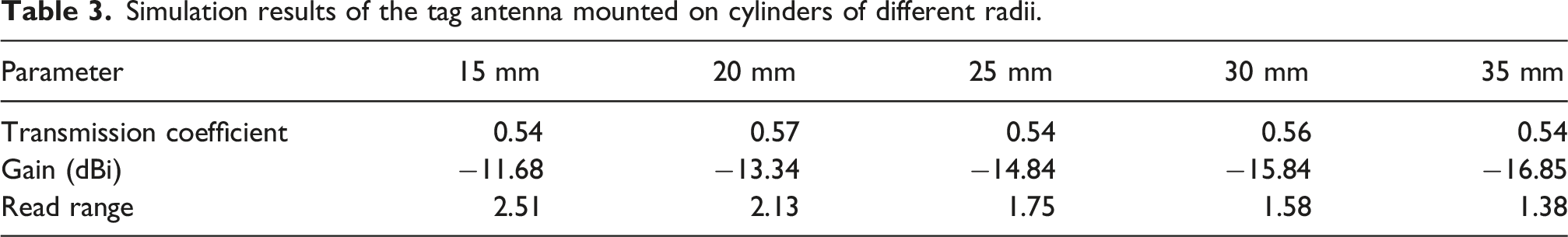
Based on the combined theoretical analysis and HFSS simulation results, it can be concluded that curvature exerts a systematic influence on the electromagnetic response characteristics of the tag by altering its initial detuning state, electric field distribution, and radiation capability. Consequently, while experiments on flat specimens can reveal the fundamental response patterns of the tag to strain variations, the additional effects brought about by curvature must be further considered when extending these findings to real-world curved composite cylinder scenarios.
Experimental validation and data discussion
Experimental materials and specimen preparation
The experimental specimens were fabricated using glass fiber fabric reinforcement combined with epoxy resin to form the composite material representing the tested samples. The glass fiber fabric used has a density of 130
To ensure consistency in the curing quality of the composite materials, the specimen preparation process was conducted in a controlled laboratory environment. During preparation, the ambient temperature was strictly maintained at 25 ± 2°C, and the relative humidity was kept at 50 ± 5%. To investigate the influence of substrate structural dimensions on sensing characteristics, two types of equivalent specimens with different thicknesses were prepared by controlling the number of material stacking layers, as shown in Figure 10: 1. Thin Specimen: Fabricated using a 4-layer symmetrical stacking sequence, aimed at simulating the sensing response of thin-walled sections of gas cylinders or low-pressure vessels. 2. Thick Specimen: Fabricated using an 8-layer symmetrical stacking sequence, used to evaluate the impact of increased dielectric thickness on radio frequency (RF) energy attenuation and strain transfer sensitivity. Characterization of reflected signal intensity response to strain.
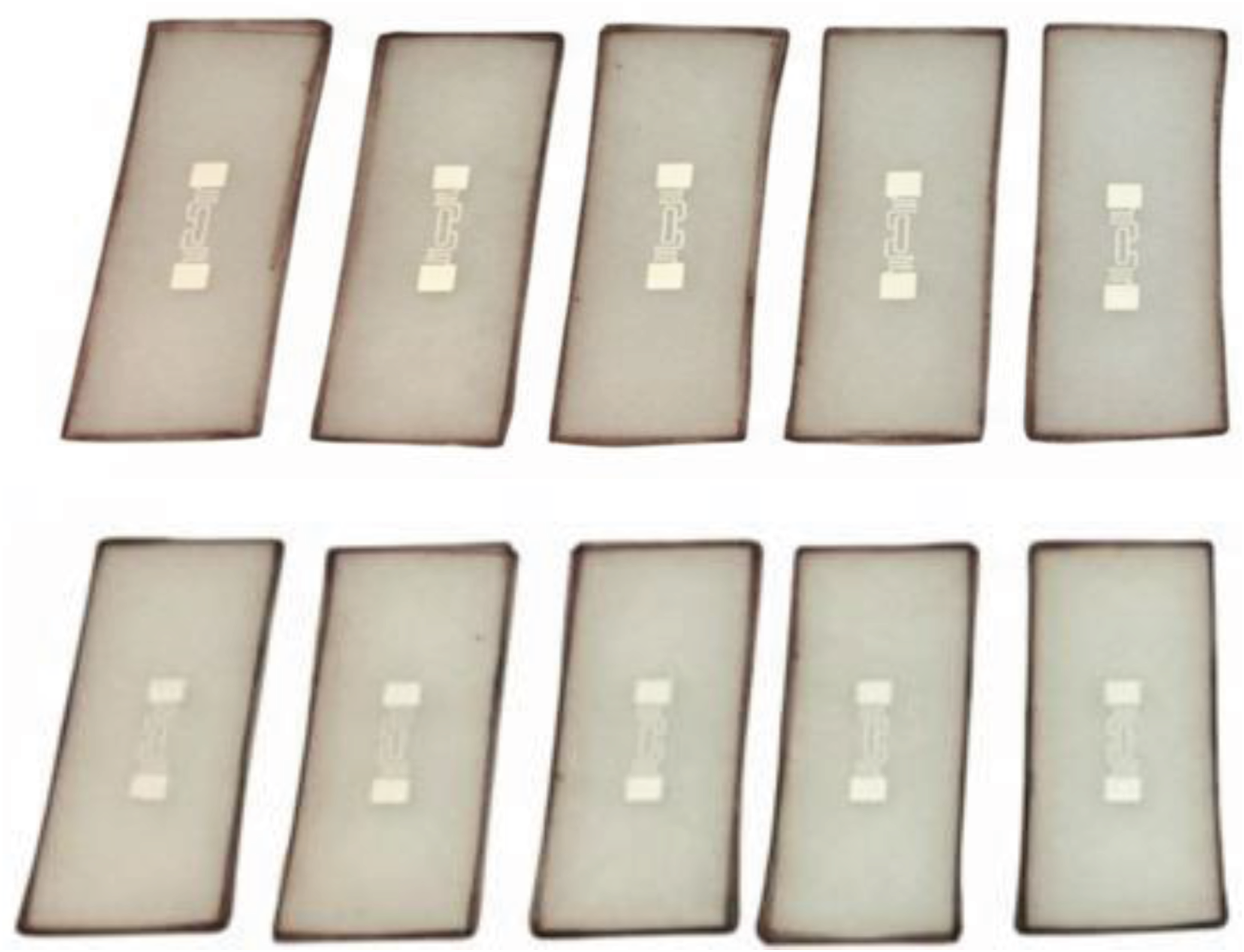
The lamination process was conducted on a glass surface without additional vacuuming or traction operations on the top. The samples were allowed to air-dry naturally for 24 h and were then peeled from the glass surface after curing, followed by mechanical processing to achieve a uniform shape.
The sensing unit consists of an RFID tag and metal foil resistance strain gauges, forming a collaborative monitoring system that enables cross-validation of experimental data. A high-strength, low-loss epoxy adhesive was utilized to attach the tag to the geometric center of the specimen. To ensure the fidelity of strain transfer, the longitudinal axis of the tag’s meander dipole must be strictly aligned with the tensile axis of the specimen. A resistance strain gauge was attached to the back of the specimen, symmetrical to the RFID tag’s position; this gauge serves as the “gold standard” for strain measurement, providing real-time monitoring of the actual strain values during the tensile process.
The bonding of the resistance strain gauges followed a standardized procedure: First, the predetermined locations on the specimens were lightly sanded with 400-grit sandpaper to remove surface laitance, followed by repeated wiping with anhydrous ethanol until no visible impurities remained. Subsequently, an appropriate amount of high-strength cyanoacrylate adhesive was applied, and the strain gauge was precisely aligned with the central axis of the specimen. During the bonding process, constant finger pressure was applied for approximately 60 s to expel air bubbles and ensure an extremely thin and uniform adhesive layer. Finally, the specimens were left undisturbed for over 1 h to guarantee complete strain transfer integrity. Figure 11 illustrates the antenna sensor integrated onto the specimen surface along with the five metal foil resistance strain gauges used for benchmark calibration below it. Physical GFRP flat specimen and sensor integration layout.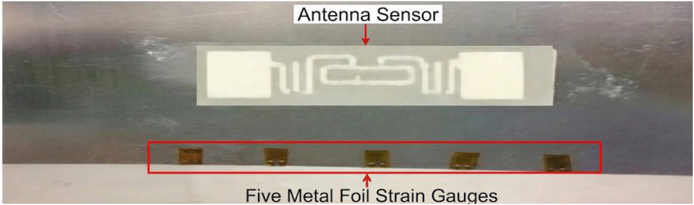
Experimental setup and synchronized data acquisition
In terms of hardware link construction, the load application module utilized an Instron 5985 microcomputer-controlled electronic universal testing machine. This equipment possesses a load capacity of up to 200 kN and micron-level displacement control precision, providing a robust quasi-static tensile load for the GFRP specimens. The specimens were vertically secured using the testing machine’s high-performance hydraulic grips. During the clamping process, the gripping pressure was strictly set to 0.3 MPa, a parameter that effectively avoids local crushing damage to the composite substrate.
For strain benchmark monitoring, an array of metal foil resistance strain gauges was integrated onto the specimen surface. Data were captured in real-time via a DH3816 N static strain testing system, serving as the benchmark data for evaluating the sensing accuracy of the RFID tags. The RF sensing module employed an ultra-high frequency (UHF) RFID reader based on the Impinj R420 chip, connected via low-loss RF cables to a 9 dBi gain circularly polarized antenna. To mitigate strong multipath interference caused by the metal components of the testing machine, the reader antenna was fixed at a vertical distance of 30 cm from the center of the GFRP specimen, ensuring the tag remained within the antenna’s far-field radiation zone. Simultaneously, the longitudinal axis of the RFID tag’s meander dipole was kept strictly parallel to the primary tensile axis of the testing machine. Prior to the experiment, a system self-check and baseline zeroing were performed to record the initial signal strength in the unloaded state. The physical layout of the experiment is shown in Figure 12. Experimental procedure for the tensile testing of GFRP flat specimens.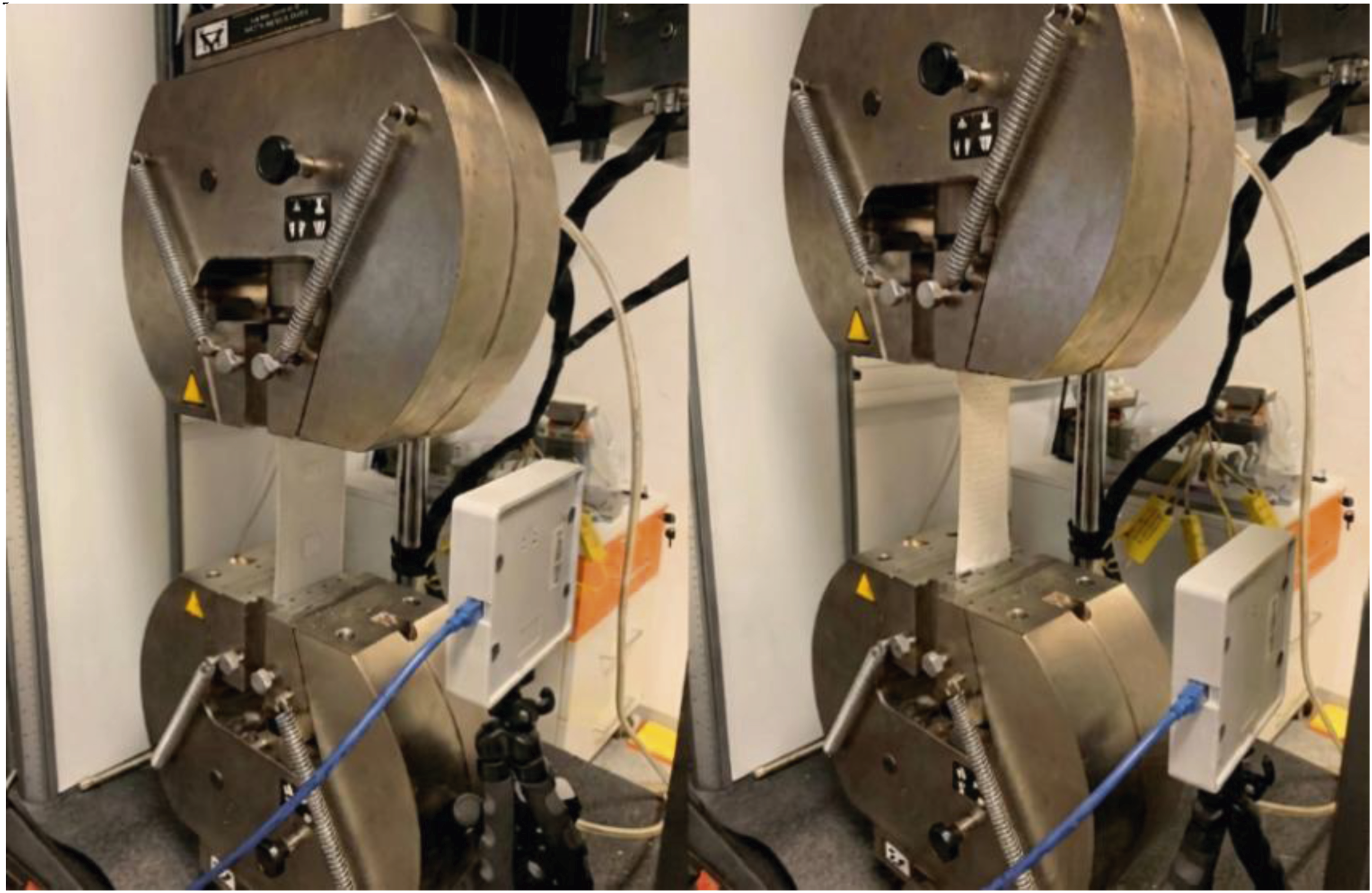
The experiment adopted a displacement-controlled quasi-static stepped loading mode with a loading rate set at 1 mm/min to simulate the stress conditions of a slowly pressurized gas cylinder. Loading was terminated once the tensile strain reached the upper limit preset in the simulation. The system utilized a synchronization strategy of “unified software triggering and post-hoc timestamp alignment,” simultaneously activating the testing machine controller, the strain gauge, and the reader monitoring terminal at the start of loading. The reader operated in Dense Reader Mode, returning data with millisecond-level timestamps via an Ethernet interface in real-time. To address the random fluctuations of RF signals in complex laboratory environments, the system continuously collected no fewer than 500 signal samples at each strain point and calculated their statistical mean. Background noise was effectively filtered out by eliminating anomalous outliers.
Although this study currently focuses on static pressure mapping, future dynamic monitoring can refer to methods for structural modal parameter identification and damage detection under ambient excitation. 33 By introducing more advanced state-recognition algorithms to perform a deep deconstruction of the fluctuation characteristics in the reflected signals, real-time health diagnosis of composite gas cylinders under complex dynamic loads can be achieved.
Analysis of experimental results
Summary mapping table of strain and signal strength for GFRP laminates.
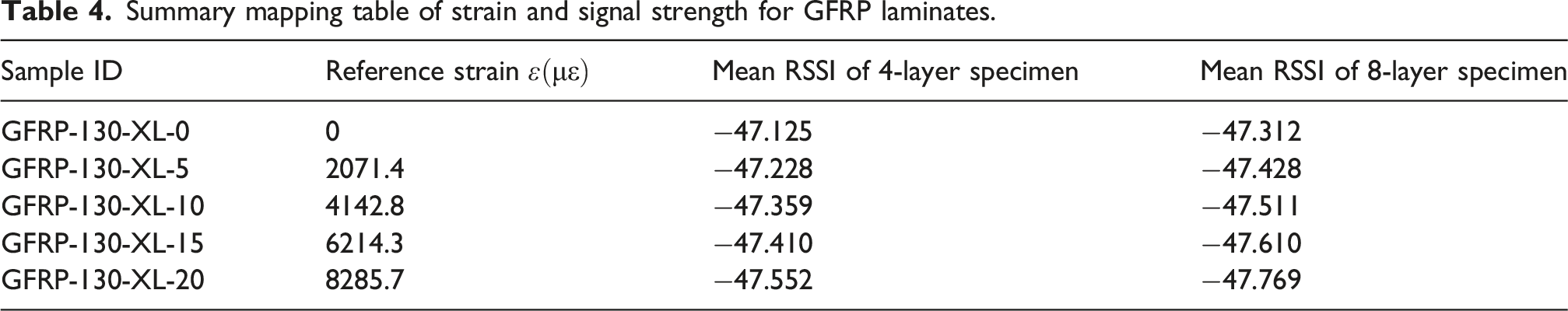
By comparing the simulation data presented above with the measured data in Table 3, it can be observed that both maintain high consistency in terms of magnitude and evolutionary trends. In the initial zero-strain state, the RSSI value of the 8-layer (8L) specimen is slightly lower than that of the 4-layer (4L) specimen, which validates the theoretical prediction mentioned earlier: an increase in dielectric thickness leads to greater dielectric loss of radio frequency (RF) energy. The least squares method was employed to perform a linear regression analysis on the experimental 915 MHz fixed-frequency RSSI data, the results of which are displayed in the fitting plots in Figure 11. The analysis reveals that for both the thin specimen (4L) and the thick specimen (8L), the evolution of reflected signal strength with mechanical strain exhibits a significant negative linear correlation (Figure 13). Fitting plot of RF signal intensity evolution versus reference strain for GFRP laminates. (a) Fitting curve of 4-layer layup specimens. (b) Fitting curve of 8-layer layup specimens.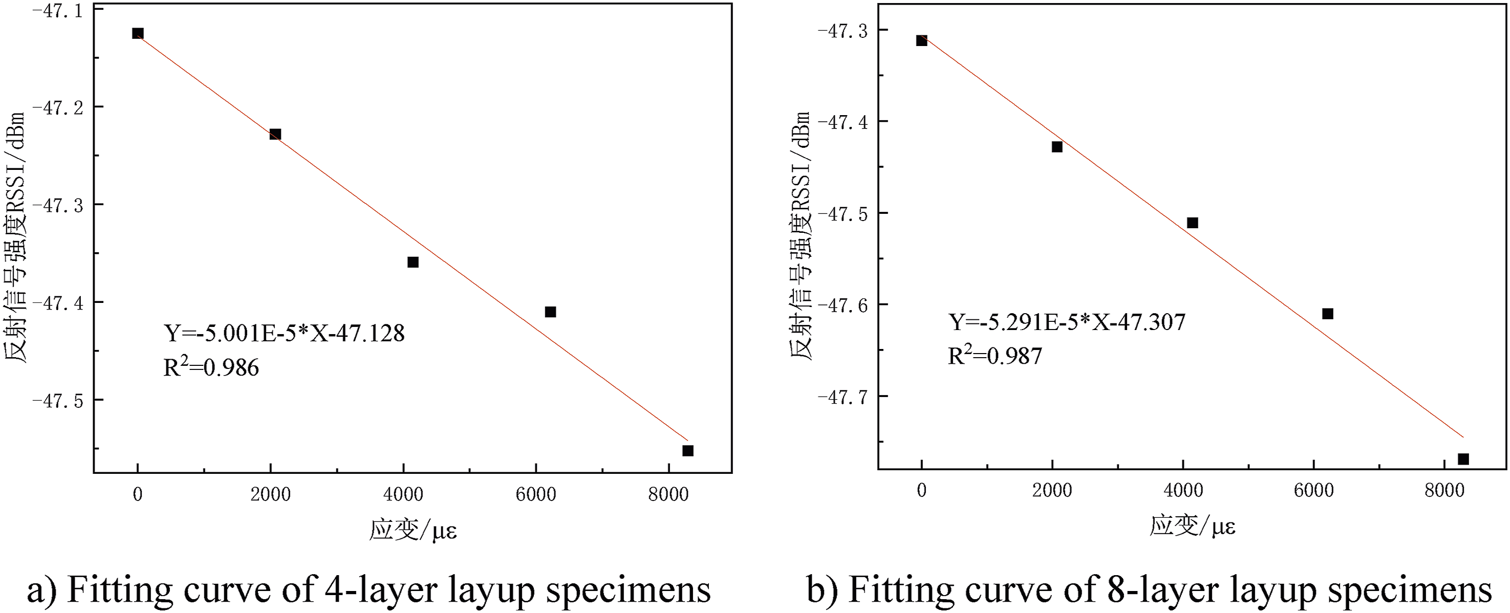
As shown in the figures, compared to the 4-layer (4L) specimen, the absolute value of the signal attenuation slope for the 8-layer (8L) specimen increases significantly. This indicates that in the surface-sensing mode, a thicker substrate exerts a stronger amplification effect on the impedance modulation caused by strain, thereby enhancing the monitoring sensitivity of the system. Although the study shows that increasing substrate thickness can significantly improve sensing sensitivity, a balance must be struck between the shear lag in mechanical transfer and the dielectric loss of electromagnetic waves. Experimental data suggest that an integrated thickness in the range of 1.0–1.5 mm (corresponding to 4L–8L ply stacks) represents the “golden window” for achieving high sensitivity and high-fidelity monitoring. If the thickness is increased further, the system may face the dual challenges of signal distortion and structural weight gain.
Additionally, it should be noted that the read distance significantly affects the system signal-to-noise ratio through the Friis Transmission Equation. In this experiment, the distance was fixed at 30 cm to ensure the initial signal strength (−47 dBm) was well above the reader’s detection threshold. Limited by the hardware signal resolution of 0.1 dB and combined with the fitted sensitivity of −48.705 dB/
Considering that the established simulation model is based on the typical wall thickness of a gas cylinder, while this section utilizes ultra-thin scaled specimens, a systematic bias exists between the two in terms of initial RSSI absolute values and absolute sensitivity (slope) due to dielectric scale effects. To eliminate the influence of dimensions and thickness gains, this study employs a normalization analysis method. The initial RSSI values for both simulation and experiment are calibrated as benchmark reference points, focusing on the incremental mapping trends of the signal as it changes with strain. Superimposing the normalized measured data onto the simulation curves reveals that the linear evolution trend of the measured RSSI relative to the benchmark strain exhibits extremely high consistency with the simulation prediction model. Specifically, the relative deviation between the sensitivity slope of the 4L specimen and the theoretical prediction is controlled within 6.47%. Meanwhile, the 8L specimen demonstrates a larger signal attenuation slope (with a deviation of approximately 12.64%), further confirming the enhancement effect of fringing field modulation caused by the increased dielectric substrate thickness. The primary reasons for these minor deviations can be summarized into the following two points:
Contact thermal resistance and adhesive layer effects
Despite using high-strength adhesives, the non-uniformity of the adhesive layer thickness during the manual attachment process may introduce slight initial impedance fluctuations, which are difficult to fully replicate in a purely idealized simulation model.
Multipath interference effects
Although layout precautions were taken, the metal hydraulic grips of the testing machine inevitably cause slight distortions in the far-field radiation pattern of the reader antenna, leading to a minor offset between the absolute RSSI values and the simulation.
Although this study currently relies on single-point resistance strain gauges as a benchmark for performance evaluation, future work could introduce Digital Image Correlation (DIC) technology to perform full-field strain characterization across the entire antenna attachment area. This would facilitate the quantitative verification of strain transfer uniformity between the antenna and the composite substrate, further confirming the integrity of the antenna-substrate coupling logic in the spatial dimension. Compared to traditional SHM technologies such as FBG or AE, the passive UHF RFID sensing logic employed in this method maintains linearity while significantly reducing system integration costs and wiring complexity. While FBG offers advantages in static measurement precision, the wireless and passive nature of this method—achieved through mechanical-electrical coupling—is better suited for the lifecycle management of large-scale distributed gas cylinder arrays, such as those found in hydrogen refueling stations.
Conclusion
This paper proposes and validates a wireless sensing method utilizing passive UHF RFID technology for monitoring the internal pressure of composite gas cylinders. The primary conclusions are as follows: 1. Established a complete mechanical-electrical mapping theoretical model. Analytical derivations and finite element simulations demonstrate that within the linear elastic range of 0–20 MPa, the surface strain of the cylinder body and the internal pressure satisfy a rigorous linear proportional relationship. 2. Revealed the physical mechanism of signal modulation. Mechanical strain induces a “redshift” in the resonant frequency by altering the electrical length of the antenna. At a fixed carrier frequency, this is converted into a monotonically attenuating RSSI signal. 3. Elucidated the impact of curvature on sensing characteristics. Through cylindrical cavity model analysis and HFSS simulations, it was found that curvature variations exert a systematic influence on tag gain and reading performance by altering the initial detuning state and electric field distribution. Specifically, the read range decreases as the cylinder radius increases. 4. Experimentally verified the reliability of the monitoring system. Experimental results from glass fiber reinforced polymer (GFRP) laminates show that the RSSI response possesses extremely high linearity and excellent sensitivity. Due to its wireless and passive advantages, this method is well-suited for large-scale distributed monitoring, such as in hydrogen refueling stations. Future work will focus on introducing DIC technology to verify full-field strain transfer and establishing full-scale 3D models including the domes to optimize monitoring accuracy in transition zones.
Footnotes
Funding
The authors disclosed receipt of the following financial support for the research, authorship, and/or publication of this article: Intelligent Wireless Detection Technology and In-service Health Monitoring Research for Plastic Liner Fiber-Wound Gas Cylinders; CQSJKJDW2024017.
Declaration of conflicting interests
The authors declared no potential conflicts of interest with respect to the research, authorship, and/or publication of this article.
Data Availability Statement
Data sharing not applicable to this article as no datasets were generated or analyzed during the current study.