
Abstract
This study develops a rapid and efficient microwave-assisted skin-integrated repair (MSIR) strategy for carbon fiber reinforced polymer (CFRP) laminates. The strategy synergizes a novel microwave curing process with an externally bonded prepreg skin design. Experimental results demonstrate that the optimized microwave curing achieves a near-full cure (99.9%) in merely 15 min, over 99% faster than conventional room-temperature vacuum-assisted resin infusion (VARI). Mechanistically, microwave volumetric heating enables rapid and uniform resin cross-linking within the repair zone, minimizing thermal gradients and ensuring robust interfacial bonding. Tensile tests show that the microwave-cured patch-only repair recovers 72.9% of the original strength, outperforming the VARI repair (68.5%). The incorporation of an external skin significantly enhances the repair efficiency to over 80%. A three-dimensional progressive damage finite element model, validated by experimental data (deviation <5.5%), elucidates the failure mechanisms: interfacial debonding dominates patch-only repairs, whereas the external skin acts as a load-sharing member that redistributes stress and shifts the failure mode from interface-driven debonding to synergistic tensile fracture of the parent laminate and the skin. Simulation-guided optimization of a full-length skin configuration predicts a repair efficiency of 92.6%, establishing the performance upper bound for this approach. This work provides a cohesive rapid-repair framework encompassing process, design, and predictive simulation for high-performance restoration of CFRP structures.
Keywords
Introduction
Carbon fiber reinforced polymer (CFRP) are extensively utilized in critical engineering fields such as aerospace,
1
advanced ships,
2
rail vehicles,
3
and pressure vessels,
4
owing to their exceptional specific strength and modulus, superior fatigue resistance, excellent electrical conductivity, and significant weight-saving potential.
5
However, CFRP components are threatened not only by transient impact events. Under prolonged service conditions involving complex environmental factors such as hydrothermal aging, ultraviolet exposure and cyclic mechanical loading, gradual damage accumulation occurs, including resin micro-cracking, fiber-matrix interfacial degradation, fiber fracture, and interlaminar delamination as shown in Figure 1. Such environmentally and mechanically driven damage, often subtle and slowly propagating, can lead to a severe degradation of residual stiffness and strength, posing a latent risk to structural integrity.7–9 Studies indicate that the prolonged exposure of such laminates to corrosive environments or hygrothermal conditioning, even under stresses significantly lower than their static strength, aggressively accelerates matrix plasticization and interfacial debonding, thereby considerably attenuating residual stiffness and strength and potentially leading to sudden catastrophic failure.10–12 Common damage types and repair methods for carbon fiber composites during service.
6
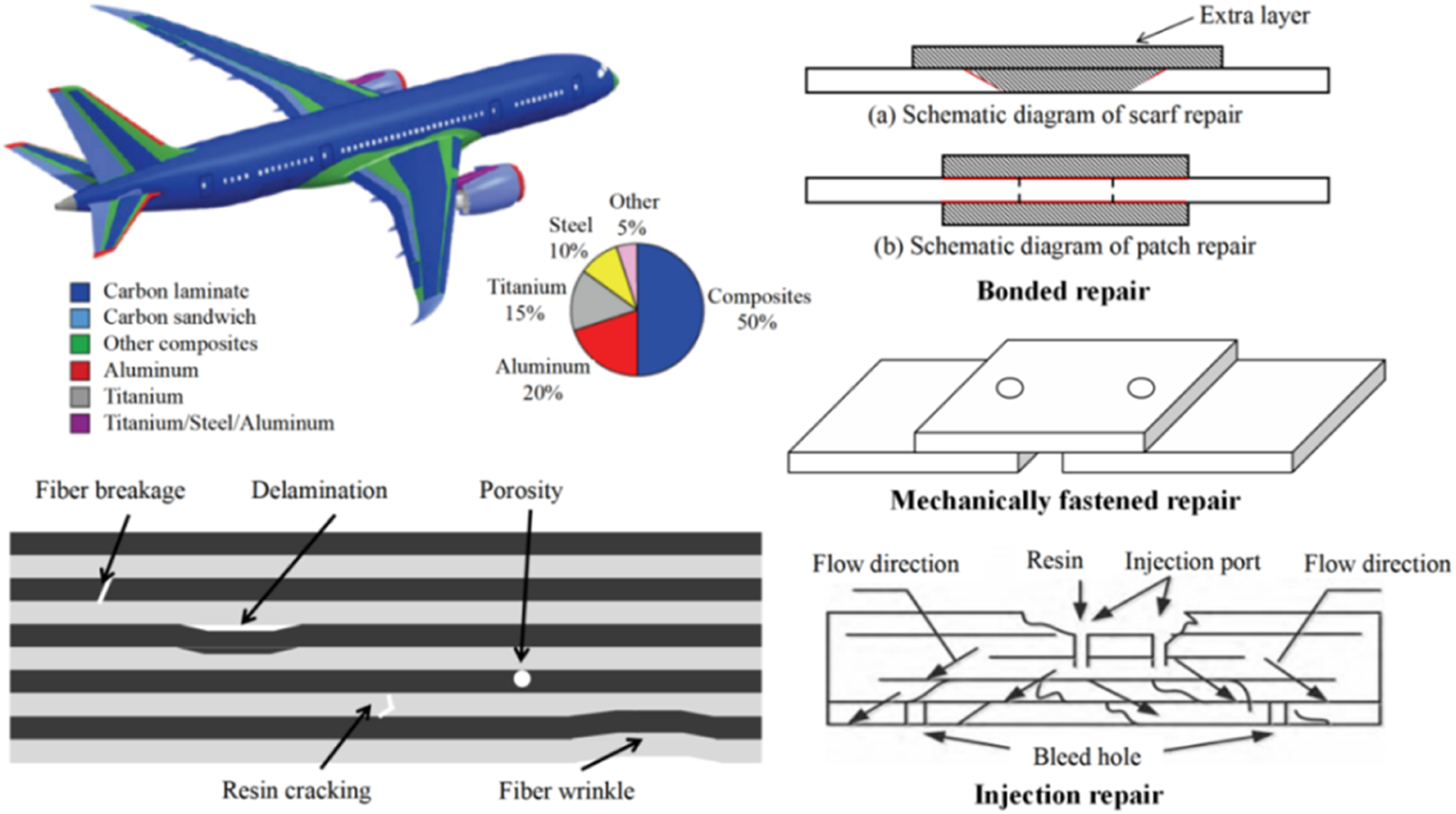
Extensive experimental and theoretical studies have been conducted on the repair of composite structures. Fundamental bonding repair mechanisms rely on load transfer from the damaged parent structure to the patch. However, their efficiency is often limited by interfacial debonding or stress concentration at patch terminations.13–15 To mitigate these issues, geometric configurations such as scarf and stepped lap joints have been extensively investigated, aiming to reduce peak shear stresses by increasing the bonded area. 16 Beyond geometric optimization, external reinforcement layers (skins) have emerged as an effective strategy: experimental studies demonstrate that applying additional prepreg layers over the repair zone significantly improves load transfer, achieving repair efficiencies exceeding 80%. 9 Finite element progressive damage analyses further confirm that such reinforcements suppress interfacial peeling and shift the failure mode from debonding dominated to tensile fracture of the composite laminate itself. 17 Quantitative assessments of repair efficiency based on residual strength and stiffness recovery ratios have also been established to provide a theoretical basis for repair optimization. 18 In terms of curing technology, conventional vacuum assisted resin infusion (VARI) and room temperature adhesive repairs require prolonged curing cycles, prompting recent research into rapid curing strategies. Techniques such as microwave and induction heating have been explored to achieve rapid resin cross linking while maintaining mechanical performance.19,20
Although existing repair strategies have partially restored structural load bearing capacity, significant limitations remain. Conventional VARI and room temperature adhesive repairs, despite their low cost, require curing cycles of 36–48 h, severely limiting maintenance efficiency and failing to meet the rapid response demands of aerospace and rail transportation. 21 While autoclave repairs achieve superior mechanical performance, they are constrained by equipment size and onsite accessibility, rendering them unsuitable for large scale or field repairs. Furthermore, most studies focus on patch only repairs, which are inherently limited by interfacial stress concentrations, with repair efficiencies often capped below 75%.9,14 Recent advances in rapid curing technologies have shortened processing times. However, balancing curing speed with interfacial bond strength and structural integrity remains a critical challenge.19,21
To address these challenges, this study proposes a microwave-assisted skin-integrated repair (MSIR) strategy. This approach innovatively integrates microwave volumetric heating with an externally cocured skin structure. The former utilizes dielectric loss and fiber conduction to achieve rapid and uniform resin crosslinking within the repair zone, 19 which could reduce curing time from tens of hours to merely several minutes. The latter alters the load transfer path through load sharing, shifting the failure mode from interfacial debonding to synergistic tensile fracture of the parent laminate and the skin, thereby overcoming the efficiency ceiling of patch only repairs. For carbon fiber components containing impact induced defects, a systematic repairability assessment and tailored repair protocol are prerequisites for practical application. This study experimentally characterizes the tensile performance of the repaired CFRP laminates and validates the results through finite element analysis, establishing a reliable simulation framework for predicting the mechanical behavior of repaired composite structures.
Experimental procedure
Materials and specifications
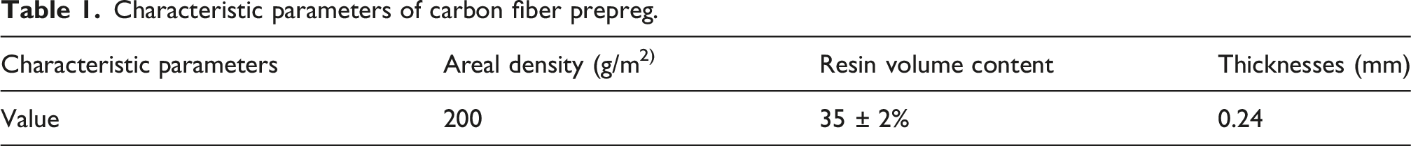
Characteristic parameters of carbon fiber prepreg.
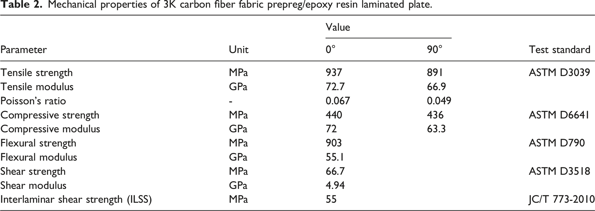
Mechanical properties of 3K carbon fiber fabric prepreg/epoxy resin laminated plate.
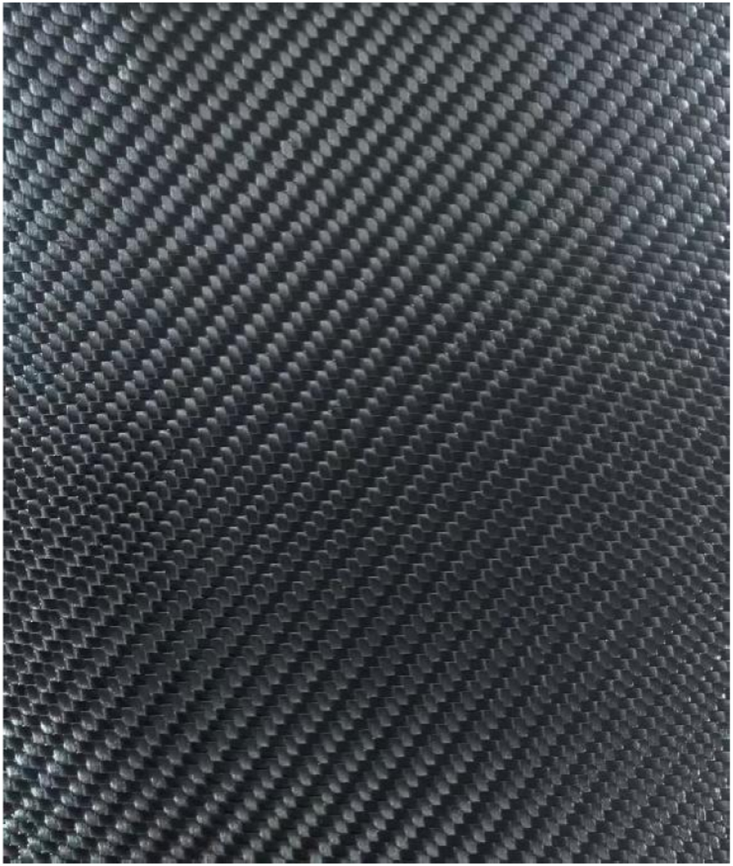
Surface morphology of the Carbon Fiber 3K Twill prepreg.
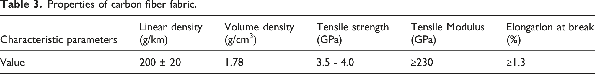
Properties of carbon fiber fabric.
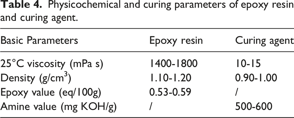
Physicochemical and curing parameters of epoxy resin and curing agent.
Samples preparation and damage simulation
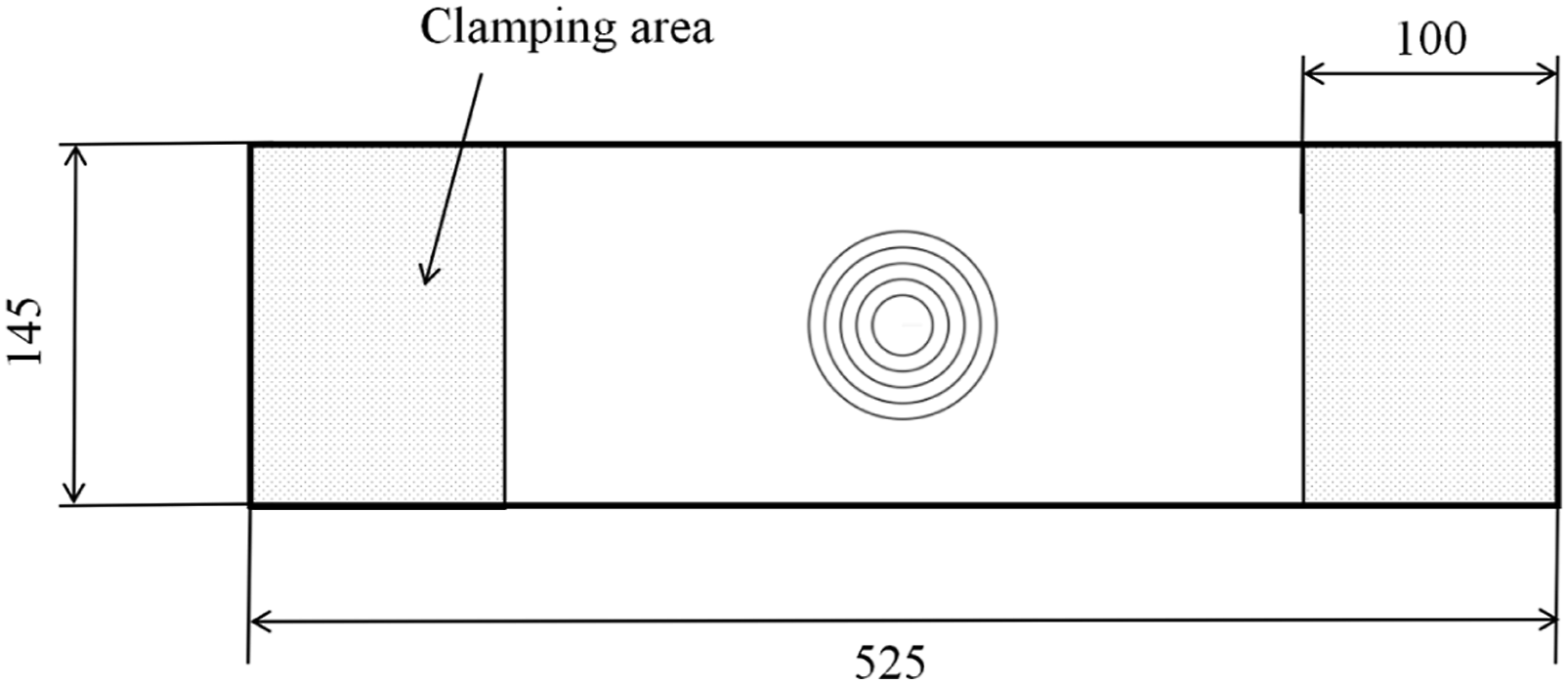
The parent laminates were manufactured via a vacuum-assisted hot-pressing process. Prepreg sheets (550 mm × 500 mm) were laid up in a mold between aluminum plates. The assembly was vacuum-bagged and cured in an oven under a vacuum of −0.1 MPa. The curing cycle consisted of a 1-h dwell at 80°C, followed by a 2-h dwell at 130°C, with a total cycle time of 4 h. After natural cooling to room temperature, the panels were demolded, inspected, and trimmed to the final dimensions of 525 mm × 145 mm×2.4 mm.
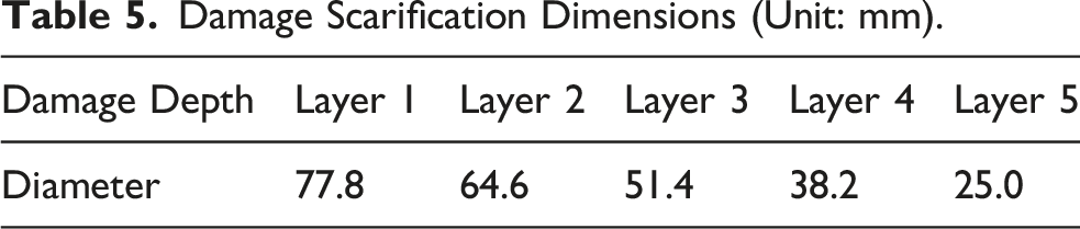
Damage Scarification Dimensions (Unit: mm).
Schematic of the tapered damage zone simulating shallow impact damage (BVID) in CFRP laminates.
Microwave repair equipment
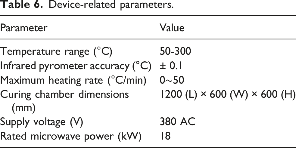
Device-related parameters.
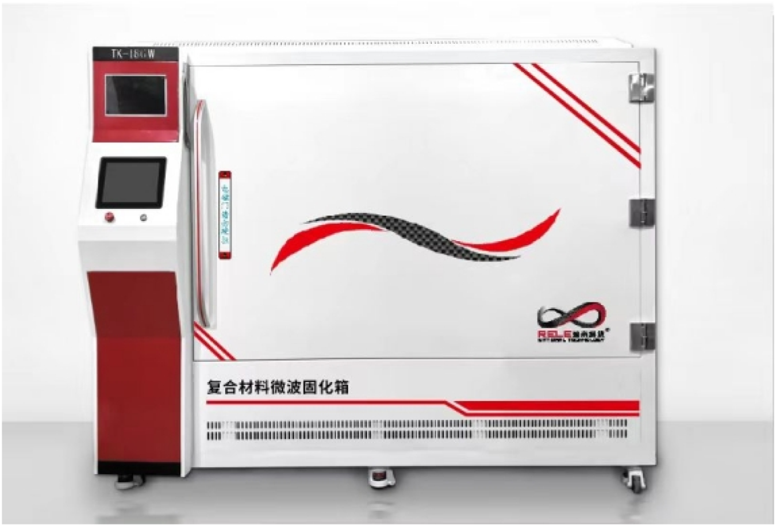
Microwave curing furnace.
The system implements a “temperature platform control”strategy. This is a closed-loop, multi-stage thermal regulation protocol designed for precise energy management during the initial curing phase. It involves defining specific temperature setpoints and corresponding dwell times. System power (magnetron output and duty cycle) is automatically modulated based on real-time surface temperature feedback from an infrared pyrometer to maintain the target temperature profiles. This approach optimizes curing kinetics while mitigating the risk of thermal runaway common in microwave processing.
It should be noted that the microwave curing system employed in this study was designed with onsite repair applications in mind. The system features a box type cavity with a lift up door, facilitating the placement and removal of large or assembled composite structures for in-situ processing. Furthermore, the microwave field distribution was optimized to achieve localized heating, minimizing thermal effects on non-target areas. Although the current prototype is primarily utilized in a laboratory setting to validate the feasibility and mechanisms of microwave repair, its accessible configuration, localized heating capability, and compact design philosophy lay the groundwork for the future development of portable microwave repair equipment suitable for field maintenance.
Microwave curing repair procedure
Two distinct patch repair schemes were designed and implemented for the STR specimens:
Scheme 1. (Tapered Patch Repair): Circular prepreg patches, each 0.24 mm thick, were placed layer-by-layer into the ground damage zone. The diameter of each patch corresponded to the grinding dimensions listed in Table 5, creating a tapered repair stack.
Scheme 2. (Stepped Scarf with External Reinforcement): This scheme built upon Scheme 1 by adding one or two external, rectangular prepreg reinforcement plies on the repair side. These plies had a width of 145 mm and lengths of 155.6 mm (2× the outermost damage diameter) and 233.4 mm (3×the diameter), respectively.
Schematic cross-sections illustrating the two repair schemes and their lay-up are presented in Figure 5. Schematic diagram of repaired section and lay-up angle:(a)Scheme 1 (Tapered Patch Repair), (b) and (c) Scheme 2 (Stepped Scarf with External Reinforcement).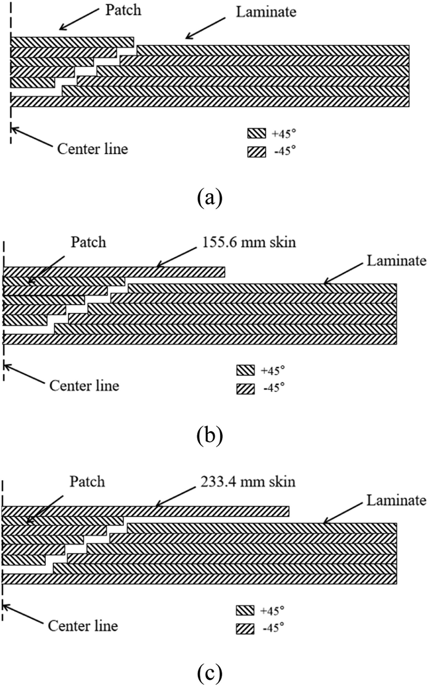
For microwave curing, the repaired specimen was placed on a silicon carbide mold for uniform heat conduction, vacuum-bagged, and sealed. The curing cycle, detailed in Figure 6, was executed in the microwave oven: ramp to 75°C in 3 min (1000W), dwell at 75°C for 3 min (1000W), ramp to 120°C in 3 min (1000W), and final dwell at 120°C for 6 min (1000W), resulting in a total cycle time of 15 min. Post-curing, samples were cooled to room temperature and lightly sanded with 240-grit paper. Microwave curing process curve.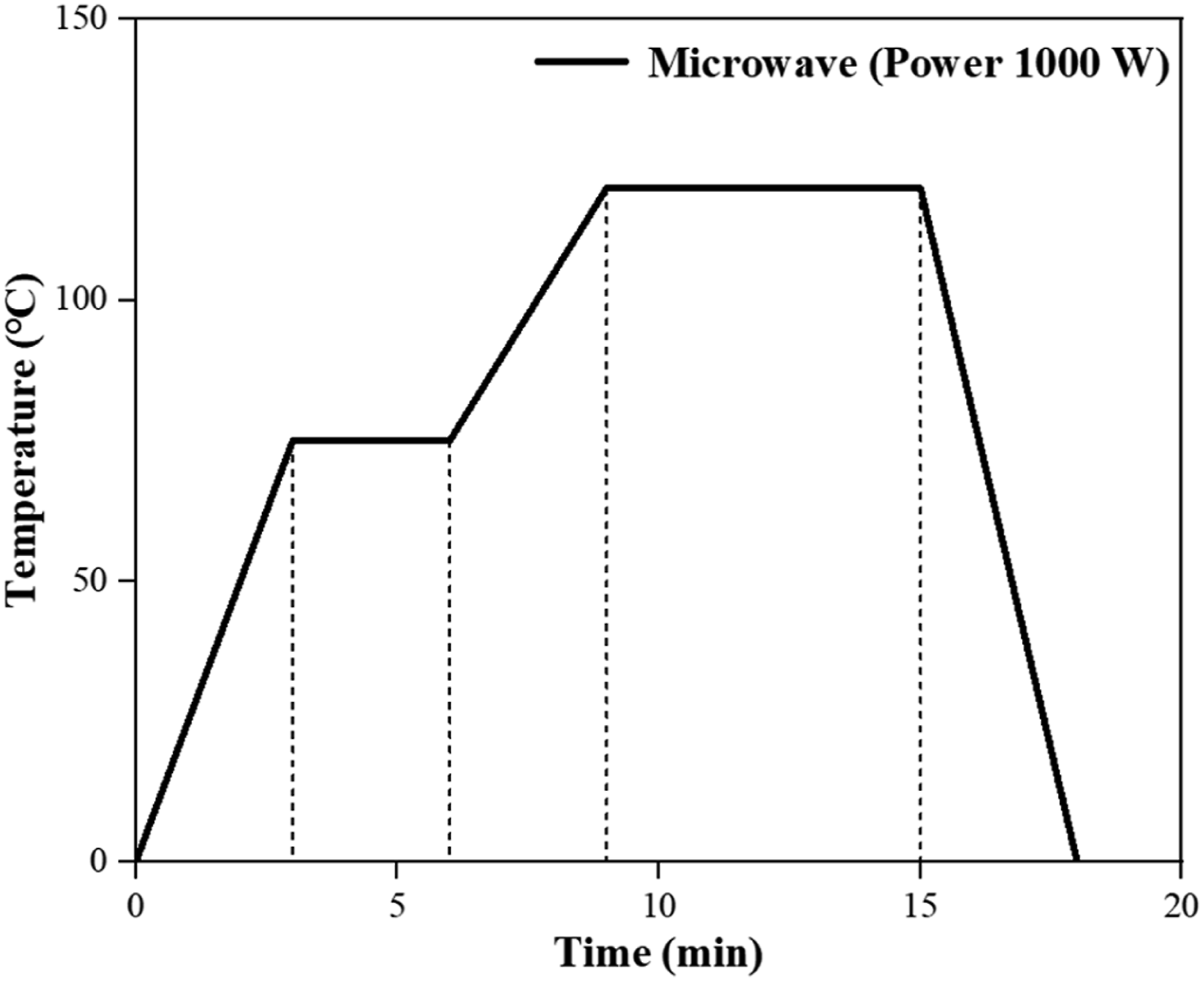
To visually evaluate the restoration quality, Figure 7 presents the surface topography of the specimens before and after repair. Figure 7(a) shows the step-drilled damage region, characterized by a distinct conical hole with exposed fibers. After curing, Figure 7(b) demonstrates that the tapered patch achieved a relatively smooth surface with good resin wetting, showing continuous texture with the substrate. Notably, Figure 7(c) and 7(d) reveal that the addition of the external skin (Scheme 2) resulted in a more uniform surface finish and better load transfer continuity, as indicated by the consistent glossy appearance across the repair zone and the surrounding structure. No obvious voids or delamination were observed on the surface of any repaired specimens. Surface topography of repaired specimens: (a) grinding area (damaged state), (b) tapered patch repair (Scheme 1), (c) patch +155.6 mm skin (Scheme 2), and (d) patch +233.4 mm skin (Scheme 2).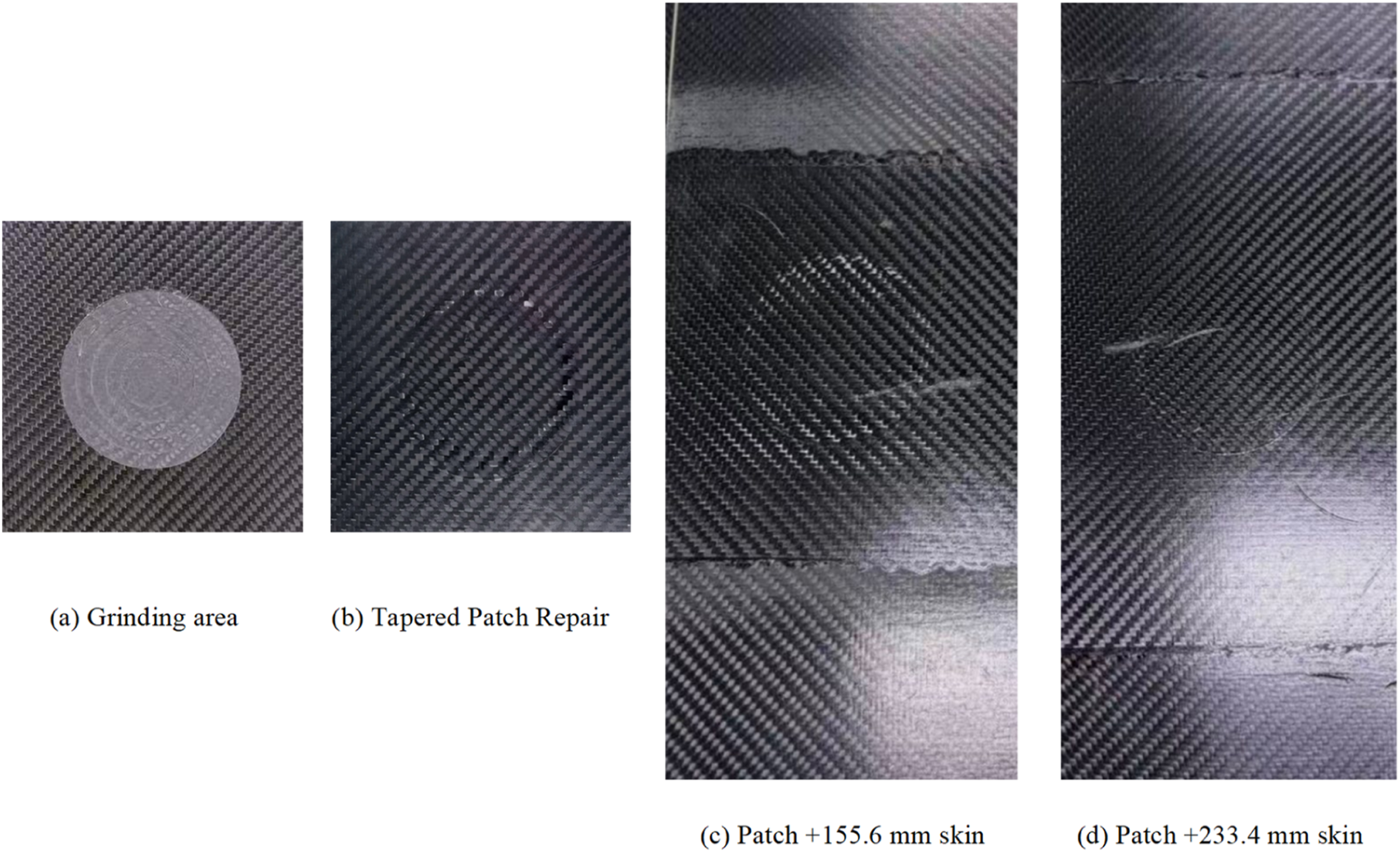
Conventional VARI repair procedure
As a benchmark, damaged specimens were also repaired using the conventional Vacuum-Assisted Resin Infusion (VARI) technique. Dry carbon fiber fabric patches, cut to match the ground areas, were stacked into the damage zone. A resin mixture (epoxy resin to hardener weight ratio of 100:30) was infused under vacuum. Curing was conducted at ambient outdoor conditions (∼25°C) for 36-48 h, followed by surface finishing. A comparison of the processing times for the two techniques is shown in Figure 8. Comparison of processing Times for two repair techniques.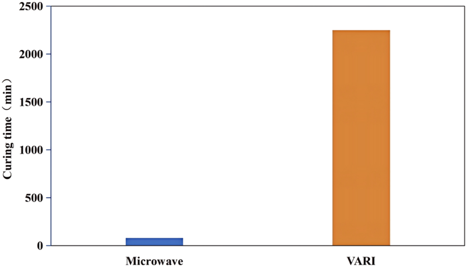
Curing degree characterization
The degree of curing was analyzed using a German Netzsch 204F1 differential scanning calorimeter (DSC). By measuring and analyzing the exothermic curves of completely uncured samples and samples cured using microwave curing process parameters, the degree of curing for each samples was determined. The specific calculation is shown in equation (1).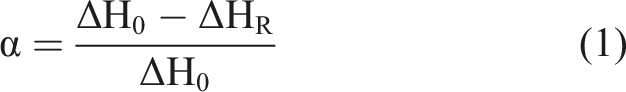
This method allows for precise quantification of the curing process by analyzing the thermodynamic characteristics of both the uncured and cured states. The DSC results provide a clear indication of the extent of cross-linking achieved during the curing process, thereby ensuring accurate assessment of the mechanical properties of the repaired composite materials.
Tensile test of repaired specimens
Tensile tests were carried out on composite laminate specimens that underwent microwave curing repair according to different schemes. The testing instrument was the SUNS 100T electronic universal testing machine. Tensile tests followed ASTM D3039/D3039M-2017 with a tensile rate of 2 mm/min. The clamping area at both ends of each specimen was set to 145 mm × 100 mm. To prevent sample shifting or twisting during the stretching process, high-density sandpaper was added between the fixture and the sample to increase friction, thereby ensuring test accuracy.
Finite element method for repair of composite laminates
Progressive damage model
Commonly used failure stress criteria include maximum principal stress failure criterion, Hashin failure criterion, Hoffman failure criterion, Tsai Wu tensor theory, and Tsai Hill failure criterion. 22 For composite material bonding repair, the Hashin failure criterion is chosen for failure analysis due to its simplicity in programming and its ability to accurately predict the ultimate bearing capacity of composite laminates after bonding repair. The specific formula for Hashin failure criterion are as follows:
Fiber Tensile Failure (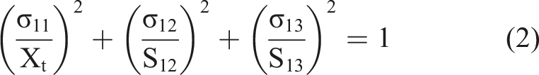
Fiber compression failure (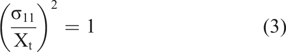
Matrix tensile failure (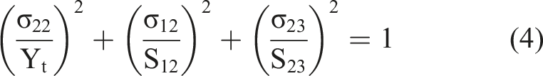
Matrix compression failure (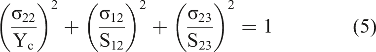
Fiber matrix shear failure (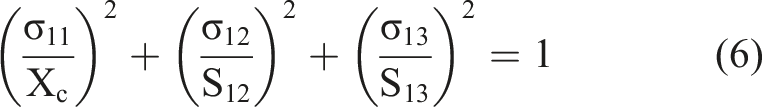
According to the Hashin failure criterion mentioned above, as the stresses in various directions of the laminate board gradually increase, damage occurs at internal integration point. Consequently, material property parameters are reduced, leading to an inability of the initial elastic matrix to accurately predict changes. Therefore, it is necessary to introduce a stiffness degradation model to determine the failure mode of each element and correct the basic parameters of the material.
It should be noted that the mechanical behavior of the fiber-resin interface within the composite laminate is not explicitly modeled using discrete cohesive elements. Instead, it is effectively represented by the combination of the Hashin failure criteria and the stiffness degradation model. When the stress components in the fiber direction (σ11) or transverse direction (σ22) exceed the corresponding strength thresholds, failure is identified via equations (2)–(6). Subsequently, the material properties are degraded by reducing the elastic moduli (E11, E22) and shear moduli (G12, G23), thereby simulating the macroscopic response of interfacial debonding and matrix cracking. This continuum damage mechanics (CDM) approach avoids computationally expensive micro-modeling while accurately capturing damage initiation and propagation within the composite.
Adhesive layer cohesion model
When subjected to displacement loads, the adhesive layer between the substrate and the patch will fail due to exceeding its strength limit, Therefore, accurately simulating the mechanical properties of the adhesive layer is particularly important for model analysis. In this study, an cohesive force model was used to simulate the behavior of the adhesive layer between the plywood substrate and the patch. The ABAQUS software provided a cohesive element with a bilinear constitutive relationship, and the specific expression of the constitutive relationship is as follows: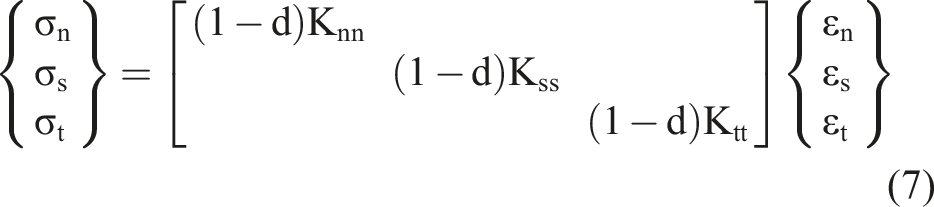
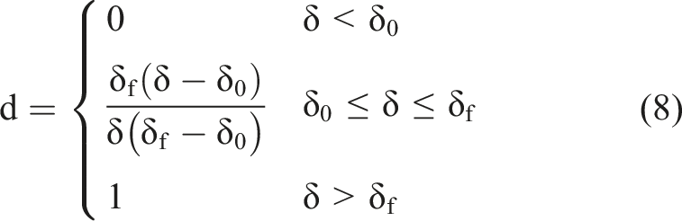
In the formula: 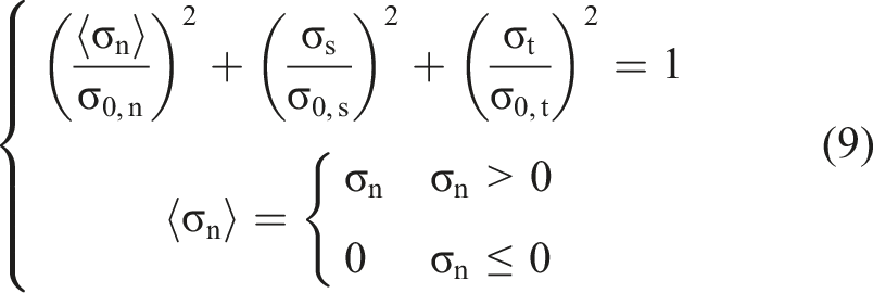
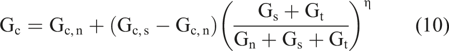
The energy based B-K criterion is chosen as the damage propagation criterion, and its expression is as follows:
23
Composite finite element model
Numerical simulations were conducted using ABAQUS to investigate the mechanical behavior of CFRP laminates subjected to damage and subsequent repairs. To balance computational accuracy with efficiency during the tensile simulation, an adaptive mesh refinement strategy was employed. The repair zone was discretized using a finer mesh (with an approximate element size of 2 mm), while the mesh density was gradually coarsened outward (transitioning from 2 mm to 5 mm). This approach significantly improved computational efficiency compared to a uniformly refined mesh. The CFRP laminate model was constructed using structured hexahedral elements (C3D8R), comprising 16,460 elements and 18,887 nodes. For boundary conditions, one end of the laminate was fully constrained to represent the clamped condition, while a displacement load was applied at the opposite end to simulate tensile testing. The finite element model configuration and boundary conditions are illustrated in Figure 9. Finite element model of laminate (a) Repair patch mesh (b) Overall mesh structure.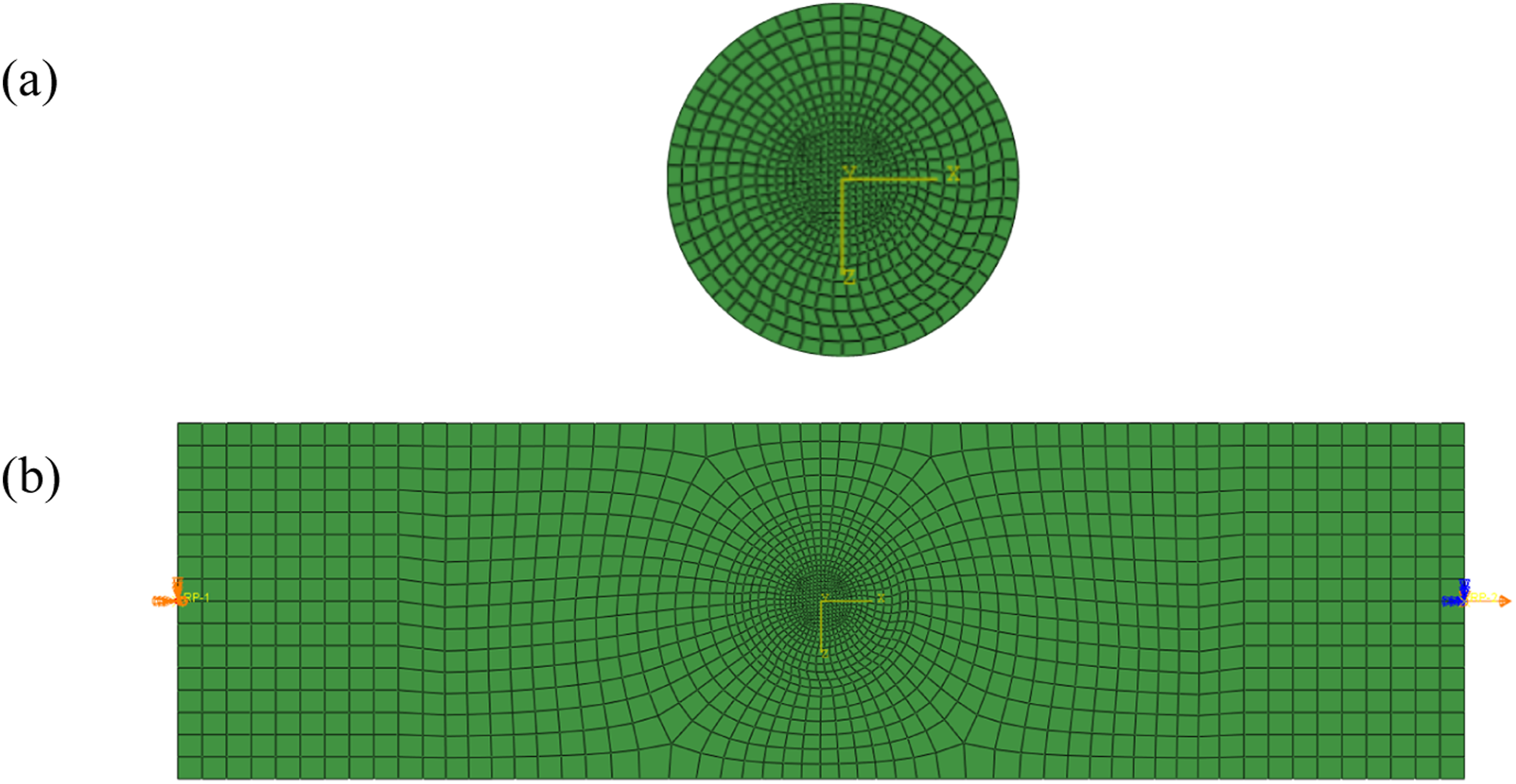
Results and discussion
Microwave curing mechanism and degree of cure
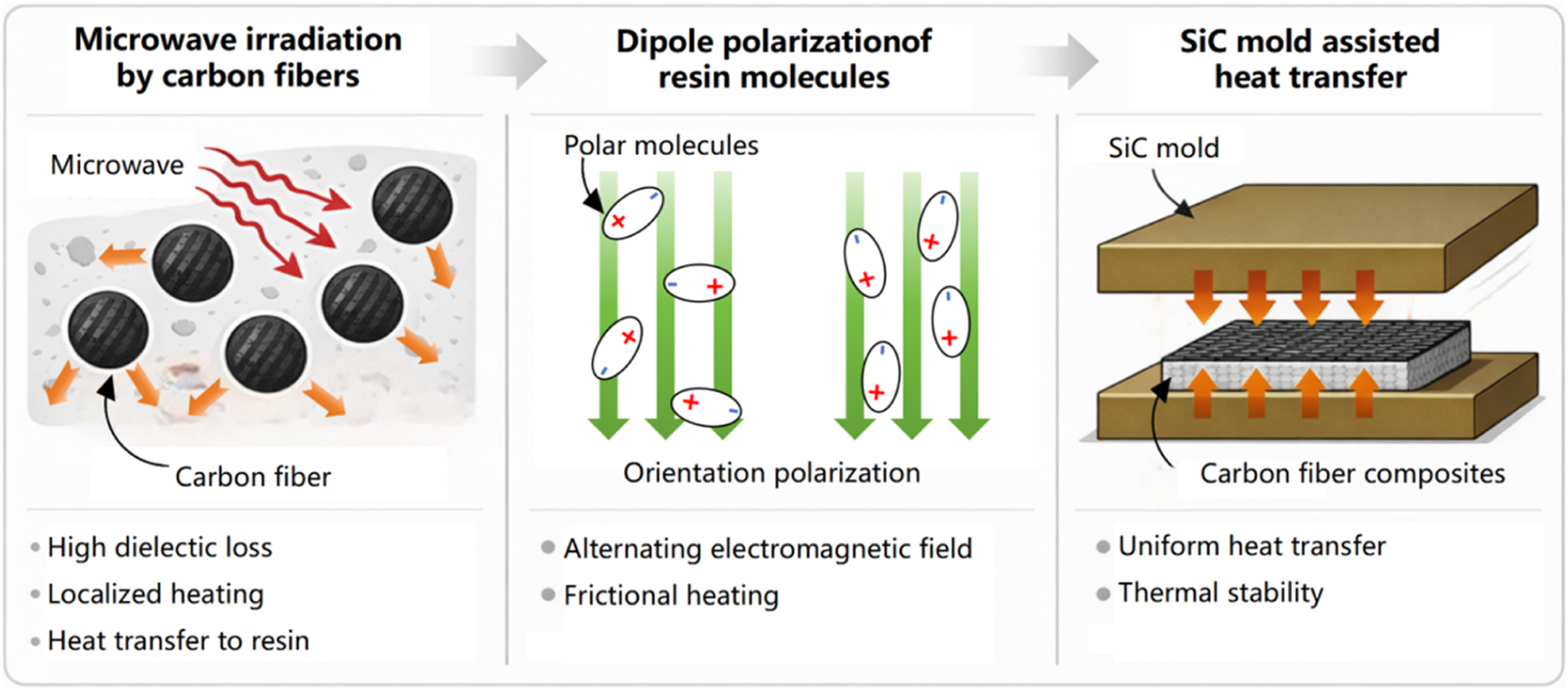
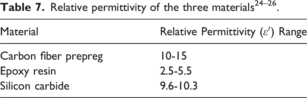
Microwave curing represents a fundamentally different approach from conventional thermal curing, which relies on external conductive or convective heating. The enhanced efficiency of microwave curing for carbon fiber composites can be attributed to a synergistic effect of three primary heating mechanisms, as illustrated in Figure 10. (1) (2) (3) Schematic diagram of microwave curing mechanism.
The efficacy of the optimized microwave curing cycle (Figure 5) was quantitatively assessed via Differential Scanning Calorimetry (DSC). The DSC thermograms for both microwave-cured and VARI-cured samples are shown in Figure 11. The residual heat of reaction (ΔHR) for the microwave-cured specimen was measured to be 0.134 J/g. Using equation (1), this corresponds to a degree of cure (α) of 99.9%. In contrast, the VARI-cured specimen achieved a degree of cure of 98.0%. Both values exceed the threshold of 95% typically considered indicative of full cure for structural composites.
21
DSC curing curve of samples.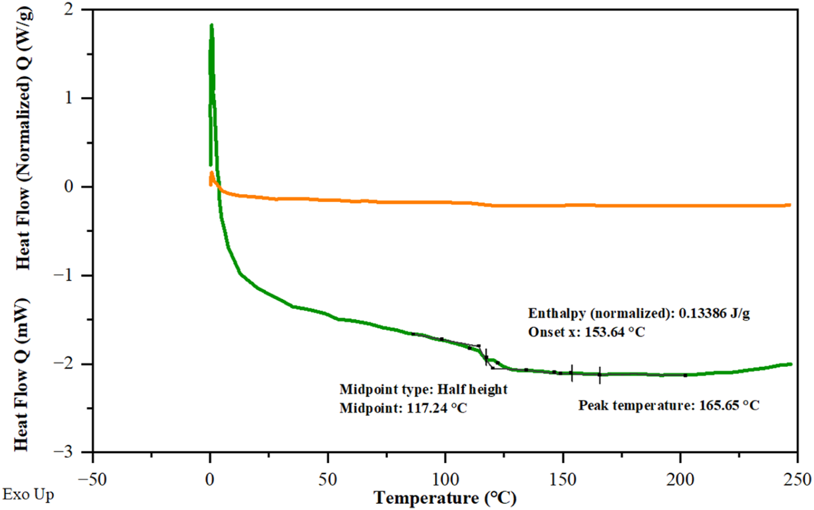
The most striking advantage of microwave curing is the dramatic reduction in processing time. The complete microwave cure cycle was accomplished in 15 min, compared to 36-48 h required for room-temperature VARI curing,a reduction exceeding 99% in active processing time. This exceptional efficiency translates directly into lower energy consumption, reduced manufacturing costs, and the potential for rapid, on-demand repair, significantly enhancing the practicality and economic viability of CFRP applications.
Tensile performance of repaired laminates
Repair Scheme 1 (Tapered patch only)
Summarizes the mechanical performance test results for composite laminates.
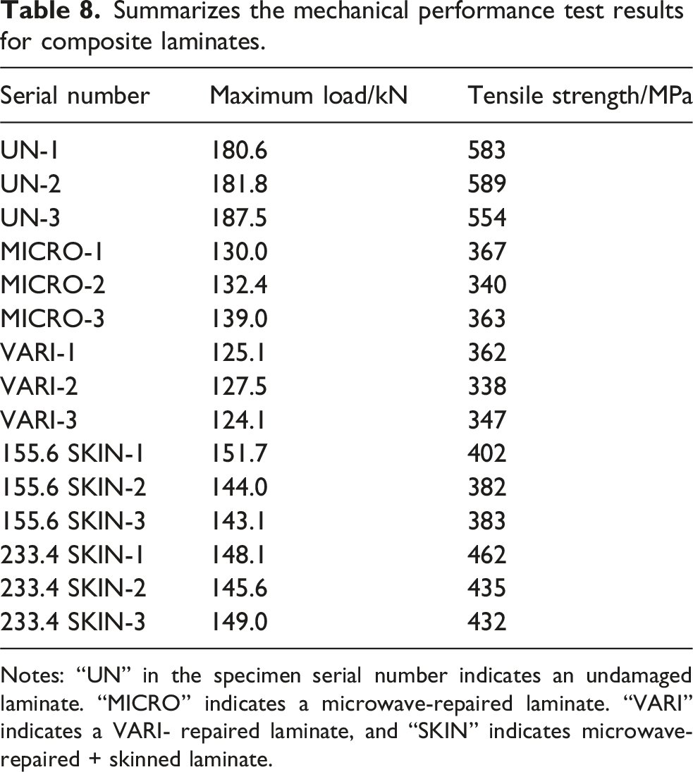
Notes: “UN” in the specimen serial number indicates an undamaged laminate. “MICRO” indicates a microwave-repaired laminate. “VARI” indicates a VARI- repaired laminate, and “SKIN” indicates microwave-repaired + skinned laminate.
Laminate specimens test results.
Repair Scheme 2 (Tapered patch with external skin)
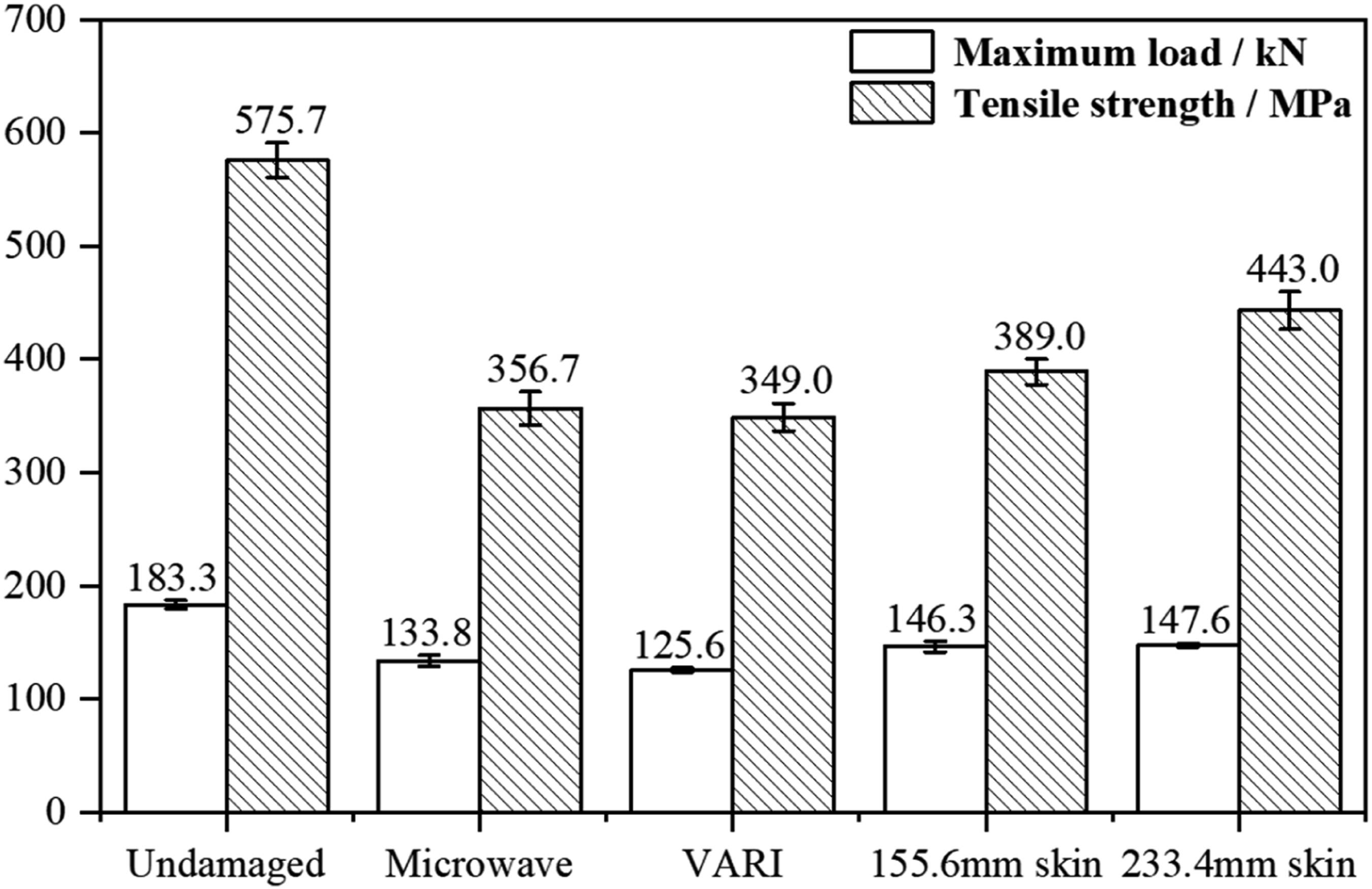
The performance of repaired laminates was substantially improved by incorporating an external, co-cured prepreg skin over the patched region. This design modification transforms the repair from a localized patch to a structurally integrated, load-sharing system. As shown in Figure 12, the application of a 155.6 mm long skin increased the average ultimate load to 146.3 kN (repair efficiency: 79.8%), while a 233.4 mm skin further enhanced the performance to 147.6 kN (repair efficiency: 80.5%). The tensile strength also showed a clear positive correlation with skin size, increasing from 356.7 MPa (patch-only) to 389.0 MPa and 443.0 MPa for the 155.6 mm and 233.4 mm skins, respectively.
This finding is consistent with previous reports, in which external reinforcement layers have been demonstrated to effectively enhance load-transfer efficiency in repair structures. 16 The improved reinforcement performance observed in the present study can be attributed to two synergistic mechanisms enabled by microwave-assisted skin repair.
Improved Load Transfer and Stress Redistribution: The external skin acts as a primary load path, bridging the repaired zone and efficiently transferring tensile stress around the damage. This reduces the stress concentration at the critical patch/parent laminate interface, which is the typical initiation site for failure in patch-only repairs. The finite element simulations confirmed that the presence of the skin significantly lowered the peak stresses in this region, delaying the onset of interfacial debonding.
Superior Laminate Quality via Controlled Microwave Curing: The microwave curing process, particularly the implemented “temperature platform control” strategy, is critical for the success of the skin repair. The volumetric “body heating” ensures simultaneous and uniform curing through the entire thickness of the layered repair stack (patch + skin), minimizing thermal gradients that can induce residual stresses or incomplete curing at interfaces. Furthermore, the controlled heating rate moderates the resin’s initial exothermic reaction, suppressing the formation and expansion of voids and microcracks within the adhesive layer and the composite plies. This results in a repair zone with higher structural integrity and more consistent mechanical properties. The “temperature plateau control” strategy has been proven to be an effective method for optimizing the microwave curing process and obtaining superior material properties. 19
A comprehensive comparison of the repair mechanisms and tensile performance between Scheme 1 (patch only) and Scheme 2 (patch + skin) reveals fundamental differences in failure modes. Scheme 1 is dominated by interfacial debonding at the repair boundary, leading to premature load transfer interruption and a limited repair efficiency of 72.9%. In contrast, the externally cocured skin in Scheme 2 acts as a load sharing member, effectively suppressing peel and shear stress concentrations at the termination of the patch. This shifts the failure mode from interfacial debonding to synergistic tensile fracture of the parent laminate and the skin. This mechanistic transition elevates the repair efficiency to 80.5% for the 233.4 mm skin configuration and significantly enhances the nonlinear deformation capacity. These results demonstrate that altering the load transfer path through structural design is an effective strategy to overcome the efficiency ceiling of patch only repairs.
Finite element simulation and damage progression analysis
Model validation
The developed progressive damage finite element model demonstrated high predictive accuracy. As illustrated in Figure 13, the simulated load-displacement curves for all three repair configurations (patch-only, 155.6 mm skin, 233.4 mm skin) showed excellent agreement with experimental data, both in terms of initial stiffness, nonlinear progression, and ultimate load. The predicted ultimate loads deviated by less than 5.5% from the experimental averages,
15
validating the constitutive models (cohesive zone model for interlaminar failure and continuum damage mechanics for intralaminar failure) and the assigned material parameters. This close correlation confirms the model’s reliability as a tool for analyzing failure mechanisms and for the exploratory design optimization presented in the following section. Comparison of experimental and simulated load-displacement curves for (a) patch-only repair, (b) repair with 155.6 mm skin, and (c) repair with 233.4 mm skin.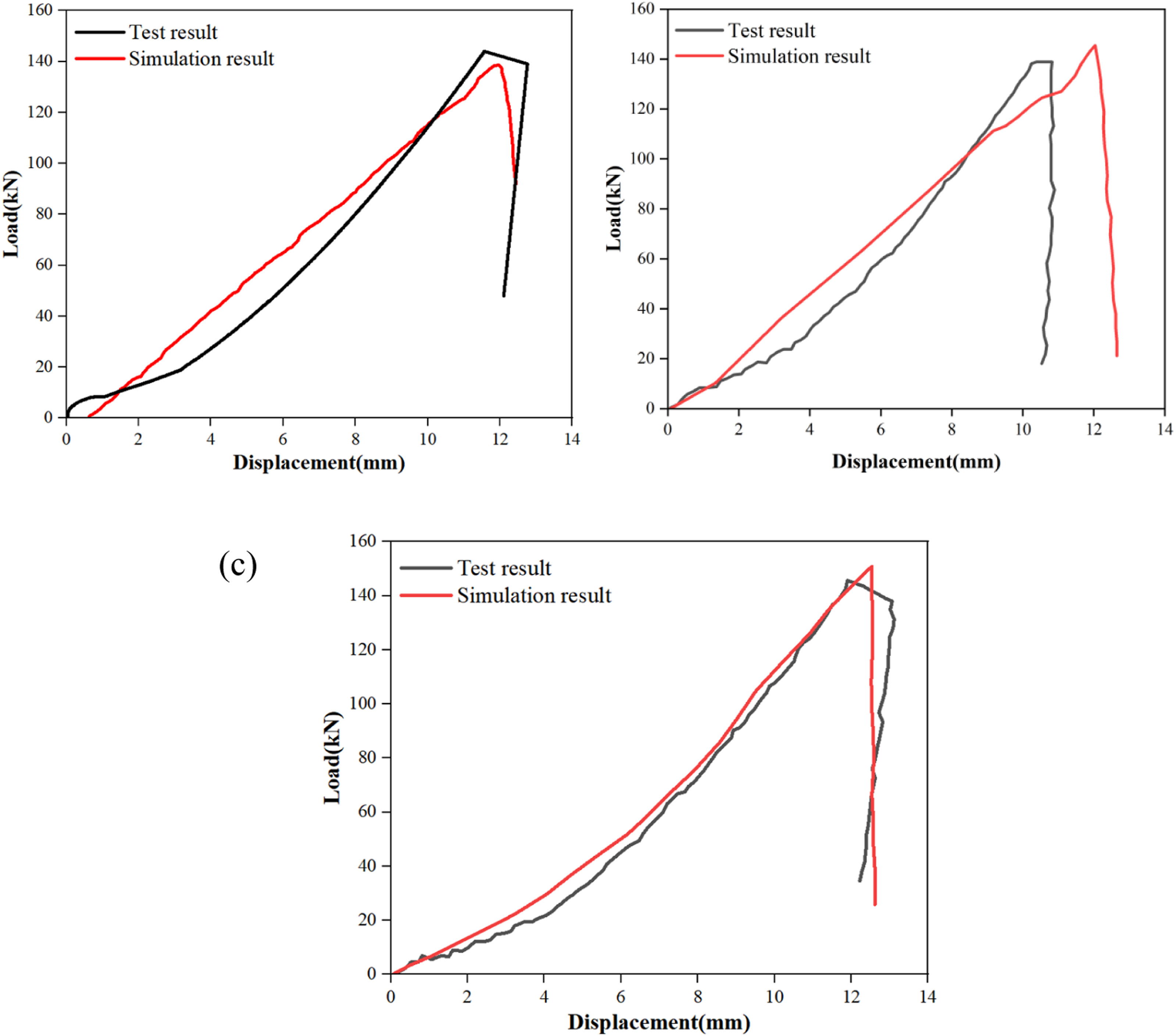
As a baseline, the undamaged specimen was also simulated. The simulated failure mode aligned well with the experimental results. Figure 14 provides a direct comparison, showcasing the tensile fracture morphology of the undamaged laminate from both the test and the simulation. The specimen exhibited a clear, smooth fracture surface, a characteristic brittle failure mode resulting from its structural integrity and uniform stress distribution, which the simulation accurately reproduced. Fracture mode comparison: (a) experimental result of the undamaged specimen after tensile test, (b) corresponding simulation result.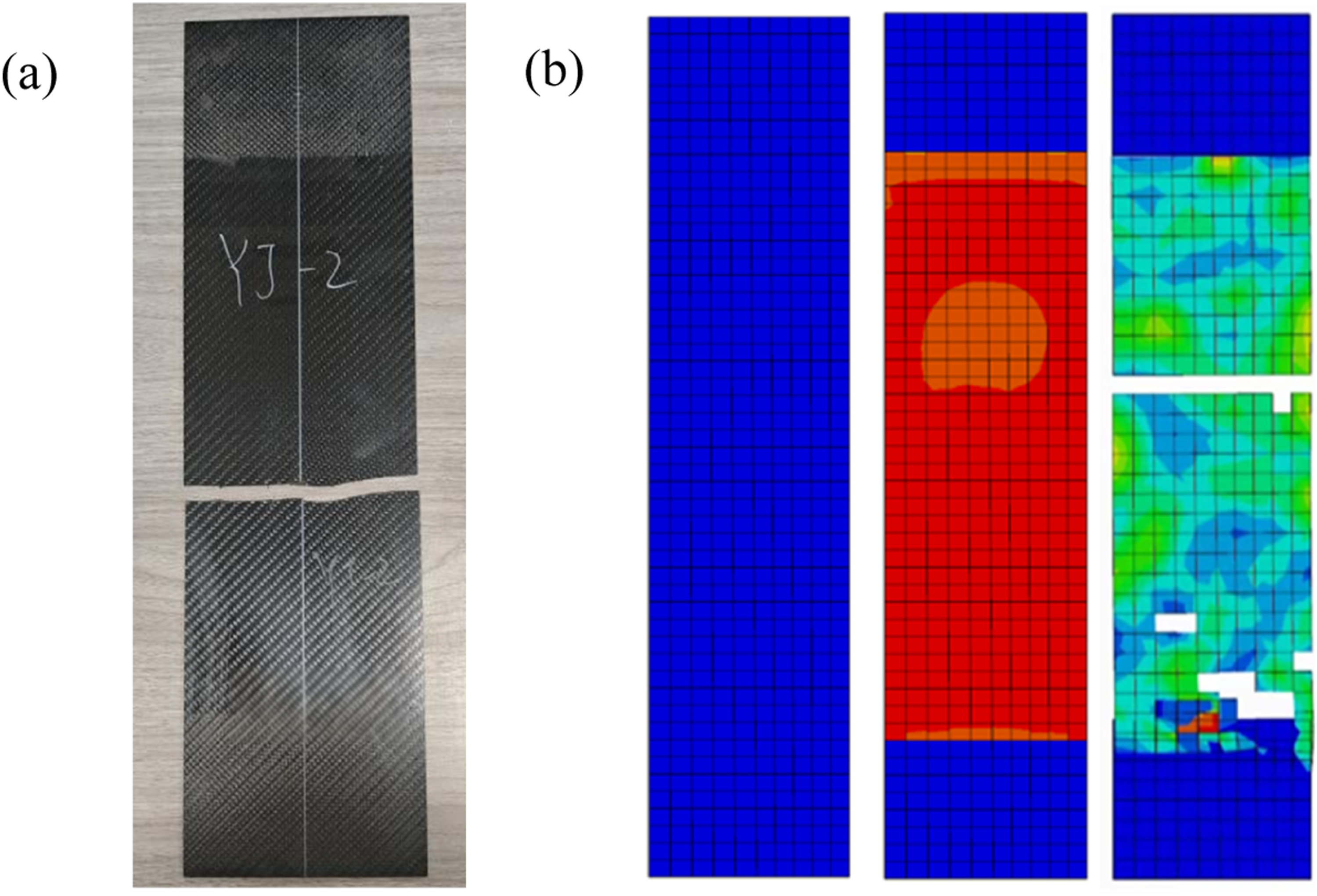
Failure analysis of patch-only repaired laminates (Scheme 1)
Correlation between microwave repair test results and simulation predictions.
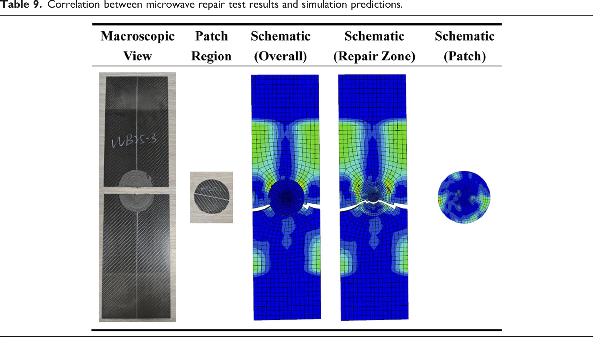
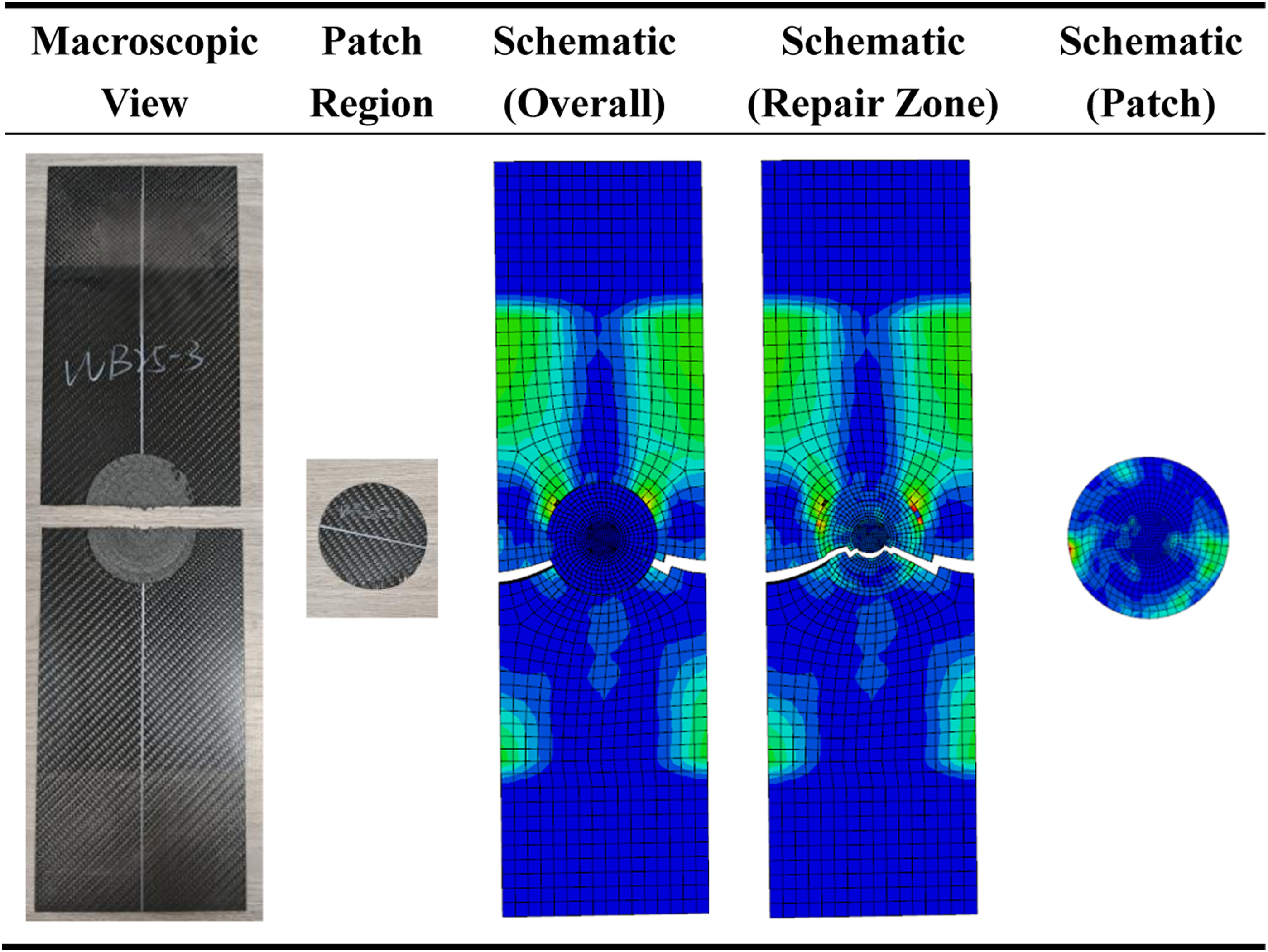
The stress analysis under tensile loading revealed a complex stress state. Regions distal to the repair exhibited relatively uniform stress distributions. In stark contrast, the vicinity of the repair was characterized by significant stress concentrations. The maximum principal stress was localized within a band aligned with the loading direction, while the minimum stress appeared in a perpendicular band at the center of the parent plate. This pronounced stress gradient indicated suboptimal load transfer, identifying the patch periphery and the parent laminate’s drilled region as the critical stress zones. This failure mode is consistent with the widely recognized understanding that interfacial debonding is the primary weakness in patch repair. 14
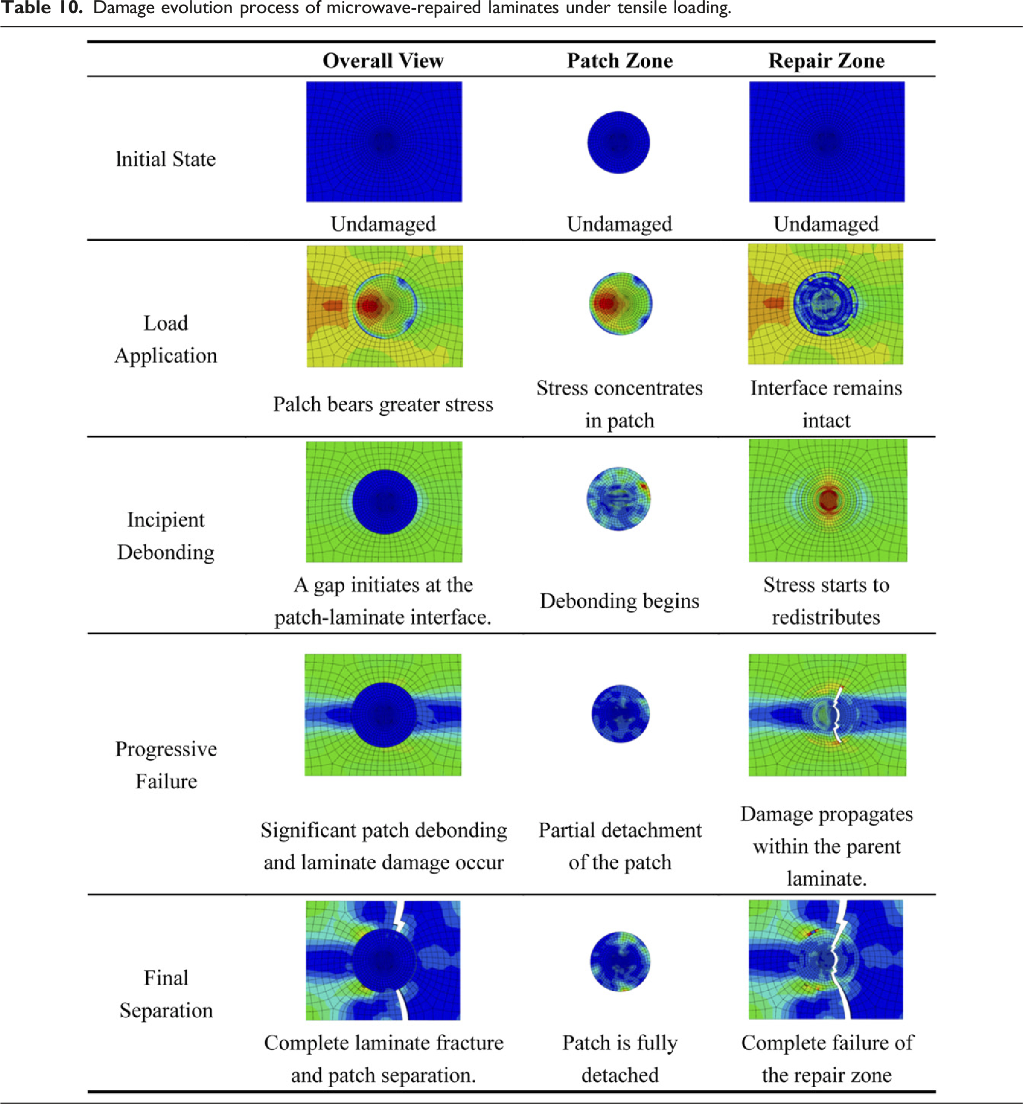
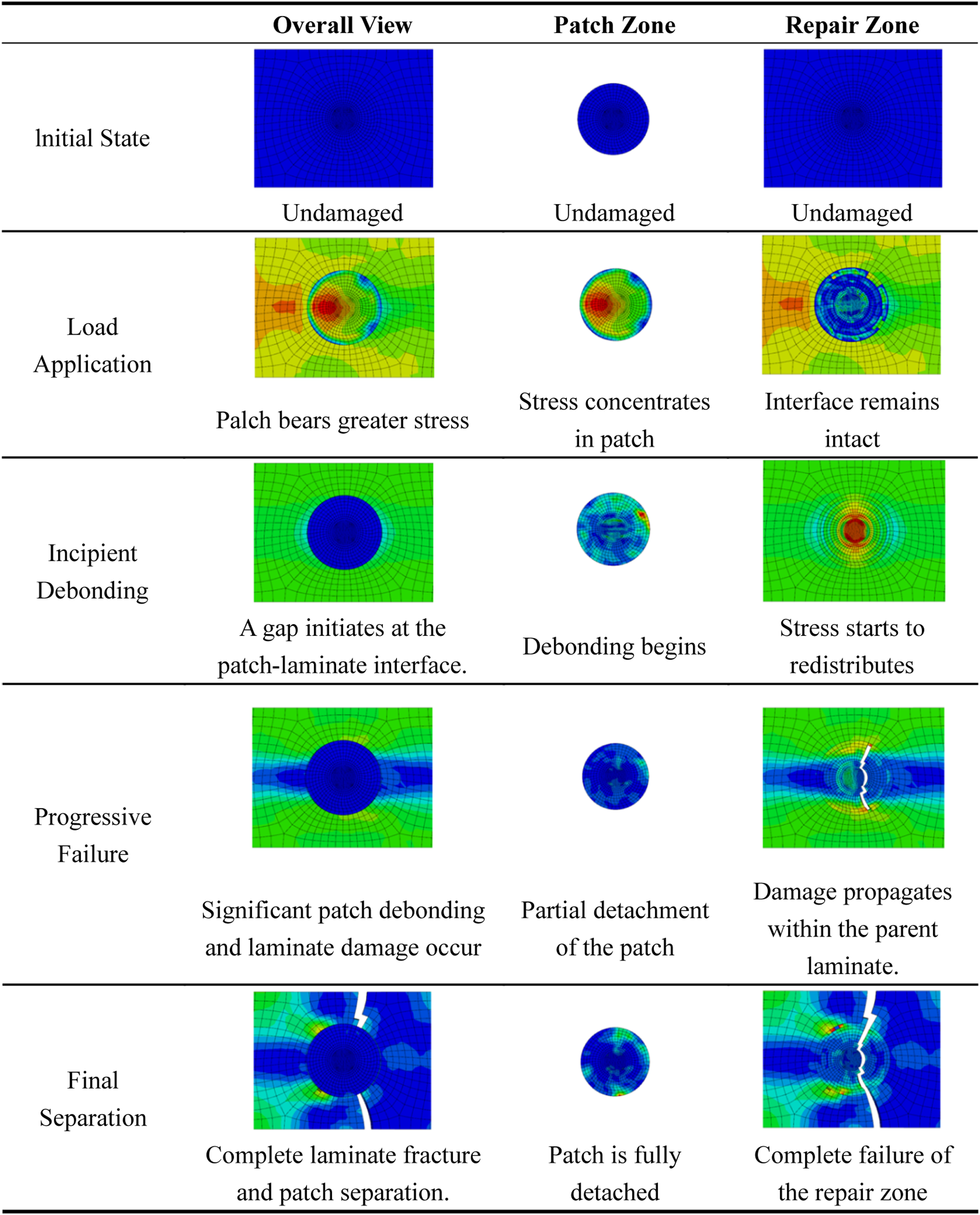
Damage evolution process of microwave-repaired laminates under tensile loading.
Failure analysis of skin-repaired laminates (Scheme 2)
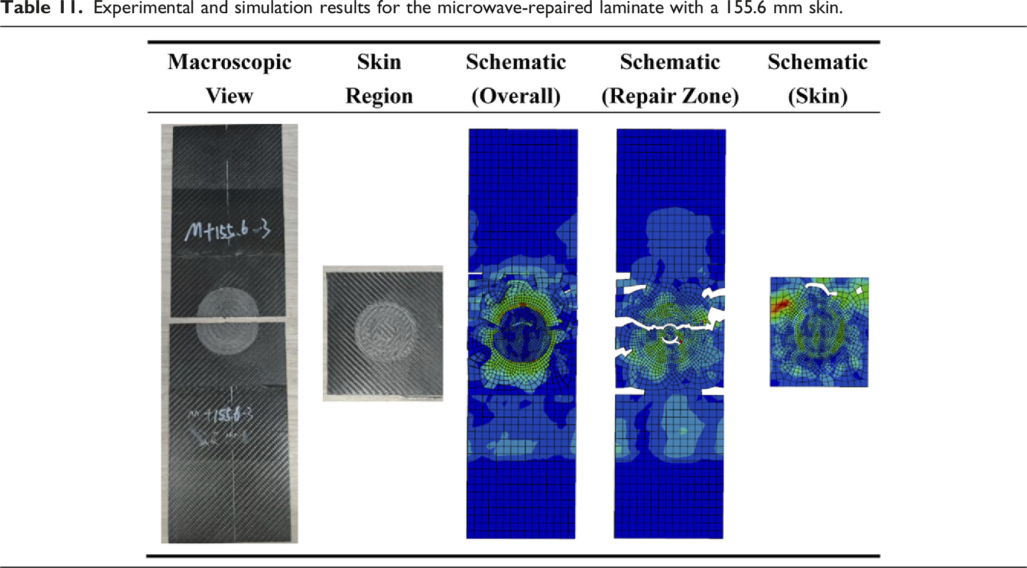
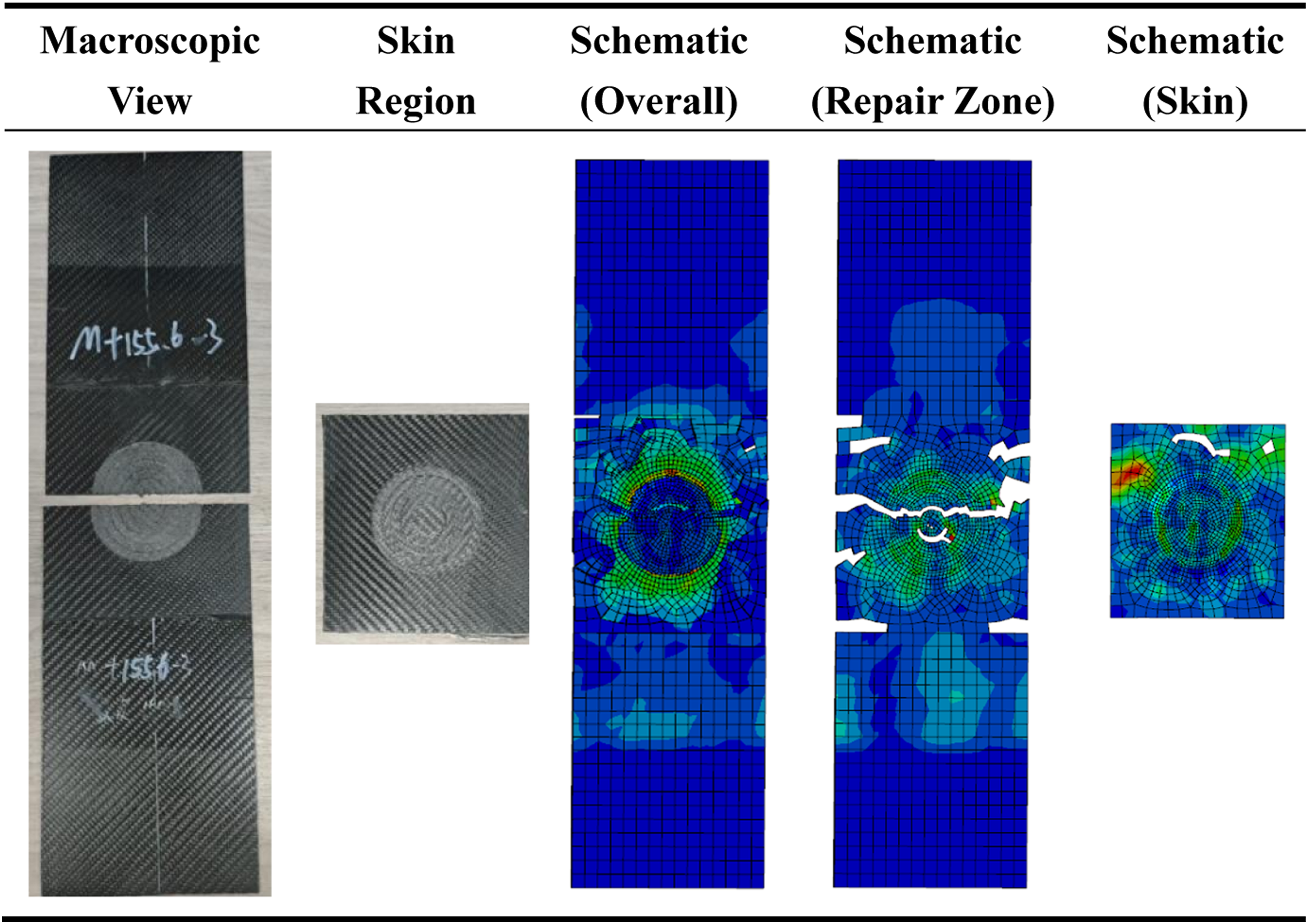
Experimental and simulation results for the microwave-repaired laminate with a 155.6 mm skin.
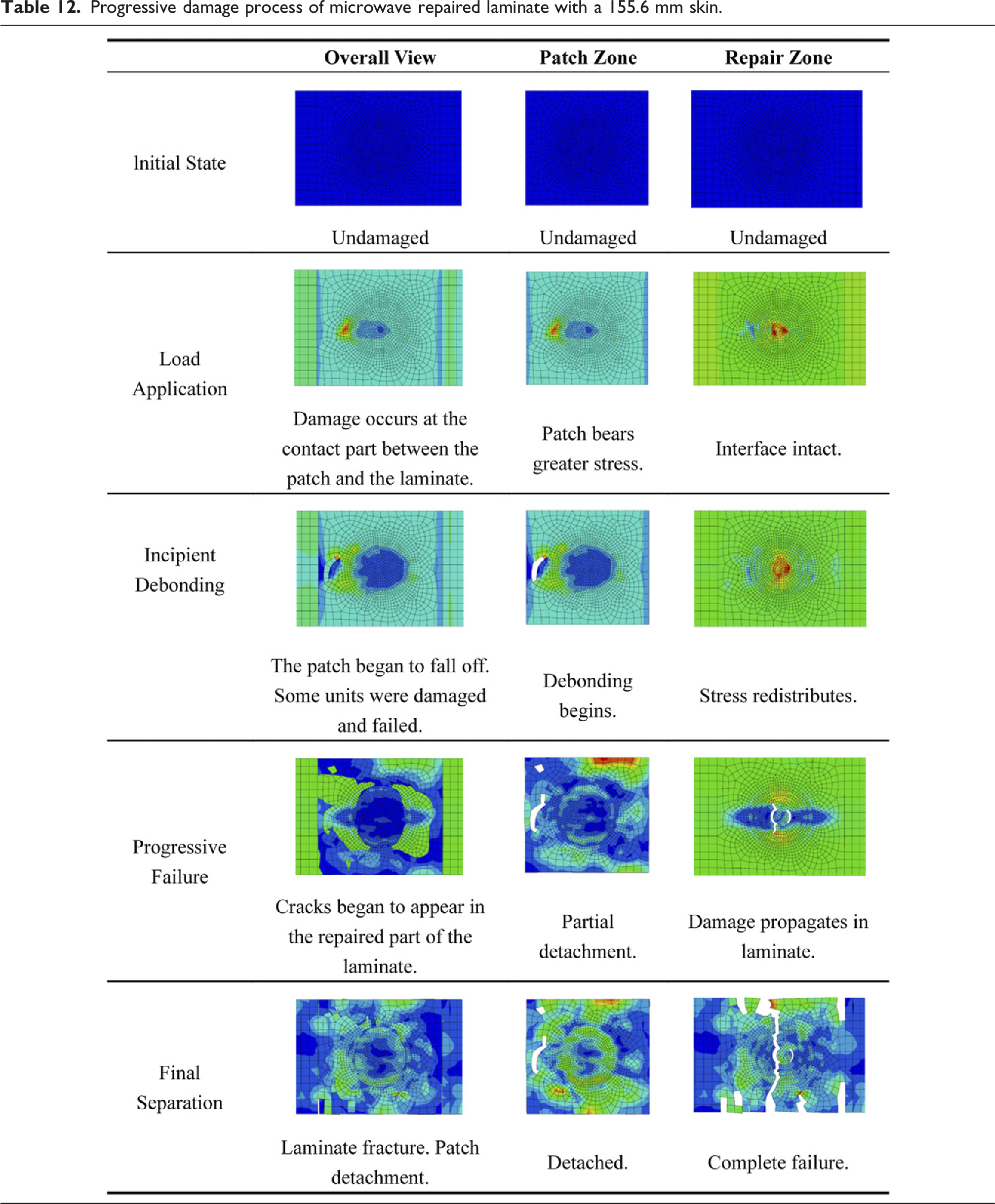
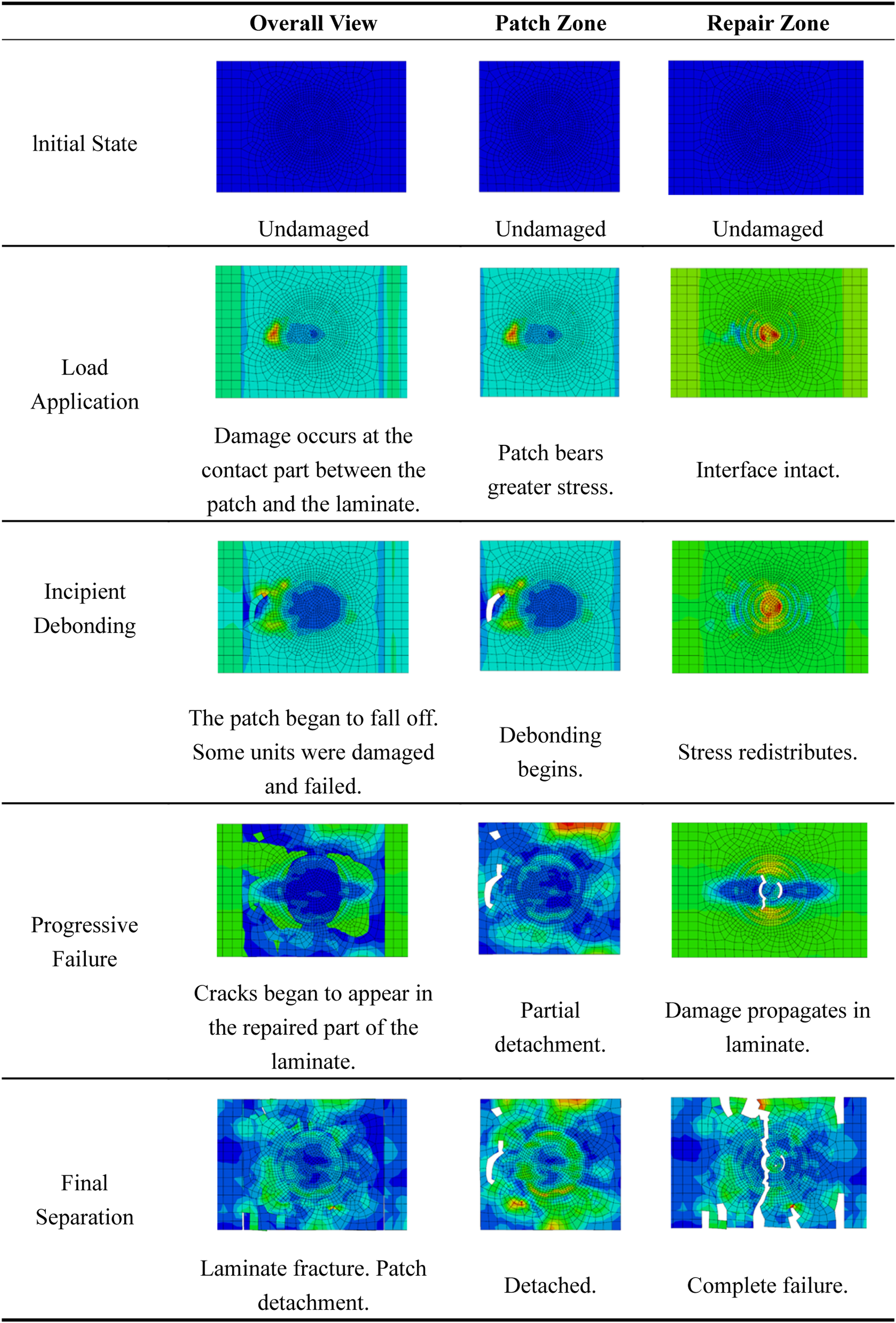
Progressive damage process of microwave repaired laminate with a 155.6 mm skin.
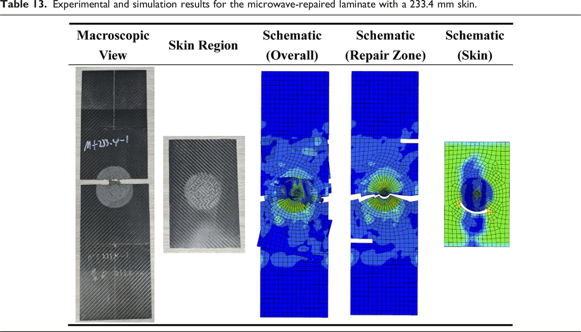
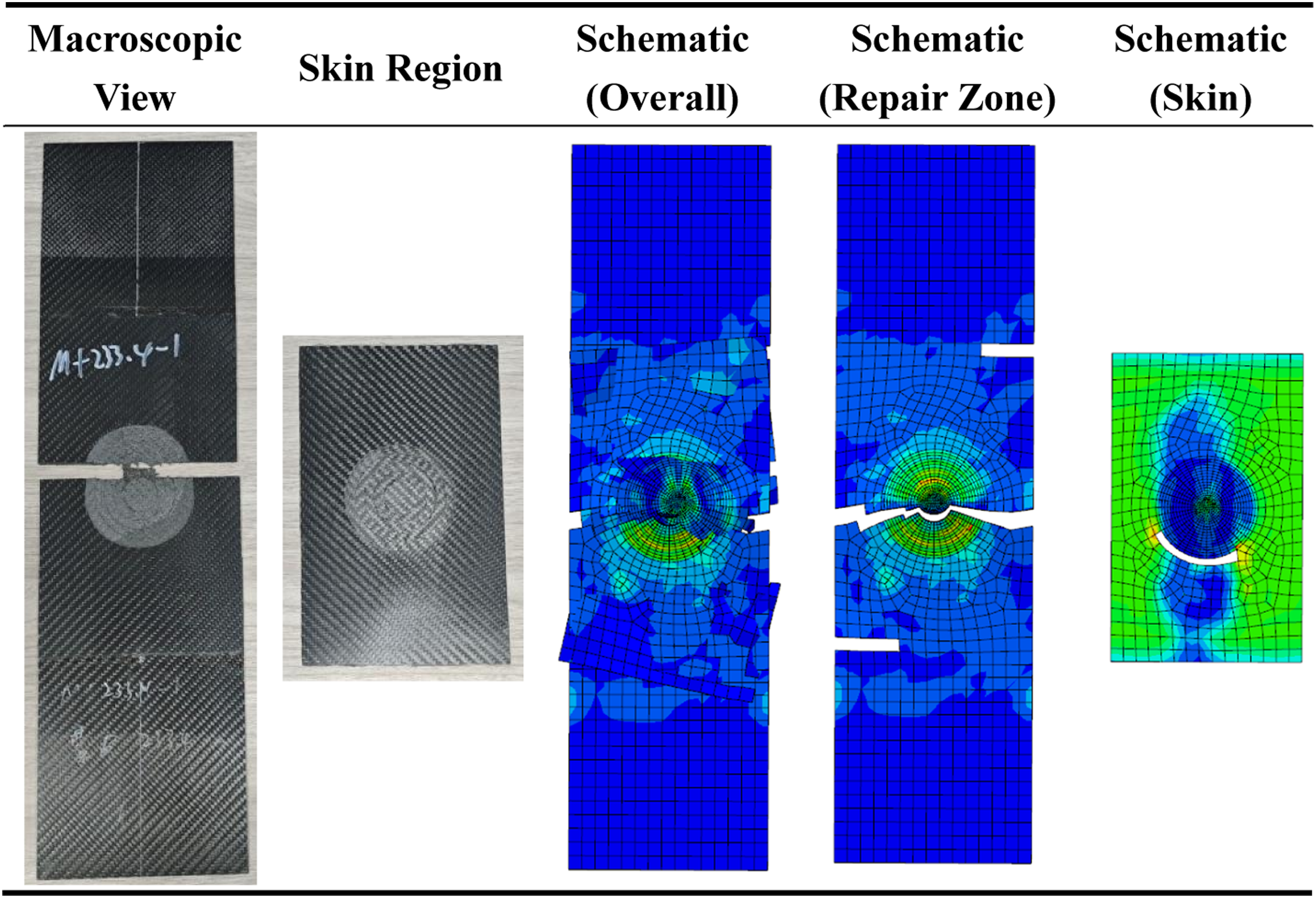
Experimental and simulation results for the microwave-repaired laminate with a 233.4 mm skin.
Progressive damage process of microwave repaired laminate with a 233.4 mm skin.
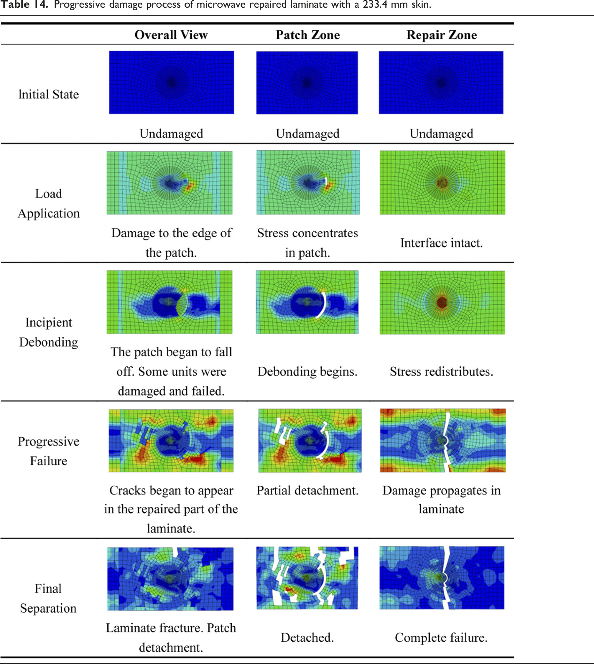
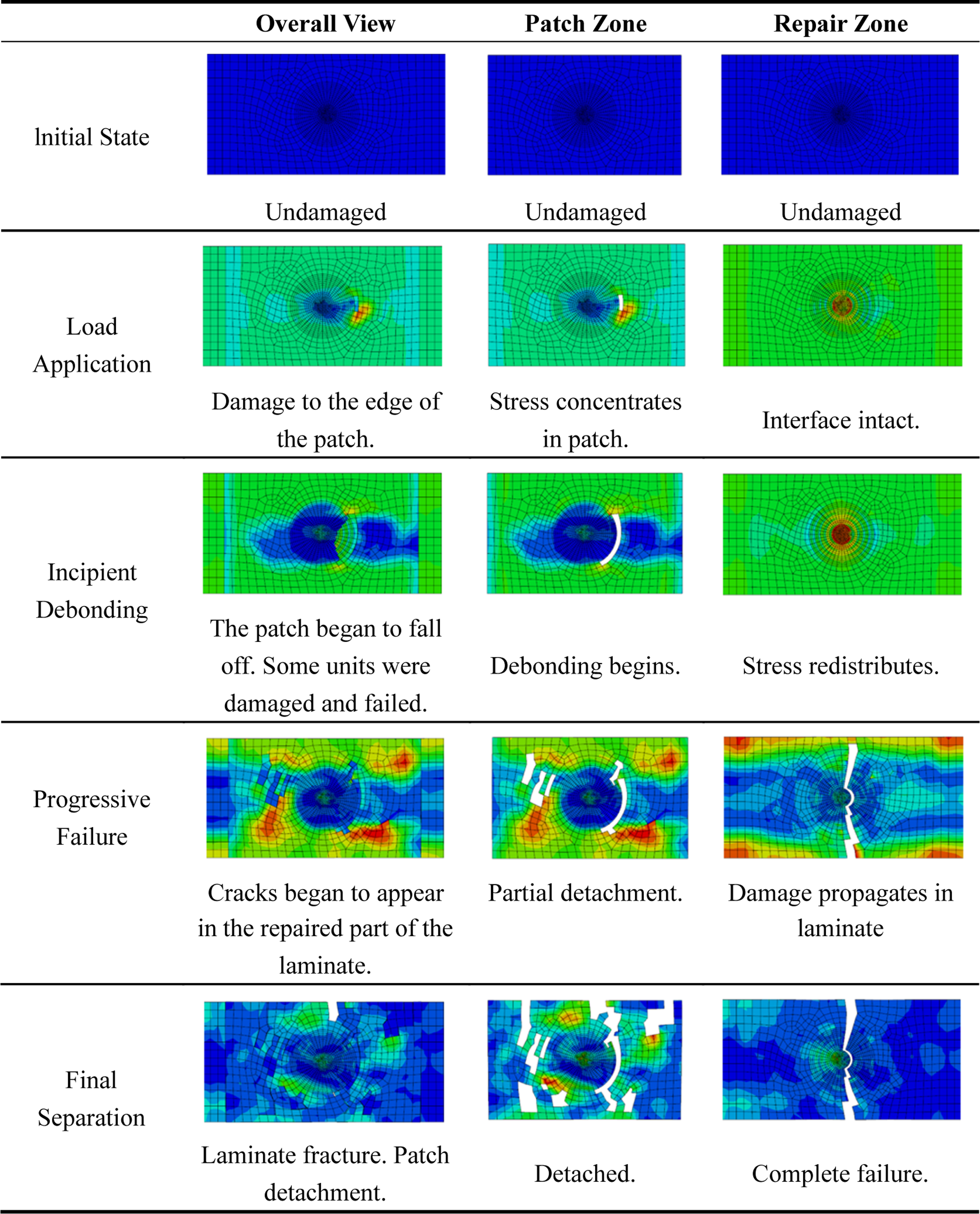
The strong congruence between the mechanical test results and the corresponding finite element simulations presented in Sections 4.3.2 and 4.3.3 successfully validates the effectiveness and predictive accuracy of the developed progressive damage model for analyzing repaired carbon fiber composite laminates, which aligns with the failure behaviors observed for skin repair in related studies. 9
Optimized skin repair model
Exploratory optimization: Full-length skin repair
Building on the understanding that skin reinforcement improves load sharing and that longer skins are more effective, an optimized repair configuration was simulated. This configuration featured a full-length skin identical in planar dimensions to the parent laminate (525 mm × 145 mm), effectively creating a locally reinforced, symmetric laminate (Figure 15). Schematic diagram of the 525 mm skin repair laminate model.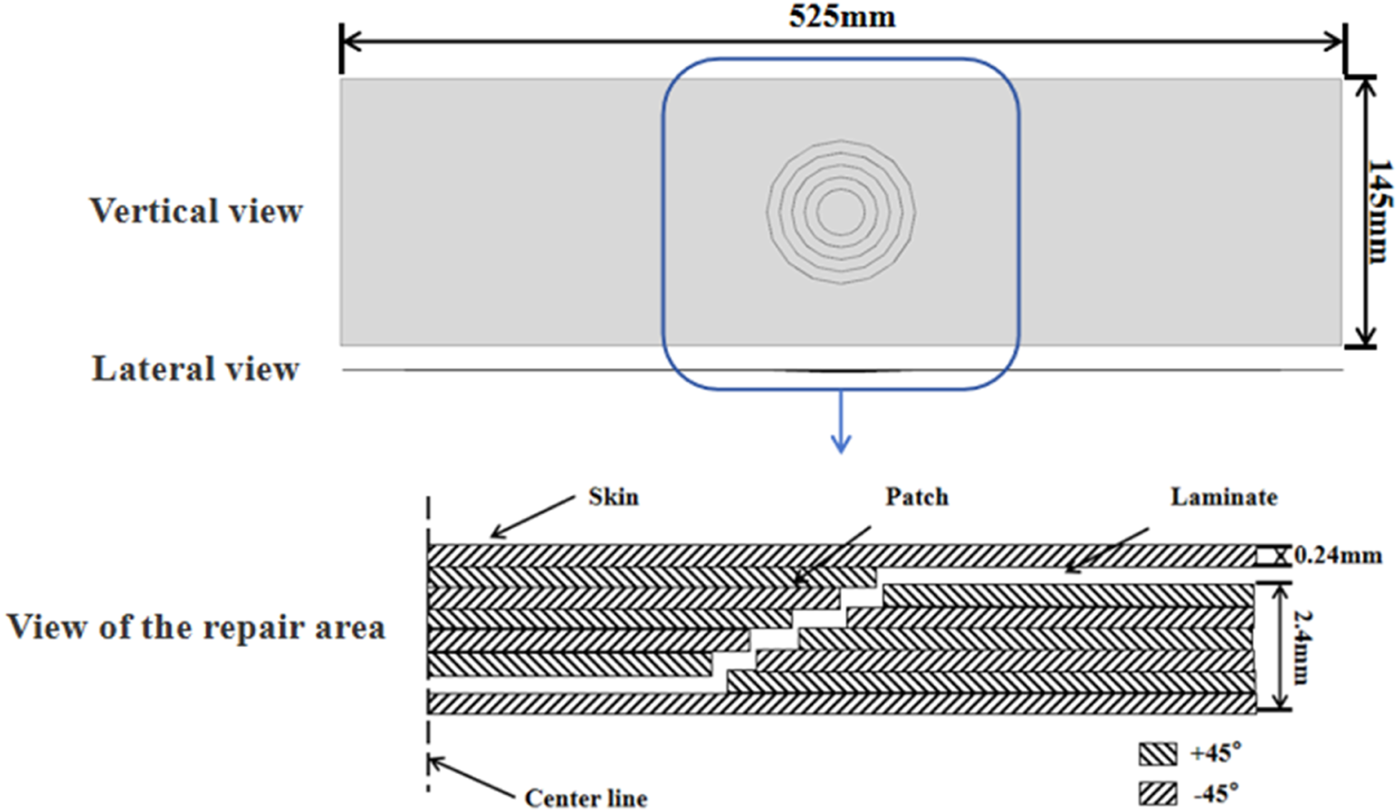
The simulation predicted outstanding performance, with an ultimate load of 185.1 kN, corresponding to a repair efficiency of 92.6% relative to the undamaged laminate (Figure 16). The load-displacement curve indicates that the initial tensile stiffness is nearly fully restored. More importantly, the curve exhibits an extended non-linear domain prior to failure, indicative of stable, progressive damage accumulation rather than sudden brittle fracture. Simulated tensile response of the full-length skin repair model compared to the undamaged baseline.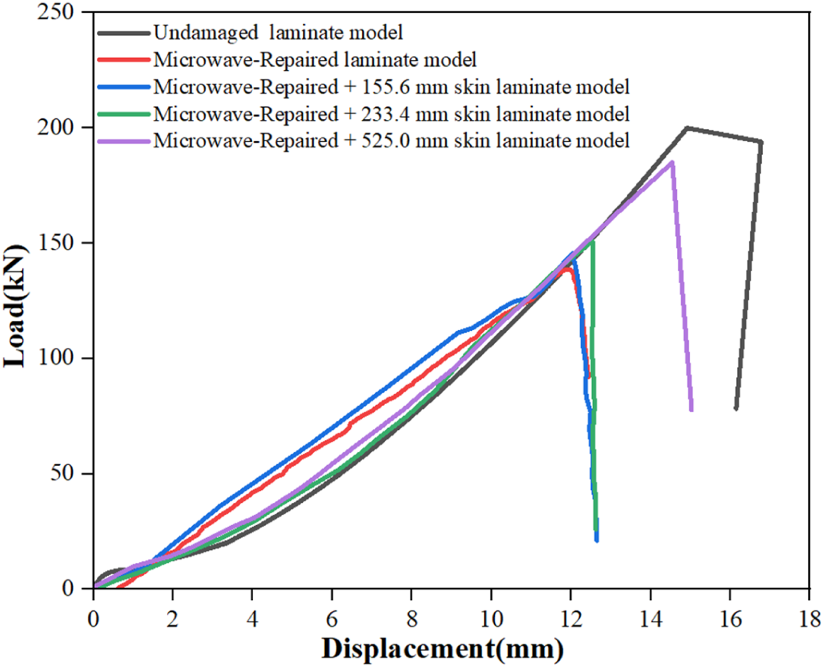
The exceptional performance is mechanistically explained by a complete transition in the load-bearing paradigm. The full-length skin is seamlessly integrated into the primary load path, functioning as a co-primary tension member. Consequently, the repair is no longer a local reinforcement but a globally optimized, locally thickened section. The stress analysis confirms a drastic reduction in the peel and shear stresses at the original repair boundary.
The resultant failure mode, depicted in Figure 17, validates this shift. Failure is no longer driven by debonding. Instead, it occurs due to cohesive tensile fracture of the parent laminate within the gauge section, accompanied by subsequent or simultaneous fracture of the overlying skin. The damage initiates from the original flaw in the parent material and propagates stably, with the skin remaining bonded and actively sharing load until final rupture. This represents the most efficient possible failure mode, as it engages the strength of the base composite to the greatest extent. The transition of the failure mode, from interfacial debonding dominance to the synergistic tensile fracture of both the parent material and the skin, is a typical characteristic of highly integrated structural repair, indicating higher repair efficiency.
27
Simulated damage morphology of the optimized repair: (a) overall view showing combined fracture, (b) detail of the fracture region.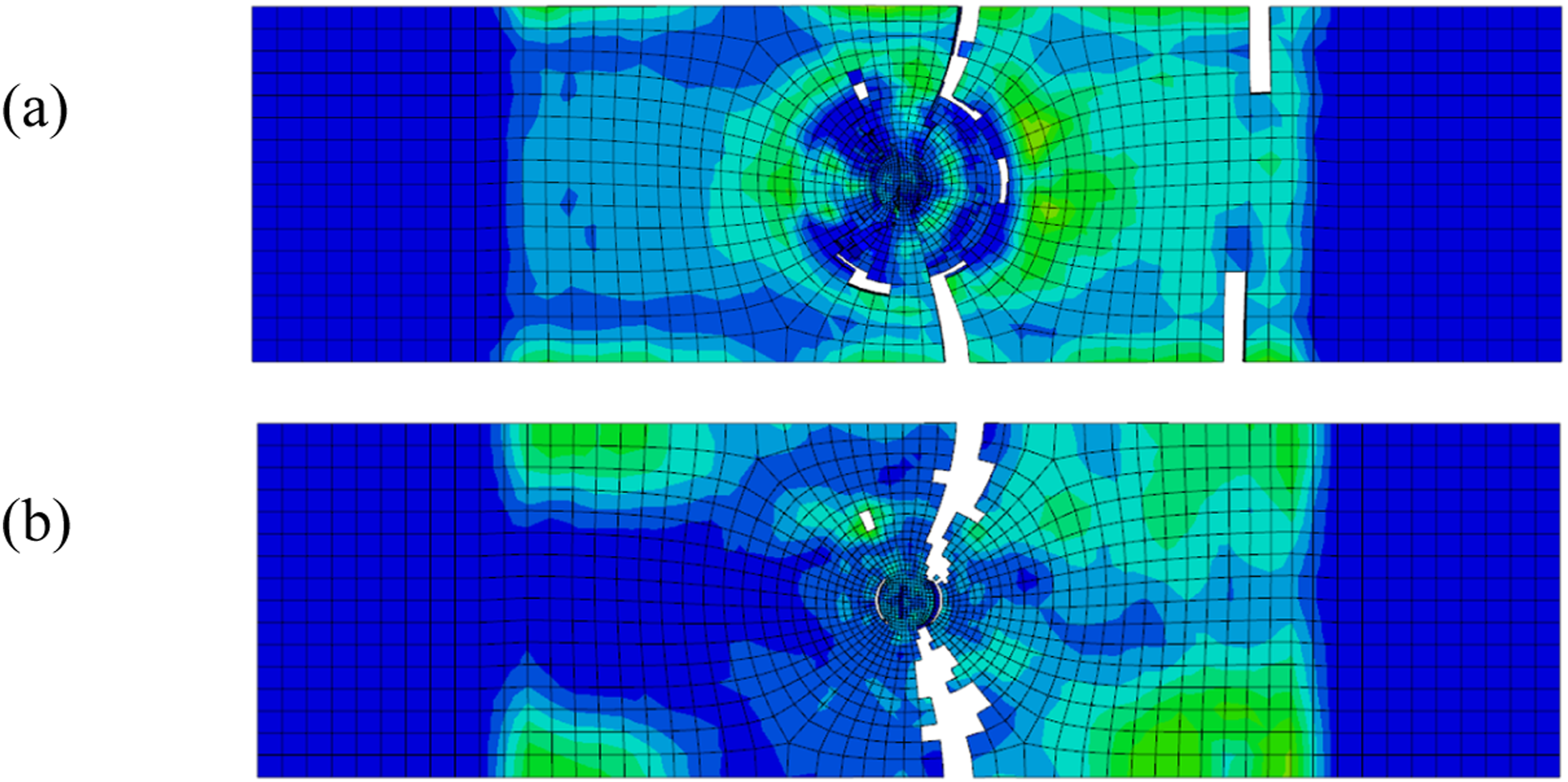
The optimization model establishes the performance upper limit for full-scale skin repair. Its core design principles, maximizing the bonding area and ensuring the repair patch integrates into the overall load-transfer path show strong agreement with the design philosophy for high-performance adhesive repair previously reported in the literature. 13 The full-length skin model establishes a theoretical performance upper bound for the given material system and repair philosophy. It crystallizes a core design principle for high-performance bonded repairs: maximizing the bonded repair area and ensuring its integration into the global load-carrying structure is paramount for restoring structural integrity. While practical constraints may preclude implementing a full-length skin in all scenarios, this finding provides a clear direction for optimization, extending the repair reinforcement to overlap with load-introduction points (e.g., fastener rows, adjacent stiffeners) to approach this ideal load-sharing condition. This study successfully transitions from observing a performance trend (longer skins work better) to explaining its root cause (improved load sharing and altered failure mode) and finally to defining its theoretical limit through physics-based simulation.
Conclusions
This study established a microwave-assisted skin-integrated repair (MSIR) strategy for the rapid and high-performance restoration of damaged CFRP laminates. The key findings, integrating experimental validation and mechanistic insight, are summarized as follows: (1) Rapid Microwave Curing with High Degree of Cross-linking: The optimized microwave process achieved a near-full cure (>99.9%) within 15 min, representing a reduction of over 99% in processing time compared to conventional room temperature methods. This efficiency is attributed to volumetric heating via dielectric loss and fiber conduction. (2) Mechanism Transition from Interfacial Debonding to Synergistic Fracture: Experimental and numerical analyses revealed that patch-only repairs are limited by interfacial debonding (72.9% efficiency). In contrast, the integrated skin functions as a load-sharing member, redistributing stress concentrations and shifting the failure mode to synergistic tensile fracture of the parent laminate and the skin. (3) Performance Upper Bound via Load-Path Integration: Incorporating a 233.4 mm skin increased repair efficiency to 80.5%. Simulation-guided optimization of a full-length skin configuration predicted a repair efficiency of 92.6%, establishing the theoretical upper bound by transforming the repair zone into a globally integrated load-bearing structure. (4) Validation of a Predictive Progressive Damage Framework: A 3D finite element model, validated with experimental data (error <5.5%), successfully captured the transition from debonding to cohesive fracture, providing a reliable computational tool for designing high efficiency bonded repairs.
Footnotes
Acknowledgments
The authors would like to acknowledge Wuxi Rele Advanced Material Technology Co., Ltd, Wuxi, China, for providing the customized industrial microwave curing oven (Model: TK-18 GW) and their technical support during the repair experiments. The use of this specialized equipment was crucial for the successful implementation of the rapid microwave curing process central to this study.
Funding
The authors received no financial support for the research, authorship, and/or publication of this article.
Declaration of conflicting interests
The authors declared no potential conflicts of interest with respect to the research, authorship, and/or publication of this article.
Data Availability Statement
The data are available from the corresponding author on reasonable request.