
Abstract
This study develops a microscale constitutive model to characterize the mechanical and creep strain response of fiber-reinforced ceramic matrix composites (CMCs) under stepwise loading at elevated temperatures, explicitly accounting for oxidation of both the interphase and reinforcing fibers. The model incorporates four key creep-induced damage mechanisms: stress-dependent stochastic matrix cracking, time-dependent interface oxidation, stress–oxidation–coupled interface debonding, and stochastic fiber failure. By systematically integrating the interactions between interface slip and matrix cracking, six distinct damage configurations—termed Mode I through VI—are defined based on matrix crack spacing (long, mediate, short) and interface degradation state (partial vs full debonding, with or without oxidation). These configurations serve as the physical basis for deriving the microscale creep constitutive relations. The model is applied to predict the time-dependent mechanical and creep strains of a 2.5D SiC/SiC composite under constant and stepwise elevated-temperature loading, with results differentiated across all six damage modes. Parametric analyses quantify the effects of stepwise load magnitude and dwell time, as well as creep temperature, on global strain evolution and internal damage progression—including fiber fracture, interface oxidation kinetics, and debonding extent. Model predictions are validated against experimental strain data for the same 2.5D SiC/SiC composite tested under stepwise loading at 1000°C, 1100°C, and 1300°C. Finally, quantitative relationships linking cumulative creep strain to stepwise loading history and progressive damage accumulation are established.
Keywords
Introduction
Ceramic matrix composites (CMCs) are a class of advanced structural ceramics engineered specifically to mitigate the intrinsic brittleness and low fracture toughness inherent in monolithic ceramics. 1 A typical CMC comprises high-performance ceramic fibers, most commonly silicon carbide (SiC) or carbon, embedded within a ceramic matrix, frequently incorporating a tailored interphase layer that facilitates controlled crack deflection, bridging, and interfacial energy dissipation. This hierarchical microstructure allows CMCs to retain the defining attributes of ceramics, i.e., exceptional high-temperature stability, oxidation resistance, low density, and chemical inertness, while concurrently delivering markedly enhanced damage tolerance, superior thermal shock resistance, and pseudo-ductile failure behavior under mechanical loading.2,3 Relative to nickel-based superalloys and conventional monolithic ceramics, CMCs uniquely combine low areal density with outstanding thermomechanical performance at elevated temperatures. They sustain continuous service at temperatures above 1200°C, thereby enabling substantial simplification or even elimination of active cooling systems in gas turbine hot-section components and jet engine combustors.4,5 As a result, propulsion systems benefit from improved thermodynamic efficiency, reduced CO2 and NOx emissions, and lower specific fuel consumption. Principal applications include aerospace hot-section components (e.g., turbine shrouds, combustor liners, and nozzle flaps), carbon–carbon–ceramic brake discs for high-speed vehicles, atmospheric re-entry thermal protection systems, and high-temperature industrial heat exchangers.6–9 Owing to their unparalleled balance of lightweight design, extreme-temperature capability, and structural reliability, CMCs constitute a foundational enabling technology for next-generation propulsion, power generation, and hypersonic systems. However, under sustained mechanical loading at elevated temperatures (typically >1000°C), they exhibit time-dependent deformation known as creep.10–12 Understanding creep behavior is critical for predicting long-term component life in gas turbines, hypersonic vehicles, and nuclear reactors.
Experimental creep studies on CMCs are typically conducted under uniaxial tensile or flexural loading at constant temperature and applied stress, commonly in ambient air or controlled inert atmospheres.13–16 For SiC/SiC composites, the creep response exhibits the classical three-stage behavior: primary creep (characterized by a decreasing strain rate), secondary creep (a quasi-steady-state regime with a minimum, nearly constant strain rate), and tertiary creep (marked by accelerating strain accumulation culminating in macroscopic failure).17–19 In contrast to monolithic ceramics which undergo abrupt, brittle fracture, CMCs exhibit progressive, non-catastrophic creep rupture enabled by extrinsic toughening mechanisms, notably fiber bridging across matrix cracks and crack deflection along weak interfaces. Acoustic emission (AE) monitoring was employed to identify the dominant damage mechanisms occurring during creep loading. Specifically, four distinct damage mechanisms of matrix cracking, interfacial debonding, fiber fracture, and fiber bundle fracture were systematically correlated with characteristic AE signal features, including frequency content and energy magnitude.20,21 The steady-state creep rate obeys a power-law dependence on applied stress, with a stress exponent n ranging from approximately 1.0 to 3.0 for SiC/SiC CMCs, significantly lower than the n ≈ 5–10 observed for monolithic SiC.22–24 This reduced exponent reflects a fundamental shift in rate-controlling mechanism: creep in CMCs is governed predominantly by interfacial sliding, fiber–matrix frictional dissipation, and time-dependent debonding, rather than by thermally activated dislocation climb or diffusion-controlled processes within the matrix lattice alone.25–27 Architecturally, cross-ply and woven SiC/SiC composites demonstrate lower steady-state creep rates than unidirectional laminates, as transverse fibers constrain matrix crack opening, impede crack propagation perpendicular to the loading direction, and promote more uniform load redistribution among intact fibers.28–31 Under oxidizing conditions, CMCs are susceptible to stress-oxidation–assisted creep: oxygen ingress occurs preferentially through pre-existing matrix microcracks, leading to oxidation of the interphase (e.g., boron nitride (BN) or pyrolytic carbon (PyC)).32–35 In severe cases, degradation of the SiC fibers themselves; the resulting silica (SiO2) reaction products may partially seal cracks but concurrently induce interfacial embrittlement and fiber strength loss.36–38 Consequently, both creep strain accumulation and time-to-failure are markedly reduced. Final rupture proceeds via sequential fiber fracture, progressive interfacial decohesion, and eventual fiber pull-out, the processes that collectively govern the composite’s time-dependent structural integrity. Consistent with metallic and advanced ceramic systems, the time-to-rupture of SiC/SiC CMCs correlates linearly with the inverse of the minimum creep strain rate (1/ε̇min) in log–log space, following the Monkman–Grant relationship.39–42
Theoretical modeling efforts seek to quantitatively capture the coupled microstructural evolution encompassing matrix creep, interfacial degradation, fiber damage, and oxidation-driven changes that governs time-dependent deformation and failure in CMCs under sustained loading.11,28,38,40,43,44 Shear-lag–based models idealize the composite as a periodic array of continuous fibers embedded in a creeping ceramic matrix. 45 Matrix creep strain rate is governed by a Norton–Bailey power law (ε̇ = Aσn exp (−Q/RT)), incorporating both stress and temperature dependence.46,47 The model explicitly resolves axial stress transfer from the deforming matrix to load-bearing fibers, predicting progressive fiber stress intensification, time-dependent composite strain accumulation, and eventual fiber fracture under critical local stress. Recognizing that the fiber/matrix interphase commonly boron nitride (BN) or pyrolytic carbon (PyC) exhibits time-dependent shear compliance and oxidative degradation, interface-controlled creep models treat interfacial sliding, wear, and debonding as rate-controlling processes.48–50 The overall composite creep rate is formulated as the sum of contributions from matrix viscoplastic flow and interfacial shear relaxation, with interface properties evolving as functions of stress, temperature, time, and oxygen partial pressure. Continuum damage mechanics (CDM)-based approaches introduce internal state variables, including matrix crack density, fiber breakage probability, interfacial oxidation length, and interphase thickness loss, to represent evolving microstructural damage.51–53 Evolution laws for these variables are thermodynamically consistent and coupled to the constitutive equations for creep strain, enabling robust simulation of primary, secondary, and tertiary creep regimes, including acceleration prior to rupture. Multi-scale finite element method (FEM) models explicitly resolve representative volume elements (RVEs) featuring realistic woven or braided architectures, stochastic fiber positioning, and geometrically accurate interphase layers.54,55 Constituent-specific, temperature- and stress-dependent creep laws, often calibrated against experimental data, are assigned to each phase. State-of-the-art implementations integrate coupled chemo-mechanical formulations, linking local oxygen diffusion, interphase oxidation kinetics, and mechanical degradation to predict spatially resolved damage progression and lifetime under oxidizing environments. Life prediction models: Semi-empirical methodologies, including the Larson–Miller parameter, and physics-informed stochastic fiber failure models provide practical engineering tools for estimating time-to-rupture as a function of applied stress, temperature, and environmental exposure duration. 56
In service, CMC components are rarely subjected to monotonic loading; rather, they experience complex, non-proportional stress histories characterized by multi-step load increments, repeated load–unload cycles, and variable-amplitude fatigue.57,58 Accurate characterization of stepwise loading behavior—defined as the application of stress in discrete, incremental steps rather than continuous ramping—is therefore critical for reliable life prediction, damage-tolerant design, and structural integrity assessment under realistic operating conditions.59–61 Experimental studies on stepwise loading in CMCs have predominantly employed tension–tension fatigue protocols under multi-stage stress-controlled conditions. For 2D woven C/SiC composites, axial multi-stage tensile testing reveals a distinctive three-stage degradation profile (“fast–slow–fast”) in the unloading modulus versus cycle number, concomitant with progressive accumulation of residual (permanent) strain.62–64 Scanning electron microscopy (SEM) fractography corroborates this behavior, identifying concurrent activation of multiple damage mechanisms: matrix microcracking, interfacial debonding, and fiber pull-out—each evolving in sequence and intensity with increasing damage accumulation. In SiC/SiC composites, AE monitoring has emerged as a powerful in situ diagnostic tool during stepwise cyclic loading. The observed Kaiser effect—wherein AE activity remains suppressed until the previously attained maximum stress level is exceeded—provides direct experimental evidence of nonlinear, history-dependent damage accumulation, reflecting the irreversible nature of interfacial and matrix damage.19,65 Crucially, high-energy AE events correlate strongly with macroscopic matrix crack coalescence and discrete fiber fracture events, enabling quantitative, real-time mapping of damage initiation, localization, and propagation kinetics. Notably, certain C/SiC systems exhibit a post-fatigue strength enhancement of up to ∼20% in ultimate tensile strength—a phenomenon termed “fatigue-induced strengthening,” attributed to the gradual relaxation of localized stress concentrations through microstructural accommodation (e.g., interface wear, partial debonding, and matrix crack blunting).66–68 Significant theoretical advances have been achieved in modeling stepwise loading response. Wang et al. 69 performed cyclic tensile loading–unloading experiments on a 2D C/SiC composite to systematically investigate the load-dependent evolution of microscale damage mechanisms and subsequently formulated a physics-informed microscale damage model. Using this model, the cyclic stress–strain hysteresis loops were accurately predicted. Li 70 developed a micromechanics-based damage evolution model for C/SiC composite under multi-step tensile loading, explicitly resolving axial stress redistribution in fibers across spatially heterogeneous interface damage zones (intact, partially debonded, fully debonded). The model quantitatively predicts hysteresis loop shape, magnitude, and evolution—including interface slip length and fiber stress gradients—for diverse loading sequences (e.g., low–high vs high–low stress stepping), with strong agreement against experimental data. Extending this framework to time-dependent failure, Li 71 formulated a coupled chemo-mechanical constitutive model for stress rupture at 950°C in oxidative environments, incorporating multi-stage loading histories. This model tracks the concurrent evolution of matrix crack spacing, interfacial debonding length, interphase oxidation depth, and probabilistic fiber failure under both single- and multi-step loading paths. Liu et al. 72 investigated the damage evolution mechanisms in unidirectional and cross-ply SiC/SiC composites by integrating AE monitoring with macroscopic mechanical testing, thereby establishing quantitative correlations between macroscopic stress–strain behavior and cumulative microscale damage events—such as matrix microcracking, interfacial debonding, and fiber fracture. The experimentally observed cyclic stress–strain hysteresis loops were successfully reproduced using the calibrated microscale damage models. Liu et al. 73 developed a continuum damage model to predict both the stress–strain response and progressive stiffness degradation in oxide/oxide composites under monotonic and cyclic loading conditions. To distinguish between distinct degradation pathways, two anisotropic damage evolution laws—specifically formulated for monotonic and cyclic loading, respectively—were incorporated into the framework. Nevertheless, existing damage-based models, including this one, do not explicitly account for microscale damage features such as matrix microcracking, interfacial debonding, or localized fiber fracture. Key findings demonstrate that multi-step loading accelerates interfacial degradation and oxidation penetration, resulting in higher fiber breakage fractions and significantly reduced stress-rupture lifetimes relative to equivalent single-step loading. Under thermomechanical fatigue involving combined thermal cycling and multi-step mechanical loading, cumulative damage exceeds that induced by any single peak stress alone.
In recent years, substantial research efforts have been directed toward elucidating the creep damage mechanisms of fiber-reinforced CMCs under elevated temperatures and oxidizing atmospheres. Initial investigations emphasized time-dependent phenomena including matrix microcracking, fiber/matrix (F/M) interfacial sliding, and fiber fracture. More recently, advanced in situ and post-fracture characterizations have demonstrated that creep–oxidation coupling entails a progressive shift from matrix-dominated to fiber-dominated deformation, concurrent with the formation of a silica-rich layer on fiber surfaces and oxidative embrittlement of the F/M interface. These coupled processes exhibit strong dependence on the stress history—particularly under stepwise or variable-amplitude loading conditions representative of actual gas turbine engine cycles. Constitutive modeling of CMCs under creep has accordingly advanced from phenomenological frameworks to micromechanics-informed damage models. However, the majority of existing models assume either constant stress or monotonic stress increase; their predictive capability for realistic stepwise loading sequences remains poorly established. Furthermore, most models treat creep and oxidation as independent processes, failing to incorporate a mechanistically grounded coupling between oxidation-driven interfacial degradation and the temporal sequence of applied stress steps. Critically, even those models developed for stepwise loading are typically calibrated and validated solely against macroscopic strain measurements, without resolving underlying microscale damage evolution—despite its decisive role in governing nonlinear strain accumulation under variable loading. To bridge these gaps, this study proposes a microscale constitutive model that explicitly couples creep deformation, interfacial oxidation kinetics, and the chronological progression of stepwise mechanical loading in fiber-reinforced CMCs. The model mechanistically represents time-dependent interfacial silica growth, associated reduction in interfacial shear stress, progressive fiber strength degradation due to surface oxidation, and the memory effect of prior loading steps on subsequent creep–oxidation response. Validation is performed against high-fidelity experimental stepwise creep data reported in the literature; results confirm the model’s capacity to quantitatively reproduce the distinct strain evolution—including transient and steady-state regimes—during each individual loading segment. This work therefore establishes a physically consistent, microscale-resolved framework for predicting coupled creep–oxidation–stepwise loading strain behavior, addressing a fundamental limitation in current CMC constitutive modeling.
This study establishes a microscale creep strain model for CMCs subjected to stepwise loading at elevated temperatures, with explicit incorporation of interphase and fiber oxidation. The model integrates four fundamental creep-induced damage mechanisms—stress-dependent stochastic matrix cracking, time-dependent interface oxidation, stress–oxidation–coupled interface debonding, and load redistribution–driven stochastic fiber failure—within a unified constitutive framework tailored to six distinct matrix cracking configurations (Mode I–VI). These configurations are systematically defined by matrix crack spacing (long, intermediate, short) and interface degradation state (partial vs full debonding, with or without concurrent oxidation). Using the proposed model, the time-dependent creep strain response of a 2.5D SiC/SiC composite under both constant and stepwise loading is quantitatively predicted across all six modes. Parametric analyses rigorously assess the influence of stepwise load magnitude, dwell duration, and creep temperature on global strain accumulation and the evolution of associated microscale damage—including debonded interface length, and fiber fracture fraction. Model predictions for creep strain under stepwise loading at 1000°C, 1100°C, and 1300°C are validated against experimental measurements. The paper is organized as follows: Section Theory Models presents the theoretical foundations, including the microscale damage models (stochastic matrix cracking governed by local stress; interface oxidation kinetics governed by oxygen time and temperature; stress–oxidation–coupled debonding criterion; and fiber failure governed by global load sharing and accumulated damage) and the corresponding microscale creep constitutive relations for each of the six cracking configurations. Section Model Validation reports and discusses the numerical results, highlighting mode-dependent strain responses, parametric sensitivities, and damage progression pathways under constant and stepwise loading. Section Experimental Comparisons details experimental validation, comparing predicted and measured creep strains for the 2.5D SiC/SiC composite tested under identical stepwise thermal–mechanical conditions. Section Summary and Conclusions concludes with key findings and implications for life prediction and design of high-temperature CMC components.
Theory models
Figure 1 presents the conceptual schematic framework of the microscale creep constitutive model developed in this study. The macroscopic composite strain comprising elastic strain and time-dependent creep strain is explicitly coupled to four physically grounded microscale damage mechanisms: (i) stress-dependent statistical matrix cracking, (ii) time-dependent interfacial oxidation, (iii) fracture mechanics–based interfacial debonding, and (iv) global load-sharing–based statistical fiber failure. Critically, the model adaptively activates one of six discrete damage states—Mode I (long crack + partial oxidation), Mode II (long crack + complete oxidation), Mode III (medium crack + partial oxidation), Mode IV (medium crack + complete oxidation), Mode V (short crack + partial oxidation), and Mode VI (short crack + complete oxidation)—according to the instantaneous combination of crack length and interfacial oxidation extent within the composite. A conceptual schematic framework for microscale creep constitutive model.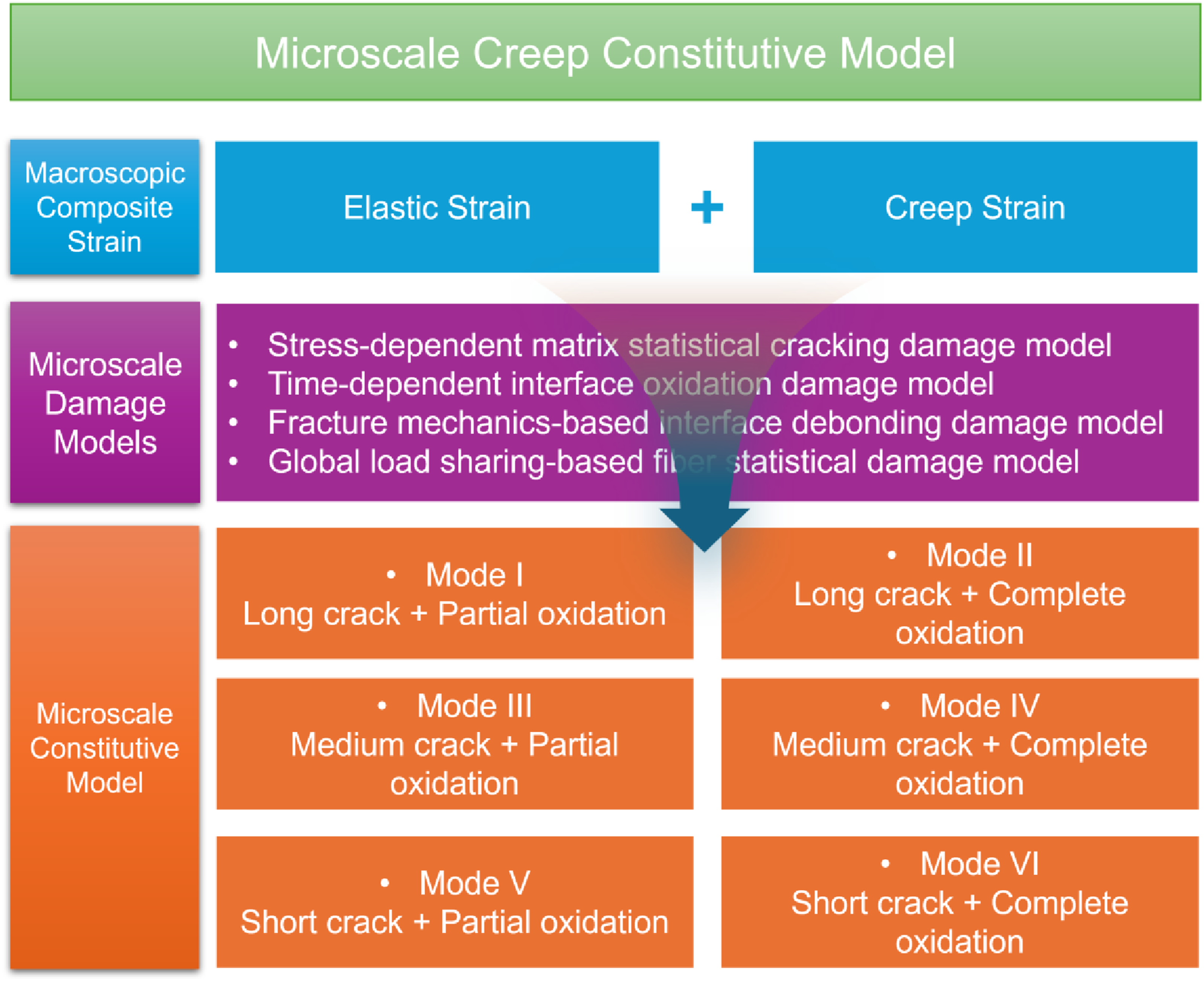
This section develops microscale theoretical models to characterize creep-induced damage evolution and establish constitutive relationships for fiber-reinforced CMCs under sustained elevated-temperature loading. Specifically, three coupled damage mechanisms are incorporated: (1) matrix cracking, (2) interface oxidation and subsequent debonding, and (3) fiber rupture. To quantify these processes, the following physically informed models are systematically integrated: (i) a stress-dependent stochastic matrix cracking model; (ii) a time-dependent interface oxidation model; (iii) a shear-lag model coupled with a fracture mechanics–based debonding criterion to resolve interfacial stress transfer and debond propagation; and (iv) a global load-sharing–based stochastic fiber failure model that captures statistical strength dispersion and load redistribution. Furthermore, by explicitly coupling interfacial slip behavior with matrix crack evolution, constitutive equations are derived for six distinct matrix cracking modes—each reflecting a unique combination of crack spacing and interaction with local interfacial conditions.
Creep-induced damage models
Under tensile creep loading at elevated temperatures, coupled damage mechanisms including matrix cracking, interface oxidation followed by debonding, and fiber rupture evolve synergistically with increasing time and applied creep stress, resulting in progressive strain accumulation and monotonic degradation of composite strength. This section presents the theoretical foundations of the creep-induced damage models employed: (i) a stress-dependent stochastic matrix cracking model that captures the statistical nature and stress-driven propagation cracks; (ii) a time-dependent interface oxidation model incorporating temperature; (iii) a fracture mechanics–based interface debonding model, formulated within the shear-lag framework to resolve interfacial stress transfer and energy-driven debond propagation; and (iv) a global load-sharing–based stochastic fiber failure model that integrates Weibull-distributed fiber strength with load redistribution dynamics following individual fiber rupture.
Stress-dependent matrix stochastic cracking model
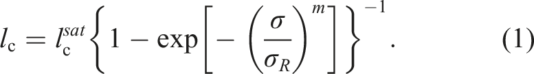
Under uniaxial tensile loading, the dominant and earliest damage mechanism in CMCs is distributed matrix cracking.74–77 In contrast to monolithic ceramics which undergo abrupt, catastrophic failure upon reaching their tensile strength, CMCs exhibit progressive, spatially distributed matrix cracking that underpins their quasi-ductile mechanical response. Matrix cracking initiates when the local tensile stress in the ceramic matrix exceeds its intrinsic matrix cracking strength, a value typically one to two orders of magnitude lower than the fracture strength of the reinforcing fibers. Owing to inherent microstructural heterogeneities, including processing-induced pores, thermally mismatched residual stresses, and spatial variations in fiber–matrix interfacial bond strength, crack nucleation occurs at applied stresses significantly below the composite’s ultimate tensile strength. Initial cracks preferentially form in matrix-rich regions or at localized interfacial flaws such as debonded segments or interphase discontinuities. With increasing load, the number of transverse matrix cracks grows progressively; these cracks propagate perpendicularly to the loading axis and become regularly spaced at intervals of approximately 100–500 µm. Upon reaching a critical strain, crack density asymptotically approaches a saturation limit, beyond which the matrix becomes fully segmented into discrete ligaments bounded by stabilized transverse cracks. Subsequent loading no longer generates new cracks but instead drives crack opening displacement (COD) and interfacial debonding, leading to progressive load transfer from the matrix to the fibers.78–80 Consequently, the tensile stress–strain curve exhibits a distinct inflection point, i.e., the “knee” at first matrix cracking stress, followed by a linear regime with markedly reduced effective modulus. This stiffness degradation reflects the loss of matrix load-carrying capacity across cracked sections, resulting in near-exclusive load bearing by the fibers. The curve remains approximately linear until the onset of fiber fracture, which ultimately governs composite rupture. In summary, matrix cracking in CMCs follows a well-defined sequence: early initiation governed by local stress concentrations and interface properties; progressive multiplication driven by stress redistribution; saturation controlled by fiber spacing and interfacial shear resistance; and post-saturation evolution dominated by interfacial sliding and fiber-dominated deformation. This hierarchical damage process fundamentally transforms an intrinsically brittle ceramic matrix into a structurally robust, damage-tolerant material capable of reliable performance in high-temperature structural applications. Under tensile creep loading at elevated temperatures, the inherent variability in matrix strength gives rise to a stochastic distribution of matrix cracking in CMCs.81–83
The two-parameter Weibull distribution is used to describe the tensile strength of the matrix, and the stress-dependent matrix crack space can be determined using the following equation. • Long cracking, i.e., the matrix crack spacing (lc) exceeds twice the interface slip length (2ls), or lc > 2ls. • Medium cracking, i.e., the matrix crack spacing (lc) lies between ls and 2ls, or ls < lc < 2ls. • Short cracking, i.e., the matrix crack spacing (lc) is less than the interface slip length (ls), or lc < ls.
Time-dependent interface oxidation model and fracture mechanics-based interface debonding model
Under tensile creep stress, pre-existing matrix cracks widen and new cracks nucleate within the matrix due to creep deformation, thereby establishing continuous diffusion pathways for oxygen to penetrate the composite interior.84–86 Once ingress occurs, oxygen preferentially oxidizes the fiber/interphase and, subsequently, the reinforcing fibers. In this analysis, “interphase” refers exclusively to the discrete, engineered material layer deposited between the fiber and the matrix; in contrast, “interface” denotes the sharp physical boundary separating two distinct phases—such as the fiber/interphase, interphase/matrix, or (in the absence of an interphase) fiber/matrix boundary.
The oxidation behavior and its impact on composite integrity are highly dependent on the specific interphase material employed. The most widely used interphase material in SiC/SiC composites is pyrolytic carbon (PyC), which provides the desired weak fiber-matrix bonding and crack-deflection capability but is inherently prone to oxidation at elevated temperatures. An alternative interphase material is boron nitride (BN), which exhibits significantly improved oxidation resistance compared to PyC. However, BN has two important limitations: (i) the oxidation product B2O3 is volatile and evaporates, limiting long-term oxidation protection, and (ii) BN is poorly compatible with nuclear applications due to neutron-induced transmutation issues. Other multilayered interphase architectures, such as (PyC/SiC)n or (BN/SiC)n nanoscale multilayers, have been shown to provide improved oxidation resistance and controlled fiber-matrix interactions. The 2.5D SiC/SiC composite specimens used for experimental validation in this study were fabricated via the chemical vapor infiltration (CVI) method and contain a pyrolytic carbon (PyC) interphase, which is the standard interphase material for this composite system. The oxidation mechanisms discussed in the following sections are therefore directly applicable to this material system, but care should be taken when extrapolating to composites with BN or other interphase materials.
Filipuzzi et al. 87 delineates the three sequential phenomena in carbon interphase oxidation: (i) reaction of oxygen with carbon interphase resulting in pores around the fibers, (ii) diffusion of oxygen and carbon oxides along the pores, and (iii) reaction of oxygen with pore walls leading to silica layer growth on fibers and matrix. Jones et al. 88 directly compares two competing subcritical crack growth mechanisms in SiC/SiC composites: oxidation embrittlement mechanism (OEM) operating at temperatures below about 1073–1223 K, and interphase removal mechanism (IRM) operating at higher temperatures, showing that O2 enhanced crack growth occurs by more than one mechanism depending on experimental conditions. At temperatures of 1073 to 1223 K, the IRM may operate at short times with a transition to the OEM at longer times if the stress is sufficiently low that sample failure does not occur first. Lissart and Lamon 89 discusses how pyrocarbon interphases are prone to oxidation; as interphases are consumed, loads are progressively transferred to fibers, with failure potentially occurring from fiber overloading. In SiC/SiC composites, this oxidation yields a silica (SiO2) scale.90,91 Although this scale initially acts as a diffusion barrier, sustained mechanical stress compromises its integrity—inducing microcracking and spallation—which in turn permits progressive oxidative attack. Hamza et al. 92 developed a coupled multiphysics oxidation and viscoplastic model explicitly investigating the stresses and damage induced by the SiC-silica phase transformation, noting that silica formation and growth kinetics at SiC fiber surfaces generate significant stress fields that contribute to fiber degradation. Hay 93 reports that high growth shear stress was inferred to cause intense dislocation plasticity near the crystalline SiO2–SiC interphase, and that scales formed in the crystalline state were heavily deformed by the growth stress accompanying SiC oxidation volume expansion. The molar volume expansion associated with the SiC → SiO2 conversion (SiC +1.5O2 → SiO2 + CO2) generates compressive residual stresses in the growing oxide scale and associated tensile hoop stresses in the underlying fiber. These stresses can nucleate and propagate microcracks in the silica scale, expose fresh SiC surface to further oxidation, and accelerate overall fiber degradation. This mechanism acts in concert with the load-redistribution effects from interphase removal and can significantly reduce the time-to-failure under sustained loading.94,95
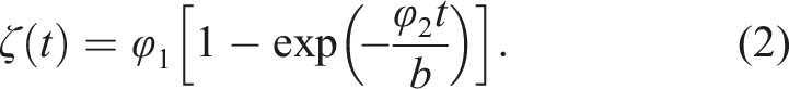
Critically, stress does not merely facilitate physical access for oxidants; it actively accelerates oxidation kinetics through a mechanistically coupled process known as “stress-oxidation coupling.” Specifically, creep-induced crack opening increases reactive surface area, while stress-enhanced ionic transport in the oxide promotes faster scale growth and degradation. As these degradation mechanisms accumulate synergistically, the effective load-bearing cross-section of intact fibers diminishes progressively, culminating in macroscopic failure. In the present analysis, the oxygen reacts with the interphase along the fiber length at a certain rate of dζ/dt, in which ζ is the length of interphase oxidation on each side of the crack. The interface oxidation length is determined by equation (2).
26
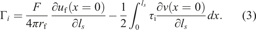
Creep-induced interface debonding denotes the time-dependent, progressive separation of fibers from the surrounding matrix along the fiber/matrix interphase under sustained mechanical loading at elevated temperatures. The shear-lag model integrated with a fracture mechanics–based debonding criterion represents the most widely adopted theoretical framework for analyzing this phenomenon. Within this framework, the shear-lag analysis quantitatively determines the axial stress distribution in the fiber and the corresponding interfacial shear stress distribution along the bonded length. Debonding initiates when the local interfacial shear stress reaches the critical interfacial shear strength; subsequent debond propagation occurs only when the energy release rate at the debond tip attains the interfacial fracture toughness (Γi), satisfying the thermodynamic condition for quasi-static crack growth. The fracture mechanics-based interface debonding criterion is given by equation (3).
96
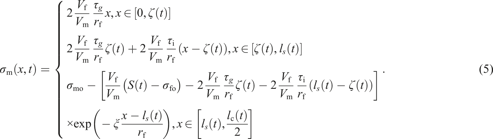
For the composite containing a matrix crack, it is assumed that the matrix is fully fractured across a given crack plane; stress transfer between fiber and matrix occurs exclusively via interfacial shear; and the interface comprises two distinct regions: an intact, frictionally bonded region, and—where oxidation has occurred—a debonded region weakened by oxidation, of length ζ. The fiber axial stress σf (x) and matrix axial stress σm (x) are related by equilibrium and interface shear stress. In the oxidized zone (
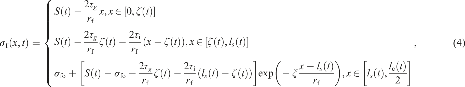
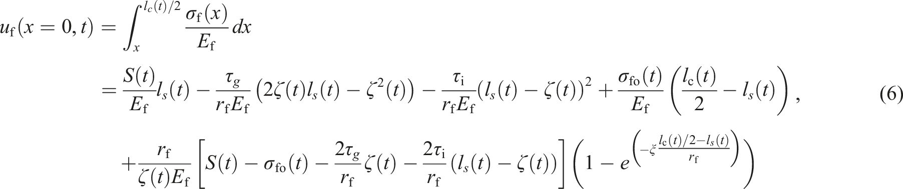
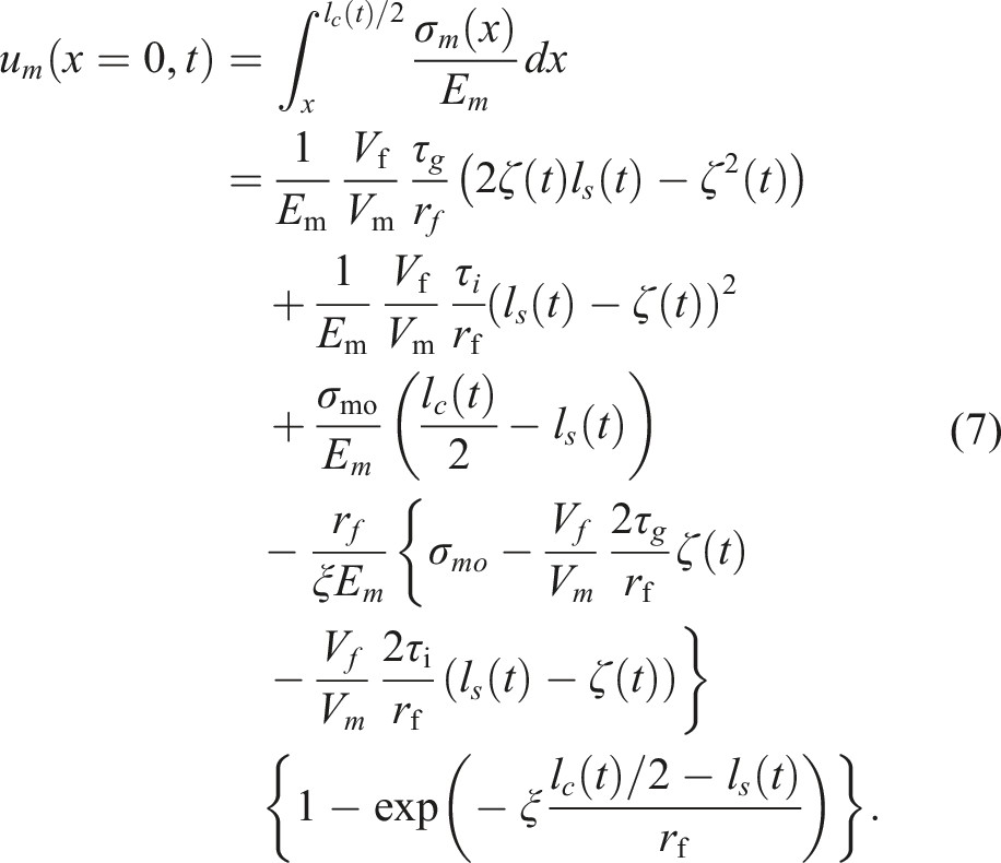
Fiber and matrix axial displacements at the matrix crack plane (x = 0) can be obtained by integrating the fiber or matrix strain from the matrix crack plane to the half of matrix crack spacing, as follows:
The relative displacement between the fiber and the matrix at the matrix crack plane is,
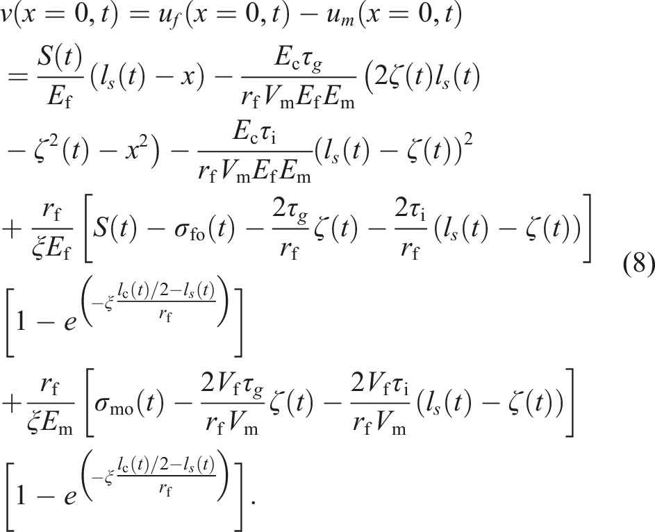
The interface oxidation length ζ enters the displacement calculation through the spatial variation of the interface shear stress. In the region

Global load sharing-based fiber stochastic failure model
Under creep loading at elevated temperatures (e.g., >1000°C for SiC/SiC composites), fiber failure in CMCs proceeds via time-dependent, thermally activated mechanisms—not instantaneous brittle fracture. The global load-sharing (GLS) model constitutes the foundational mechanical assumption for predicting tensile creep rupture in CMCs featuring weak fiber/matrix interfaces.
97
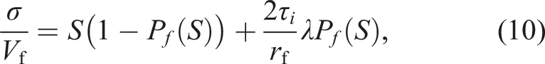
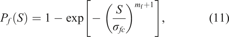
Within this framework, upon fiber fracture, the load previously borne by the failed fiber is instantaneously and uniformly redistributed across all remaining intact fibers in the composite cross-section, thereby precluding localized stress intensification near the break site. It is important to reconcile the weak-interface assumption underlying the GLS model with the possible strengthening effect of silica formation. In the present PyC-interphase SiC/SiC composite, oxidation of the interphase proceeds primarily by carbon burnout, leaving a porous gap rather than a continuous SiO2 bridge. The interface shear strength decreases significantly upon oxidation, as confirmed by push-out tests in the literature.98–100 Therefore, the GLS assumption remains valid for the material and temperature range studied. However, for composites with BN interphase or multilayered coatings where silica bridging is more likely, the interface may strengthen with oxidation, and the use of GLS would require re-evaluation. To quantify statistical fiber strength variability, a two-parameter Weibull distribution is employed; combined with the GLS assumption, it enables analytical derivation of the evolving stress distribution among intact fibers and the progressive accumulation of fiber failures under sustained load.
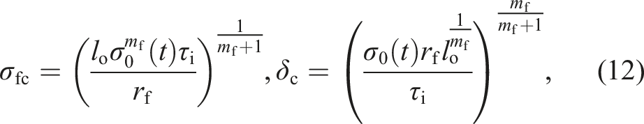
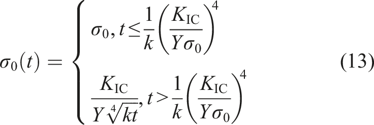
The time-dependent fiber strength σ0 (t) can be determined using equation (13).
25
Microscale creep constitutive model
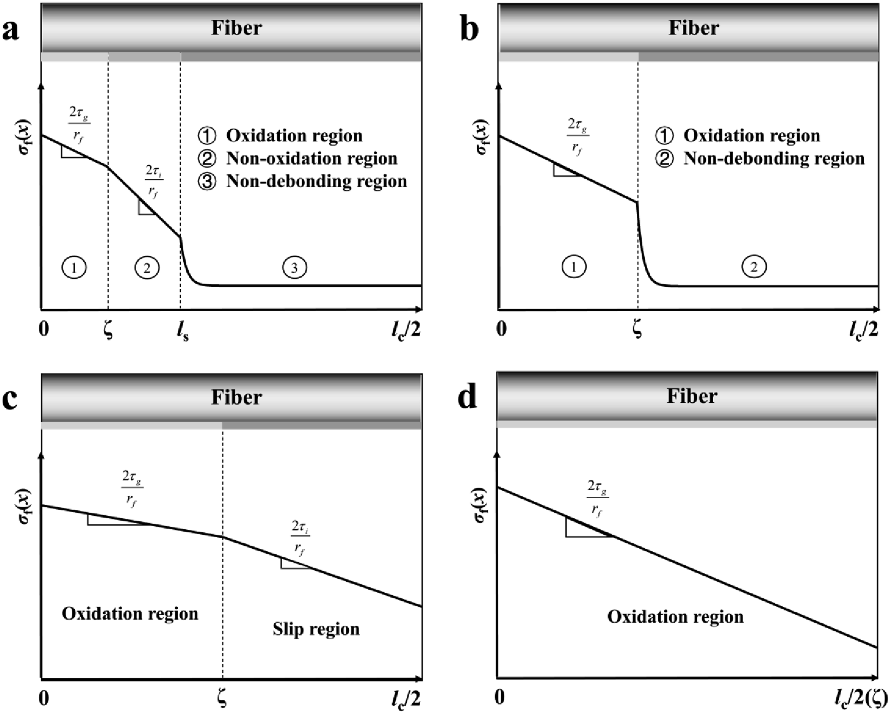
The interactions of the interface oxidation, interface debonding, and matrix cracking affect the creep strain in the composite. To systematically evaluate this effect, six distinct matrix cracking modes as shown in Figure 2 are considered in the analysis, as follows: • Mode I: a long matrix crack, i.e., i.e., lc > 2ls, with the interface oxidation region propagating the partial debonded region, i.e., ζ < ls. • Mode II: a long matrix crack, i.e., lc > 2ls, with the interface oxidation region extending over the entire debonded region, i.e., ζ = ls. • Mode III: a medium crack, i.e., ls < lc < 2ls, with the interface oxidation region propagating the partial debonded region, i.e., ζ < ls. • Mode IV: a medium crack, i.e., ls < lc < 2ls, with the interface oxidation region extending over the entire debonded region, i.e., ζ = ls. • Mode V: a short crack, i.e., lc < ls, with the interface oxidation region propagating the partial debonded region, i.e., ζ < ls. • Mode VI: a short crack, i.e., lc < ls, with the interface oxidation region extending over the entire debonded region, i.e., ζ = ls. Schematic of fiber axial stress distribution for different matrix cracking modes. (a) Mode I for a long matrix crack with partial interface oxidation in the debonding region; (b) mode II for a long matrix crack with complete interface oxidation in the debonding region; (c) mode III or mode V for a mediate or short matrix crack with partial interface oxidation in the slip region; (d) mode IV or VI for a mediate or short matrix crack with complete interface oxidation in the slip region.
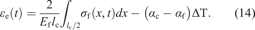
When damage develops within fiber-reinforced CMCs, the composite’s average elastic strain of εe is obtained by integrating the axial strain along the fiber length of σf (x, t), as shown in equation (14).
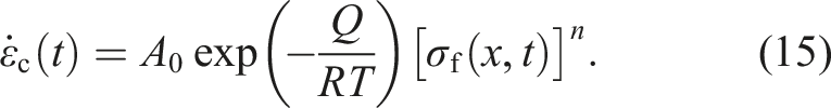
Both fibers and matrix present time-dependent deformation at elevated temperatures. After matrix cracking and fiber/matrix interface debonding, the creep rate of the fibers is determined using equation (15).
In the present model, the composite is assumed to be in the matrix-cracked regime throughout most of the creep life. This is a well-established characteristic of fiber-reinforced CMCs under tensile loading: the matrix fails first by stochastic cracking at relatively low stresses, after which the applied load is carried almost exclusively by the fibers. The characteristic time for matrix stress relaxation via creep is much longer than the time required for matrix cracking under the applied step loads. Even if the matrix were to creep, its contribution to the composite strain would be limited because the cracked matrix carries negligible axial stress. The neglect of matrix creep is valid for the specific material system (2.5D SiC/SiC with PyC interphase) and test conditions (1000–1300°C, stepwise loading where matrix cracking occurs early). For composites with very high matrix cracking stresses, or for loading regimes where the matrix remains intact for extended periods, matrix creep should be included. The total composite’s strain of εt (t) is the sum of the elastic strain and the creep strain.

Although the matrix creep contribution is explicitly set to zero in equation (17), the effect of differential creep between fibers and the cracked matrix is not entirely ignored. It manifests through the progressive relaxation of fiber axial stress as the interface oxidizes and slides, which is fully accounted for in the coupled system of equations for stress transfer. In this sense, the model captures the dominant consequence of creep mismatch – namely, the gradual shedding of load from the fiber to the interface and back – without requiring a separate matrix creep term.
In this section, the microscale stress fields in the fiber for above-mentioned damage modes are first derived and then substituted the fiber axial stress into equations (14) ∼ (17), the composite’s total creep-oxidation strain can be obtained.
Mode I
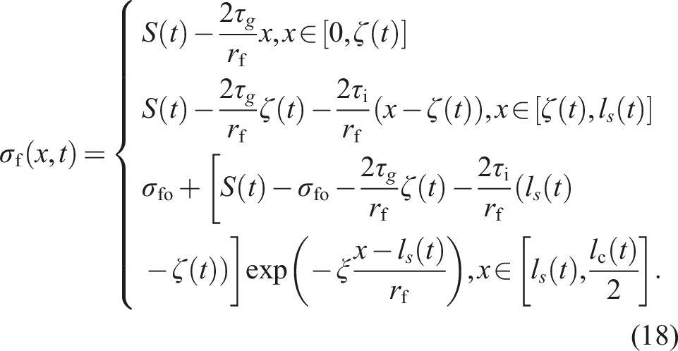
For the damage state of cracking Mode I, interface oxidation propagates over a portion of the debonded interface region associated with a long matrix crack. Within the oxidized interface region, the reduced interfacial shear stress τg governs load transfer between the oxidized fiber and the matrix; in contrast, within the non-oxidized interface region, the original higher interfacial shear stress τi mediates load transfer between the intact fiber and the matrix. The fiber axial stress distribution in the oxidized interface slip region, non-oxidized interface slip region, and non-debonding region are determined by equation (18).
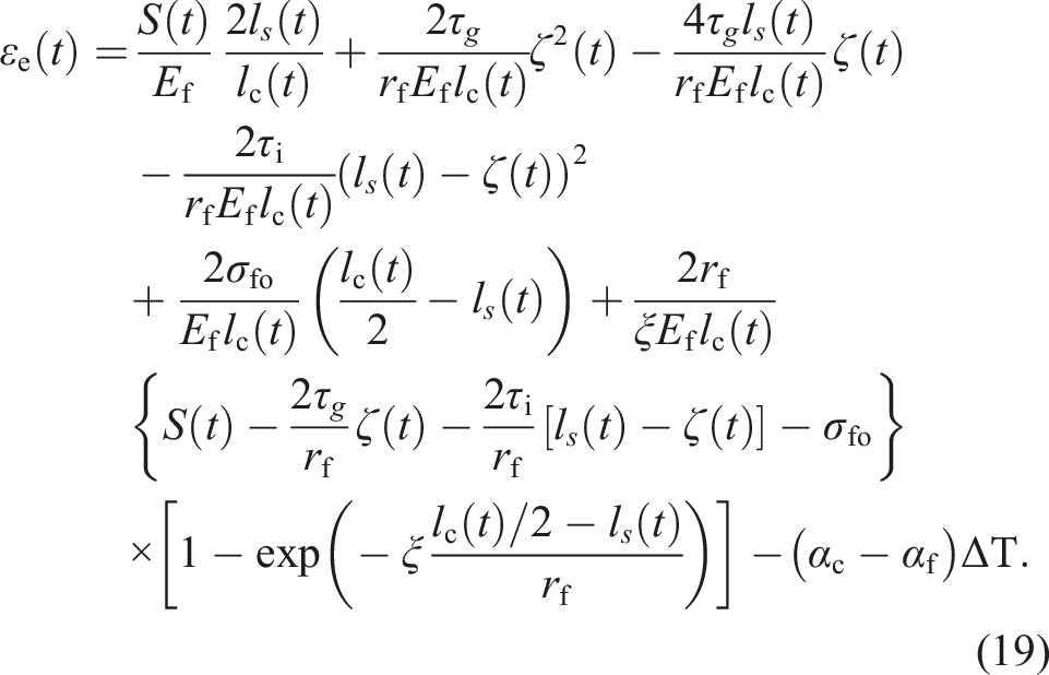
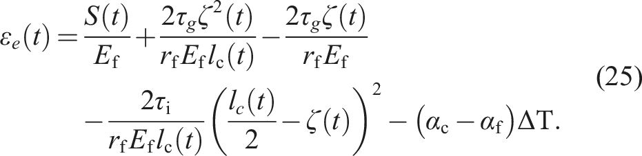
Substituting the time-dependent fiber axial stress in equation (18) into equation (14), the composite’s elastic strain of εe (t) can be determined using the following equation.
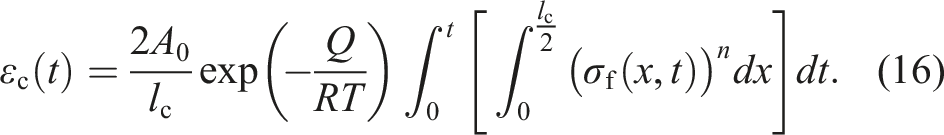
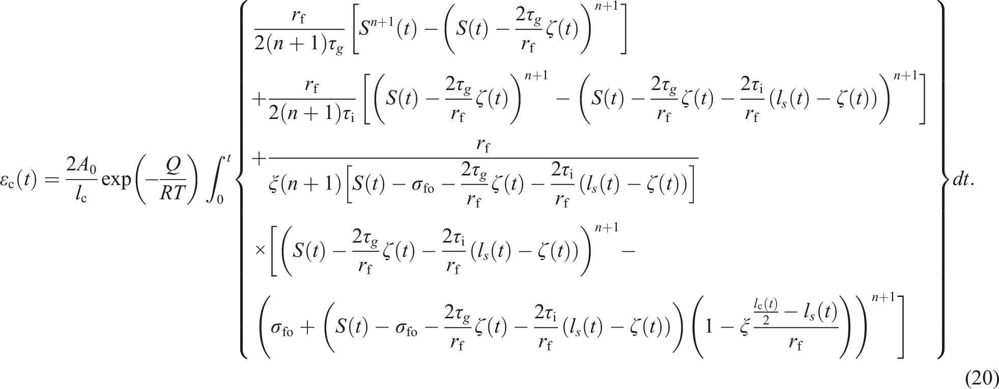
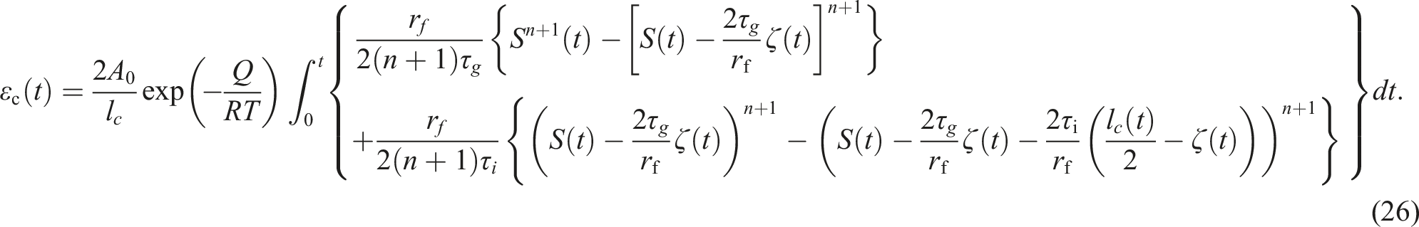
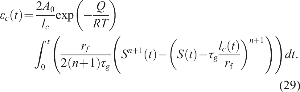
Substituting the time-dependent fiber axial stress in equation (18) into equation (16), the average fiber creep strain of εc (t) can be determined using the following equation.
Mode II
For the damage state of Mode II, interface oxidation propagates to the entire interface debonded region associated with a long matrix crack. Low interface shear stress of τg transfers load between the fiber and the matrix in the oxidized region. Between the matrix crack spacing, the damage region can be divided into the interface oxidation region and the interface bonding region. The fiber axial stress distribution in the oxidized interface slip region, and non-debonding region are determined by equation (21).
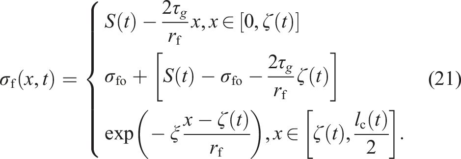
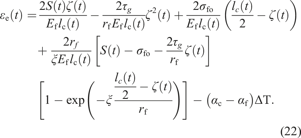
Substituting the time-dependent fiber axial stress in equation (21) into equation (14), the composite’s elastic strain of εe (t) can be determined using the following equation.
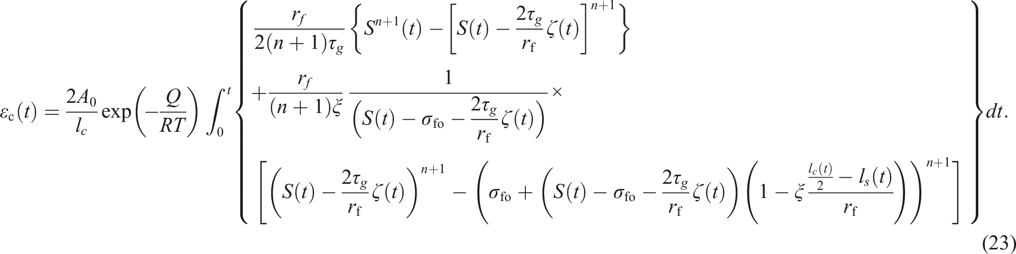
Substituting the time-dependent fiber axial stress in equation (21) into equation (16), the average fiber creep strain of εc (t) can be determined using the following equation.
Mode III & mode V
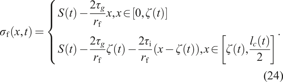
For the damage state of Mode III and Mode V, interface oxidation propagates to the partial interface debonded region associated with a medium matrix crack or a short matrix crack. No bonging region existed between the matrix cracks. The interface oxidation region propagated partial interface slip region. The fiber axial stress distribution in the oxidized interface slip region, and non-oxidized debonded region are determined by equation (24).
Substituting the time-dependent fiber axial stress in equation (24) into equation (14), the composite’s elastic strain of εe (t) can be determined using the following equation.
Substituting the time-dependent fiber axial stress in equation (24) into equation (16), the average fiber creep strain of εc (t) can be determined using the following equation.
Mode IV and mode VI
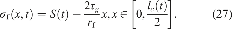
For the damage state of Mode IV and Mode VI, interface oxidation propagates to the entire interface debonded region associated with a medium matrix crack or a short matrix crack. The interface oxidation region occupied the entire matrix crack spacing. The fiber axial stress distribution in the oxidized interface slip region is determined by equation (27).
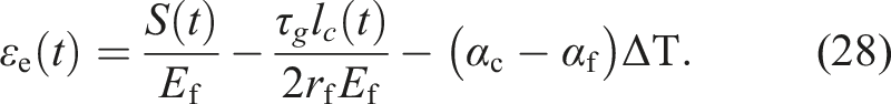
Substituting the time-dependent fiber axial stress in equation (27) into equation (14), the composite’s elastic strain of εe (t) can be determined using the following equation.
Substituting the time-dependent fiber axial stress in equation (27) into equation (16), the average fiber creep strain of εc (t) can be determined using the following equation.
Model validation
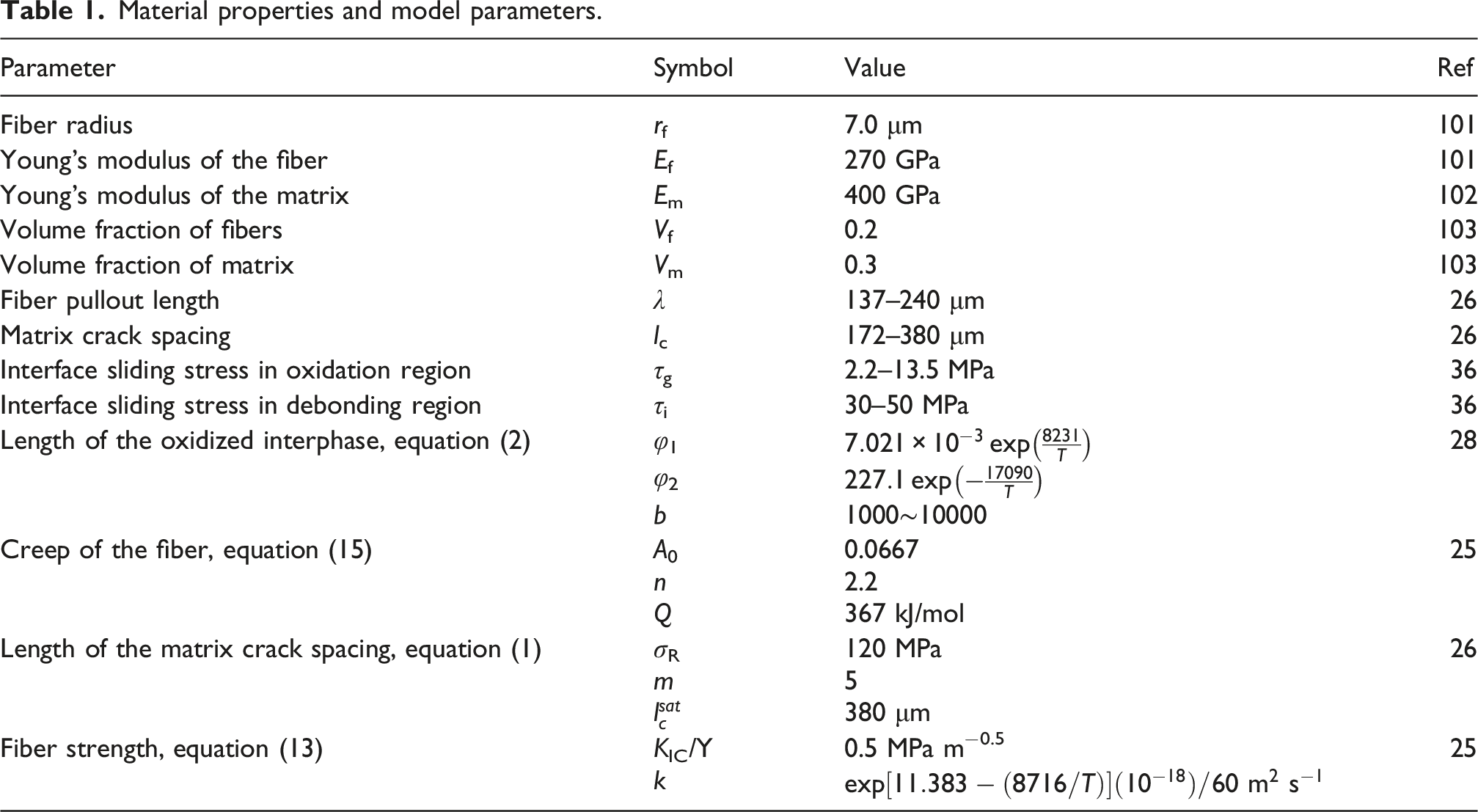
Material properties and model parameters.
Rationale and scope of validation using woven composite data
Optimally, a microscale model should be validated against experimental data from unidirectional (UD) composites, whose fiber architecture directly aligns with the model’s underlying assumptions. However, for the specific material system—2.5D SiC/SiC—and loading conditions—stepwise creep at 1000–1300°C—publicly available experimental datasets with sufficient temporal and thermomechanical resolution (i.e., high-fidelity strain–time histories, precise temperature control records, and fully documented step-load sequences) remain exceptionally scarce. Under these severe thermo-mechanical conditions, the 2.5D woven composite provides the most relevant, experimentally robust, and comprehensively reported dataset currently accessible for this class of ceramic matrix composites.
Accordingly, the validation objective is not to assert point-wise quantitative correspondence, but rather to assess whether the microscale model correctly captures key qualitative and semi-quantitative features: namely, the evolution trends of macroscopic strain, the relative magnitudes of creep rates across load steps, and the parametric sensitivity to temperature and stress. In this sense, the woven composite serves as a stringent benchmark: it tests the model’s ability to reproduce the dominant physical mechanisms—oxidation-assisted interface degradation, fiber creep, and interfacial load redistribution—while explicitly recognizing that weave-specific secondary effects (e.g., tow crimp-induced stress concentrations, inter-tow nesting, and transverse matrix cracking) lie outside the scope of the current formulation.
Key assumptions underpinning the validation approach
Three foundational assumptions enable a physically meaningful comparison between the microscale model predictions and the experimental response of the 2.5D woven composite: (1) Homogenized tow-level response: The 2.5D woven composite is treated as a homogeneous effective medium at the macroscale; however, its overall constitutive behaviour is governed by the mechanical response of individual tows—fiber bundles preferentially aligned with the loading direction. The microscale model, formulated for a single fiber embedded in matrix, is assumed to capture the average tow-level behaviour after appropriate upscaling to account for tow-specific microstructural features, including inter-fiber porosity and local fiber volume fraction. (2) Dominant damage mechanisms are qualitatively consistent: In both UD and 2.5D woven SiC/SiC composites subjected to tensile creep at elevated temperatures (1000–1300°C), the primary time-dependent degradation processes—matrix microcracking, oxidation-assisted interface debonding, fiber creep, and stochastic fiber fracture—are shared. Although the woven architecture introduces geometric complexities (e.g., tow crimp, inter-tow gaps, and transverse reinforcement), these features predominantly influence initial elastic stiffness and local stress heterogeneity; they do not alter the underlying thermo-chemo-mechanical coupling between creep deformation and oxidative degradation. Consequently, the woven composite data remain appropriate for validating the model’s core physical mechanisms. (3) Scale separation enables rigorous homogenization: The characteristic length scale of the weave—defined by the tow diameter (≈0.5–1 mm)—is two orders of magnitude larger than key microstructural features, including the fiber diameter (≈14 µm) and interphase thickness (≈0.5 µm). Under this separation-of-scales condition, a well-established homogenization framework applies: the microscale model captures the effective mechanical response of an individual tow, while the global woven composite is modeled as a periodic arrangement of such tows, with explicit architectural corrections for tow crimp, nesting, and transverse reinforcement.
Mechanisms present in the woven composite but excluded from the microscale model
Three dominant mechanisms inherent to the 2.5D woven architecture are explicitly excluded from the microscale model formulation, as follows: (1) Tow crimp and progressive straightening: Under tensile loading, initially undulated tows undergo progressive straightening, inducing a geometrically nonlinear stress–strain response that deviates fundamentally from the straight-fiber kinematic assumption of the microscale model. While this effect dominates the initial (primary) creep regime, its influence attenuates markedly once tows achieve near-alignment with the loading axis. Accordingly, model validation is explicitly restricted to the secondary and tertiary creep stages—where crimp-induced nonlinearity is negligible—and where the dominant time-dependent mechanisms (interface oxidation, fiber creep, and load redistribution) govern macroscopic behavior. (2) Inter-tow shear and transverse-tow cracking: In the 2.5D architecture, transverse tows are subjected to out-of-plane shear stresses and may undergo matrix cracking or interfacial debonding—mechanisms that introduce additional compliance not represented in the microscale model. These contributions are omitted from the current formulation, leading to a potential underestimation of total macroscopic strain during the early (primary) creep stage. The strong agreement between model predictions and experimental data in the later (secondary and tertiary) creep stages—after transverse cracking has reached saturation—provides empirical support for treating these mechanisms as secondary under the specific thermo-mechanical loading conditions (1000–1300°C, stepwise tensile creep). (3) Local stress concentrations at tow crossovers: The GLS assumption adopted in the microscale model inherently homogenizes these stress gradients by enforcing uniform axial strain across the representative volume element—thus precluding explicit resolution of crossover-induced singularities. However, the developed microscal model is not designed to predict spatially resolved failure initiation sites or the statistical distribution of lifetimes, but rather to estimate the ensemble-averaged time-to-failure under stepwise tensile loading.
Constant loading
Under sustained creep loading at stress levels exceeding the first matrix cracking stress, the elastic and creep strains of the composite are governed by key microstructural parameters, including matrix crack spacing, interfacial debonding and oxidation length, as well as the prevailing matrix cracking mode. This section analyzes the evolution of creep strain in SiC/SiC composites at 1100°C across six distinct cracking modes (Mode I–VI), explicitly linking strain development to fiber failure probability, interfacial debonding extent, and oxidation-induced degradation. Relationship between the damage mode transitions and damage parameters of interface debonding and oxidation ratio is established for the constant loading condition.
Mode I & mode II
At an elevated temperature of 1100°C, the composite’s strain (εt), fiber failure probability (Pf) and interface oxidation ratio (η) of SiC/PyC/SiC composite under σ = 230 MPa for long matrix cracks of lc = 140, 210, and 280 μm are shown in Figure 3. Upon initial loading, the interface debonding length (ls) is about 60 μm, and occupies 85.7, 57.1, and 42.9% of the matrix crack spacing for lc = 140, 210, and 280 μm, respectively. With increasing time of creep loading, the interface oxiation length ζ propagates in the debonding region, leading to the increase of the interface oxidation ratio ( Time-dependent evolution of the composite’s strain (εt), fiber failure probability (Pf) and interface oxidation ratio (η) for mode I (long crack with partial interface oxidation) and mode II (long crack with complete interface oxidation) under σ = 230 MPa. (a) Composite’s strain (εt) and fiber failure probability (Pf) versus time (t) curves; (b) interface oxidation ratio (η) versus time (t) curves.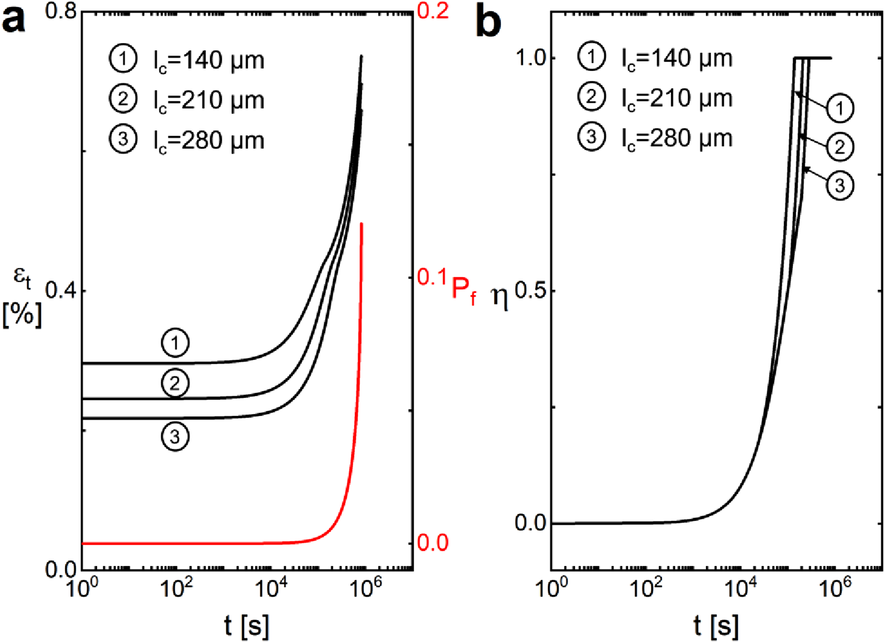
Mode III & mode IV
At an elevated temperature of 1100°C, the composite’s strain (εt), fiber failure probability (Pf) and interface oxidation ratio (η) of SiC/PyC/SiC composite under σ = 230 MPa for mediate matrix cracks of lc = 70, 91, and 112 μm are shown in Figure 4. Upon initial loading, the interface debonding length (ls) is about 60 μm, and equals 0.86, 0.66 and 0.53 times the matrix crack spacing for lc = 70, 91, and 112 μm, respectively. With increasing time of creep loading, the interface oxiation length ζ propagates in the slip region, leading to the increase of the interface oxidation ratio η. The damage state transfers from Mode III (medium crack with paritial interface oxidation) to Mode IV (medium crack with complete interface oxidation) at the critical value of η = 1.0. The characteristic time t* required for the interface oxidation ratio η to reach unity increases with increasing matrix crack spacing; specifically, t* equals 8.5%, 11.0%, and 13.6% of the creep fracture life tf for crack spacings lc of 70, 91, and 112 μm, respectively. The composite’s strain εt at initial loading and at final fracture both decrease with increasing matrix crack spacing, and creep fracture occurs when the fiber failure probability reaches Pf = 12.0%. Time-dependent evolution of the composite’s strain (εt), fiber failure probability (Pf) and interface oxidation ratio (η) for mode III (medium crack with partial interface oxidation) and mode IV (medium crack with complete interface oxidation) under σ = 230 MPa. (a) Composite’s strain (εt) and fiber failure probability (Pf) versus time (t) curves; (b) interface oxidation ratio (η) versus time (t) curves.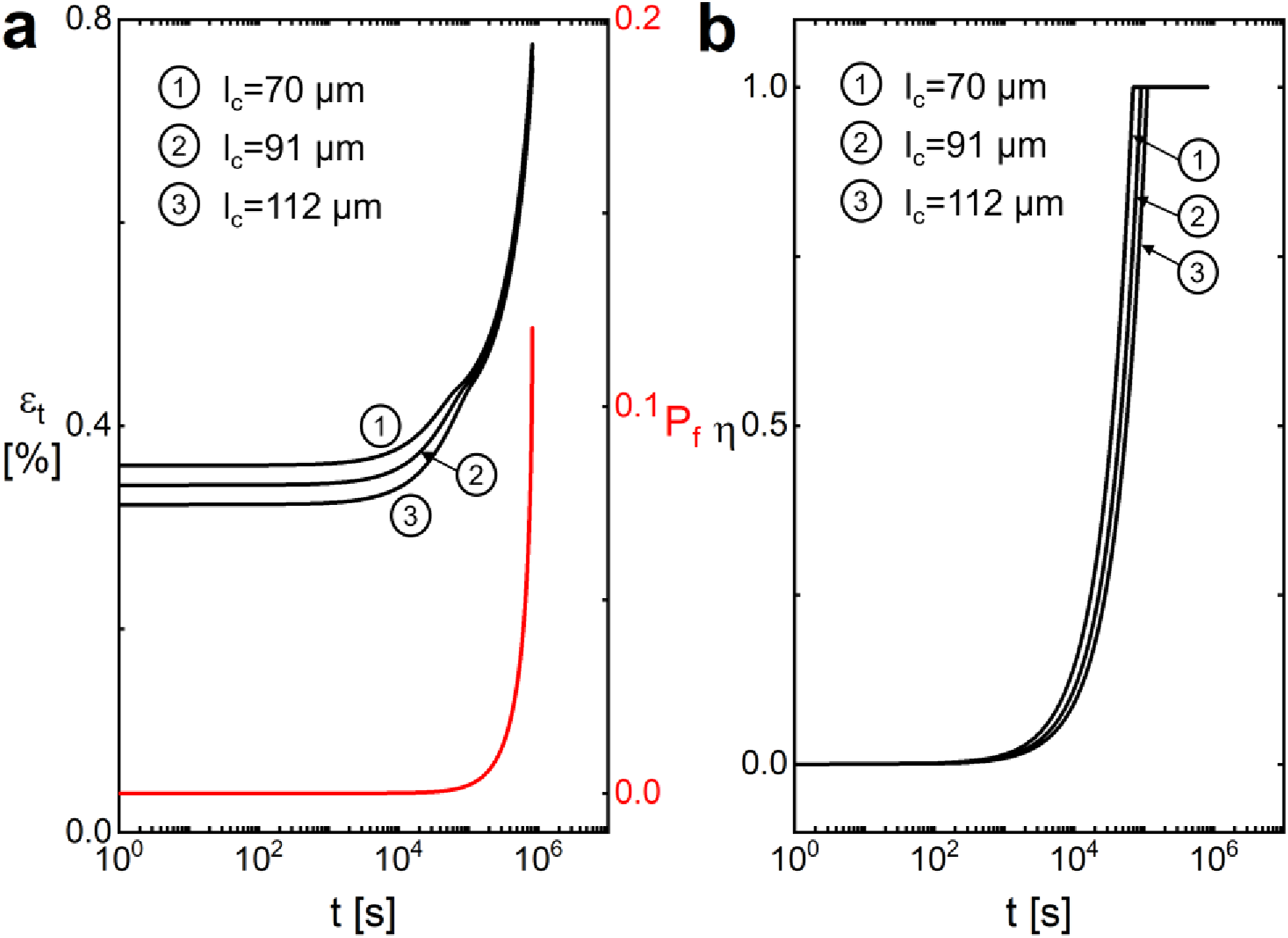
Mode V & mode VI
At an elevated temperature of 1100°C, the composite’s strain (εt), fiber failure probability (Pf) and interface oxidation ratio (η) of SiC/PyC/SiC composite under σ = 230 MPa for short matrix cracks of lc = 20, 30, and 40 μm are shown in Figure 5. Upon initial loading, the interface debonding length (ls) is about 60 μm, and equals 3.0, 2.0 and 1.5 times the matrix crack spacing for lc = 20, 30, and 40 μm, respectively. With increasing time of creep loading, the interface oxiation length ζ propagates in the slip region, leading to the increase of the interface oxidation ratio η. The damage state transfers from Mode V (short crack with paritial interface oxidation) to Mode VI (short crack with complete interface oxidation) at the critical value of η = 1.0. The characteristic time t* required for the interface oxidation ratio η to reach unity increases with increasing matrix crack spacing; specifically, t* equals 2.4%, 3.6%, and 4.8% of the creep fracture life tf for crack spacings lc of 20, 30, and 40 μm, respectively. The composite’s strain εt at initial loading and at final fracture both decrease with increasing matrix crack spacing, and creep fracture occurs when the fiber failure probability reaches Pf = 12.0%. Time-dependent evolution of the composite’s strain (εt), fiber failure probability (Pf) and interface oxidation ratio (η) for mode V (short crack with partial interface oxidation) and mode VI (short crack with complete interface oxidation) under σ = 230 MPa. (a) Composite’s strain (εt) and fiber failure probability (Pf) versus time (t) curves; (b) interface oxidation ratio (η) versus time (t) curves.
Stepwise loading
Under stepwise loading, both the elastic and creep strains of the composite are governed by the applied stress level due to the stress-dependent progression of matrix cracking, interfacial debonding, and fiber failure. This section systematically analyzes how stepwise loading stress level, loading duration, and creep temperature influence the evolution of composite strain, and quantitatively links these variables to fiber failure probability, interfacial debonding and oxidation length. Relationship between the damage mode transitions and damage parameters of interface debonding and oxidation ratio is established for the stepwise loading condition.
Effect of loading level
At an elevated temperature of 1100°C, the composite’s strain (εt), fiber failure probability (Pf), interface debonding ratio ( • Under the SL1 step loading sequence, the damage mode remains to be Mode I (long crack with partial interface debonding and oxidation) upon increasing applied stress level from σ1 = 200 MPa to σ2 = 220 MPa, and transfers to Mode III (mediate crack with partial interface oxidation) upon increasing applied stress level from σ2 = 220 MPa to σ3 = 240 MPa. • Under the SL2 and SL3 step loading sequence, the damage mode remains to be Mode I (long crack with partial interface debonding and oxidation) upon the first step loading, and transfers to Mode V (short crack with partial interface oxidation) upon the second step loading. Time-dependent evolution of the composite’s strain (εt), fiber failure probability (Pf), interface slip ratio (γ) and interface oxidation ratio (η) for different step loading sequences (SL1: σ1 = 200 MPa for t1 = 0 ∼ 10 h → σ2 = 220 MPa for t2 = 10 ∼ 20 h → σ3 = 240 MPa; SL2: σ1 = 200 MPa for t1 = 0 ∼ 10 h → σ2 = 230 MPa for t2 = 10 ∼ 20 h → σ3 = 260 MPa; and SL3: σ1 = 200 MPa for t1 = 0 ∼ 10 h → σ2 = 240 MPa for t2 = 10 ∼ 20 h → σ3 = 280 MPa). (a) Composite’s strain (εt) and fiber failure propabality (Pf) versus time (t) curves; (b) interface slip ratio (γ) and interface oxidation ratio (η) versus time (t) curves.
Effect of loading duration
At an elevated temperature of 1100°C, the composite’s tensile strain (εt), fiber failure probability (Pf), interface debonding ratio ( • Under the SL1 step-loading sequence, the dominant damage mode evolves from Mode I (long crack accompanied by partial interface debonding and oxidation) to Mode III (medium crack with partial interface oxidation) upon increasing the applied stress from σ1 = 200 MPa to σ2 = 220 MPa at t = 20 h; it further transitions to Mode VI (short crack associated with complete interface oxidation) upon subsequent stress elevation from σ2 = 220 MPa to σ3 = 240 MPa at t = 40 h. • Under the SL2 step loading sequence, the damage mode remains to be Mode III (medium crack with partial interface oxidation) upon increasing the applied stress from σ1 = 200 MPa to σ2 = 220 MPa at t = 40 h, and transfers to be Mode VI (short crack associated with complete interface oxidation) upon subsequent stress elevation from σ2 = 220 MPa to σ3 = 240 MPa at t = 60 h. • Under the SL3 step loading sequence, the damage mode remains to be Mode IV(medium crack with complete interface oxidation) upon increasing the applied stress from σ1 = 200 MPa to σ2 = 220 MPa at t = 80 h, and transfers to be Mode VI (short crack associated with complete interface oxidation) upon subsequent stress elevation from σ2 = 220 MPa to σ3 = 240 MPa at t = 100 h. Time-dependent evolution of the composite’s strain (εt), fiber failure probability (Pf), interface slip ratio (γ) and interface oxidation ratio (η) for different step loading sequences SL1 (σ1 = 200 MPa for t1 = 0 ∼ 20 h → σ2 = 220 MPa for t2 = 20 ∼ 40 h → σ3 = 240 MPa), SL2 (σ1 = 200 MPa for t1 = 0 ∼ 40 h → σ2 = 220 MPa for t2 = 40 ∼ 60 h → σ3 = 260 MPa), and SL3 (σ1 = 200 MPa for t1 = 0 ∼ 80 h → σ2 = 220 MPa for t2 = 80 ∼ 100 h → σ3 = 240 MPa). (a) Composite’s strain (εt) and fiber failure propabality (Pf) versus time (t) curves; (b) Interface slip ratio (γ) and interface oxidation ratio (η) versus time (t) curves.
Effect of temperature
The composite’s tensile strain (εt), fiber failure probability (Pf), interface debonding ratio ( • At 1000°C, the damage mode changes from Mode I (long crack with partial interface debonding and oxidation) to Mode III (medium crack with partial interface oxdiation) at the firt step loading from σ1 = 200 MPa to σ2 = 220 MPa, and transfers from Mode III (medium crack with partial interface oxdiation) to Mode VI (short crack with complete interface oxdiation) at the second step loading from σ2 = 220 MPa to σ3 = 240 MPa. • At 1100°C, the damage mode changes from Mode I (long crack with partial interface debonding and oxidation) to Mode III (medium crack with partial interface oxdiation) at the firt step loading from σ1 = 200 MPa to σ2 = 220 MPa, and transfers from Mode IV (medium crack with complete interface oxdiation) to Mode VI (short crack with complete interface oxdiation) at the second step loading from σ2 = 220 MPa to σ3 = 240 MPa. Time-dependent evolution of the composite’s strain (εt), fiber failure probability (Pf), interface slip ratio (γ) and interface oxidation ratio (η) for step loading sequence of σ1 = 200 MPa for t1 = 0 ∼ 30 h → σ2 = 220 MPa for t2 = 30 ∼ 60 h → σ3 = 240 MPa at T = 1000°C and 1100°C. (a) Composite’s strain (εt) and fiber failure propabality (Pf) versus time (t) curves; (b) Interface slip ratio (γ) and interface oxidation ratio (η) versus time (t) curves.
Experimental comparisons
This section presents predictions of the experimental creep strain response under stepwise loading at temperatures ranging from 1000 to 1300°C, using the developed microscale creep constitutive models corresponding to the six matrix cracking modes (Mode I–VI). Concurrently, the evolution of three critical internal damage metrics, fiber failure probability, interfacial debonding ratio, and interfacial oxidation extent, is quantitatively predicted. These predictions collectively establish mechanistic linkages among the total composite creep strain, the applied stepwise stress levels, and the underlying time- and stress-dependent damage processes.
Stepwise loading at 1000°C
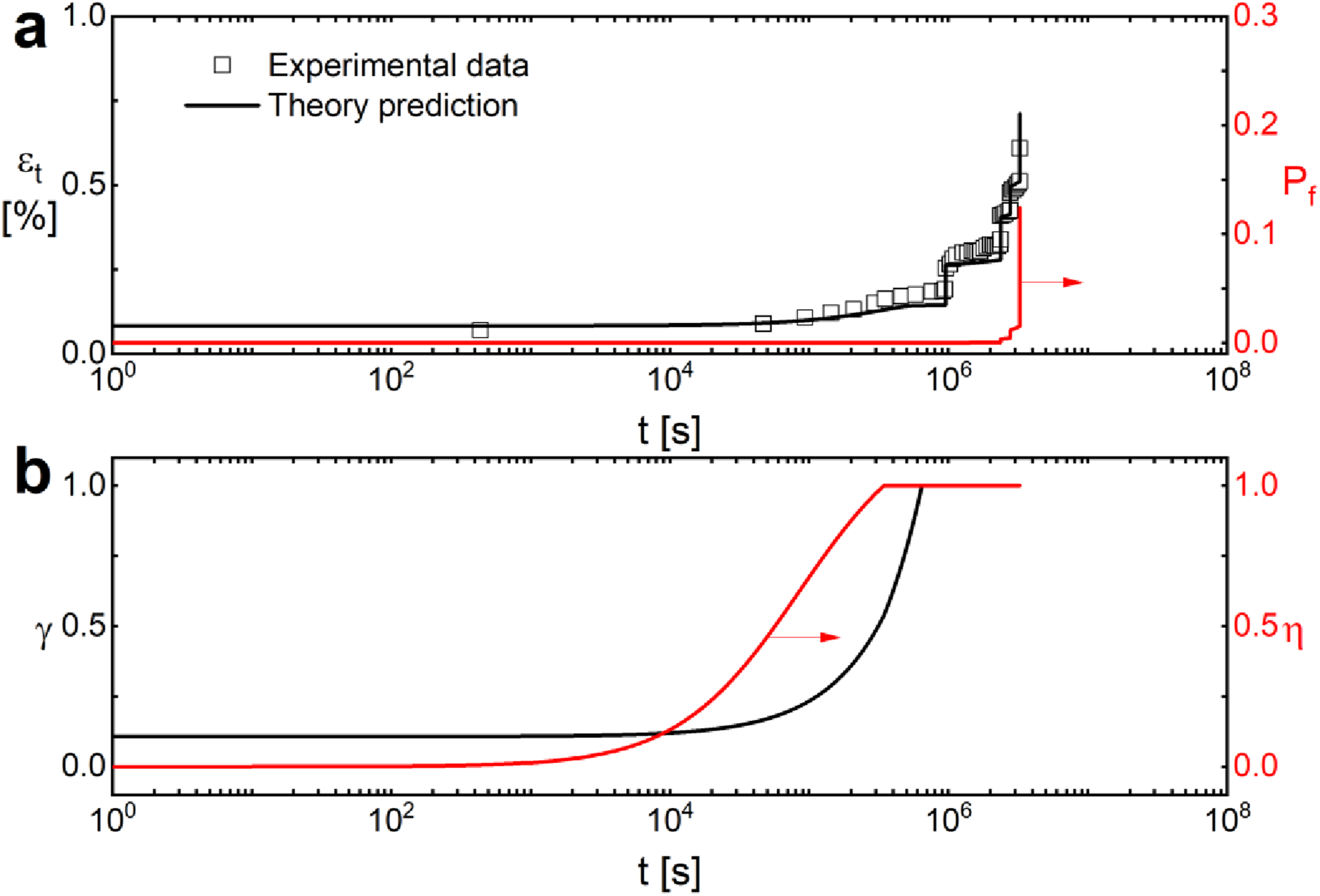
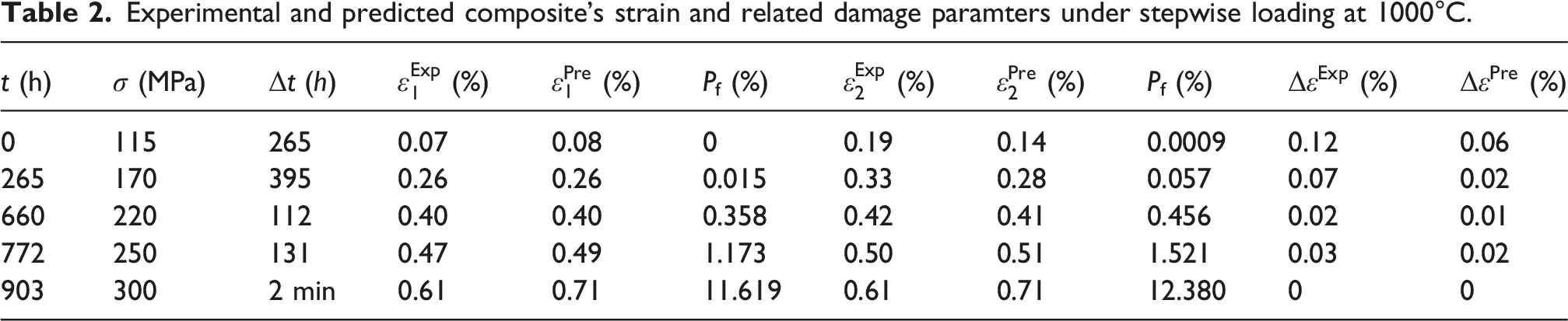
At 1000°C, the experimentally measured and model-predicted total strain (εt), fiber failure probability (Pf), interface debonding ratio (γ), and interface oxidation ratio (η) of the composite under the stepwise loading sequence of σ1 = 115 MPa → σ2 = 170 MPa → σ3 = 220 MPa → σ4 = 250 MPa → σ5 = 300 MPa are presented in Figure 9 and Table 2. Experimental total creep life is 903 h and 2 min, and the predicted composite creep life is 904 h and 43 min. The damage mode evolves from Mode I (a long crack accompanied by partial interface debonding and oxdiation) under the first loading step (σ1 = 115 MPa) to Mode IV (a mediate crack with fully oxidized interface) under the second loading step (σ2 = 170 MPa), and ultimately transitions to Mode VI (a short crack with fully oxidized interface) under the fifth loading step (σ5 = 300 MPa). • Upon initial loading to σ1 = 115 MPa for a duration of Δt = 265 h, the experimental measured initial strain is • Under the second loading step of σ2 = 170 MPa for a duration of Δt = 395 h, the experimental measured initial strain is • Under the third loading step of σ3 = 220 MPa for a duration of Δt = 112 h, the experimental measured initial strain is • Under the fourth loading step of σ4 = 250 MPa for a duration of Δt = 131 h, the experimental measured initial strain is • Upon loading to the final stress level of σ5 = 300 MPa, experimental creep fracture of the composite occurs after Δt = 2.0 min, corresponding to a fracture strain of 0.61%; in contrast, the model prediction yields a fracture strain of 0.71% at a longer duration of 1 h 46 min. Experimental and predicted composite’s total strain (εt), fiber failure probability (Pf), interface debonding ratio (γ) and interface oxidation ratio (η) of SiC/SiC composite at 1000°C under stepwise loading. (a) Experimental and predicted composite’s strain (εt) and fiber failure propabality (Pf) versus time (t) curves; (b) Interface slip ratio (γ) and interface oxidation ratio (η) versus time (t) curves. Experimental and predicted composite’s strain and related damage paramters under stepwise loading at 1000°C.
Stepwise loading at 1100°C
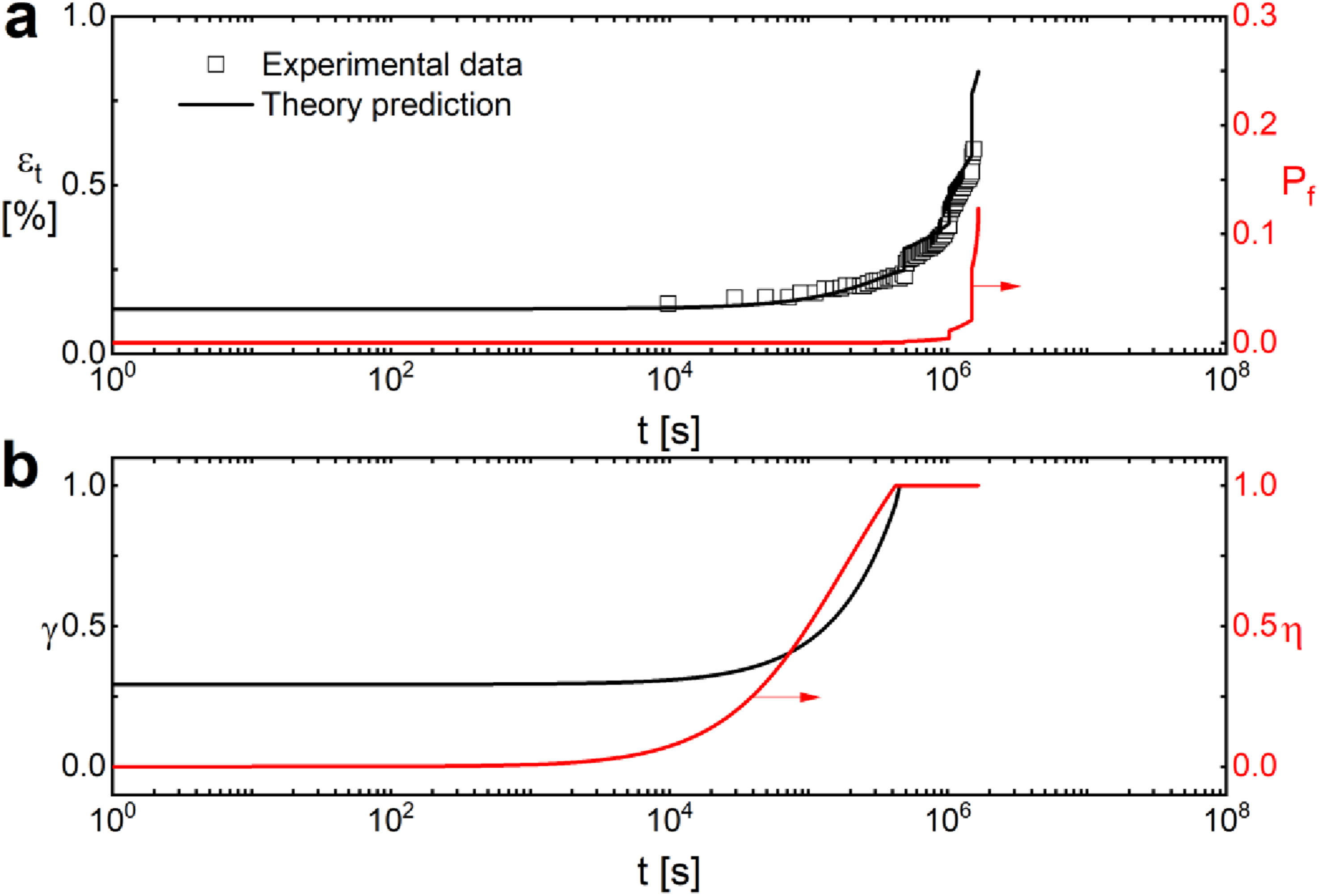
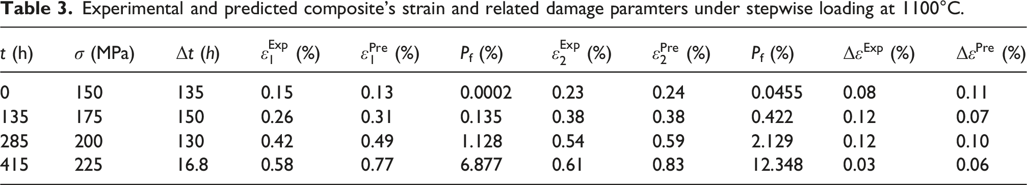
At 1100°C, the experimentally measured and model-predicted total strain (εt), fiber failure probability (Pf), interface debonding ratio (γ), and interface oxidation ratio (η) of the composite under the stepwise loading sequence of σ1 = 150 MPa → σ2 = 175 MPa → σ3 = 200 MPa → σ4 = 225 MPa are presented in Figure 10 and Table 3. Experimental total creep life is 431.8 h, and the predicted composite creep life is 462.2 h. The damage mode evolves from Mode I (a long crack accompanied by partial interface debonding and oxdiation) under the first loading step (σ1 = 150 MPa) to Mode IV (a mediate crack with fully oxidized interface) under the second loading step (σ2 = 175 MPa), and ultimately transitions to Mode VI (a short crack with fully oxidized interface) under the fifth loading step (σ4 = 225 MPa). • Upon initial loading to σ1 = 150 MPa for a duration of Δt = 135 h, the experimental measured initial strain is • Under the second loading step of σ2 = 175 MPa for a duration of Δt = 150 h, the experimental measured initial strain is • Under the third loading step of σ3 = 200 MPa for a duration of Δt = 130 h, the experimental measured initial strain is • Upon loading to the final stress level of σ5 = 225 MPa, experimental creep fracture of the composite occurs after Δt = 16.8 h, corresponding to a fracture strain of 0.58%; in contrast, the model prediction yields a fracture strain of 0.83% at a longer duration of 47.2 h. Experimental and predicted composite’s total strain (εt), fiber failure probability (Pf), interface debonding ratio (γ) and interface oxidation ratio (η) of SiC/SiC composite at 1100°C under stepwise loading. (a) Experimental and predicted composite’s strain (εt) and fiber failure propabality (Pf) versus time (t) curves; (b) interface slip ratio (γ) and interface oxidation ratio (η) versus time (t) curves. Experimental and predicted composite’s strain and related damage paramters under stepwise loading at 1100°C.
Stepwise loading at 1300°C
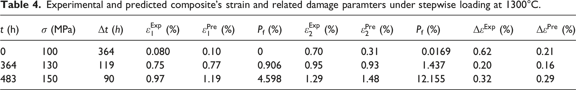
At 1300°C, the experimentally measured and model-predicted total strain (εt), fiber failure probability (Pf), interface debonding ratio (γ), and interface oxidation ratio (η) of the composite under the stepwise loading sequence of σ1 = 100 MPa → σ2 = 130 MPa → σ3 = 150 MPa are presented in Figure 11 and Table 4. Experimental total creep life is 573 h, and the predicted composite creep life is 628.2 h. The damage mode evolves from Mode I (a long crack accompanied by partial interface debonding and oxdiation) under the first loading step (σ1 = 100 MPa) to Mode IV (a mediate crack with fully oxidized interface) under the second loading step (σ2 = 130 MPa), and ultimately transitions to Mode VI (a short crack with fully oxidized interface) under the fifth loading step (σ3 = 150 MPa). • Upon initial loading to σ1 = 100 MPa for a duration of Δt = 364 h, the experimental measured initial strain is • Under the second loading step of σ2 = 130 MPa for a duration of Δt = 119 h, the experimental measured initial strain is • Upon loading to the final stress level of σ3 = 150 MPa, experimental creep fracture of the composite occurs after Δt = 90 h, corresponding to a fracture strain of 1.29%; in contrast, the model prediction yields a fracture strain of 1.48% at a longer duration of 145.2 h. Experimental and predicted composite’s total strain (εt), fiber failure probability (Pf), interface debonding ratio (γ) and interface oxidation ratio (η) of SiC/SiC composite at 1300°C under stepwise loading. (a) Experimental and predicted composite’s strain (εt) and fiber failure propabality (Pf) versus time (t) curves; (b) Interface slip ratio (γ) and interface oxidation ratio (η) versus time (t) curves. Experimental and predicted composite’s strain and related damage paramters under stepwise loading at 1300°C.
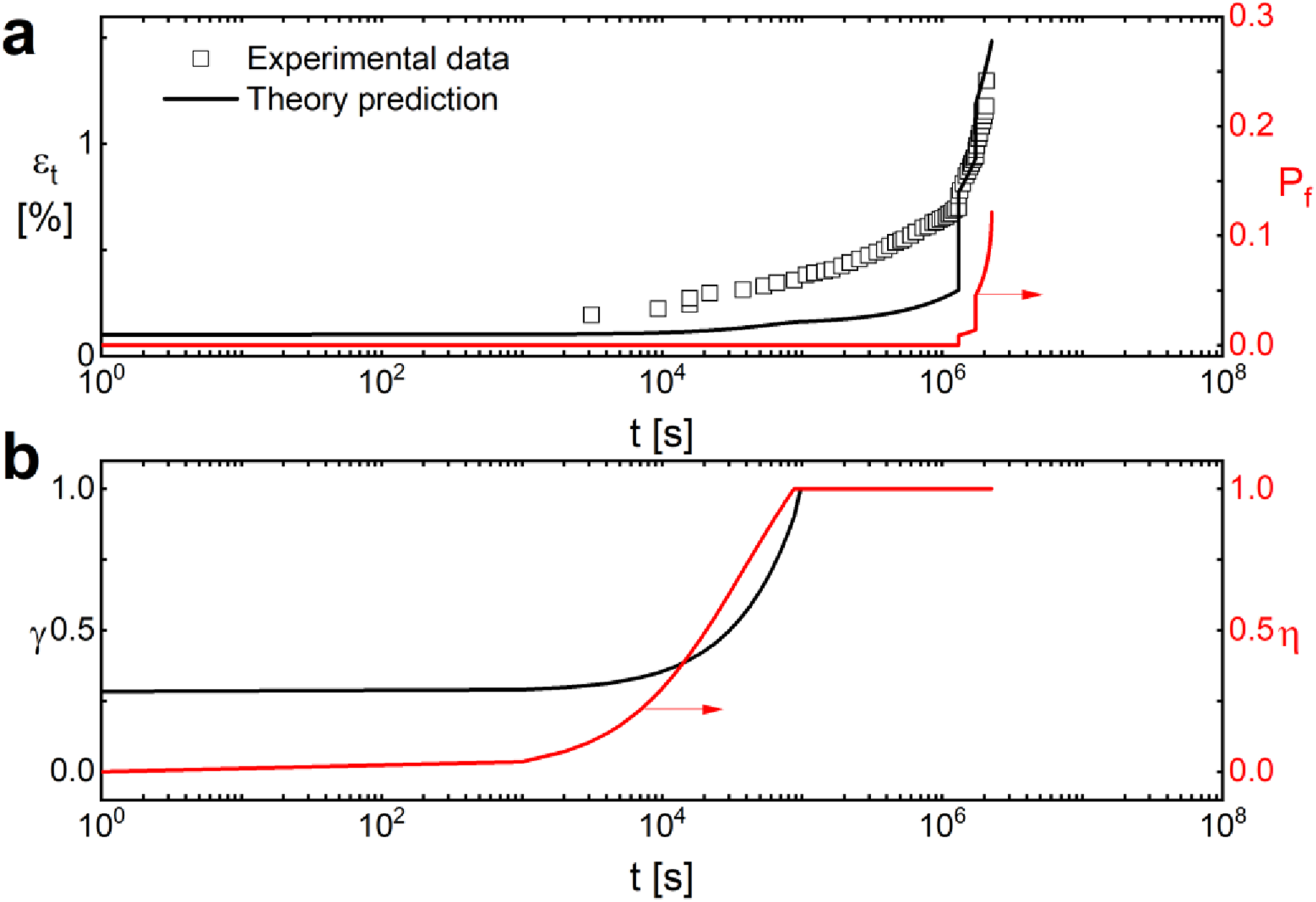
At 1300°C, the model underpredicts the measured total strain. This suggests that additional thermally activated mechanisms, such as possible active oxidation, or matrix creep, become significant at this temperature. These mechanisms are not included in the current formulation.
Discrepancy analysis at 1300°C and model limitations at high temperatures
At 1300°C, compared to 1000°C and 1100°C, several thermally activated processes become significantly more pronounced: (1) Active oxidation and gas phase transport: At very high temperatures (above ∼1200°C in some environments), SiC can undergo active oxidation (formation of gaseous SiO instead of solid SiO2), which completely changes the oxidation kinetics and damage morphology. If active oxidation occurs locally, it would accelerate material loss and strain accumulation far beyond the model’s predictions. (2) Matrix creep contribution becomes non-negligible: While matrix creep was neglected in equation (17) (justified for lower temperatures), at 1300°C the SiC matrix itself may creep, especially in the cracked matrix fragments that are still subjected to compressive or shear stresses. This would add an extra strain component not included in the model.
Model modification to improve predictive accuracy at 1300°C
Optimizing predictive accuracy at 1300°C necessitated two targeted modifications, detailed below: (1) Active oxidation criterion: Add a switch based on oxygen partial pressure and temperature to determine whether passive or active oxidation occurs. If active oxidation is identified, the model should switch to a linear, much faster recession rate. (2) Matrix creep addition: For temperatures above a threshold (e.g., 1200°C), include a separate matrix creep term in equation (17), even in the cracked regime. The matrix stress can be estimated from the shear-lag model, and an appropriate creep law (e.g., Norton power law) can be added.
Summary and conclusions
The objectives of this study were: (1) to develop a microscale creep strain model for fiber-reinforced CMCs under stepwise loading at elevated temperatures, explicitly incorporating interphase and fiber oxidation; (2) to quantify the evolution of interface debonding length and fiber fracture fraction across six matrix cracking configurations (Modes I–VI); and (3) to validate the model against experimental creep data for 2.5D SiC/SiC composites at 1000°C, 1100°C, and 1300°C.
A unified constitutive framework was established that integrates four creep-induced damage mechanisms – stochastic matrix cracking, time-dependent interface oxidation, stress–oxidation-coupled interface debonding, and load-redistribution-mediated stochastic fiber failure – tailored to six distinct matrix cracking configurations (Modes I–VI).
The model quantitatively predicts that under stepwise loading, higher step stress levels increase composite strain and reduce fracture strain/creep life by promoting fiber fracture, interfacial debonding, and interface oxidation. Prolonged dwell conditions shift the dominant damage mechanism from stress-controlled cracking to time-dependent interfacial degradation (debonding and oxidation), while increasing creep temperature further elevates composite strain via thermally activated fiber fracture and debonding.
Model predictions for the 2.5D SiC/SiC composite agree well with experimental creep strain data at 1000°C, 1100°C, and 1300°C. The model serves as a foundational building block for hierarchical multiscale frameworks, enabling long-term creep life prediction of CMC components (e.g., turbine vanes, combustor liners) and integration with probabilistic damage criteria and digital twin implementations.
The validation against 2.5D woven composite experiments is performed under the assumption that the dominant creep-oxidation mechanisms are similar to those in a unidirectional tow and that weave-specific effects (crimp, transverse cracking) are secondary or can be lumped into effective parameters. Recognizing these limitations, future work will focus on extending the current microscale model to explicitly account for weave architecture. Specifically, a new multiscale model will be developed that incorporates tow crimp geometry, inter-tow shear interactions, and transverse tow cracking as additional damage mechanisms. The effective parameter lumping will be replaced by explicit submodels for each weave-specific effect, enabling more accurate predictions for woven composites.
Footnotes
Acknowledgements
The author also wishes to thank the editor and two anonymous reviewers for their helpful comments on an earlier version of the paper.
Declaration of conflicting interests
The author declared no potential conflicts of interest with respect to the research, authorship, and/or publication of this article.
Data Availability Statement
The data used to support the findings of this study are available from the paper.