
Abstract
Perforation damage usually occurs in honeycomb sandwich structures, and to restore mechanical properties, the double-sided repair is required for damaged areas. Although it is convenient to directly bond external patches on the structure, the stiffness difference between the patch and original structure easily causes the interface delamination or secondary stress concentration. The scarf repair better restores the continuity of the original structure, but the removal of more materials leads to a larger damage range. The additional layer introduction regulates the stress distribution at the interface and enhances the bonding strength, but the repair effect is affected by the thickness, edge length, and ply angle of the additional layer. To improve this situation, a novel repair method that integrates the scarf repair with an additional layer optimization is proposed, and the influences on the bending and compression performance as well as the failure behaviors are studied for honeycomb sandwich structures with perforation damage. The 3D Hashin failure criterion is introduced to predict the damage initiation and propagation process of composite materials under different stress states, and the finite element models are established for the intact structure and the scarf-repaired structures with and without optimized additional layers. The response surface methodology combined with the Abaqus/Explicit module is adopted to optimize the side length, thickness, and carbon fiber ply angle of the additional layer. The mechanical properties and failure behaviors before and after repair are obtained through three-point bending and compression tests as well as finite element analysis. The results indicate that the double-sided repair with optimized additional layers effectively alleviates the stress concentration at the connection between the original structure and patches, and the experimental load-bearing, deformation, and energy absorption abilities increase by 38.5%, 20.6%, and 76.7% for bending as well as 18.6%, 24%, and 48.8% for compression, respectively.
Keywords
Introduction
Composite honeycomb sandwich structures have special properties such as lightweight, high specific strength and stiffness, strong fatigue resistance, and low thermal conductivity, which are widely used in the control console surface, wing leading, trailing edge fairing of aircrafts and the fairing of engines.1–3 However, such structure is susceptible to external impacts during manufacturing and service. Different impact energies make panel-core debond, face sheet crack, honeycomb core crush, and perforation damage occur, thereby causing a decrease in the overall structure performance.4,5 Among them, the probability of perforation damage significantly increases under high-speed collision, fall, or strong mechanical vibration conditions. Hence, it is necessary to find a suitable repair method to restore the mechanical properties of the perforation-damaged structure. 6
The external patch repair directly bonds the patch to the damaged area, and does not remove the damaged material, which quickly restores the impact and fatigue resistance of the perforation-damaged structure.7,8 Many scholars have made some progress in using the external patch to repair honeycomb core sandwich composite panels with perforation damage. Li et al. 9 studied the effect of external patch shape on perforation-damaged honeycomb sandwich structures, and found that the square patch had better repair effect. Yala et al. 10 studied the influences of patch size and ply angle on the load-bearing strength of double-sided repaired honeycomb sandwich structures, and determined the optimal patch parameters. Mao et al. 11 studied the effects of the patch lap lengths and stacking sequences on the ultimate failure load and shear strength of double-sided repaired honeycomb sandwich structures, and further optimized the geometric parameters of the patch. Ivanez et al. 12 performed the double-sided patch repair on honeycomb sandwich structure laminates with perforation damage, and analyzed the impact response and contact load under low-speed impact before and after repair. Raju et al. 13 repaired the perforation-damaged honeycomb sandwich structure by external patches, and conducted four-point bending tests to analyze the flexural strength and edgewise compression strength of undamaged, impact-damaged, and repaired specimens. The above researches indicate that the external patch repair quickly restores the mechanical properties of honeycomb sandwich structures with perforation damage, and makes repaired structures to bear high loads. However, this repair method significantly increases the weight and thickness and results in poor surface flatness for the repaired structure.
The scarf repair effectively reduces the negative impact of external patch repair, and is applied in perforation-damaged honeycomb sandwich structures. Ghazali et al. 14 applied the scarf repair on the honeycomb sandwich structures with perforation damage, and studied the mechanical behavior of the pristine structure, damaged structure, and repaired structure under edge compression loads. Tie et al. 15 reasonably designed the patch radius, thickness, and off-axis angle of double-sided scarf repair on honeycomb sandwich structures. Ramantani et al. 16 studied the effects of overlapping repair and scarf repair on the bending performance of double-sided repaired honeycomb sandwich structures, and evaluated the length and patch thickness of overlap repair and the angle of scarf repair in terms of stress analysis and strength prediction to derive design guidelines for sandwich structure repair. Zhang et al. 17 analyzed the shear performance of honeycomb sandwich structures before and after double-sided scarf repair based on load-displacement and shear stress-strain curves. Ji et al. 18 proposed a composite patching and bonding repair process for metal panels with perforation damage in aluminum honeycomb sandwich structures. Ricardo et al. 19 analyzed the fracture behaviors of double-sided scarf-repaired honeycomb/carbon-epoxy sandwich panels under edgewise compression and three-point bending loading, and considered the repair angle of 10° in damaged skins. The above researches mainly analyze the influences of the thickness, length, ply angle, and repair angle of a scarf repair patch on the mechanical properties of honeycomb sandwich structures with perforation damage. However, the connection between the patch and the original structure may introduce new stress concentration points, thereby leading to early damage for the double-sided repair structures.
In view of the advantages and disadvantages of external patch repair and scarf repair, some scholars have proposed to introduce the external patch as additional layers when performing a scarf repair on perforation-damaged honeycomb sandwich structures. Wu et al. 8 studied the damage tolerance of scarf and stepped-lap joints (repairs) under quasi-static loading for honeycomb sandwich structures, and improved the damage tolerance of both joints by attaching composite doubler reinforcement. Zhang et al. 20 performed the double-sided scarf repair on honeycomb sandwich structures and bonded additional layers on the outer surface, and studied the effects of the repair angle and patch stacking sequence on damage evolution and ultimate strength under compression loads. Arikan et al. 21 used different materials and patch types to perform the double-sided scarf repair on honeycomb sandwich structures, then adhered an additional layer on the outer surface of repair patches, and subsequently conducted three-point bending tests to obtain the repair materials and patch types with high efficiency and good performance. The above researches use the additional layer to improve the strength and load transfer of honeycomb sandwich structures with double-sided scarf repair, thereby alleviating the stress concentration in connection areas between the patch and original structure. However, the additional layer has not been optimized, resulting in faster crack propagation and debonding. And with the additional layer thickness increasing, the air resistance coefficient of the overall structure also significantly increases.
Taken together, a new method integrating the additional layer optimization into the conventional scarf repair is proposed to improve the bending and compression performance of honeycomb sandwich structures with perforation damage. The finite element models of the intact structure and the repaired structures with and without optimized additional layers are first established based on the 3D Hashin failure criterion. Then, the optimal design of the additional layer is conducted by the response surface methodology. The bending and compression experiments, as well as the numerical simulation are finally performed on perforation-damaged honeycomb sandwich structures before and after the scarf repair with and without optimized additional layers.
Finite element modeling and quasi-static analysis of perforation-damaged honeycomb sandwich structures before and after the scarf repair with and without optimized additional layers
Double-sided scarf repair with additional layers
The scarf repair method is adopted to repair the damaged parts of upper and lower panels and core of the honeycomb sandwich structure with perforation damage, and two square additional layers with side length L and thickness H are added on the outer surfaces of the repaired structure, as shown in Figure 1(a). The lower panel has two simply supported constraints with a span of m, and s is the distance between ends and constraints. The bending performance test of sandwich structures should comply with the provisions of the ASTM C393/C393 M standard. That is, the width of the sandwich structure, W, is greater than or equal to twice the thickness T, and W is greater than or equal to three times the thickness of the honeycomb core, a, and the length of the sandwich structure, U, is equal to m plus 50 mm, where, U = 150 mm, W = 50 mm, T = 11 mm, a = 10 mm. The side length of the honeycomb core cell is 3 mm, and the single-cell wall thickness is 0.08 mm. The thickness of upper and lower panels, h, is 0.5 mm. Four layers of T300/7901 unidirectional carbon/epoxy prepreg are symmetrically laid up in a [0/90]s sequence. Reference 16 shows that the optimal scarf angle α is 3.819°, and the top repair radius r and the bottom repair radius Perforation-damaged honeycomb sandwich structure after the scarf repair with additional layers.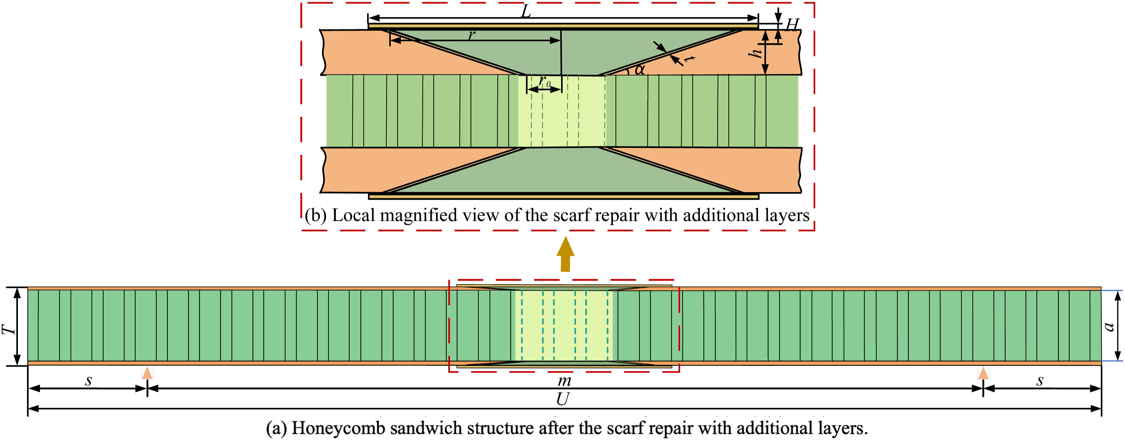
Damage failure model
The progressive damage model accurately captures the process of material from initial microscopic damage to macroscopic damage, and is adopted to dynamically simulate the ultimate failure behavior and progressive damage of composite laminates when subjected to external forces. The 3D Hashin failure criterion including fiber tension, fiber compression, matrix tension, and matrix compression is suitable to complex stress states, distinguishing failure modes, and refining failure modes, and serves as a criterion for determining initial failure in composite laminates. 22 Hence, the 3D Hashin failure criterion is combined with the progressive damage model to effectively simulate the entire process from the onset of damage to the ultimate failure for composite materials. According to Ref. 29, the user-defined material subroutine (VUMAT) within the Abaqus/Explicit framework is adopted to implement the progressive damage model that integrates the 3D Hashin failure criterion and energy-based softening law, effectively capturing the nonlinear shear response and energy dissipation. Among them, four damage initiation criteria are expressed according to Ref. 23:
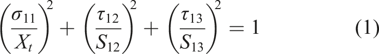
When σ11 ≥ 0, the fiber tensile damage initiation criterion is
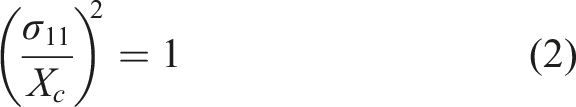
When σ11 < 0, the fiber compression damage initiation criterion is
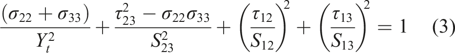
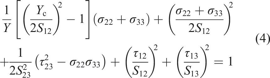
When σ22+σ33 ≥ 0, the matrix tensile damage initiation criterion is
When σ22+σ33 < 0, the matrix compression damage initiation criterion is
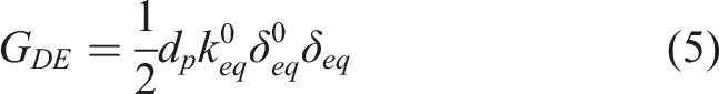
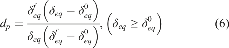
According to Ref. 30, the subsequent damage evolution is governed by an energy-based softening criterion. The dissipated energy
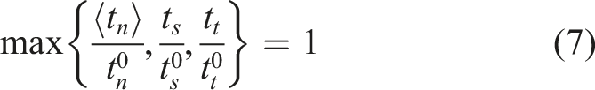
According to Ref. 19, the delamination failure in the interface area and the damage within adhesive layers are simulated using the bilinear Cohesive Zone Model, that is, embedding zero-thickness cohesive elements between adjacent layers in composite panels. The traction-separation law defines the initial linear elastic behavior of the Cohesive element. The maximum stress criterion assumes that the damage begins when the maximum contact stress ratio reaches 1.0, and its expression is as follows:
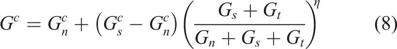
According to Ref. 26, the energy-based criterion is adopted to control the progressive degradation and ultimate failure of the Cohesive element. For mixed-mode loading, complete separation occurs when the dissipated energy reaches the critical energy release rate of the interface. The mixed-mode critical energy release rate is defined by the Benzeggagh-Kenane criterion, And its expression is as follows:
Parametric modeling and dynamic analysis settings
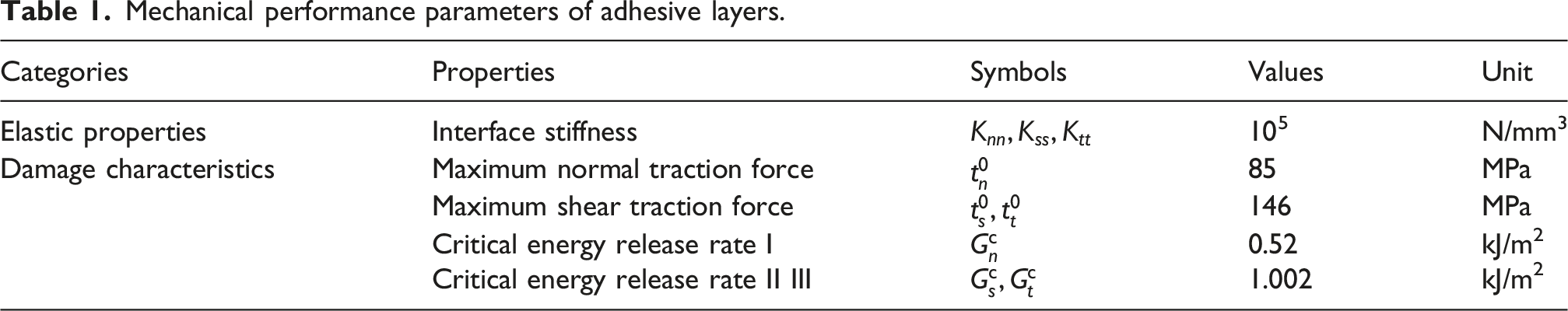
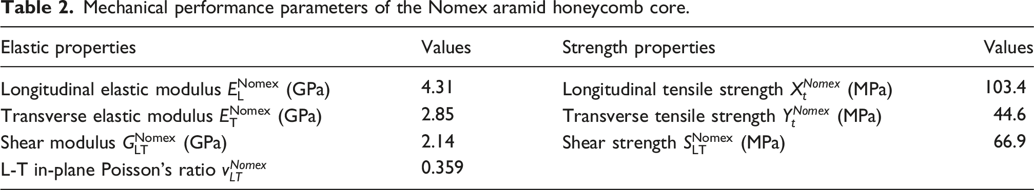
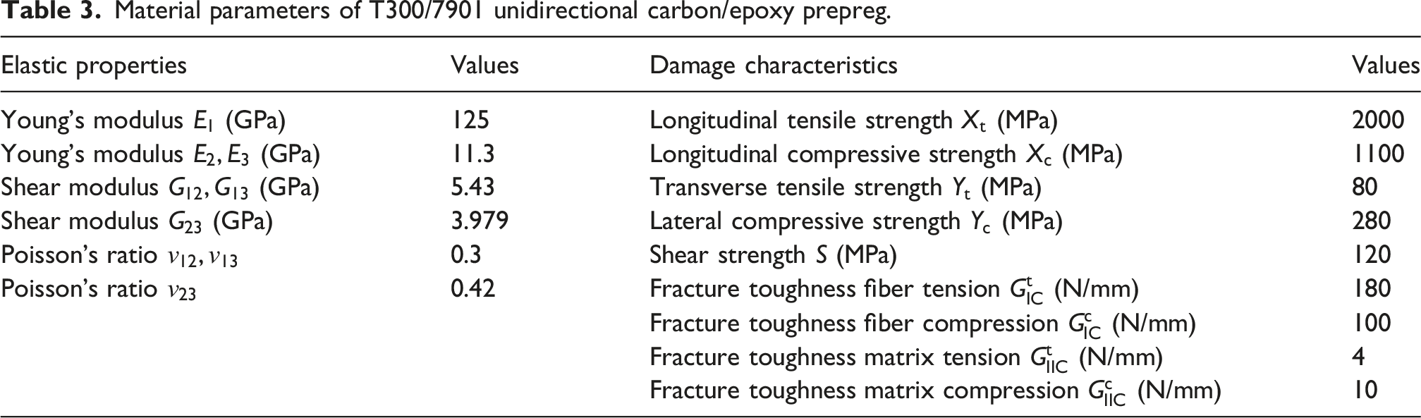
The Abaqus software is used to establish the finite element models for perforation-damaged honeycomb sandwich structures after scarf repair with and without optimized additional layers. These models have the same geometric dimensions and ply parameters as those described above, and half of the model is shown in Figure 2(a). The solid element is used to establish upper and lower panels, patches, and additional layers, and the shell element is used to establish the honeycomb core. According to Ref. 24, the mechanical performance parameters of adhesive layers and Nomex aramid honeycomb core are shown in Table 1 and Table 2. The T300/7901 unidirectional carbon/epoxy prepreg is used to prepare the CFRP laminates, patches, and additional layers. The ply angle of patches is designed to match that of repaired areas. The material parameters of T300/7901 unidirectional carbon/epoxy prepreg are from Refs. 20 and 24, as shown in Table 3. Finite element model of the perforation-damaged honeycomb sandwich structure after the scarf repair with additional layers. Mechanical performance parameters of adhesive layers. Mechanical performance parameters of the Nomex aramid honeycomb core. Material parameters of T300/7901 unidirectional carbon/epoxy prepreg.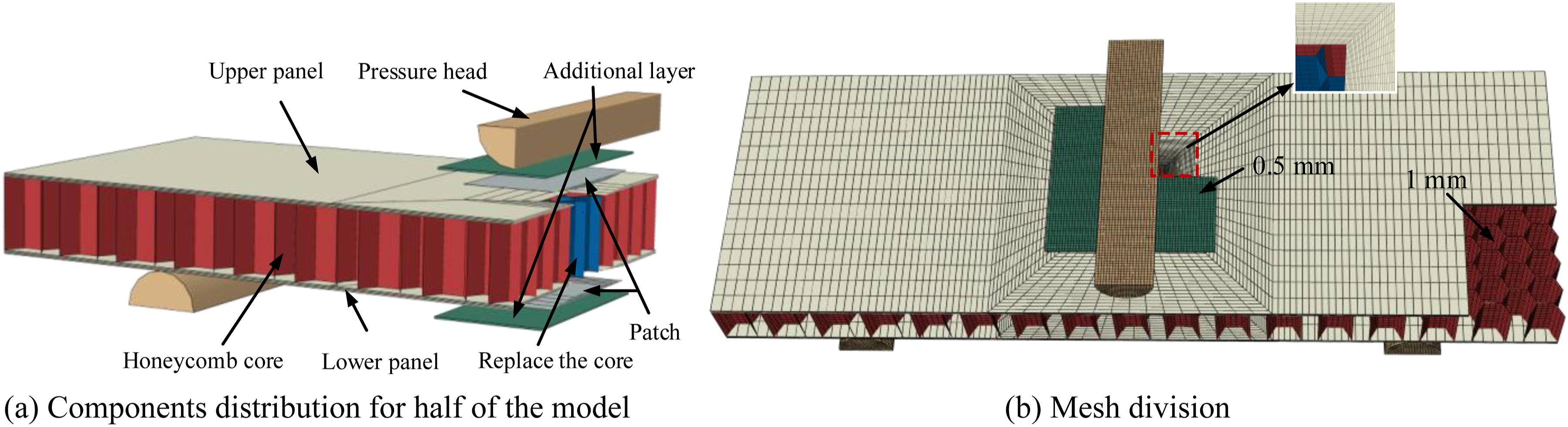
The parametrical geometric models of all parts are obtained by the .rpy file, and the Python language is adopted to integrate them. The failure criteria are defined for the core and composite laminates so as to prevent the distortion of the adhesive layer, and rigid bodies are adopted for the upper pressure head and lower supports. According to Ref. 12, the friction behaviors and complex contact among panels, core, patches, additional layers, pressure head, and supports are simulated using the explicit dynamic analysis. The core and panels are bound through the “Tie” constraint. The surface-to-surface contact areas among repaired panels, patches, and additional layers are set as viscous contact. The contact attributes are set as follows: the hard contact and penalty function are used to define the normal behavior and tangential behavior, respectively, and the friction coefficient is 0.3. The boundary conditions are set as follows: the degree of freedom along the U3 direction is released and a downward moment is applied for the pressure head, and two supports are fully constrained. According to Ref. 28, an explicit solver is employed to handle the complex contact and material degradation, and the loading rate is controlled to keep the kinetic-to-internal energy ratio below 5% throughout the simulation, thereby ensuring quasi-static conditions in the explicit dynamic analysis.
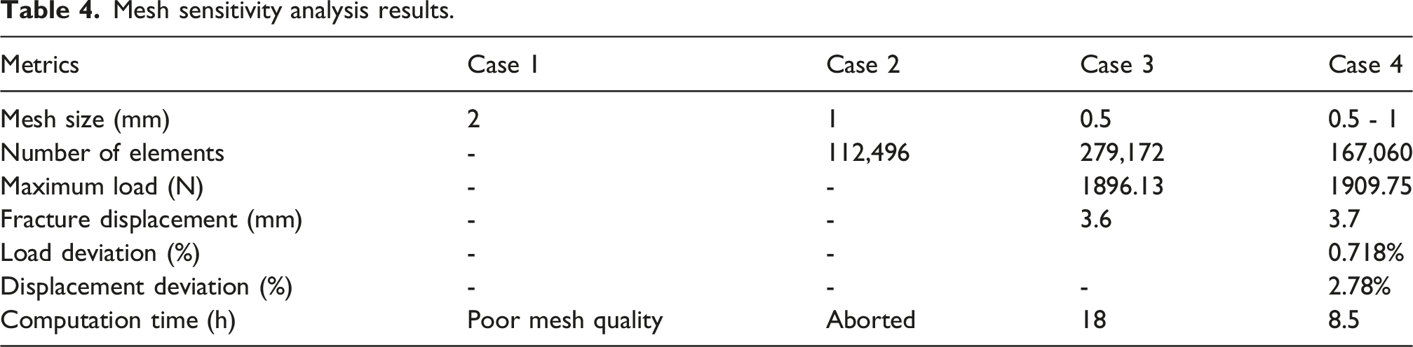
Mesh sensitivity analysis results.
Additional layer parameter optimization and result analysis
Optimization method
Two additional layers are attached to the scarf-repaired honeycomb sandwich structure with perforation damage, which not only enhances the load-bearing ability of the repaired structure, but it also increases the quality and volume. Hence, an optimization model is established to optimize ply angles and geometric parameters of additional layers as follows: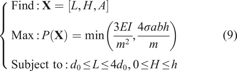
In order to optimize the parameters of the additional layer for scarf-repaired honeycomb sandwich structures with perforation damage, it is necessary to obtain the response surface surrogate model by constructing a design matrix. The accuracy of the model is determined by the difference between the predicted and adjusted values of the complex correlation coefficient R2 in the analysis of variance. Among them, R2 ranges from 0 to 1, and the predicted and adjusted values are represented by
Result analysis
Design matrix for optimizing additional layer parameters.
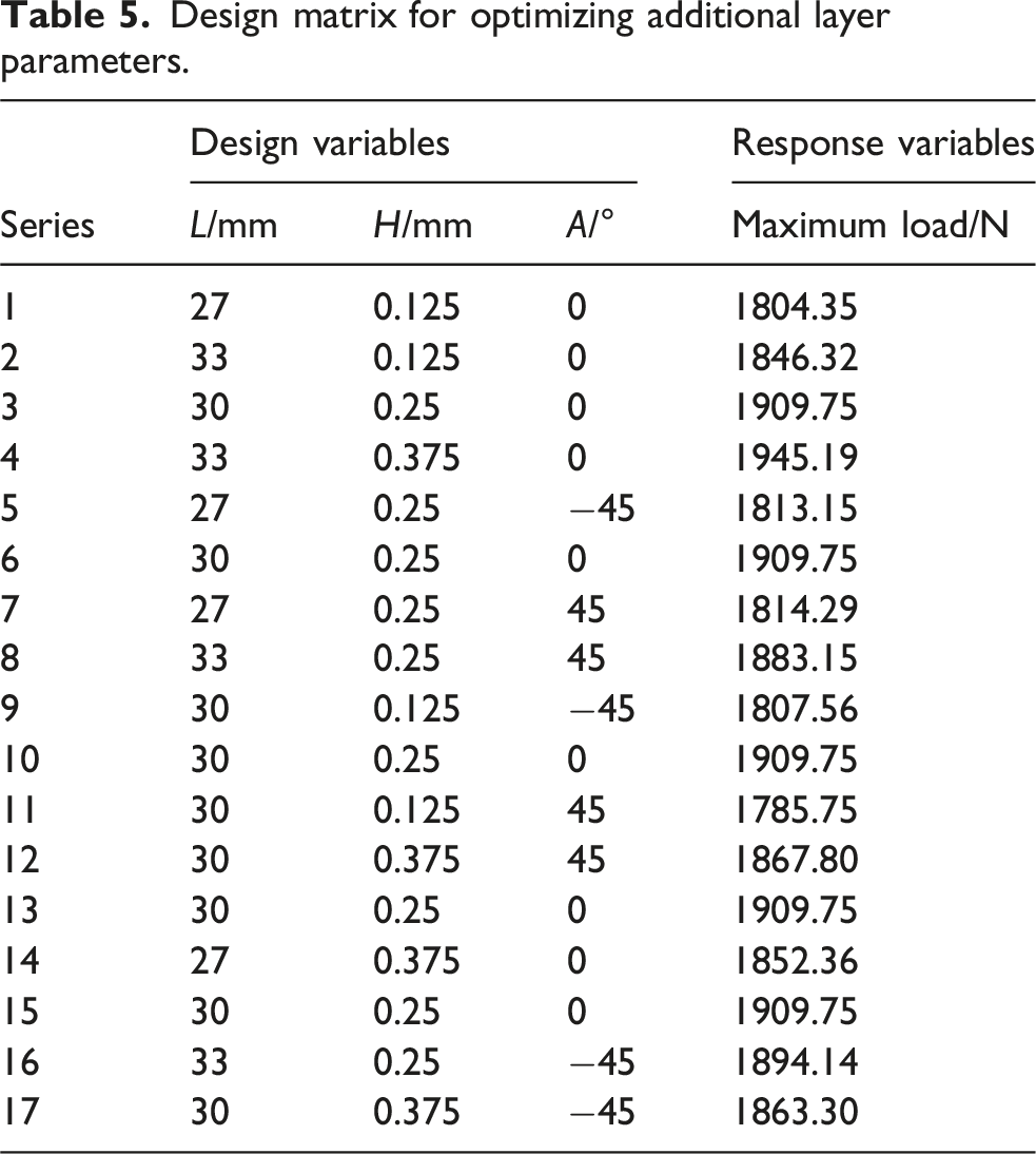
The response surface surrogate model is obtained by fitting a quadratic polynomial based on the data in Table 5, which takes the additional layer parameters as design variables and the maximum load of the scarf-repaired honeycomb sandwich structure with perforation damage as the response variable: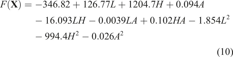
According to Ref. 25 and equation (10), the values of Scatter plot of predicted values versus simulated values.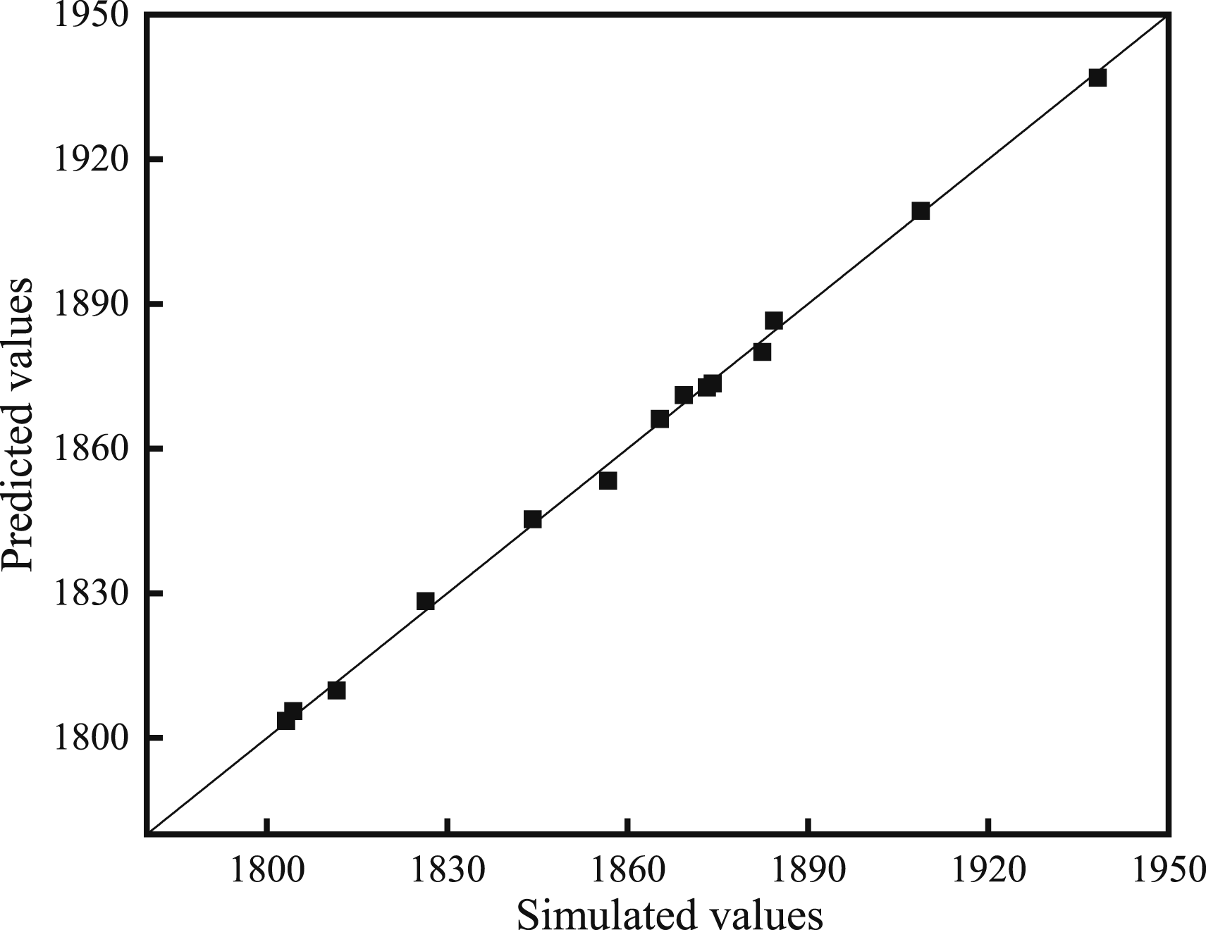
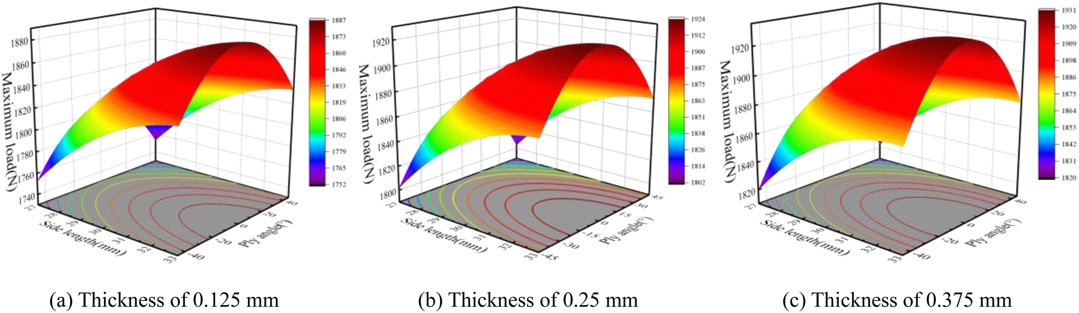
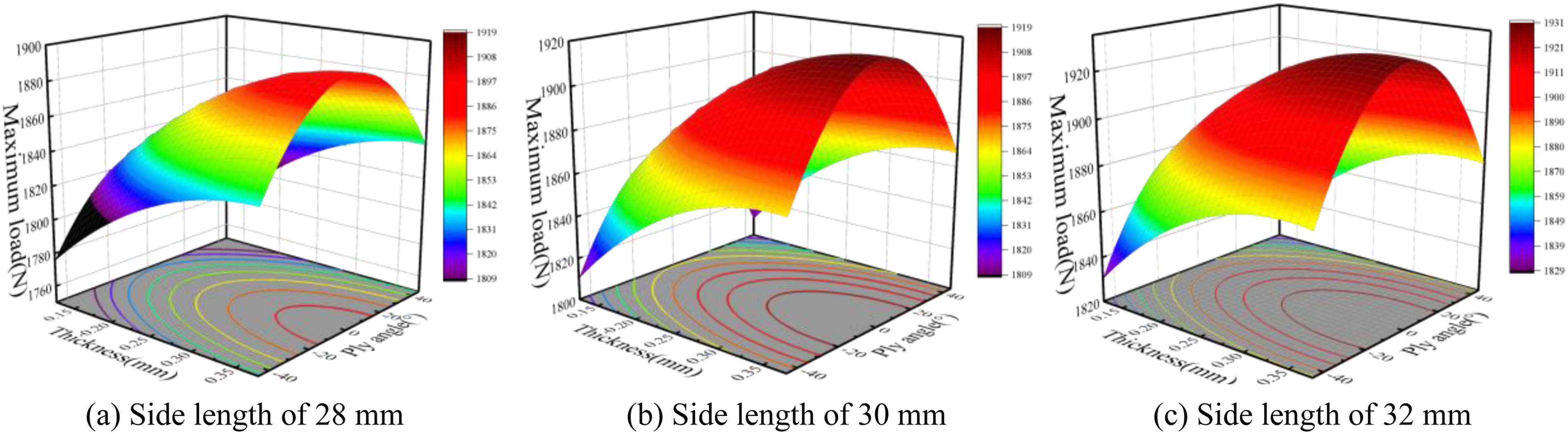
According to the constructed response surface surrogate model, 3D response surface graphs are drawn under the condition of fixing one design variable, as shown in Figures 4–6. In Figure 4, when the ply angle is −45°, 0°, and 45°, the load that the honeycomb structure withstands shows a nonlinear increasing trend with increasing the side length L. Specifically, the maximum load increases more rapidly when the side length L is less than 30 mm, whereas this upward trend slows down after exceeding 30 mm. The maximum load also shows a nonlinear increasing trend with increasing the thickness H. Specifically, the maximum load increases more rapidly when the thickness H is less than 0.25 mm, whereas this upward trend slows down after exceeding 0.25 mm. In Figure 5, when the thickness is 0.125 mm, 0.25 mm, and 0.375 mm, the maximum load shows a nonlinear increasing trend with increasing the side length L. Specifically, the maximum load increases more rapidly when the side length L is less than 30 mm, whereas this upward trend slows down after exceeding 30 mm. The maximum load shows a trend of first increasing and then decreasing with the increase of the ply angle A, and reaches maximum when the ply angle is 0°. In Figure 6, when the side length is 28 mm, 30 mm, and 32 mm, the maximum load shows a trend of first increasing and then decreasing with the increase of the ply angle A, and reaches maximum when the ply angle is 0°. The maximum load shows a nonlinear increasing trend with increasing the thickness H. Specifically, the maximum load increases more rapidly when the thickness H is less than 0.25 mm, whereas this upward trend slows down after exceeding 0.25 mm. In summary, when the side length L reaches a certain size, the performance improvement effect of the repaired structure is significantly weakened. If the thickness H of the additional layer is too large, it will cause the surface of the repaired structure to be too abrupt and increase the resistance of the repaired structure in the air. Hence, the optimal ply angle, thickness, and side length of the additional layer are 0°, 0.25 mm, and 30 mm for scarf-repaired honeycomb sandwich structures with perforation damage, respectively. 3D response surface plots for different values of ply angle. 3D response surface plots for different values of additional layer thickness. 3D response surface plots for different values of additional layer side length.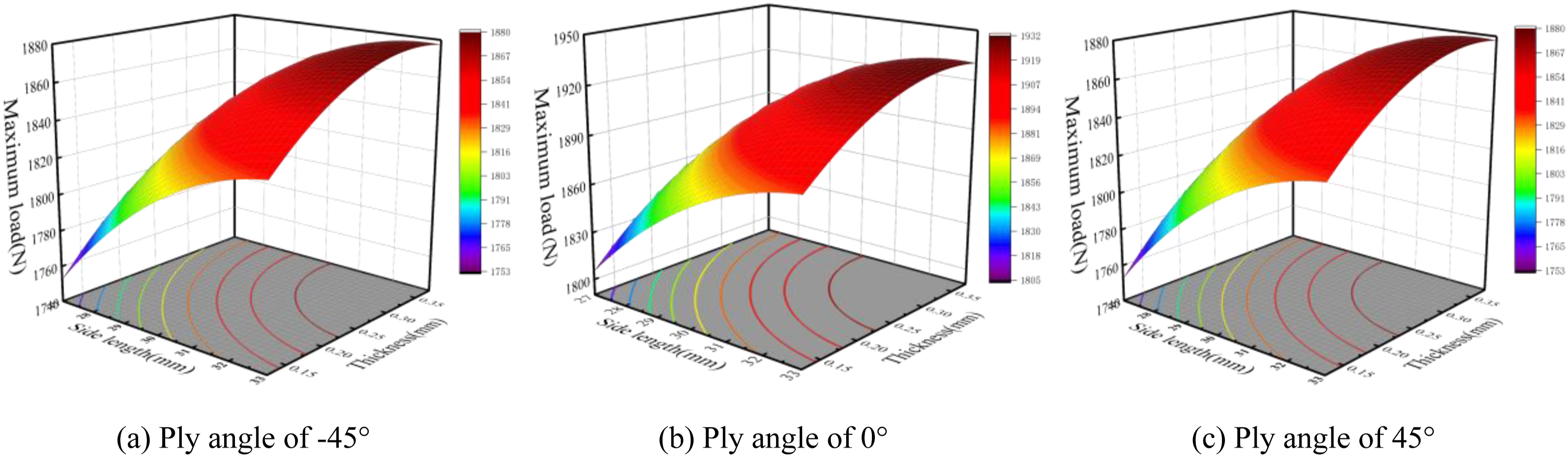
Preparation and bending test of perforation-damaged honeycomb sandwich structures before and after the scarf repair with and without optimized additional layers
Specimens preparation
Figure 7 shows the entire process of specimen preparation. The carbon fiber reinforced polymer panels with a thickness of 0.5 mm are prepared using T300/7901 unidirectional carbon/epoxy prepreg laid up in a [0/90]s sequence. The vacuum bag containing components is evacuated and checked for air leaks. The curing furnace is heated to 100°C at a rate of 1°C/min, then kept for 1 h, and heated to 120°C at a rate of 1°C/min for 90 min. In order to prefabricate damaged holes, a DL6392 sander and 400# sandpapers are used to polish the marked areas on the front and back surfaces of panels into a 3.819° slope. The core uses Nomex honeycomb core. The honeycomb sandwich structures are made by bonding the honeycomb core, panels, optimized additional layers, and patches with adhesive, and are pressed with heavy objects for 24 h. Specimen preparation process.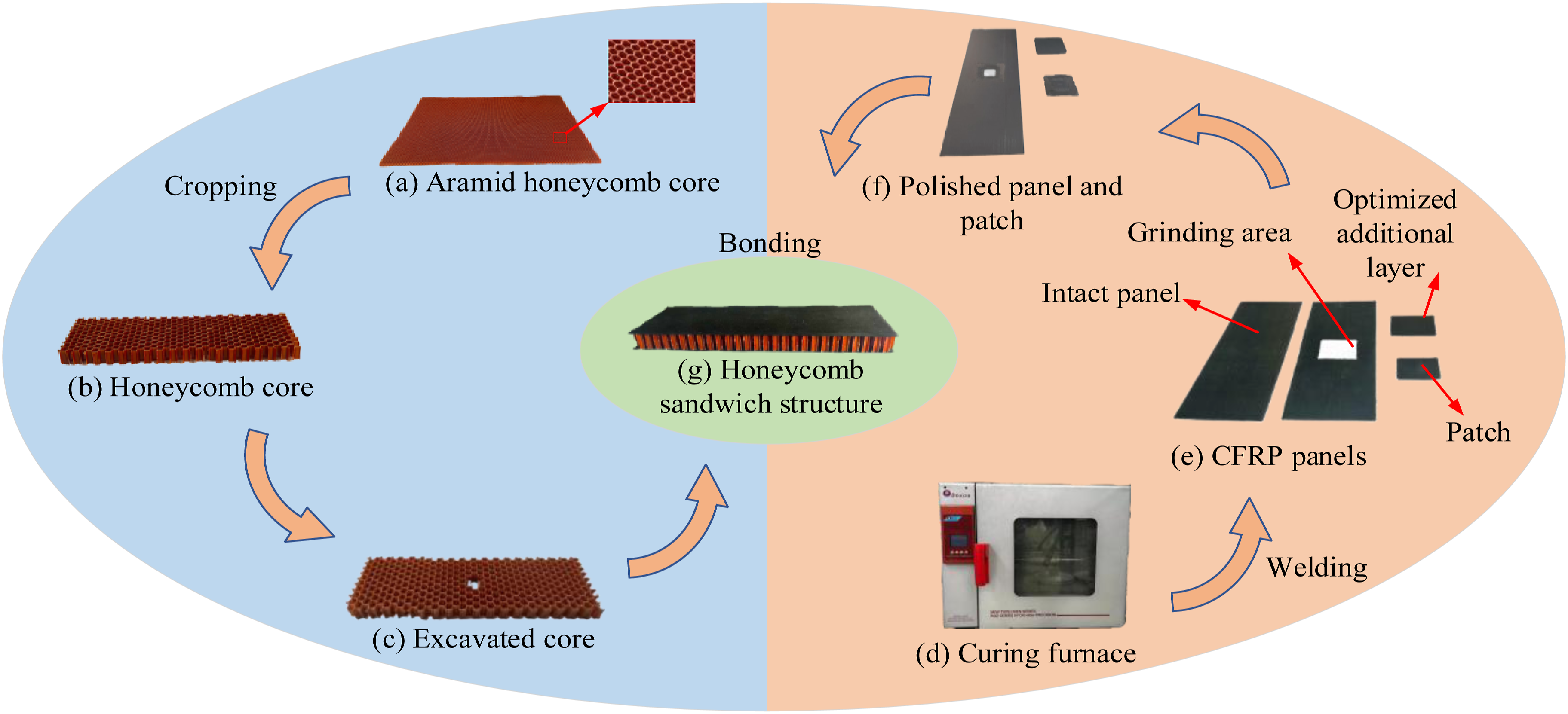
Three-point bending test platform
Figure 8(a) shows the experimental devices of three-point bending tests, which consists of high-definition cameras, two computers, and an AGS-X-50kND series precision electronic universal testing machine. Figure 8(b) shows the clamping and loading methods during the test. The specimen is symmetrically placed on two supports. Before the testing, the load and displacement need to be calibrated and zeroed. During the test, the displacement and load data are recorded by the displacement and load sensors, respectively, and the structural damage progression is captured by a high-definition camera under LED lamp illumination. The precision electronic universal testing machine is set with 100 sampling points, a loading rate of 2 mm/min, a load limit of 10 kN, and a sampling frequency of 50 Hz. Three-point bending test platform.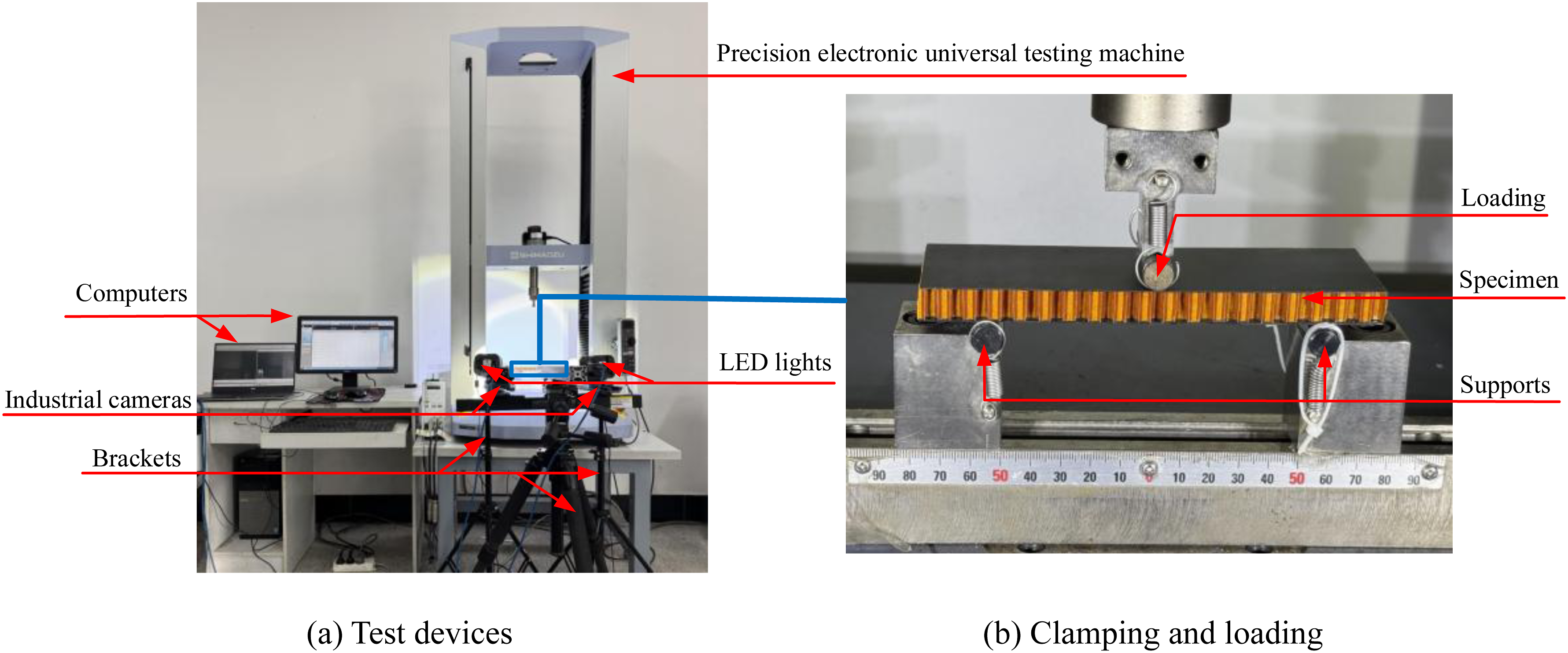
Experimental and numerical analysis of bending behaviors and damage evolution
Load-displacement curves, ultimate loads, and energy absorptions
The load-displacement curves, ultimate loads, and energy absorptions obtained from experiments and finite element simulations are analyzed, as shown in Figure 9. In Figure 9(a), the experimental and finite element curves show the same trends for the intact structure and the perforation-damaged structures after the scarf repair with and without optimized additional layers. Some errors exist between them, but within an acceptable range. Among them, based on the experimental curves, the failure displacements of honeycomb sandwich structures when adopting the scarf repair without additional layers and with optimized additional layers decrease by 0.5 mm and increase by 0.1 mm compared to the intact honeycomb sandwich structure, respectively. In Figure 9(b), the ultimate loads of structures when adopting the scarf repair without additional layers and with optimized additional layers decrease by 30% and 3.4% compared to the intact structure, respectively. The ultimate load of the structure when adopting the scarf repair with optimized additional layers increases by 38.5% compared to the structure when adopting the scarf repair without additional layers. In Figure 9(c), compared to the intact structure, the energy absorptions of structures when adopting the scarf repair without additional layers and with optimized additional layers decrease by 33.5% and increase by 17.6%, respectively. Compared to the structure when adopting the scarf repair without additional layers, the energy absorption of the structure when adopting the scarf repair with optimized additional layers increases by 76.7%. Taken together, the perforation-damaged structure after the scarf repair with optimized additional layers demonstrates significantly enhanced the bending performance, deformation ability, and energy absorption ability before failure. Experimental and numerical comparison of load-displacement curves as well as experimental ultimate loads and energy absorptions for the intact honeycomb sandwich structure and the perforation-damaged honeycomb sandwich structures after the scarf repair with and without optimized additional layers.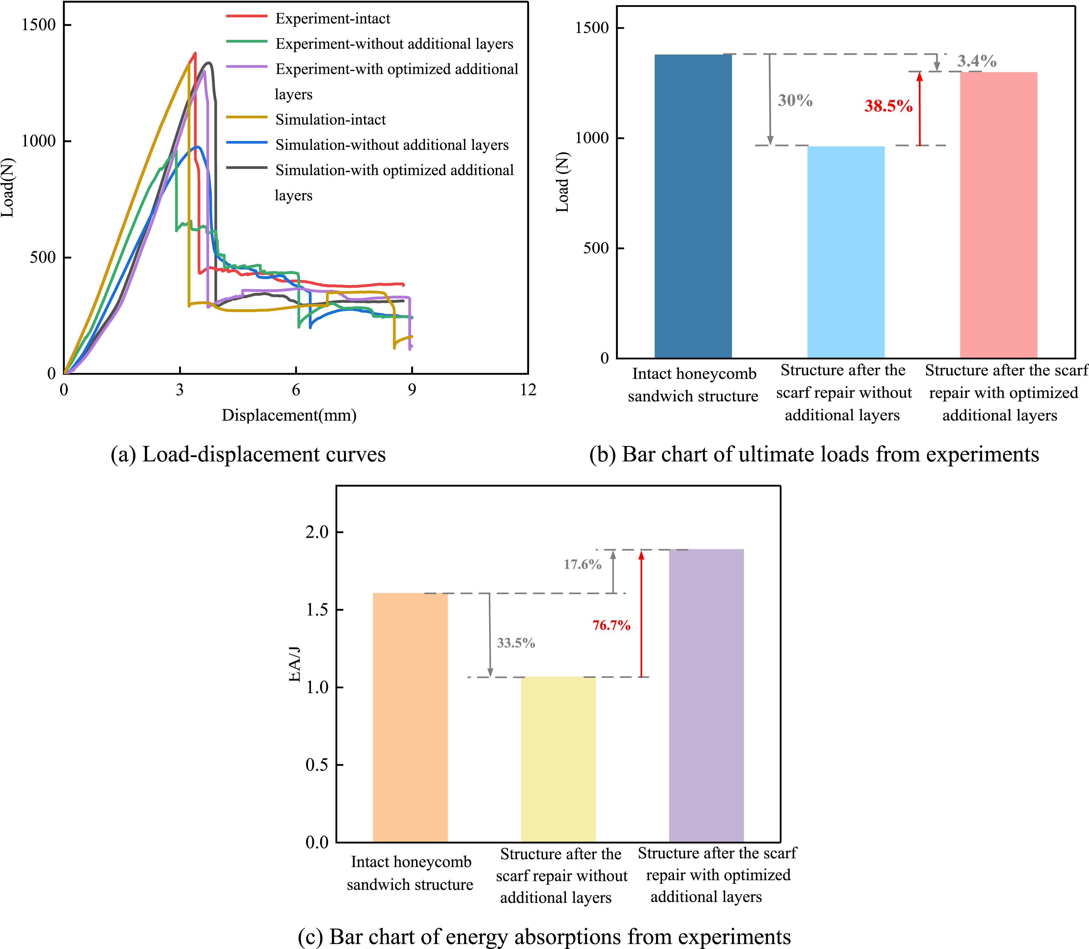
Damage evolution analysis based on experiment and simulation
Figures 10–12 give the experimental and numerical failure progressions in the intact honeycomb sandwich structure and the perforation-damaged honeycomb sandwich structures after the scarf repair with and without optimized additional layers. Overall, the damage evolutions from numerical simulation agree well with those from experimental observations for the intact structure and the scarf-repaired structures with and without optimized additional layers. In Figure 10(a), the intact honeycomb sandwich structure in experiment exhibits elastic deformation when the pressure head displacement is less than 3.4 mm, and reaches its peak load of 1378 N at a displacement of 3.4 mm. At this time, the brittle fracture occurs in the right core, accompanied by a sharp sound, and is identified as shear misalignment (marked by a red circle). And, the compression-induced depression appears in the core beneath the pressure head (marked by a red rhombus). As the displacement increases, the upper panel becomes concave, and the core on the right side beneath the pressure head is crushed and extends outward, accompanied by continuous fracture sounds, indicating the progressive development of shear failure (marked by a blue circle). Ultimately, the residual load is approximately 23% of the peak load. Experimental and numerical damage evolutions of the intact honeycomb sandwich structure. Experimental and numerical damage evolutions of the perforation-damaged honeycomb sandwich structure when adopting the scarf repair without additional layers. Experimental and numerical damage evolutions of the perforation-damaged honeycomb sandwich structure when adopting the scarf repair with optimized additional layers.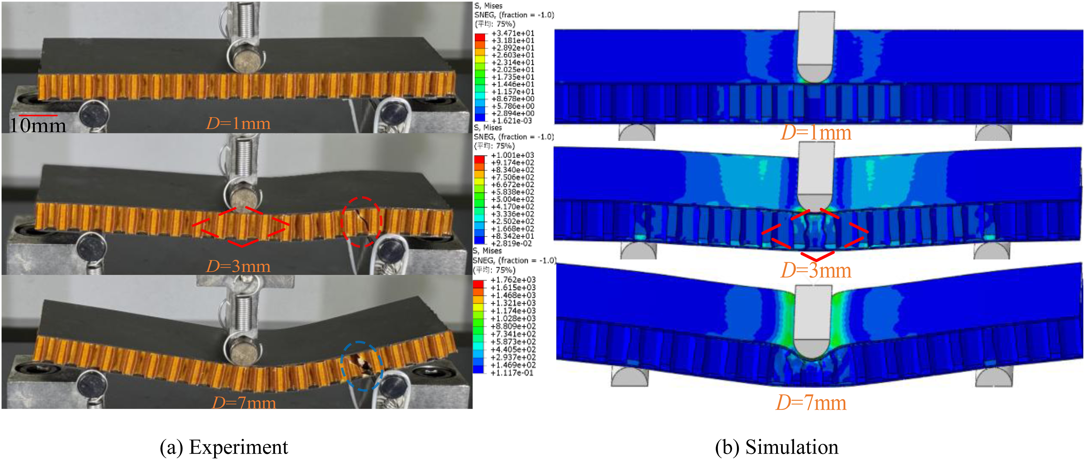
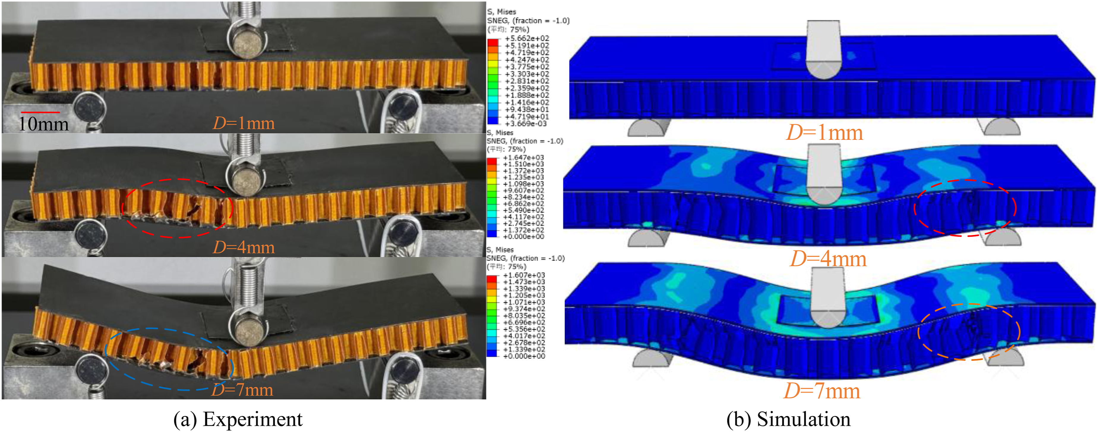
In Figure 10(b), the stress is at a relatively low level and mainly concentrated in the local area beneath the pressure head when the displacement is less than 3.2 mm, and reaches a peak load of 1337 N at a displacement of 3.2 mm. At this time, the severe stress concentration occurs, and the local buckling initiates in the core directly beneath the pressure head (marked by a red rhombus). As the displacement increases, the damage further progresses, accompanied by the core crushing beneath the pressure head and the significant bending deformation of the upper panel. Ultimately, the residual load is approximately 21% of the peak load.
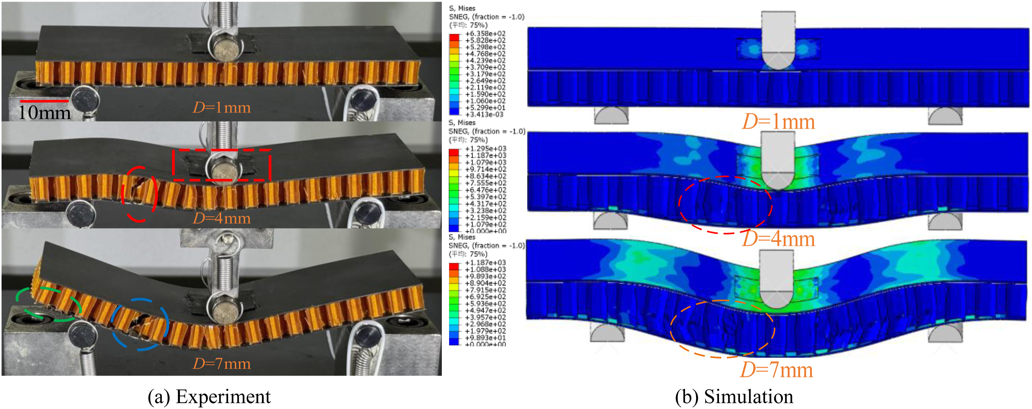
In Figure 11(a), the perforation-damaged honeycomb sandwich structure after the scarf repair without additional layers exhibits a damage evolution that is generally consistent with that of the intact structure in experiment. However, several distinct differences are observed. The peak load, that is, the load-bearing capacity, significantly decreases from 1378 N to 961 N, and the corresponding displacement reduces from 3.4 mm to 2.9 mm. This is because the insufficient bonding between the damaged structure and patches weakens the stiffness and load transfer capability of the sandwich structure. The failure initiates earlier and shifts in location, and the sandwich structure exhibits a shear failure on the left side of the core (marked by a red circle), accompanied by cracking and debonding in the upper panel patch (marked by a red box). This is because the scarf repair introduces the local stiffness discontinuity and stress concentration, resulting in a shift of the damage initiation location as well as the cracking and debonding in the upper panel patch. Continuous debonding between the lower panel and the core is observed (marked by a green circle) because the insufficient bonding in the lower repair area leads to premature interfacial failure.
In Figure 11(b), the perforation-damaged honeycomb sandwich structure after the scarf repair without additional layers exhibits the stress distribution and damage evolution that are generally consistent with those of the intact structure in simulation. However, several distinct differences are observed. The peak load decreases significantly from 1337 N to 968 N, and the corresponding displacement increases slightly from 3.2 mm to 3.3 mm. The minor increase in displacement is associated with the idealized defect-free interface and the progressive softening response in the cohesive zone model, and both them permit limited local deformation before final failure. The sandwich structure exhibits significant stress concentration and core shear buckling near the repair area (marked by a red dashed circle) due to the repair-induced stiffness discontinuity. The subsequent damage evolution shows a more significant outward propagation of shear failure in the core, accompanied by the significantly structural bending deformation (marked by an orange dashed circle). Ultimately, the residual load is approximately 28% of the peak load.
In Figure 12(a), the damage evolution of the perforation-damaged honeycomb sandwich structure after the scarf repair with optimized additional layers is generally consistent with that of the scarf-repaired structure without additional layers in experiment. However, several distinct differences are observed. The peak load of the structure with optimized additional layers increases to 1331 N at a displacement of 3.5 mm. This is because optimized additional layers enhance the structural stiffness and promote more effective load transfer across repair areas. The subsequent damage evolution becomes more stable and gradual. The core on the left side beneath the pressure head undergoes progressive extrusion, fragmentation, and outward extension (marked by a blue circle), accompanied by fragmentation sounds. This is because the enhanced interfacial bonding provided by optimized additional layers delays severe damage and suppresses debonding and cracking. Ultimately, the residual load is approximately 13% of the peak load.
In Figure 12(b), the stress distribution and damage evolution of the perforation-damaged honeycomb sandwich structure after the scarf repair with optimized additional layers are generally consistent with those of the scarf-repaired structure without additional layers in simulation. However, several distinct differences are observed. The peak load increases to 1358 N at a displacement of 3.7 mm. The damage location shifts from the left side to the right side because optimized additional layers alter the local stiffness distribution and stress transfer path. The stress concentration around repair areas is significantly lower than that of the scarf-repaired structure without additional layers. Ultimately, the residual load is about 21% of the peak load. Taken together, the optimized additional layers effectively alleviate local stress concentration and delay damage development.
Compression performance analysis of perforation-damaged honeycomb sandwich structures before and after the scarf repair with and without optimized additional layers
Finite element analysis
In order to investigate the impact of scarf repair with optimized additional layers on the compression performance of honeycomb sandwich structures with perforation damage, the finite element method is used for dynamic analysis. Among them, the modeling method, mesh division method, geometric parameters, and damage definition are all the same as those used in the bending model, as shown in Figure 13(a). Circular steel plate fixtures are added on both sides of the structure, and hard contact is established with the honeycomb sandwich structure, as well as the material property defined as a rigid material. The downward displacement load is applied at the top to simulate the uniaxial compression process, while a complete constraint is applied at the bottom to prevent positional deviation, as shown in Figure 13(b). Finite element model, mesh, loads, and restraints for compression analysis of perforation-damaged honeycomb sandwich structures after the scarf repair with optimized additional layers.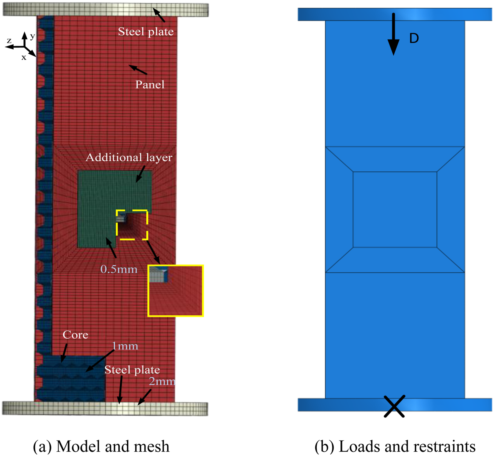
In order to investigate the compression performance improvement effect of adding optimized additional layers on scarf-repaired honeycomb sandwich structures with perforation damage, the load-displacement curves and ultimate loads of perforation-damaged honeycomb sandwich structures after the scarf repair with and without optimized additional layers are presented in Figure 14. In Figure 14(a), the displacement represents the pressure head motion rather than the pure axial deformation of structures. The initial non-linear stage is associated with the contacts between the pressure head, structures, and supports as well as the local contact at the beginning of loading. Hence, the initial low-slope stage in the numerical curves is retained and interpreted as a contact-induced response in the early loading stage. Before reaching the ultimate load, the three structures undergo elastic deformation, and the load-displacement curve shows a rapid increasing trend. After reaching the ultimate load, the curves all experience a rapid drop. Compared to the intact structure, the failure displacements of structures after the scarf repair without additional layers and with optimized additional layers decrease by 0.2 mm and 0.18 mm, respectively. In Figure 14(b), the ultimate loads of structures when adopting the scarf repair with and without optimized additional layers decrease by 2% and 34% compared to the intact structure, respectively, and the ultimate load of the structure when adopting the scarf repair with optimized additional layers increases by 49% compared to the structure when adopting the scarf repair without additional layers. Load-displacement curves and bar charts of ultimate loads for the intact honeycomb sandwich structure and the perforation-damaged honeycomb sandwich structures when adopting the scarf repair with and without optimized additional layers.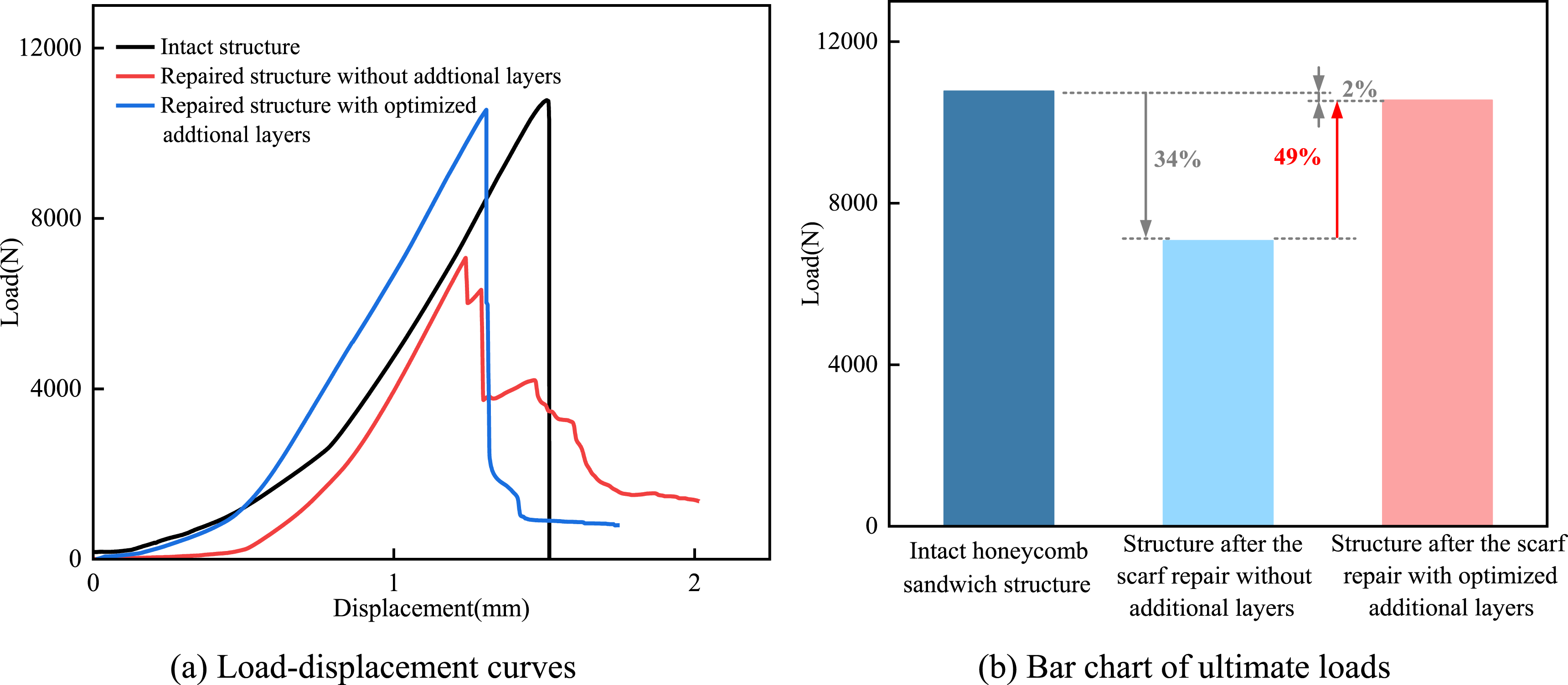
Compression test equipment and parameters
Compression performance testing is conducted on the intact honeycomb sandwich structure and the perforation-damaged honeycomb sandwich structures after the scarf repair with and without optimized additional layers. The compression testing devices primarily consist of a Z100 series precision electronic universal testing machine, high-definition camera, and two computers, as shown in Figure 15. The specimen is placed vertically at the center of the base. Before the testing, load and displacement calibration and zeroing are performed. During the test, displacement and load data are recorded by the displacement and load sensors, respectively, and the structural damage progression is captured by a high-definition camera under LED lamp illumination. The precision electronic universal testing machine is set with 100 sampling points, a loading rate of 2 mm/min, and a load limit of 10 kN. Compression test loads and clamps.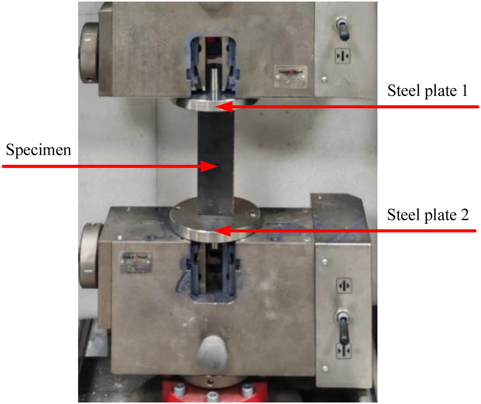
Experimental and numerical analysis of compression behaviors and damage evolution
Load-displacement curves, ultimate loads, and energy absorptions
The load-displacement curves and experimental results of ultimate loads and energy absorptions for the intact honeycomb sandwich structure and the perforation-damaged honeycomb sandwich structures after the scarf repair with and without optimized additional layers are shown in Figure 16. In Figure 16(a), the experimental and finite element curves show the same trends for the intact structure and the perforation-damaged structures after the scarf repair with and without optimized additional layers. Some errors exist between them, but within an acceptable range. The displacement in the experimental load-displacement curves represents the pressure head motion recorded by the testing machine rather than the pure axial deformation of specimens. The initial non-linear stage is attributed to the slack in the load train and support system. Since all specimens are tested under the same setup, the original curves are retained for comparative analysis. In addition, the experimental failure displacements of the perforation-damaged structure when adopting the scarf repair without additional layers and with optimized additional layers decrease by 0.25 mm and 0.2 mm compared to the intact structure, respectively. In Figure 16(b), the ultimate loads of the structures when adopting the scarf repair without additional layers and with optimized additional layers decrease by 26% and 9.5% compared to the intact structure, respectively. The ultimate load of the structure when adopting the scarf repair with optimized additional layers increases by 18.6% compared to the structure when adopting the scarf repair without additional layers. In Figure 16(c), compared to the intact structure, the energy absorptions of structures when adopting the scarf repair without additional layers and with optimized additional layers decrease by 43.3% and 15.6%, respectively. Compared to the structure when adopting the scarf repair without additional layers, the energy absorption of the structure when adopting the scarf repair with optimized additional layers increases by 48.8%. In summary, the compression performance, deformation ability, and energy absorption ability before failure of perforation-damaged structures after the scarf repair with optimized additional layers have been significantly improved. Experimental and numerical comparison of load-displacement curves as well as experimental ultimate loads and energy absorptions for the intact honeycomb sandwich structure and the perforation-damaged honeycomb sandwich structures after the scarf repair with and without optimized additional layers.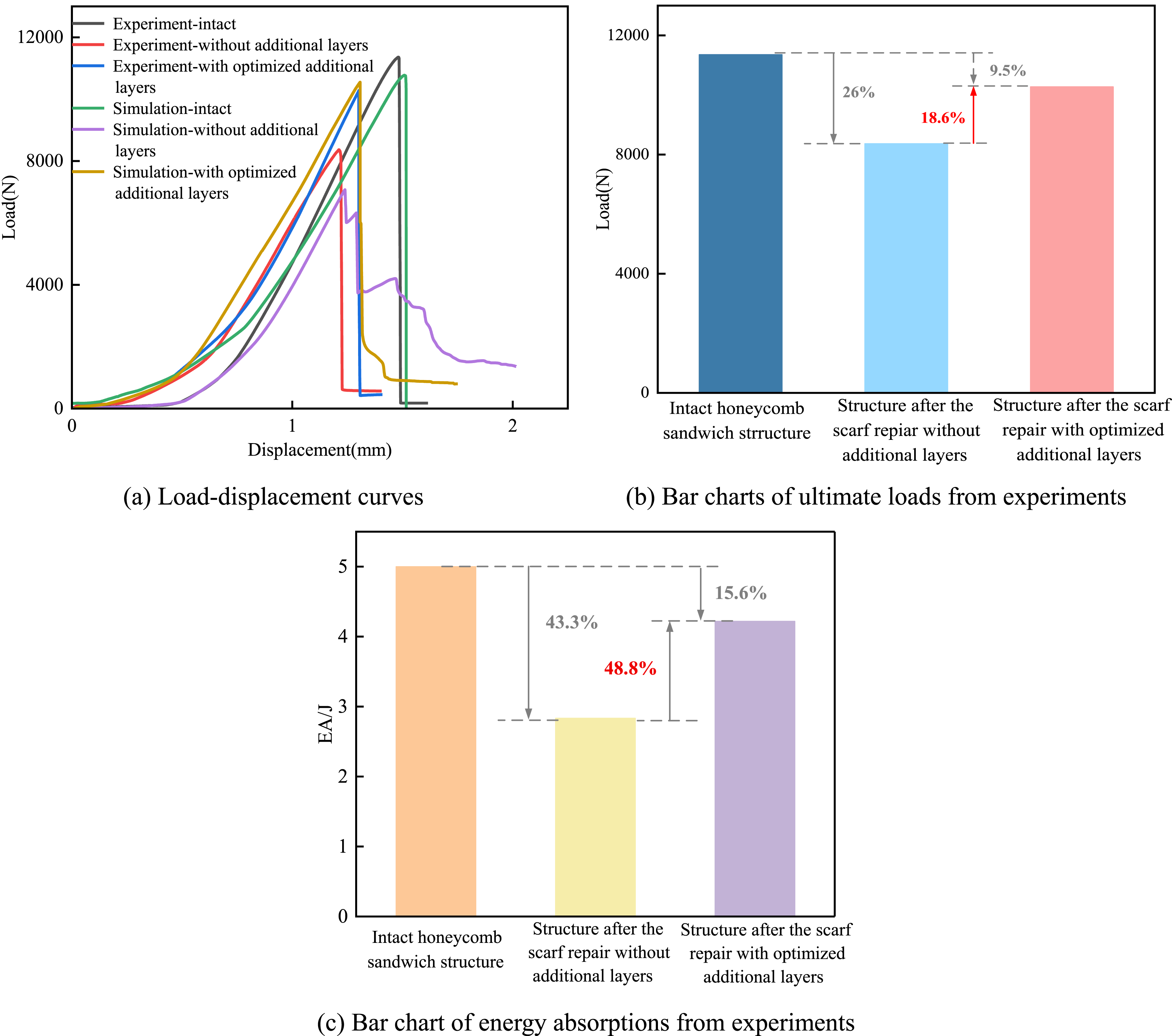
Damage evolution analysis based on experiment and simulation
The internal behaviors of composite laminates are difficult to be observed directly in experiment, and the buckling and interfacial damage cannot be clearly identified from a frontal view. To reveal hidden phenomena, the stress distributions are presented in Figure 17 for the intact honeycomb sandwich structure and the scarf-repaired honeycomb sandwich structures with and without optimized additional layers. For the intact structure, the stress is mainly concentrated in the top half, and the continuous wrinkling further intensifies the stress, eventually leading to the loss of load-bearing capacity. For the scarf-repaired structure without additional layers, severe stress concentration occurs around patches, and the maximum equivalent stress reaches 1850 MPa. This is because the dominant load transfer along the 0° fiber direction of composite laminates induces significant anisotropy in repair areas. Hence, premature debonding occurs in experiment and simulation, leading to the structural instability and the loss of load-bearing capacity. For the scarf-repaired structure with optimized additional layers, severe debonding is effectively suppressed. The maximum equivalent stress in repair areas reduces to 667 MPa, i.e., a 63.95% decrease, and the debonding and cracking in repair areas disappear. This is because the optimized additional layers alter the load transfer. The stress is mainly concentrated in the top half, which is similar to the intact structure. Experimental failure modes and numerical stress distributions for the intact honeycomb sandwich structure and the perforation-damaged honeycomb sandwich structures after the scarf repair with and without optimized additional layers.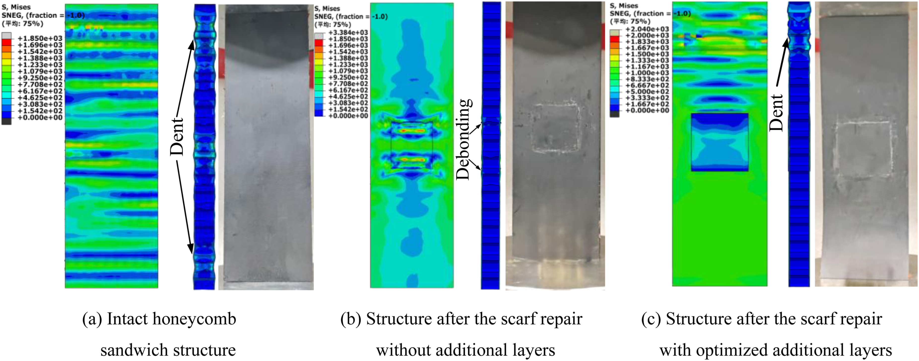
Microscopic damage mechanisms analysis based on damage variable contours
The damage variable distributions of the intact honeycomb sandwich structure and the perforation-damaged honeycomb sandwich structures after scarf repair with and without optimized additional layers are presented in Figure 18 to further analyze the microscopic damage mechanisms. In Figure 18, (I) and (II) denote the matrix and fiber compression damage contours, respectively. The damage variables are limited to 0.83 for fiber and 0.9 for matrix to maintain the residual stiffness and numerical stability. For the intact structure, the matrix and fiber compression damage are mainly concentrated at upper and lower loading edges. The damage at the load-applied side is more severe and develops into severe matrix fractures and fiber fractures, resulting in the loss of load-bearing capacity. For the scarf-repaired structure without additional layers, severe damage occurs around patches. The geometric discontinuity causes massive matrix fractures and local fiber fractures in repair areas, resulting in the overall structural instability and load-bearing capacity decrease. For the scarf-repaired structure with optimized additional layers, the significant damage is shifted away from patches and mainly concentrated on the load-applied side, which is similar to the damage distribution of the intact structure. The severe matrix and fiber fractures occur on the load-applied side. In summary, the optimized additional layers effectively alleviate the damage around patches and suppress the interfacial delamination. Damage evolutions for the intact honeycomb sandwich structure and the perforation-damaged honeycomb sandwich structures after the scarf repair with and without optimized additional layers.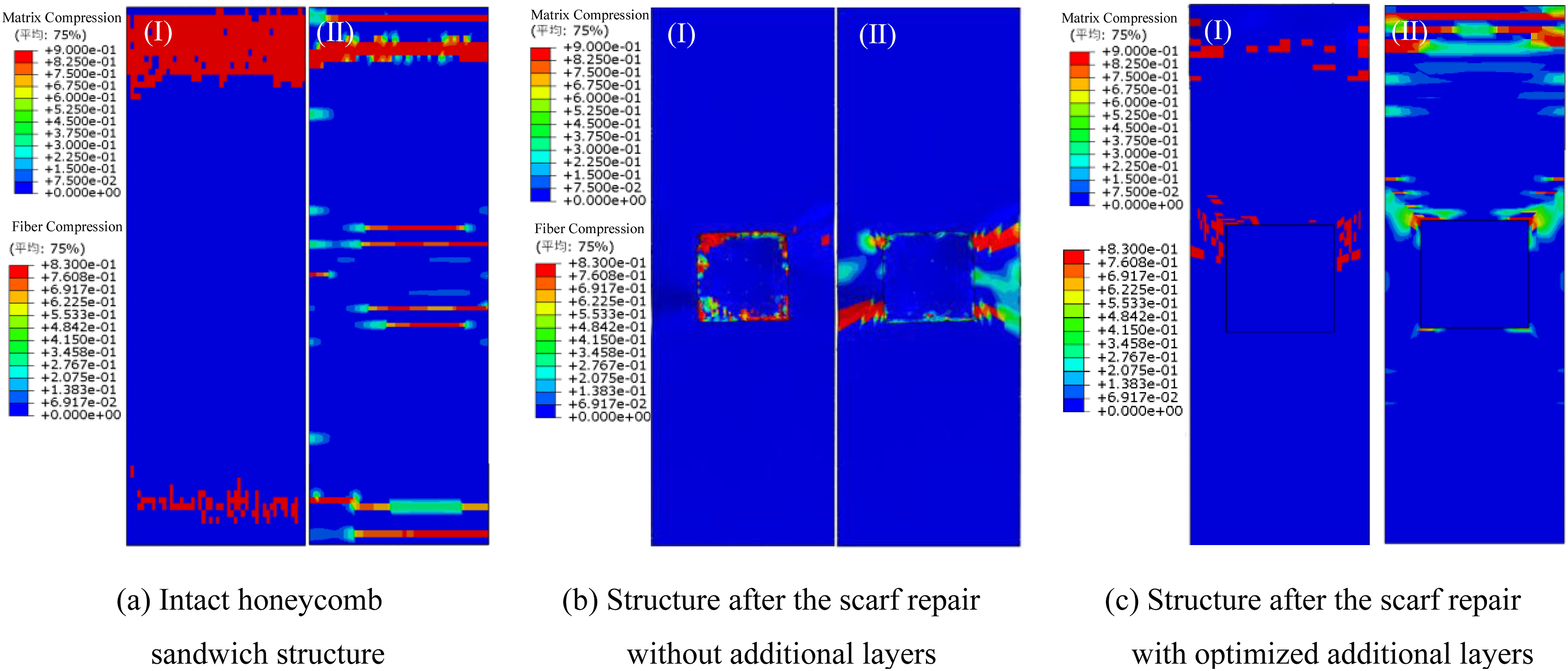
Conclusions
A comprehensive study on the enhancement effect of the scarf repair with optimized additional layers is conducted for the bending and compression properties of the carbon fiber composite-aramid paper honeycomb sandwich structure with perforation damage. The main conclusions are as follows: (1) The optimal parameters of additional layers are determined to be 30 mm in the side length, 0.25 mm in the thickness, and 0° in the ply angle. This is because the maximum load shows nonlinear relationships with the design parameters of optimized additional layers. Specifically, as the side length and thickness increase, the maximum load rises rapidly at first, and this upward trend gradually slows down. As the ply angle increases, the maximum load improves first and then declines. (2) When the optimized additional layers are adopted during the scarf repair of perforation-damaged honeycomb sandwich structure, the experimental load-bearing and deformation abilities increase by 38.5% and 20.6% for bending as well as 18.6% and 24% for compression, and the experimental energy absorption before failure increases by 76.7% for bending and by 48.8% for compression, respectively. This is because the scarf repair with optimized additional layers effectively alleviates the stress concentration and reduces the maximum equivalent stress in repair areas by 63.95%. (3) When adopting the scarf repair without additional layers, the core experiences shear failure during bending tests, and continuous debonding also occurs between the panel and core. And, the compression fracture and debonding occur around the patch during compression tests. When adopting the scarf repair with optimized additional layers, during bending tests, the core exhibits compression deformation, followed by brittle fracture, while the panels show no obvious damage. And during compression tests, the panels first experience local buckling, followed by denting that causes the core to collapse, eventually leading to fracture in the dented area of panels.
Footnotes
Funding
The authors disclosed receipt of the following financial support for the research, authorship, and/or publication of this article: This work was supported by the Natural Science Foundation of Tianjin (Grant No. 23JCZDJC00460) and the National Natural Science Foundation of China (Grant No. 51805369).
Declaration of conflicting interests
The authors declared no potential conflicts of interest with respect to the research, authorship, and/or publication of this article.
Data Availability Statement
Some or all data, models, or code that support the findings of this study are available from the corresponding author upon reasonable request.