
Abstract
A theoretical model for predicting kink-band formation in unidirectional composites is developed. In contrast to previous models, the proposed model takes into account the shear deformation in the non-misaligned regions when determining the fiber misalignment angle, and introduces an analytical approach for determining the orientation of the kink-band plane based on the applied stress state, instead of the conventional approach based on maximizing a failure index. Based on this model, a three-dimensional failure criterion for composites is further developed, which considers the effect of fiber misalignment under all stress states and therefore overcomes the discontinuity in the failure envelope produced by Pinho’s criterion. Using the proposed model and criterion, the failure behavior of unidirectional composites under various stress states is analyzed. A notable finding is that, under the
Highlights
• A theoretical model is proposed to predict the formation of kink bands. • The model incorporates the effects of all stress components on kink-band formation. • A three-dimensional failure criterion accounting for fiber misalignment is developed. • The influence of fiber misalignment is considered under any stress states.
Introduction
The failure mechanism of composite materials has always been a focal topic of interest among researchers. Compared to other failure modes, the failure mechanism of fiber kinking is more complex. Experimental results indicate that localized kink bands are observed for unidirectional (UD) fiber-reinforced composites after high longitudinal compressive failure.1–3 For the mechanism of kink-band formation, some researchers follow Rosen’s hypothesis. Rosen 4 modeled the fibers as initially straight, linearly elastic plates embedded in a linearly elastic matrix, and analyzed elastic micro-buckling under the assumption of perfectly aligned fibers. The shear mode of microbuckling proposed by Rosen depends on the matrix shear modulus and is independent of any initial imperfection. In contrast, Argon 5 assumed the existence of an initial fiber misalignment, which generates a shear stress between fibers under axial compression. This shear stress further rotates the fibers and amplifies itself, leading to a local shear instability and the formation of a kink band. The critical compressive stress predicted by Argon’s model depends on the matrix shear yield stress and the initial misalignment angle, rather than on the elastic shear modulus. Some subsequent studies have shown that Argon’s hypothesis seems more reasonable. For instance, based on the experimental observations, Schultheisz and Waas 6 pointed out that the formation of kink bands seems to be triggered by local microstructural defects, such as fiber misalignments and matrix cracking. Furthermore, Sun et al. 7 used X-ray computed tomography (CT) to observe the formation of kink bands and concluded that the presence of micro-voids leads to stress concentrations in the matrix and reduces the lateral support of the fibers, eventually leading to kinking failure. These experiments support Argon’s hypothesis.
Numerous studies have indicated that the initial fiber misalignment in composites primarily originates from manufacturing-induced imperfections.7,8 Localized fiber misalignment results in shear stresses in the matrix under longitudinal compression. The shear stresses induce additional fiber rotation, which in turn leads to a further increase in the shear stresses. This closed-loop effect will ultimately lead to failure. At present, extensive research has been conducted on the magnitude and distribution characteristics of initial fiber misalignment.9–11 Recently, Zheng et al. 8 performed a statistical analysis of fiber orientations in unidirectional composites using CT, revealing that the misalignment angles approximately follow a normal distribution and exhibit similar magnitudes across different directions. Varandas et al. 12 developed a micromechanical model that treats fiber misalignment as a stochastic process to investigate its influence on compressive failure behavior. Their results showed that, although individual fibers exhibit different initial misalignment directions, after peak load, the fibers within the kink bands tend to align in a consistent orientation.
Extensive research has been conducted on fiber kinking failure in composites. Gu et al. 13 performed longitudinal compression tests on carbon fiber-reinforced composites under different strain rates, and analyzed the failure morphology using scanning electron microscopy (SEM). The results showed that under dynamic loading, failure was dominated by kink bands and longitudinal splitting, whereas under quasi-static loading, fiber kinking was the primary failure mode. Takahashi et al. 14 carried out uniaxial compression tests on carbon fiber reinforced plastics (CFRP) and employed CT to investigate the stress-strain response and failure process. They reported that the local fiber bending deformation occurred before the peak load. Clay et al. 15 used CT to observe the evolution of kink bands in notched composite specimens under longitudinal compression, and found that kink bands primarily formed in the central 0° ply region.
The aforementioned studies primarily investigated the effect of fiber misalignment on the longitudinal compressive failure of composites through experimental approaches. In this context, incorporating fiber kinking into failure criteria has emerged as an important focus of recent research. Although numerous failure criteria for composites have been proposed historically, 16 and new ones continue to emerge in recent years,17–20 most of them do not account for fiber kinking. Consequently, their ability to predict this specific failure mode remains limited. This highlights the necessity of incorporating fiber kinking into failure criteria. In existing failure criteria that account for fiber kinking, the initial fiber misalignment angle is typically treated as a fixed value, rather than a randomly distributed variable as observed in real structures. Dávila and his workers21,22 proposed a method to solve the fiber misalignment angle for a generic stress state. Pinho et al. 23 argued that the initial misalignment angle is a material property that can represent initial defects, and proposed a three-dimensional (3D) failure model. In addition, many macroscopic failure criteria considering fiber misalignment have been proposed in Refs. 24–26. Meanwhile, a number of studies have focused on developing numerical models that incorporate the fiber kinking failure.27–30 For instance, Davidson and Waas 27 distinguished the mesoscale and microscale misalignment of fibers in the micromechanical model and studied the effect of fiber misalignment on failure under longitudinal compression. Ding et al. 28 introduced a three-dimensional elasto-plastic damage model that accounts for fiber kinking failure. Divse et al. 29 proposed a progressive damage model incorporating fiber kinking behavior. Xue and Kirane 31 developed a microplane model to simulate the initiation and propagation of kink bands under longitudinal compression. In addition, the finite element analyses on the influence of fiber misalignment have been carried out in Refs. 32–36.
Although various failure criteria incorporating fiber misalignment have been developed, they share a common theoretical basis. Following the framework originally established by Argon. 5 Dávila and his co-workers21,22 developed the first widely adopted analytical failure criterion that incorporates this mechanism. Most subsequent criteria, including those of Pinho et al. 23 and Refs. 24–26, have been developed on the basis of this work. Although these criteria differ in the choice of the matrix failure function, they adopt similar approaches in handling fiber misalignment and determining the orientation of the kink-band plane. As a result, the previous failure criteria considering fiber kinking share several notable limitations. Specifically, they neglect the influence of shear deformation in the non-misaligned regions on the fiber misalignment angle and incorrectly determine the angle of the kink-band plane using failure indices; in addition, they consider the effect of fiber misalignment only when σ11 < 0, leading to discontinuities in the predicted failure envelopes. To overcome these limitations, this study develops a theoretical model for kink-band formation, based on which a three-dimensional failure criterion is proposed. Through theoretical analysis and experimental validation, the effectiveness of the proposed model and criterion is demonstrated.
The theoretical model for kink-band formation
Following previous studies,21–24 the present study assumes that the initial fiber misalignment angle θ
i
is a fixed value rather than a randomly distributed variable. In real composites, in addition to fiber misalignment, various manufacturing-induced imperfections such as fiber waviness, voids, and matrix defects also influence the failure behavior. Therefore, θ
i
is treated here as an effective parameter representing the combined effect of these imperfections, and is calibrated from the experimentally measured longitudinal compressive strength
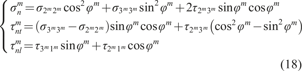
Figure 1 shows a 3D model with a kink-band plane for UD composites. The coordinate system 123 is aligned with the composite material axes, where the 1 axis is parallel to the fiber direction and the 2 and 3 axes represent the transverse directions. The coordinate system 3D model with a kink-band plane. (a) The 3D model; (b) the rotational components in the kink-band plane.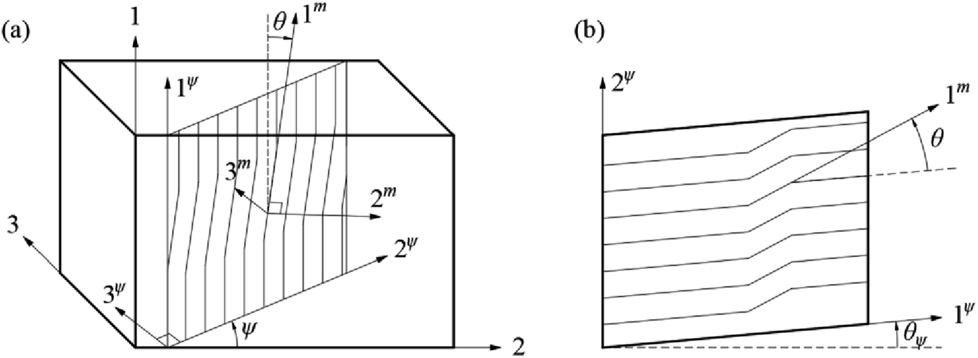
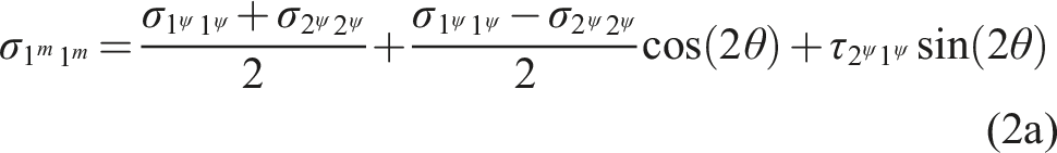
For a given stress state (


The stress state in the frame


Fiber misalignment angle
Previous studies21–25 argued that the fiber misalignment angle for generic loading conditions is given by

However, the rotational component in non-misaligned regions is neglected in equation (3). In fact, under generic loading conditions, there are rotational components in both misaligned and non-misaligned regions. Therefore, the present study defines the effective rotational component,


For a given composite,

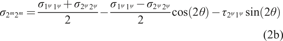
Hahn and Tsai
38
proposed a polynomial to describe the nonlinear shear response of materials:
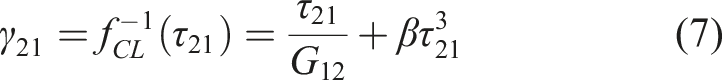
Although equation (7) accounts for shear nonlinearity, it does not consider the effect of the transverse stress σ22 on the shear deformation. Experimental studies by Puck and Schürmann39,40 show that transverse stress σ22 significantly influences the longitudinal shear nonlinear behavior of Glass/Epoxy composites. However, due to the lack of corresponding experimental data for other material systems, it remains challenging to establish a generalized shear stress-strain constitutive law that incorporates the effect of σ22. Therefore, in the present study, equation (7) is still employed as the nonlinear constitutive law for the materials.
Following the shear constitutive law given by equation (7) and using the small angle approximation, equation (5) can be expressed as
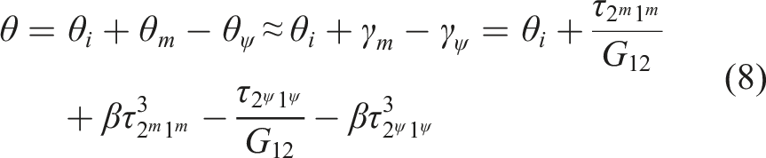
In equation (8), the approximation is based on the small-angle assumption. Since the fiber misalignment angle and the corresponding shear strain in composites are both small, the resulting error can be neglected. This approximation is consistent with previous studies.21–25
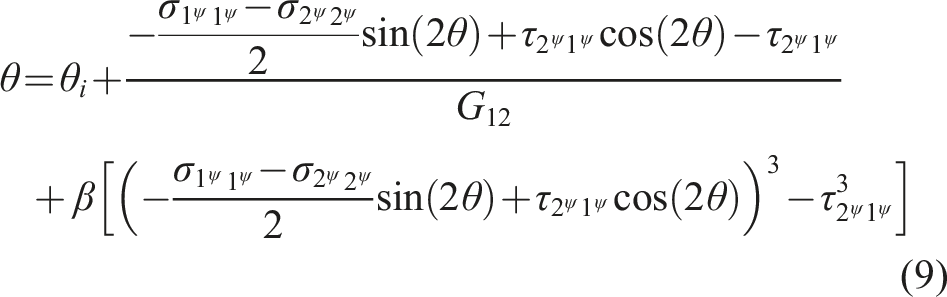
Substituting equation (2d) into equation (8) gives
Angle of the kink-band plane
Pinho et al.
23
suggested that in the kink band, the fibers rotate consistently in the same direction forming kink-band plane, and the angle of the kink-band plane,
This method for determining
For the E-glass/MY750 composite from Ref. 41, under the combined longitudinal and transverse compressive stresses with a stress ratio of
The reason for the contradiction is that the angle of the kink-band plane should not be calculated by the kinking failure index. Sun et al. 7 studied the kinking failure of UD composites under longitudinal compression. In order to understand the mechanism of kink-band formation, they interrupted the compressive loading before the failure of the specimen and found kink bands could be observed in the test specimens clearly. This implies that under external loads, the formation of the kink bands and the increase in the fiber misalignment angle in UD composites represent internal deformations of the materials, which are independent of whether the materials fail. In other words, before the material fails, the kink bands may have formed. Therefore, it is unreasonable to use the kinking failure index to calculate the angle of the kink-band plane.
Based on the above analysis, the present study argues under the external loads, the localized misaligned fibers will tend to rotate toward the direction where the fiber misalignment angle is maximum. Finally, the kink bands form in the plane with the largest fiber misalignment angle.
The fiber misalignment angle can be regarded as a function of the stress state, the initial misalignment angle, and the angle of the kink-band plane:

For a given stress state and initial misalignment angle θi, the angle of kink-band plane, ψ, is incrementally varied over the range 0° ≤ ψ < 180° with a step size of 1°. For each ψ, a candidate fiber misalignment angle is computed; the maximum value over all sampled ψ is taken as the final fiber misalignment angle θ, as defined by equation (11). The corresponding ψ identifies the angle of the kink-band plane.
At this point, the theoretical model for kink-band formation has been established. For a given composite material under external loading, the fiber misalignment angle,
Development of three-dimensional failure criterion
Failure modes in non-misaligned regions
Fiber tensile failure in non-misaligned regions
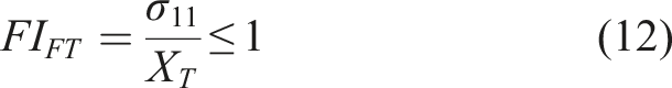
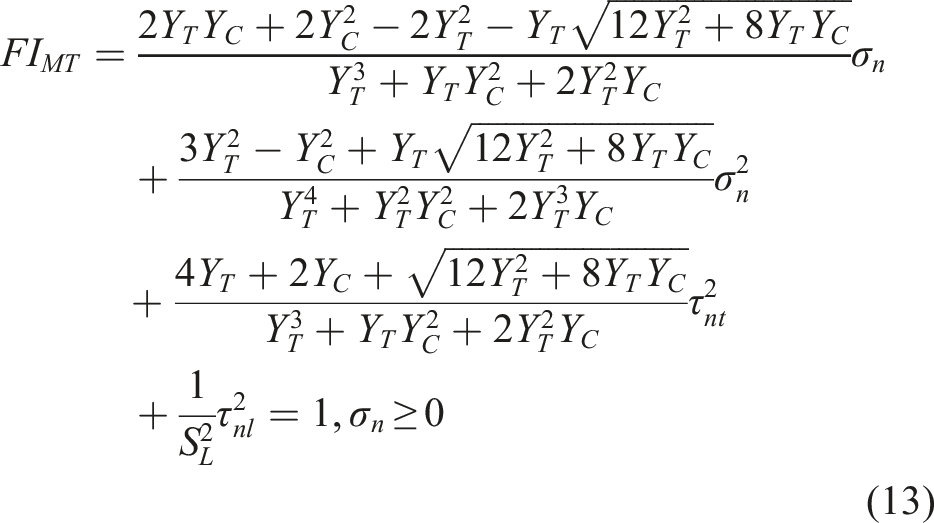
The present study adopts the maximum stress criterion to predict fiber tensile failure, and the failure index (FI) for fiber tensile failure in non-misaligned regions is given by
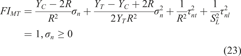
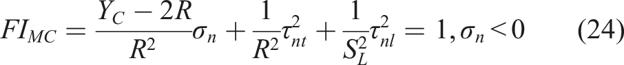
Matrix tensile/compressive failure in non-misaligned regions
The matrix failure criteria of UD composites have been studied extensively.21–23,40,42,43 Among them, Puck’s matrix failure criterion is widely used in engineering. However, it contains a large number of empirical parameters, which limits its further development. To address this limitation, a matrix failure criterion independent of empirical parameters has recently been proposed for brittle composites characterized by
Failure modes in localized misaligned regions
Experimental observations7,45 have shown that failure in materials under high longitudinal compressive stress is caused by fiber kinking in localized misaligned regions. Based on this, Pinho et al.
23
proposed that the failure in localized misaligned regions should be considered when σ11 < 0. However, their approach neglects the effect of fiber misalignment under other stress states. This limitation results in a discontinuous failure envelope when positive and negative initial fiber misalignment angles (± Failure envelope of 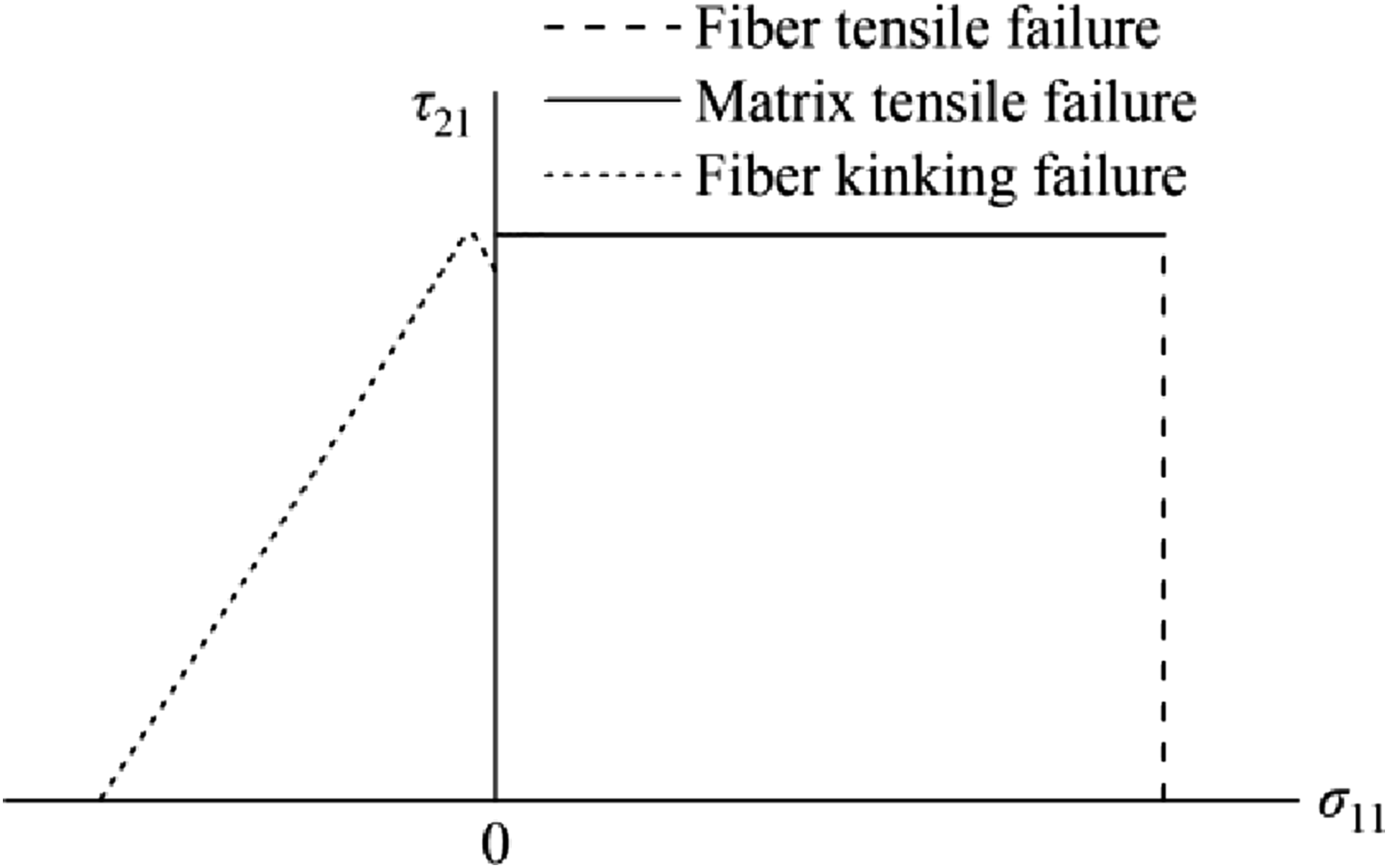
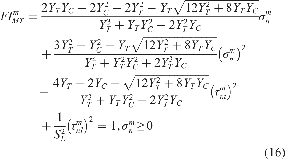
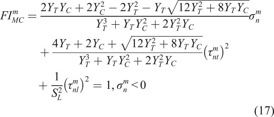
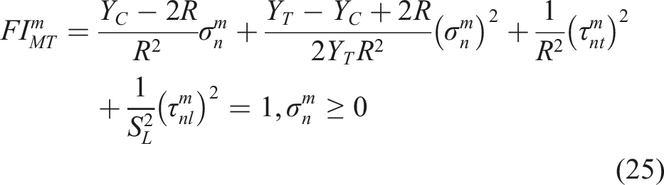
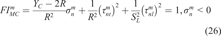
Matrix tensile/compressive failure in localized misaligned regions
The failure indices for matrix tensile and compressive failure in localized misaligned regions are consistent with the forms of equations (13) and (14), respectively:
Elastic instability of the matrix in localized misaligned regions
According to the studies of Pinho et al.,
46
another failure mode in localized misaligned regions is the elastic instability of the fibers in the localized misaligned regions, which occurs only in the presence of longitudinal compressive stress. To characterize this failure mode, the following expressions are obtained from equations (2d) and (7):
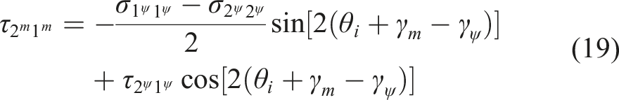
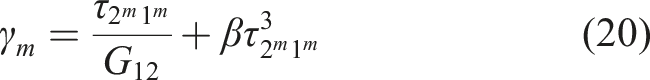
Equation (19) is the shear stress in the localized misaligned region induced by longitudinal compressive stress, and equation (20) is the shear stress–strain constitutive law. The elastic instability mode is characterized by the relationship between these two curves, and the corresponding failure condition is determined from the following analysis. As shown in Figure 3(a), the curve given by equation (19) represents the shear stress in localized misaligned regions induced by longitudinal compressive stress of 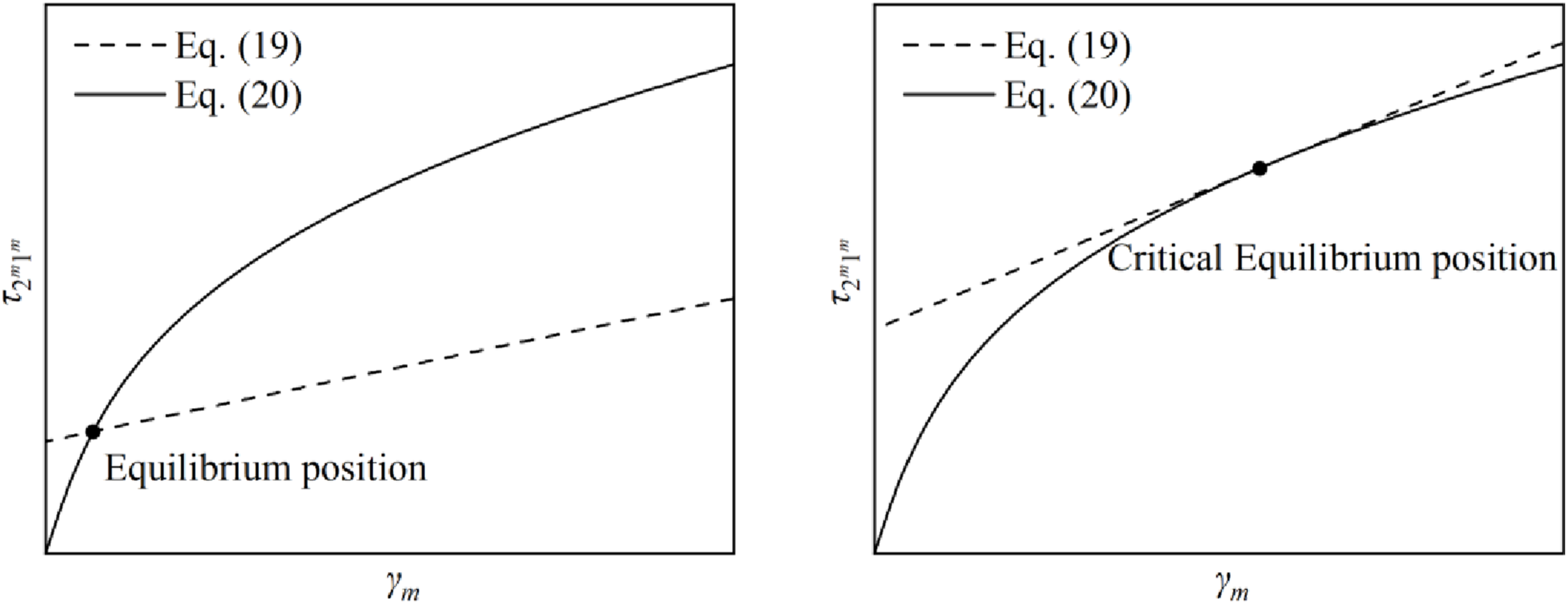
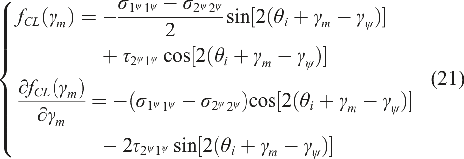
When elastic instability occurs, the curve of equation (19) intersects the curve of equation (20) and they have the same slope at the intersection point. Hence, the failure stresses corresponding to the elastic instability can be solved by
Correction of basic strengths
The strength is defined as a single stress that can cause failure in the absence of other stresses. The proposed failure criteria contain four strengths, i.e.,
For ease of subsequent derivation, the parameter R is defined as.
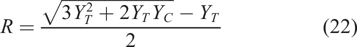
The parameter R is determined by the transverse tensile and compressive strengths. For brittle composites where
Equations (13), (14), (16) and (17) can be rewritten as
The transverse tensile strength
Under uniaxial transverse tension, the failure of the matrix may occur in both the localized misaligned regions and the non-misaligned regions. The failure region can be determined by comparing the magnitude of the failure indices.
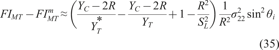
For non-misaligned regions, under uniaxial transverse tensile stress
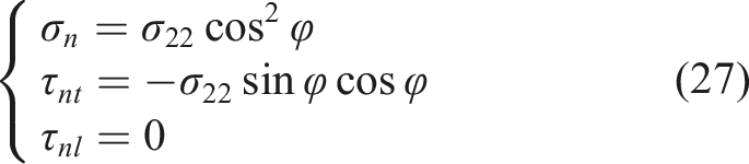
In the stress state given by equation (27), the matrix tensile failure index of non-misaligned regions,
For localized misaligned regions, under uniaxial transverse tensile stress
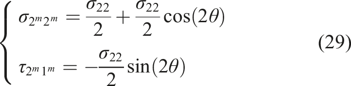
Under the combination of transverse tensile stress
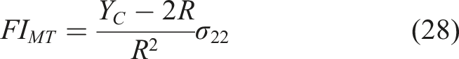
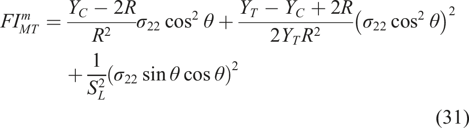
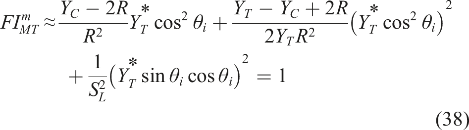
The matrix tensile failure index of localized misaligned regions,
The failure region can be determined by comparing equations (28) and (31):
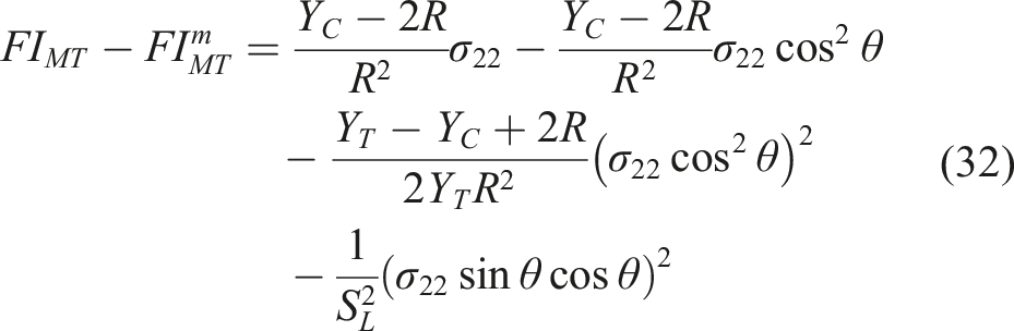
Equation (32) can be rewritten as
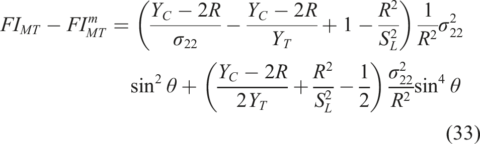
The initial misalignment angle of the material generally does not exceed a few degrees. Under transverse tensile stress of
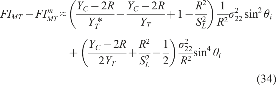
Since
For a large number of composites in Refs. 41,47,48, the values of parameter R, solved by using equation (22), are all lower than the longitudinal shear strength, i.e.,

Equation (36) means that for composites where
It is assumed that the matrix in the non-misaligned regions fails first under uniaxial transverse tension and

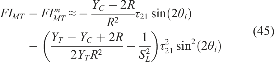
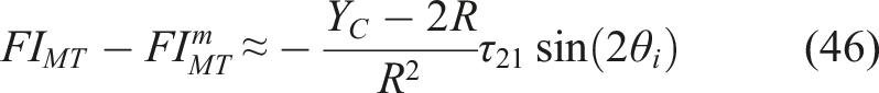
Equation (37) means that the matrix in the localized misaligned regions fails first under uniaxial transverse tension, which contradicts the initial assumption. Hence, the matrix in the localized misaligned regions must be the first to fail under uniaxial transverse tension, i.e.,
The true transverse tensile strength,
The transverse compressive strength
Under uniaxial transverse compressive stress, the angle of the kink-band plane by solving equation (11) is 90°. Hence, the stress state of the local misaligned regions and the non-misaligned regions is identical, and
The longitudinal shear strength
Under pure longitudinal shear stress
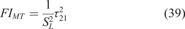
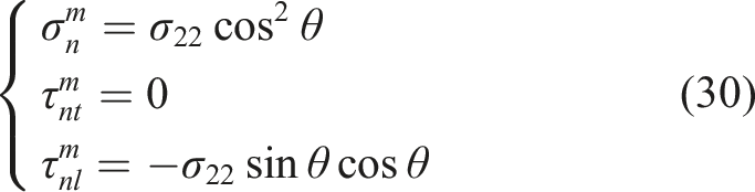
For localized misaligned regions, under pure longitudinal shear stress, the angle of the kink-band plane is 180° by solving equation (11). The stress state in localized misaligned regions is given by
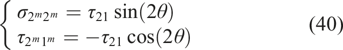
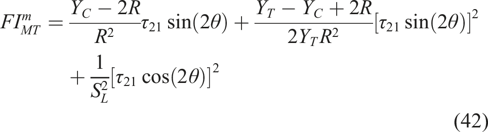
Under the combination of transverse tensile stress
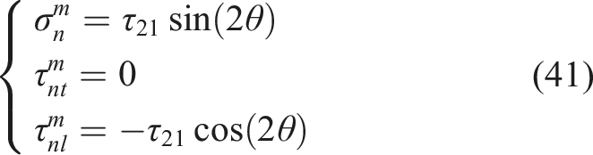
Substituting equation (41) into equation (25) to obtain the matrix tensile failure index of localized misaligned regions:
The failure region can be determined by comparing equations (39) and (42):
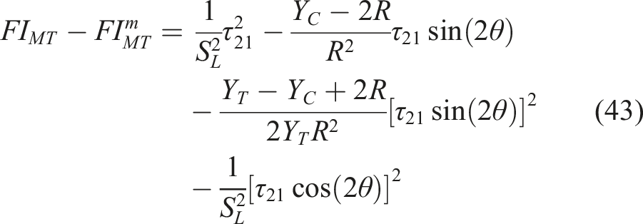
Equation (43) can be rewritten as
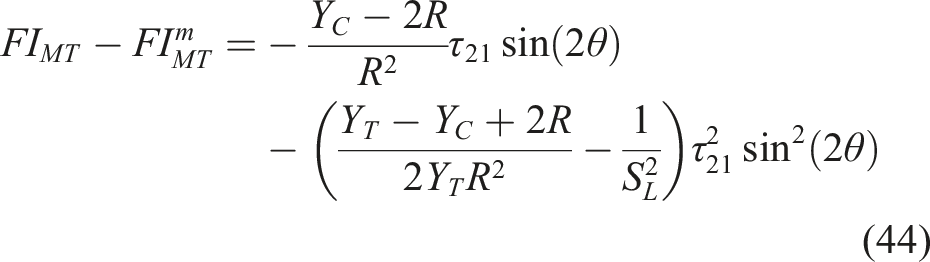
Under pure longitudinal shear stress, the fiber misalignment angle hardly changes, i.e.,
Since
Since

Equation (47) means that the matrix in localized misaligned regions fails first under pure longitudinal shear stress, and thus
When
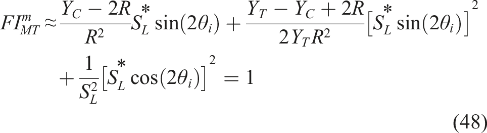
The true longitudinal shear strength,
The longitudinal tensile strength
Material parameters of composites.
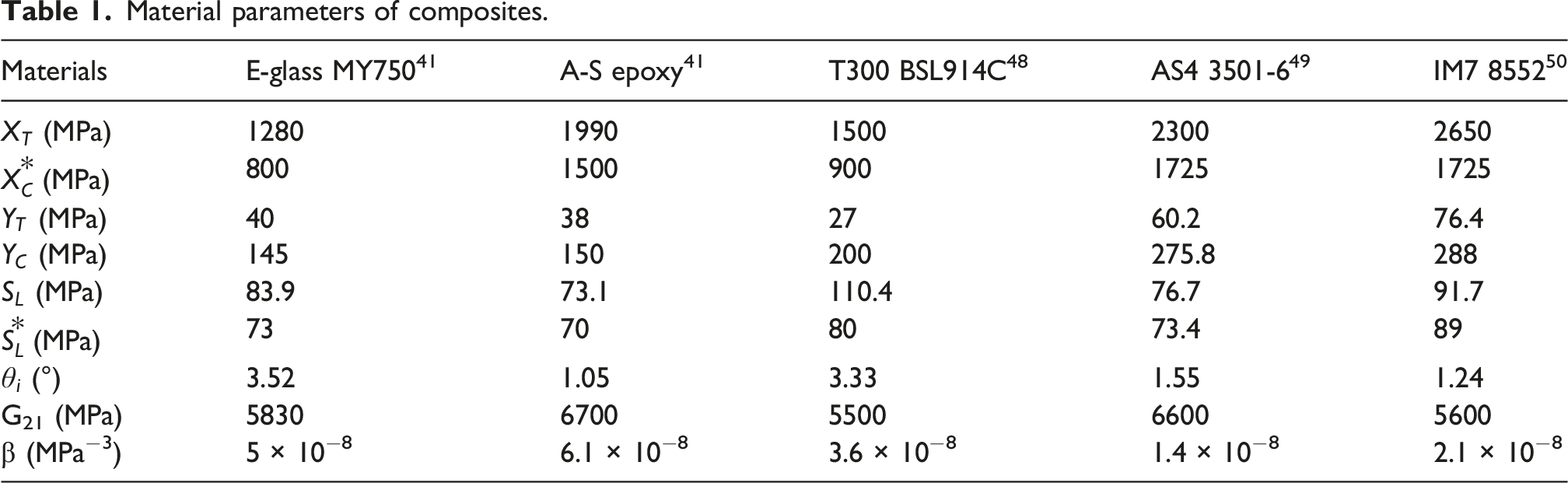
In Table 1, it should be mentioned that since the failure under longitudinal compression is caused by the matrix failure or elastic instability in localized misaligned regions, the longitudinal compressive strength measured by the experiment,
Determination of initial fiber misalignment angle
The initial misalignment angle,
Figure 4 shows the curves of equations (19) and (20) under longitudinal compressive stress of 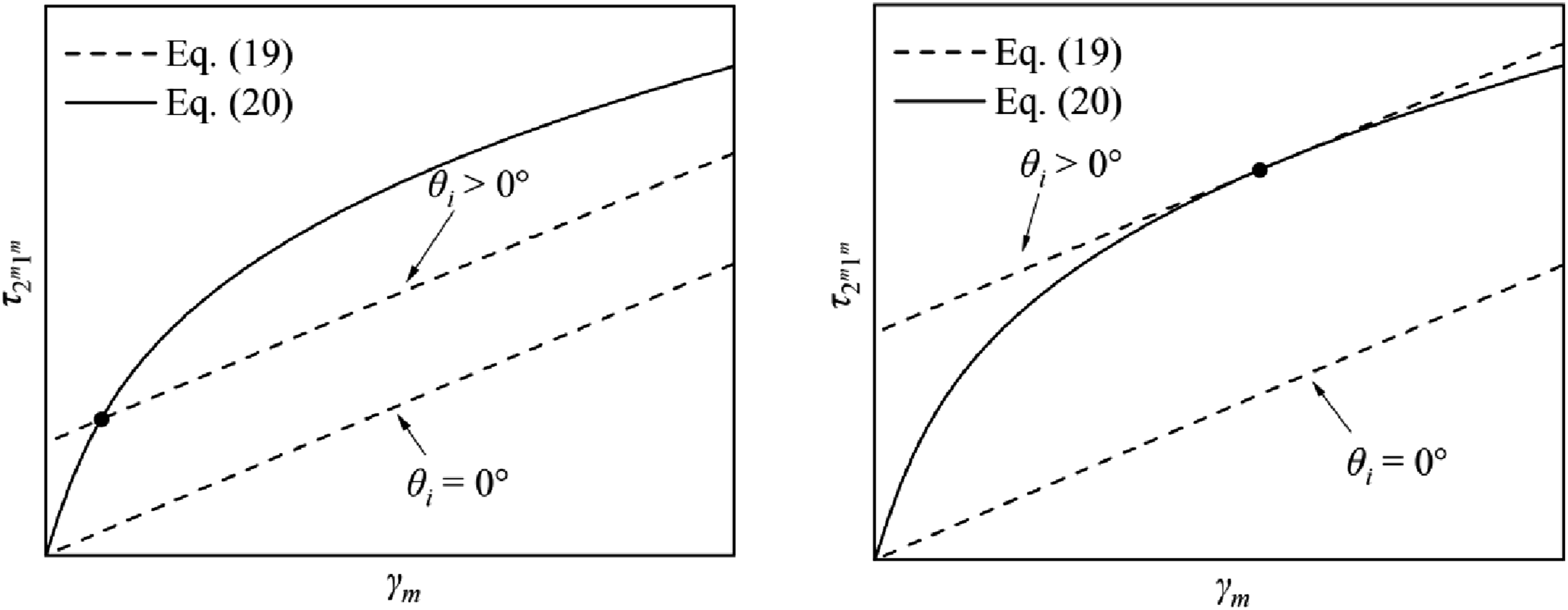
At this point, a three-dimensional failure criterion for UD composites is established. For a given composite, the basic strengths
Failure mechanism analysis
This section applies the proposed criterion to analyze the failure of the material under various stress states. The proposed criterion includes six failure modes: fiber tensile failure in the non-misaligned regions (FT), matrix tensile failure in the non-misaligned regions (MT), matrix compressive failure in the non-misaligned regions (MC), matrix tensile failure in the localized misaligned regions (MT m ), matrix compressive failure in the localized misaligned regions (MC m ), and elastic instability of the fiber in the localized misaligned regions (EI).
failure evaluation
Under the (1) In Figure 5(a), point P1 corresponds to longitudinal tensile failure. As the stress state transitions along the envelope from point P1 to P2, (2) As the stress state transitions along the envelope from point P2 to P3, (3) As the stress state transitions along the envelope from point P3 to P4, the magnitudes of the longitudinal compressive stress, (4) As the stress state transitions along the envelope from point P4 to P5, the magnitude of the longitudinal compressive stress, Evaluation for T300/BSL914 C under
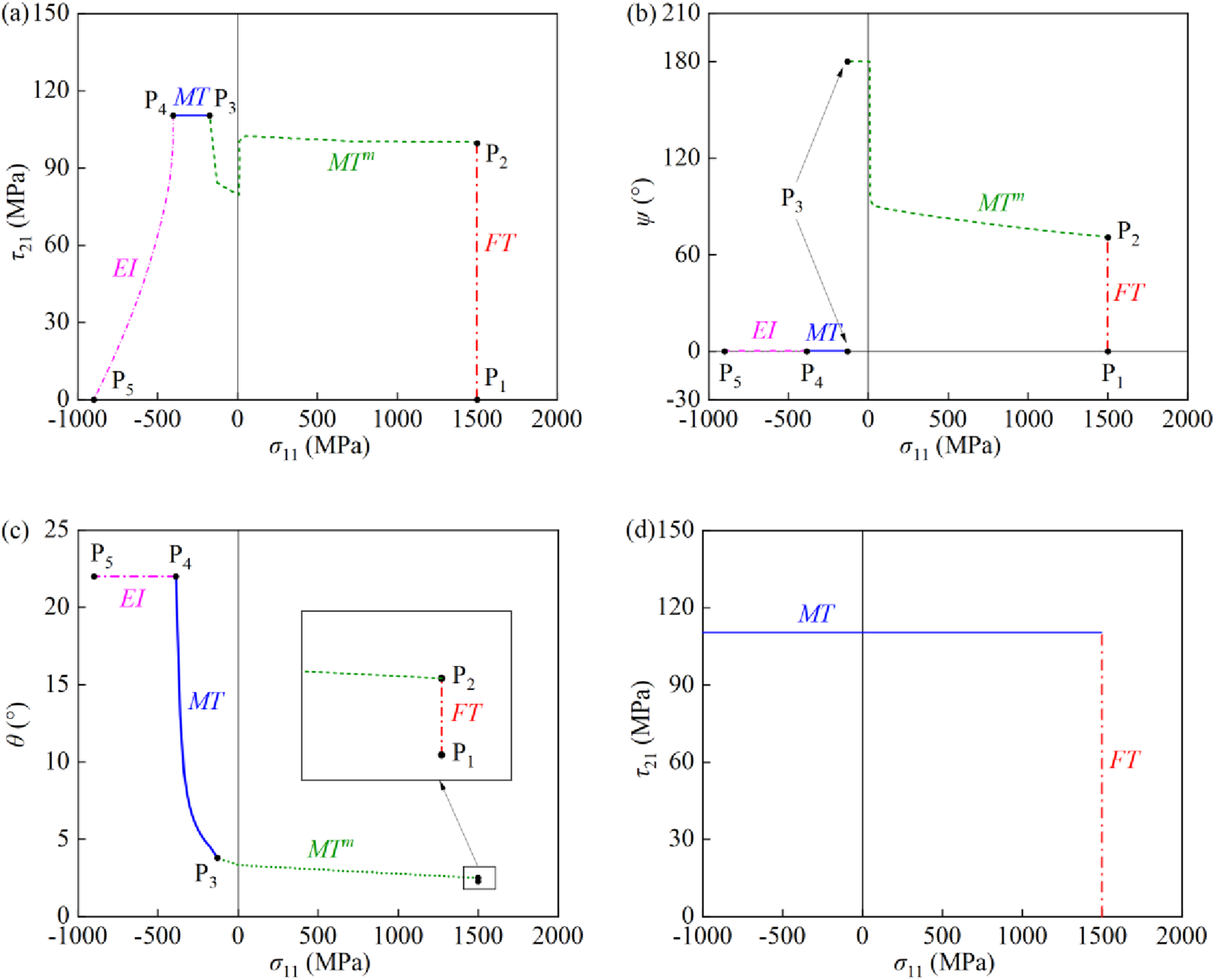
To sum up, under the The stress states in localized misaligned regions. (a) ψ = 0°; (b) ψ = 180°.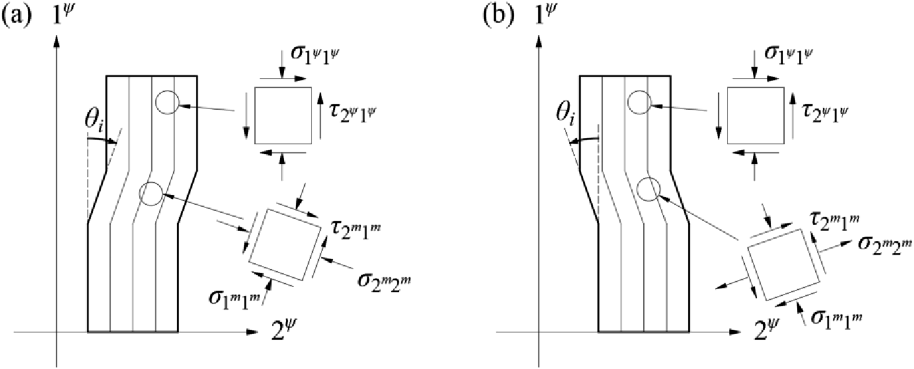
Vogler and Kyriakides
2
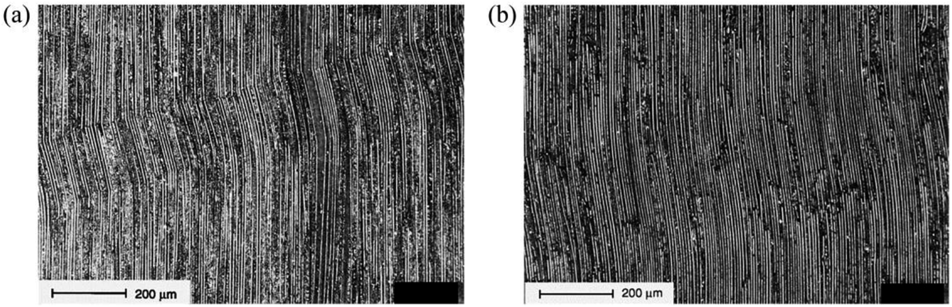
carried out tests on AS4/PEEK under the combination of longitudinal shear and compressive stresses. As depicted in Figure 7, the failure mode under high longitudinal compressive stress is different from that under low longitudinal compressive stress. Under high longitudinal compressive stress, fiber breakage occurs at the upper and lower edges of the localized kink bands; while under low longitudinal compressive stress, very few of the fibers inside the localized kink bands are broken. In addition, the fiber misalignment angle under high longitudinal compressive stress is greater than that under low longitudinal compressive stress. In order to distinguish between these two failure modes, Pinho et al.
26
proposed that for all types of composite materials, when The localized kink bands under (a) high longitudinal compressive stress, (b) low longitudinal compressive stress.
2
Vogler and Kyriakides
2
suggest that the reason why the fibers inside the kink bands do not break under low longitudinal compression stress is due to the smaller fiber misalignment angle. In addition, according to the experimental observations by Sun et al.,
7
fibers will break if the fiber misalignment angle exceeds a certain threshold. Therefore, the present study suggests that if the fiber misalignment angle,
In the
failure evaluation
Figure 8 shows the failure envelope for T300/BSL914 C under the Evaluation for T300/BSL914 C under 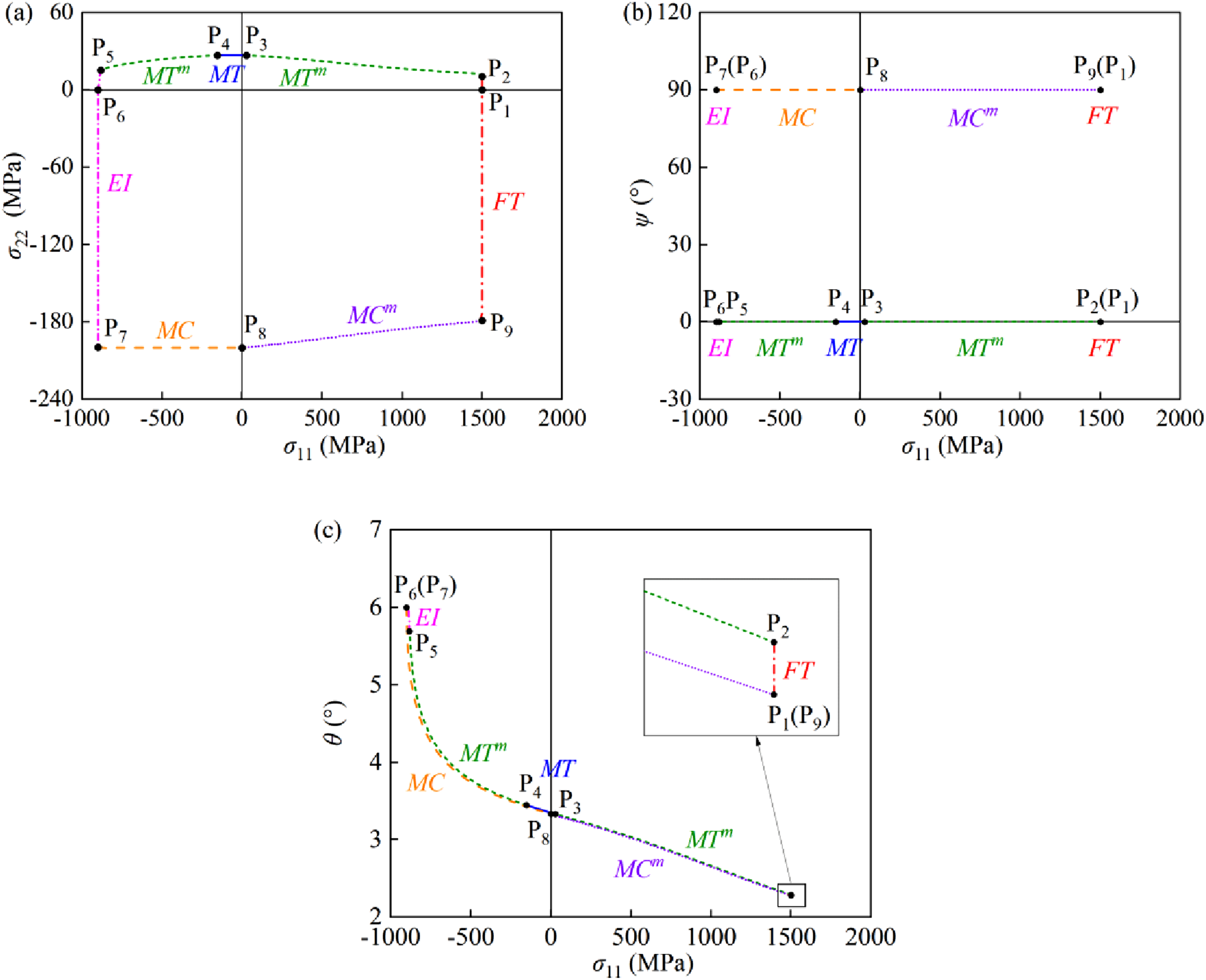
As shown in Figure 8(c), since transverse tensile stress increases
An interesting finding is that in Figure 8, EI occurs only when
failure evaluation
Under the Evaluation for T300/BSL914C under 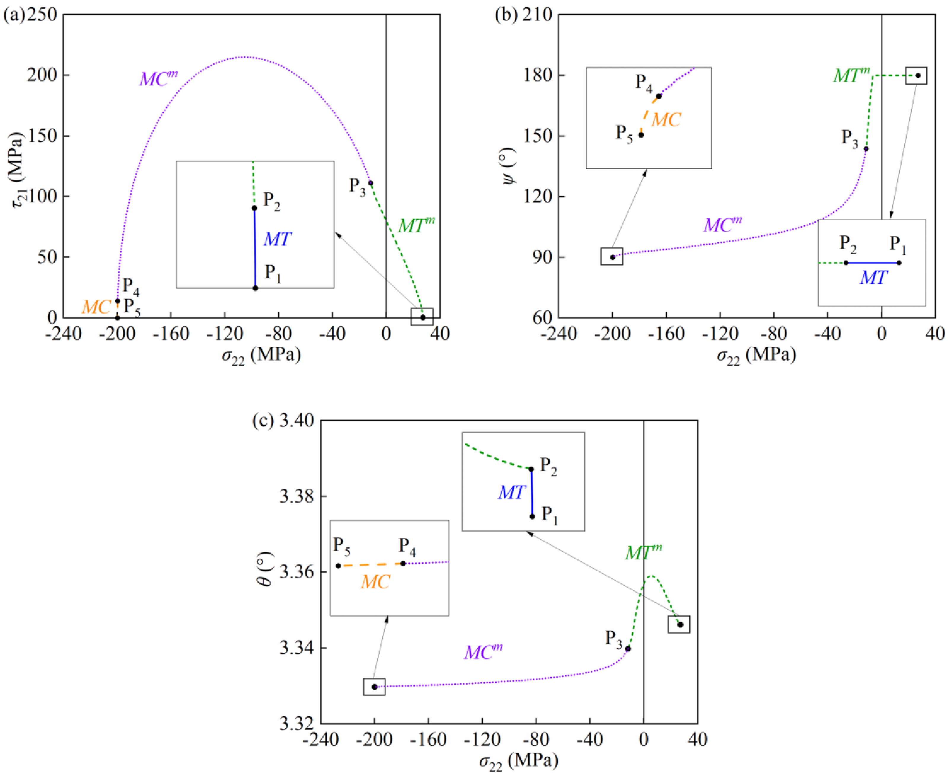
Under the
As shown in Figure 9(c), the change in
Assessment of the proposed failure criterion
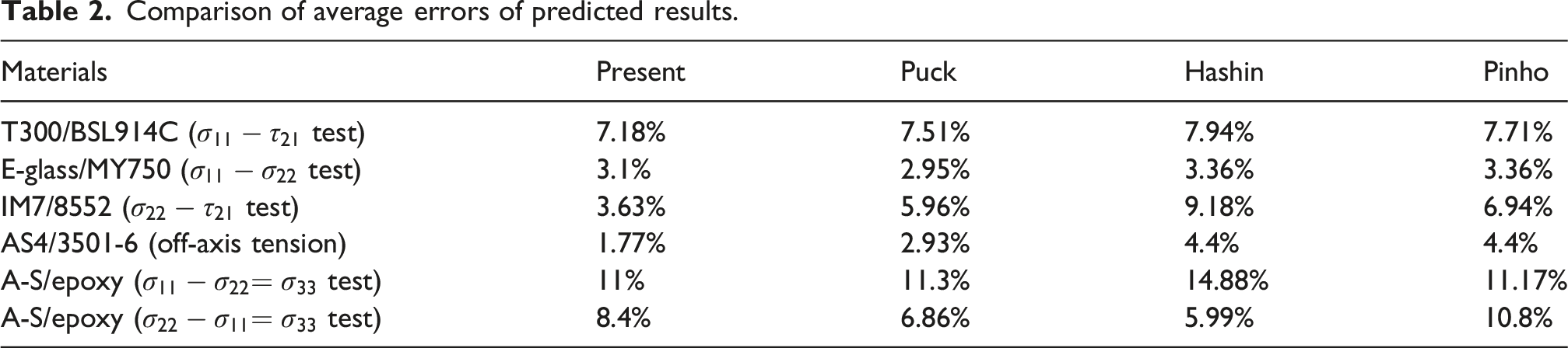
In order to verify the applicability of the proposed failure criterion, its predictions are compared with those of Hashin’s criterion, Puck’s criterion, and Pinho’s criterion, as well as with experimental data in Figure 10. The experimental data used in this section are mostly sourced from the WWFE (world-wide failure exercise),51,52 and the material properties are listed in Table 1.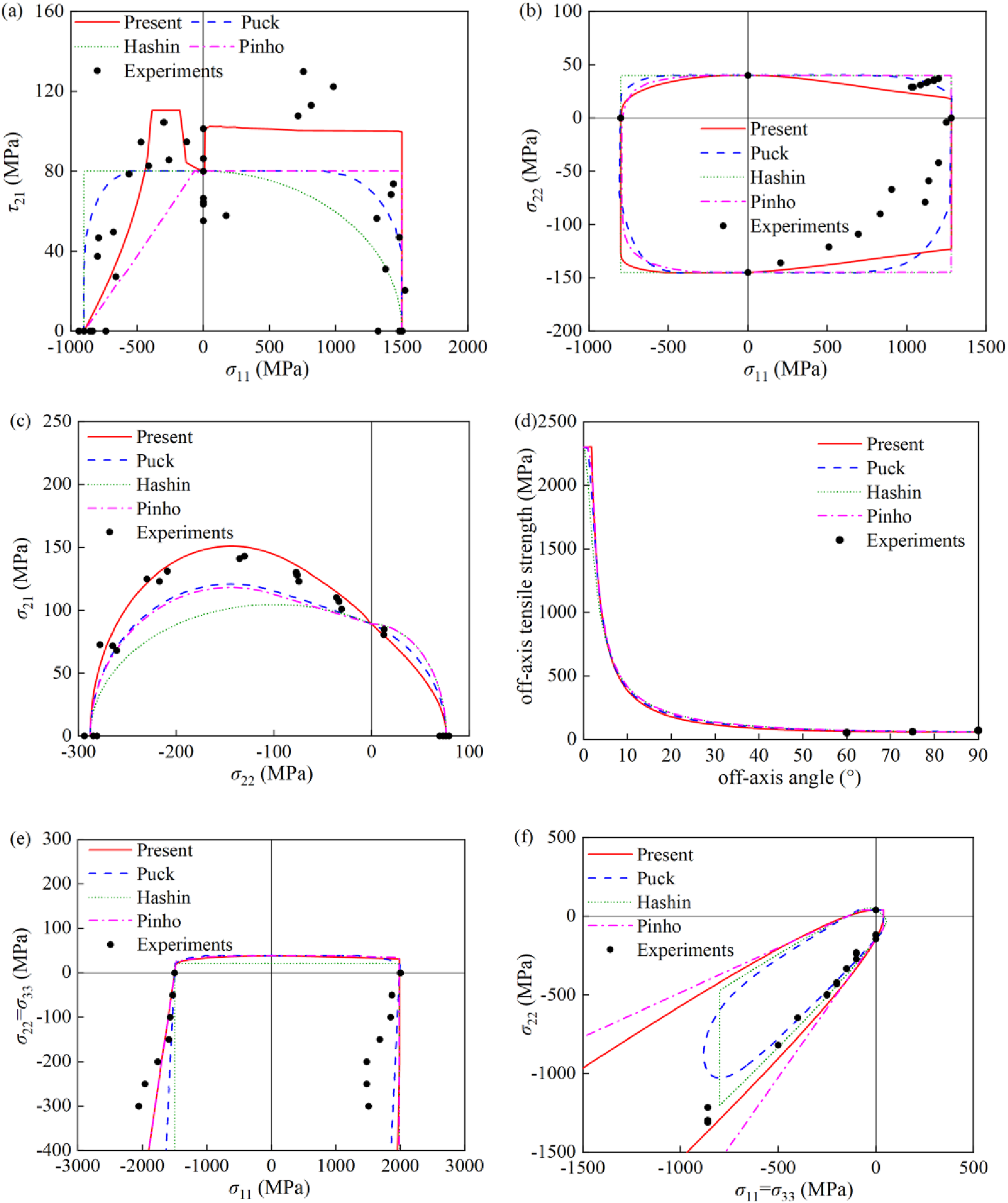
Comparison of average errors of predicted results.
Failure evaluation under
stress states
The tubes made from prepreg T300/BSL914 C carbon/epoxy were tested under combined axial tension or compression and torsion.
51
Figure 10(a) shows the test data and the
It is worth noting that the failure envelope is not smooth in the second quadrant. This is caused by the change in the angle of the kink-band plane ψ together with the transition of the failure mode as σ11 approaches zero from compression. It reflects an actual change in the dominant failure mode and is therefore physically reasonable. The failure envelope remains continuous, although it is non-smooth in this region.
Failure evaluation under
stress states
Figure 10(b) shows the
Under the combination of transverse tensile/compressive stress and longitudinal tensile stress, Puck’s criterion predicts the failure mode is matrix tensile/compressive failure. Puck’s criterion suggests that the longitudinal tensile stress reduces the fracture resistance of the matrix fracture plane. 39 Therefore, its predicted results are closer to the experimental data than Hashin’s and Pinho’s criteria. However, in Puck’s approach, the proportion of resistance reduction is determined empirically, which can be difficult to quantify without extensive experience with the specific material system. In contrast, the present criterion does not rely on any empirical parameters, and attributes the promoting effect of longitudinal tensile stress on matrix failure to failure initiation in localized misaligned regions.
Failure evaluation under
stress states
Schaefer et al.
50
carried out quasi-static tests for IM7/8552 under
Failure evaluation under off-axis tension
Daniel et al.
49
performed off-axis tensile tests on AS4/3501-6. As illustrated in Figure 10(d), the predicted strengths of the four failure criteria are close, and their predicted results are in good agreement with the test data. Unlike the other criteria, the present criterion accounts for the influence of fiber misalignment when
Failure evaluation under
stress states
Figure 10(e) shows the
Failure evaluation under
stress states
Figure 10(f) shows the
Conclusion
This study proposes a theoretical model for predicting kink-band formation, and compared to previous models, it considers the effect of the shear strain in non-misaligned regions on the fiber misalignment angle and the influence of each stress component on the angle of the kink-band plane. Based on this model, a three-dimensional failure criterion for composites is further proposed. In contrast to Pinho’s criterion, it accounts for the effect of fiber misalignment under all stress states, thereby overcoming the discontinuity problem in the failure envelope. Because the present failure criterion suggests that failure in localized misaligned regions and non-misaligned regions is competitive under any stress state, the experimentally measured basic strength may not be true. The present study corrects the experimentally measured basic strength and finds that, for most composites, the true longitudinal shear strength differs from the experimentally measured strength.
Using the proposed failure model, the failure behavior of the material under different stress states is analyzed. An interesting conclusion is that, under the
Footnotes
Funding
The authors disclosed receipt of the following financial support for the research, authorship, and/or publication of this article: This work was supported by the Joint Funds of the National Natural Science Foundation of China (Grant Nos. U25B6004, 12202066) and the Fundamental Research Funds for the Central Universities (Nos. NS2024008, NJ2024003).
Declaration of conflicting interests
The authors declared no potential conflicts of interest with respect to the research, authorship, and/or publication of this article.
Data Availability Statement
Data sharing not applicable to this article as no datasets were generated or analyzed during the current study.