
Abstract
Due to their lightweight and high-strength characteristics, composite fasteners have become one of the focal points in the field of composite material connections. This paper establishes progressive damage models for specimens with different connection methods. Through the implementation of the VUMAT subroutine based on the Hashin failure criteria, the single shear performance and damage processes of GFRP fasteners in bolt, screw, and stud connections are analyzed. The results indicate that bolts exhibit the highest single shear strength, followed by screws, with studs being the weakest, which is related to the structure of the specimens. The relative errors between the ultimate loads predicted by the finite element model and those obtained from experiments are 3.28%, 3.34%, and 5.49%, respectively. Bolts tend to approximate planar fracture characteristics, screw fracture surfaces show a pointed apex shape, while studs display stepped cracks. These findings align well with experimental results, verifying the reliability of the model.
Introduction
Fiber-reinforced polymer composites, due to their exceptional properties, are widely used in various connections in fields like aerospace.1–3 Metal bolts, because of their heavy weight and susceptibility to corrosion and oxidation,4–8 have been replaced by fiber composite fasteners that offer a high strength-to-weight ratio and multifunctionality. Therefore, research on fiber-reinforced polymer (FRP) fasteners is crucial, particularly for glass fiber-reinforced polymer (GFRP) fasteners that possess wave-transmitting capabilities.
Currently, composite material connections primarily include adhesive bonding, 9 bolted connections, 10 screwed connections, 11 and bonded bolt connections, 12 with most using metal fasteners. Among the various connection methods, threaded connections are favored for their cost-effectiveness, ease of maintenance, and simplicity in disassembly.13–15 However, existing studies have largely focused on metal fasteners or composite structures employing metallic fastening components. For example, Zhang et al. 16 analyzed the damage in CARALL structures with bolted connections under quasi-static loads. Lin et al. 17 refined a 3D model of composite bolted joints and analyzed the influence of bolt preload and washer type on the initial assembly-induced damage. Zhang et al. 18 studied the shear performance of high-strength bolted connections in prefabricated steel-concrete composite beams, concluding that the shear bearing capacity of bolted connections mainly depends on the bolt diameter, bolt tensile strength, and concrete strength. Diana 19 conducted experimental studies on the connection performance of bolts made from three materials: stainless steel (SS), basalt fiber-reinforced polymer (BFRP), and hybrid steel fiber-reinforced polymer (HSFRP). Zhang et al. 20 explored the effects of different laminate sequences and connection types on the tensile performance and failure behavior of composites.
Due to the anisotropic nature and complex fiber architecture of fiber-reinforced composites,21–24 the failure mechanisms of FRP fasteners differ significantly from those of metal fasteners. Thus, there has been considerable attention on the strength, failure modes, and influencing factors of fiber-reinforced fasteners. For instance, Yao et al. 25 studied unidirectional carbon fiber reinforced polyetheretherketone (CF/PEEK) fasteners and found that, under certain conditions, lighter fiber-reinforced polymer fasteners can replace metal fasteners to meet strength requirements. Ren et al. 26 investigated the mechanical behavior and damage mechanisms of T1000/BMI composite bolted joints under thermo-mechanical cycling from −80°C to 80°C. Li et al. 27 examined the long-term performance of glass fiber-reinforced polymer (GFRP) bolts under harsh environments (such as hot-humid and stress corrosion). The results indicated that the coupling effect of environmental conditions and stress significantly reduces the mechanical performance of GFRP bolts and accelerates their creep failure. Zhang et al. 28 studied the tensile performance of laminated braided plain and twill woven GFRP bolts, finding that laminated plain woven bolts and threads exhibit higher tensile strength compared to twill woven ones, and reducing the loading rate within a certain range can improve the tensile strength of the threads. However, most of these studies primarily focus on specific material systems or single connection configurations, while systematic comparative investigations into the mechanical behavior differences of composite fasteners under various connection modes remain relatively limited.
In summary, current research has primarily focused on the connection performance of metal fasteners, while studies on composite fasteners and their corresponding connection behavior remain insufficient. In addition, systematic comparative investigations of specimens with different connection configurations are still lacking. Therefore, in this study, high-temperature laminated woven glass fiber-reinforced polymer (GFRP) composites were selected to manufacture composite fasteners. By combining numerical simulation with experimental approaches, the single-shear mechanical behavior, damage evolution process, and failure mechanisms of GFRP fasteners under three different connection modes—bolt, screw, and stud connections—were systematically investigated. Through comparative analyses of load-bearing capacity, damage characteristics, and failure modes under different connection configurations, this work aims to provide theoretical references and experimental support for the design of lightweight, high-strength composite connection structures.
GFRP fasteners single shear test design
Specimen preparation and parameters
The experiment was conducted in accordance with ASTM D5961/D5961 M
29
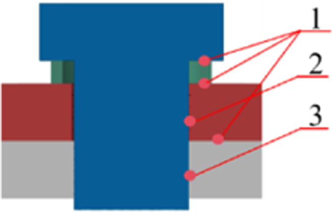
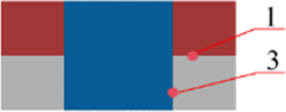
standards, with detailed dimensions of each component depicted in Figure 1. In the single shear test, to ensure the symmetry of clamping loads during the experiment, the upper and lower grips need to be maintained in the same plane. A 5 mm thick glass fiber plate was selected as a compensating sheet, and it was bonded to the connected parts using Ergo1309 high-strength AB adhesive. The assembly was clamped and left to cure for 24 h until the adhesive was fully set. Subsequently, the fasteners were tightened using a torque wrench and other tools. Specifically, for bolt connections, the connected parts had through holes; for screw connections, the upper and lower connected parts had through and threaded holes, respectively; and for stud connections, the connected parts had threaded holes. Relevant dimensions and joint types of specimens for three connection methods.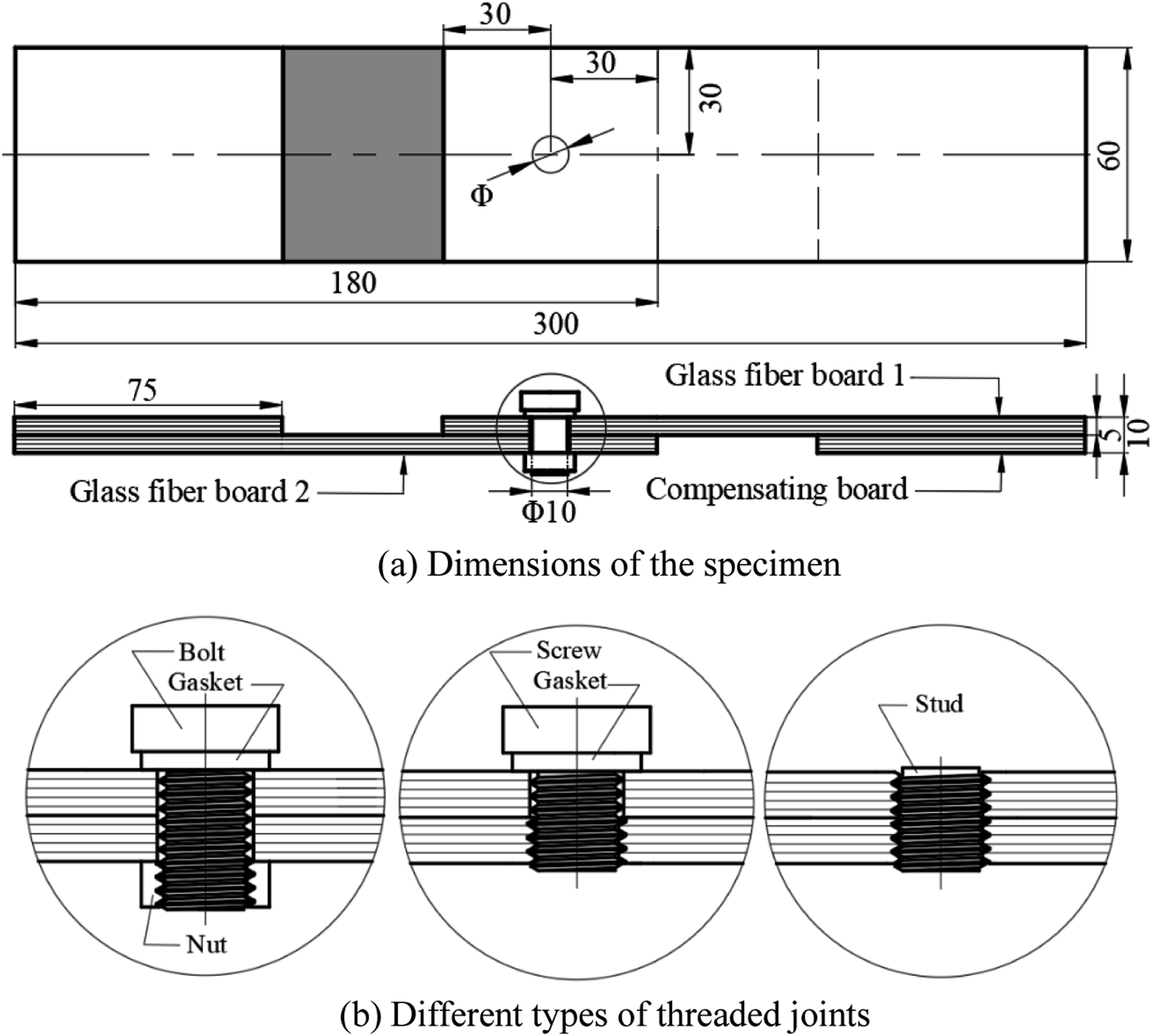
The fasteners used in this study are made from lightweight, high-strength woven glass fiber fabric, known for its excellent wave-transmitting properties.30,31 This fabric is woven by interlacing warp and weft yarns in an alternating pattern at each fiber bundle. Single-layer prepregs are stacked in the Y-direction as shown in Figure 2(a) to form a preform. After vacuuming, the preform is laminated and cured under high temperature and pressure to produce GFRP composite material. Finally, the fasteners are machined along the Y-axis to achieve their final form. Figure 2(c) provides a schematic of the bolt, while Figure 2(d) illustrates the internal microstructure of the woven fastener. Schematic diagram of fasteners forming: (a) preform; (b) GFRP rod; (c) GFRP fasteners; (d) fiber structure under microscope.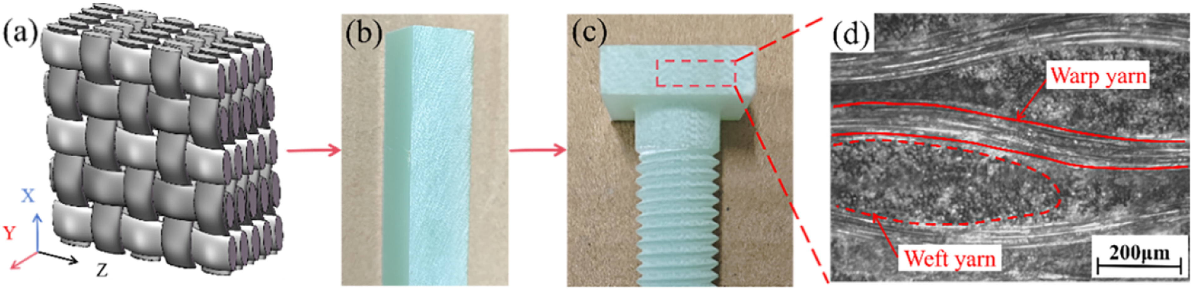
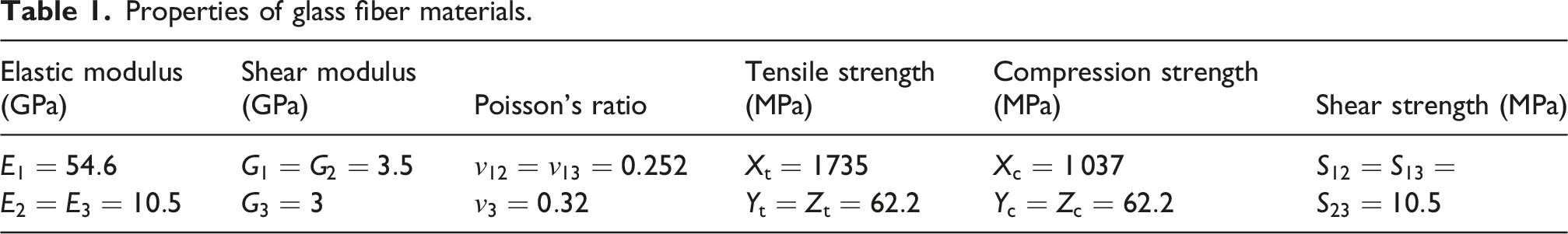
Properties of glass fiber materials.
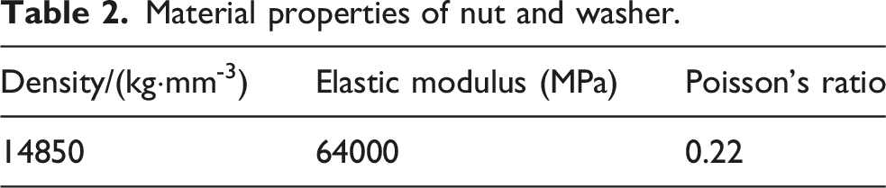
Material properties of nut and washer.
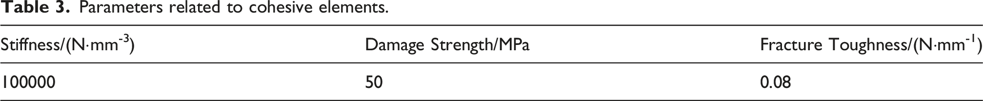
Parameters related to cohesive elements.
Single shear test method for GFRP fasteners
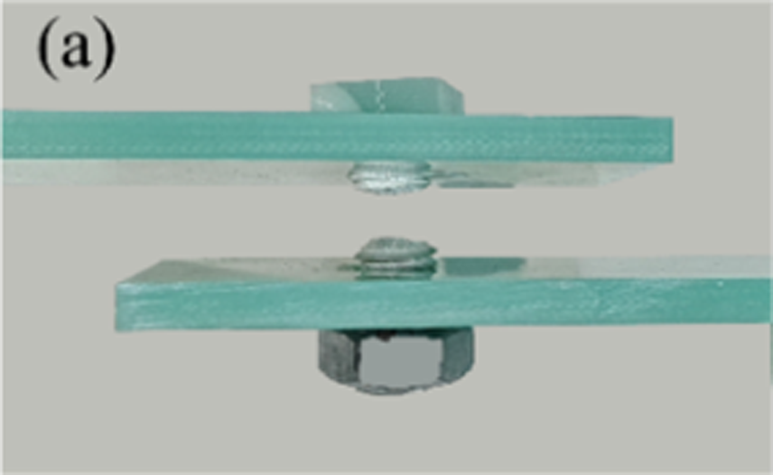
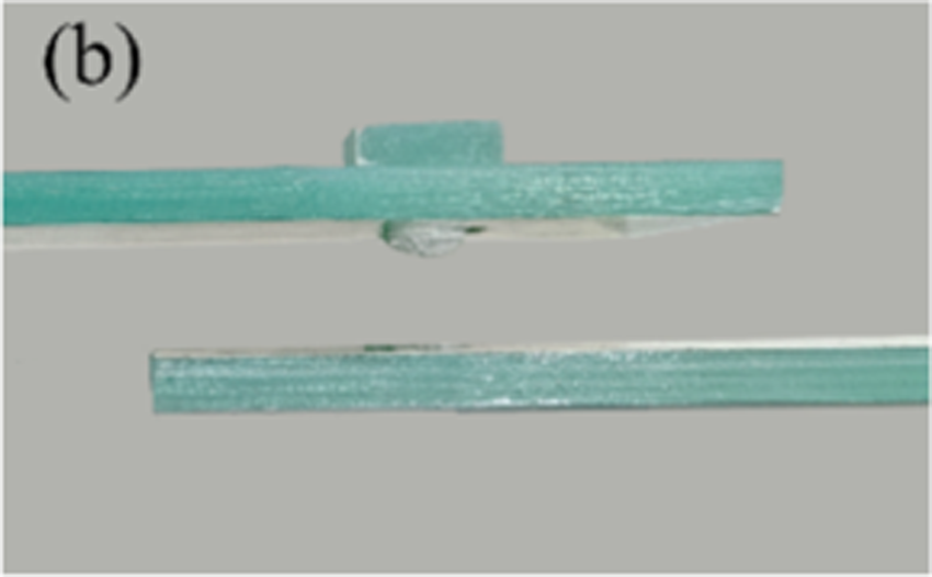
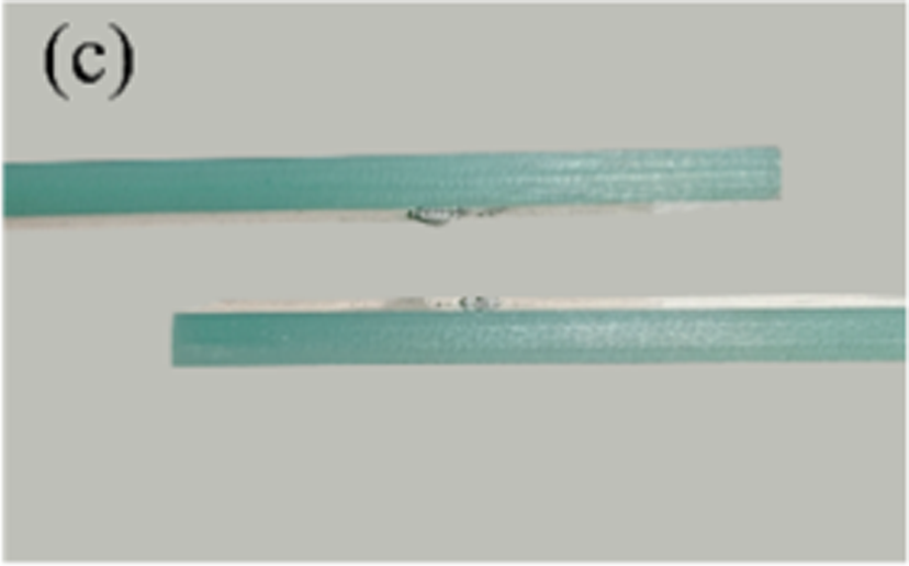
Single shear tests on GFRP fasteners were carried out using a Shimadzu AGS-X universal testing machine. To ensure the accuracy of the experiments, five parallel specimens were prepared for each connection method. The tests were performed under quasi-static loading conditions at a displacement rate of 2 mm/min, with the maximum load set at 50 kN. The preload is 8 kN, the environment is at room temperature, and the threads are manufactured in accordance with standard metric thread specifications. The specimens are machined using CNC equipment with dimensional tolerances within +0.05 mm. In the hole-fit assembly, the clearance between the fastener (M10) and the hole is controlled within 0.2 mm. The detailed experimental setup is depicted in Figure 3. GFRP fasteners single shear experimental device: (a) bolt connection; (b) screw connection; (c) stud connection.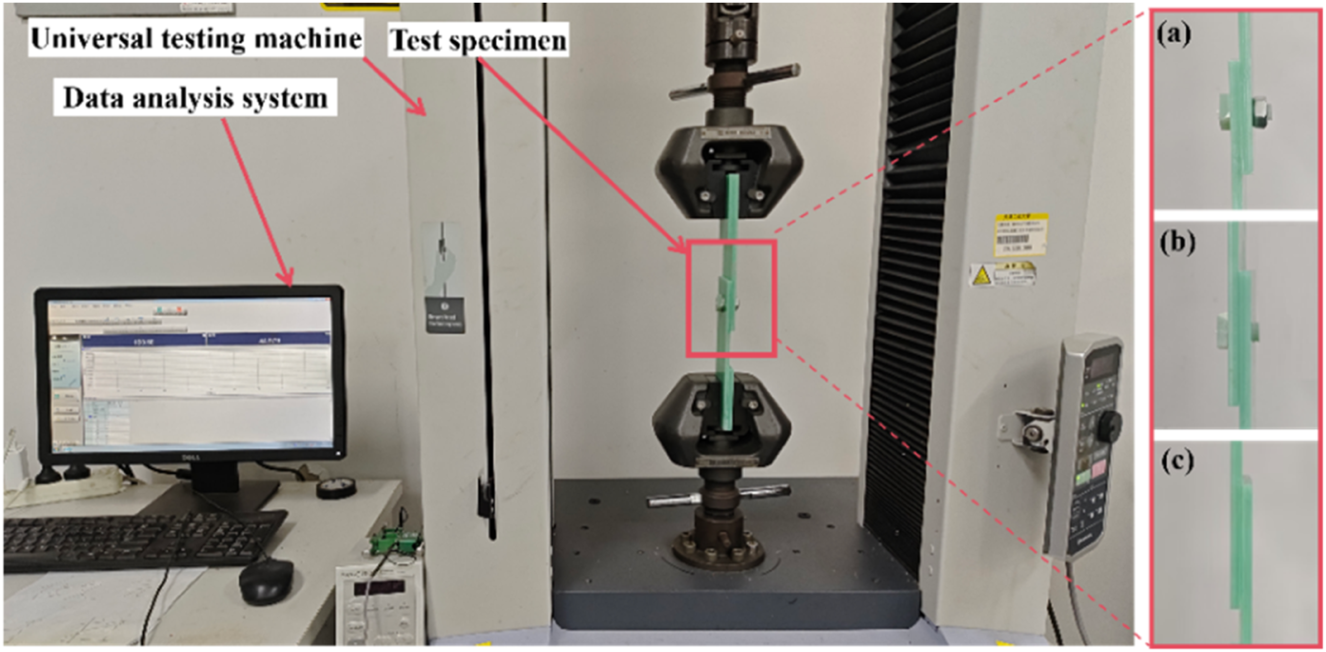
Single shear tests and numerical simulation
Damage assessment of models
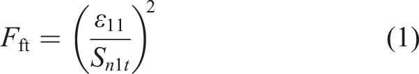
Due to the anisotropic nature of fiber-reinforced composites, accurately simulating the progressive damage and failure behavior of fibers during testing is crucial. This study employs the Hashin failure criteria, implemented through a FORTRAN script, to model the complex failure processes. The model considers multiple failure modes, including fiber tension, fiber compression, matrix tension, and matrix compression.
33
These criteria are used to predict the progressive damage behavior of the fiber-reinforced composite materials. The implementation is carried out in ABAQUS using the VUMAT subroutine. (a) Fiber tensile failure: when the fiber-direction strain (b) Fiber compression failure: when the fiber-direction strain (c) Matrix tensile failure: when the sum of transverse strains (d) Matrix compression failure: when the sum of transverse strains
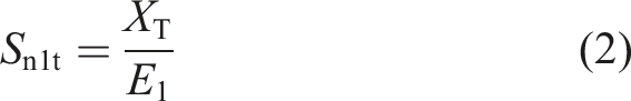
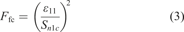
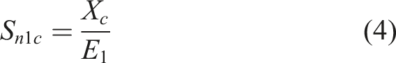
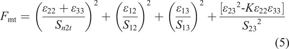
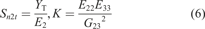
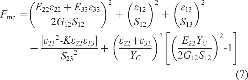
In the above expression,
Once failure conditions are met, material damage initiates. Different stiffness reduction coefficients are assigned corresponding to fiber tension, fiber compression, matrix tension and matrix compression failure modes to reflect gradual material performance degradation and simulate damage evolution. This model does not adopt element deletion rules based on damage variables. Failed elements remain in the calculation with residual stiffness retained.
Numerical model for single shear specimens
Abaqus was employed to build finite-element models of the three connection types shown in Figure 4. Figure 4(a) presents a partial view of the bolt connection model, which comprises five parts: bolt, washer, nut and adherends. Figure 4(b) corresponds to the screw connection, consisting of four parts: screw, washer and adherends. Figure 4(c) illustrates stud connection model, containing only the stud and the two adherends. All component dimensions in the models match those of the experimental specimens exactly. Fasteners were meshed with C3D4 tetrahedral elements of 1 mm34,35 size, while the remaining parts used 1 mm C3D8R hexahedral elements. Washers and nuts were assigned a 1 mm mesh, and the adherends a 1.5 mm mesh. To capture damage evolution clearly, the overlap region of the adherends was refined to an average element size of 1 mm. Finite-element models of single shear specimens: (a) bolt connection; (b) screw connection; (c) stud connection.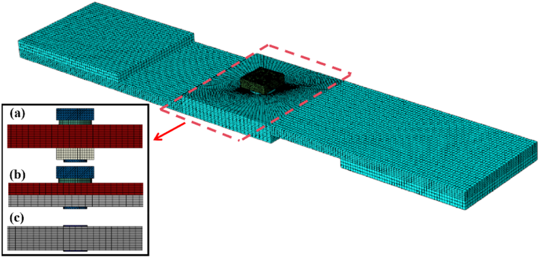
During the single-shear process, washers and nuts were modelled as analytical rigid bodies. As load increases, slip develops and material damage progresses, the contact relationships between components evolve accordingly. Surface-to-surface contact was therefore adopted to capture the interaction behavior of all parts. Tangential behavior was defined as penalty contact with a friction coefficient of 0.3, while normal behavior was set as “hard” contact. To improve computational efficiency, bolt-to-nut and bolt-to-washer interfaces in the bolted joint were tied; similarly, screw-to-washer contact was tied in the screwed joint.
To avoid excessive iterations and potential convergence difficulties, the models were solved with the ABAQUS/Explicit solver. Fixed constraints were applied to the left-end adherend and compensation plate to replicate the clamping condition in the experiment, while a tensile displacement was imposed on the right-end adherend.
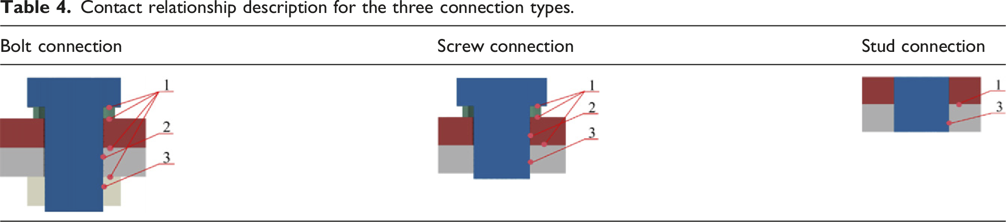
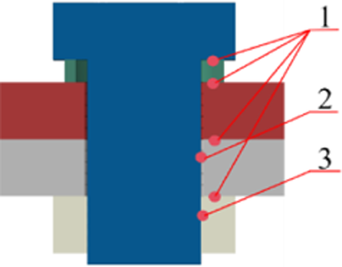
Contact relationship description for the three connection types.
Results and discussion
Single shear strength analysis of three fastener types
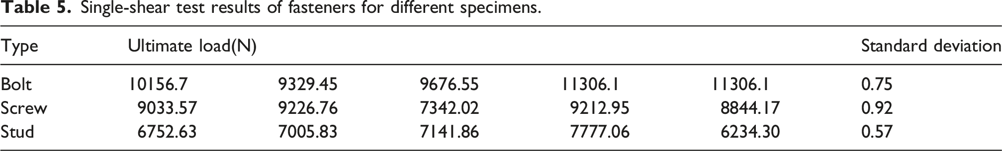
Figure 5 shows the distribution of failure-load data for each GFRP fastener specimen obtained from the single-shear experiments; the abscissa denotes specimens numbered 1-5. Black, blue and red dashed lines indicate the average failure loads of bolted, screwed and studded specimens, namely 10143.34 N, 8731.89 N and 6982.34 N, respectively. Meanwhile, Table 5 presents the detailed experimental values for each group of the three specimen types. Comparison of failure loads for different fasteners. Single-shear test results of fasteners for different specimens.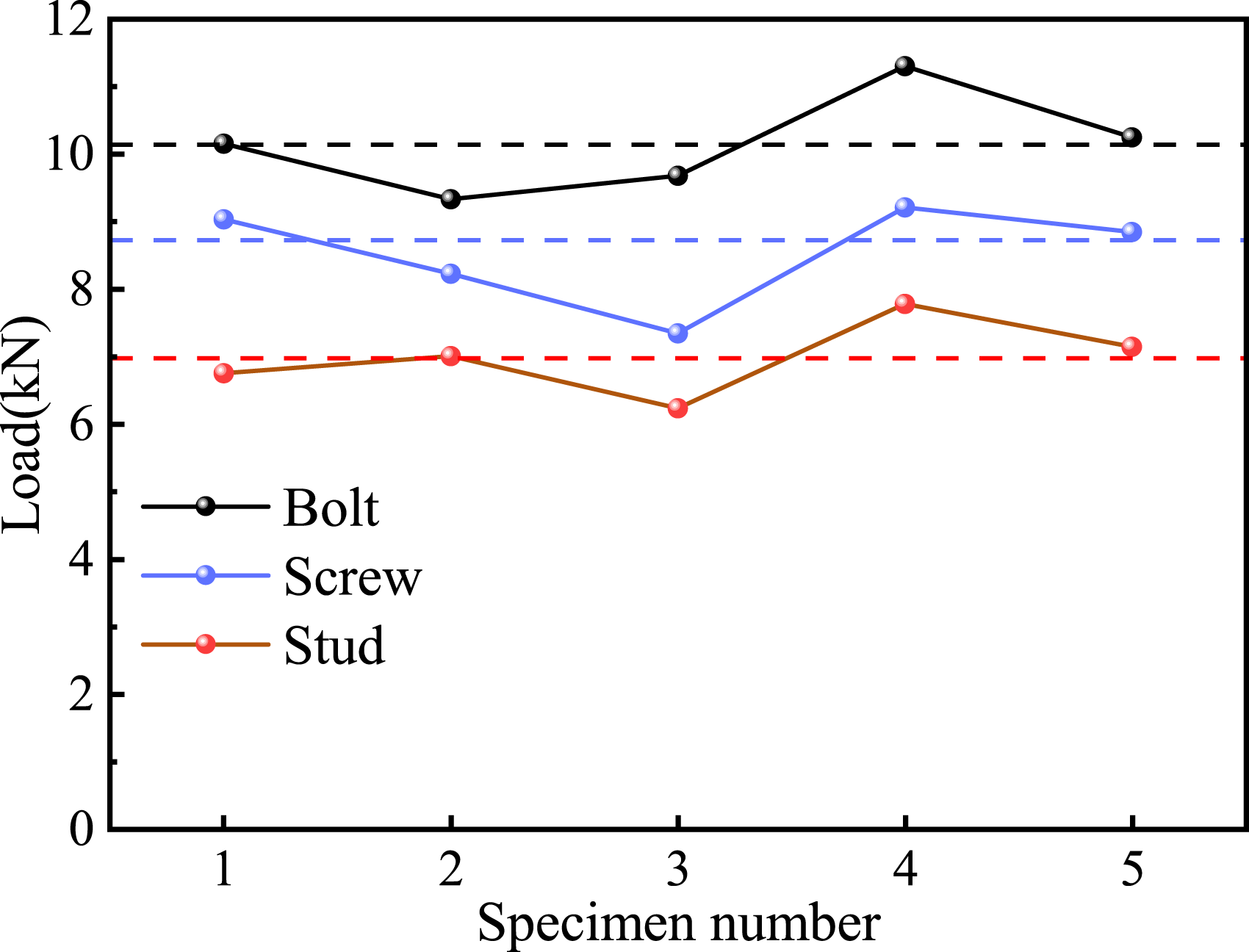
In the bolted connection, both composite plates contain through-holes that are clearance-fitted to the bolt shank; under load the bolt underwent a slight tilt. During the subsequent fracture process, significant tensile stresses acted in addition to shear. In a screw connection, the upper component consists of a clearance hole plate while the lower component is a threaded hole plate, combining a clearance fit with threaded engagement. After the application of force, the screw undergoes slight inclination. Failure develops under a mixed tensile-and-shear stress state. The stud connection employs threaded holes in both plates; the stud remains vertical during loading. Its fracture is governed primarily by shear stress, with tensile stress remained at a low level.
Bolt connection exhibit the highest mechanical performance, while stud connection are the weakest, a trend that is highly consistent. The small scatter in failure load for each connection type demonstrates good repeatability and confirms the significant influence of connection type on load-bearing capacity.
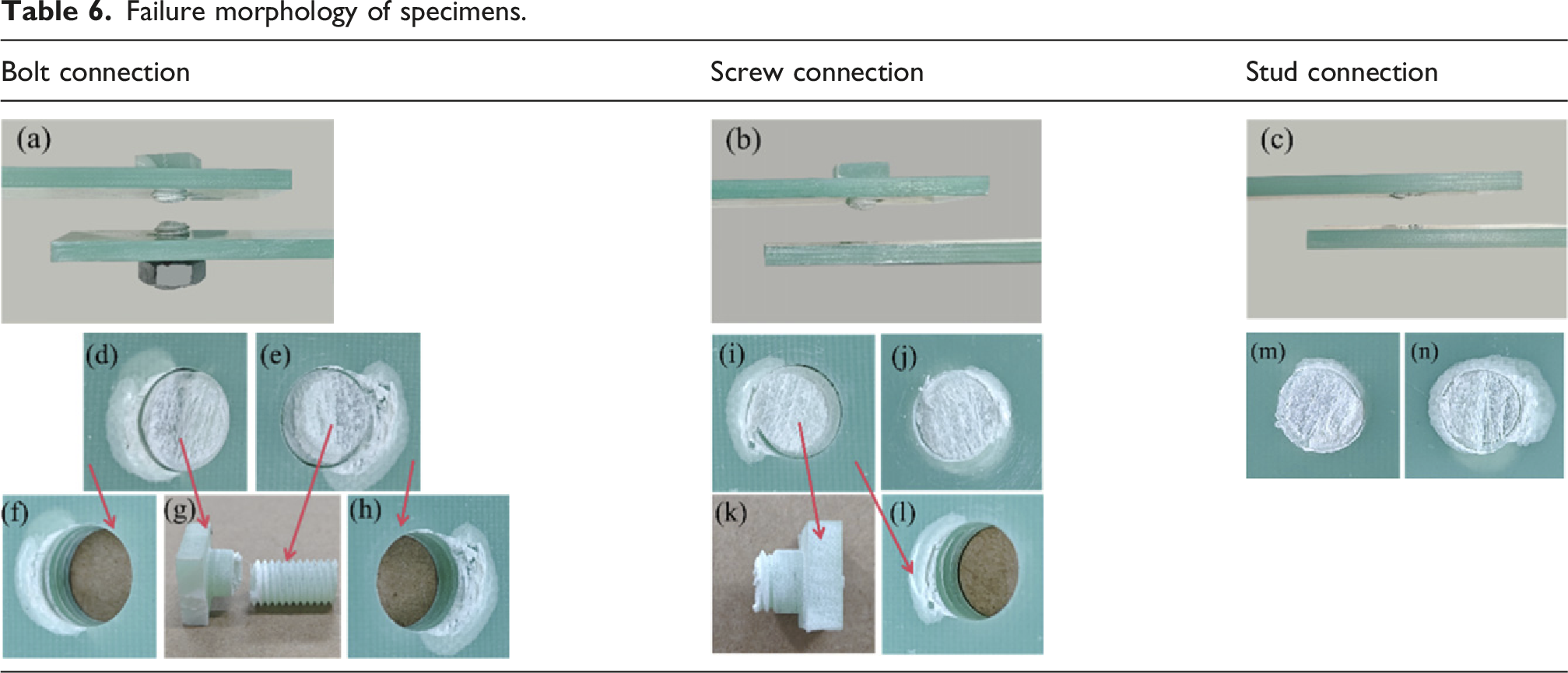
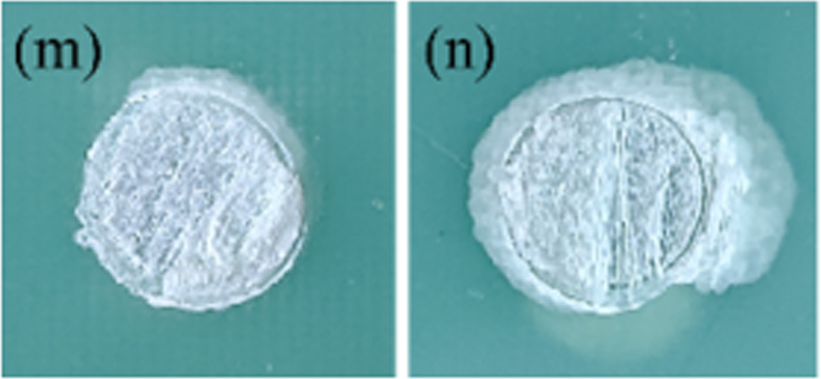
Failure morphology of specimens.
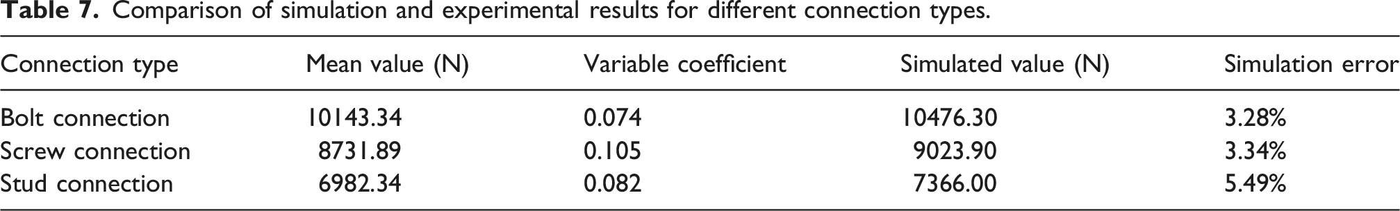
Numerical simulations were conducted for the three connection types. Figure 6(a)–(c) compare the experimental and simulated load-displacement curves for bolted, screwed and studded fasteners, respectively. All curves rise monotonically, and the close agreement between simulation and experiment confirms that the finite-element model reliably reproduces the mechanical behavior of such connections. The different curve shapes reflect variations in specimen geometry and joint type: bolted joints are fully through-hole, screwed joints are through-hole on top and tapped below, while studded joints are fully tapped. Contact assignments in the simulations are presents in Table 3. The screwed joint shows a steeper initial load increase due to its asymmetric configuration. Single shear load–displacement curves for fasteners: (a) bolt connection; (b) screw connection; (c) stud connection.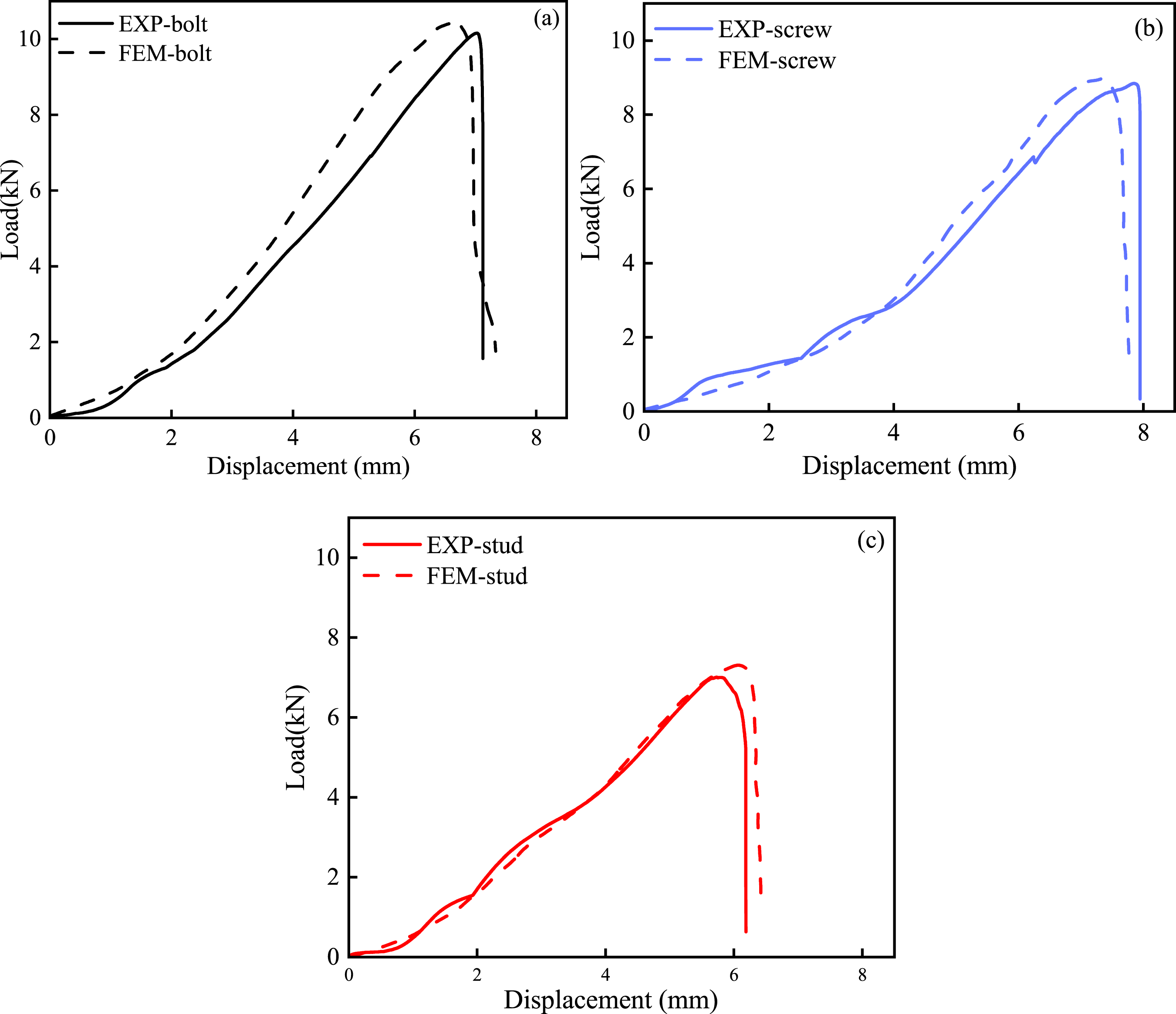
Comparison of simulation and experimental results for different connection types.
The average single shear strengths of the three fasteners were calculated and are presented in Figure 7. The bolt exhibits a strength of 172.92 MPa, the screw 150.58 MPa and the stud 120.41 MPa. Both the numerical simulation and the experiment show that the bolt is the strongest, the screw is intermediate and the stud is the weakest, a trend attributable to the different structural configurations of the specimens. Comparison of shear strengths for three types of fasteners.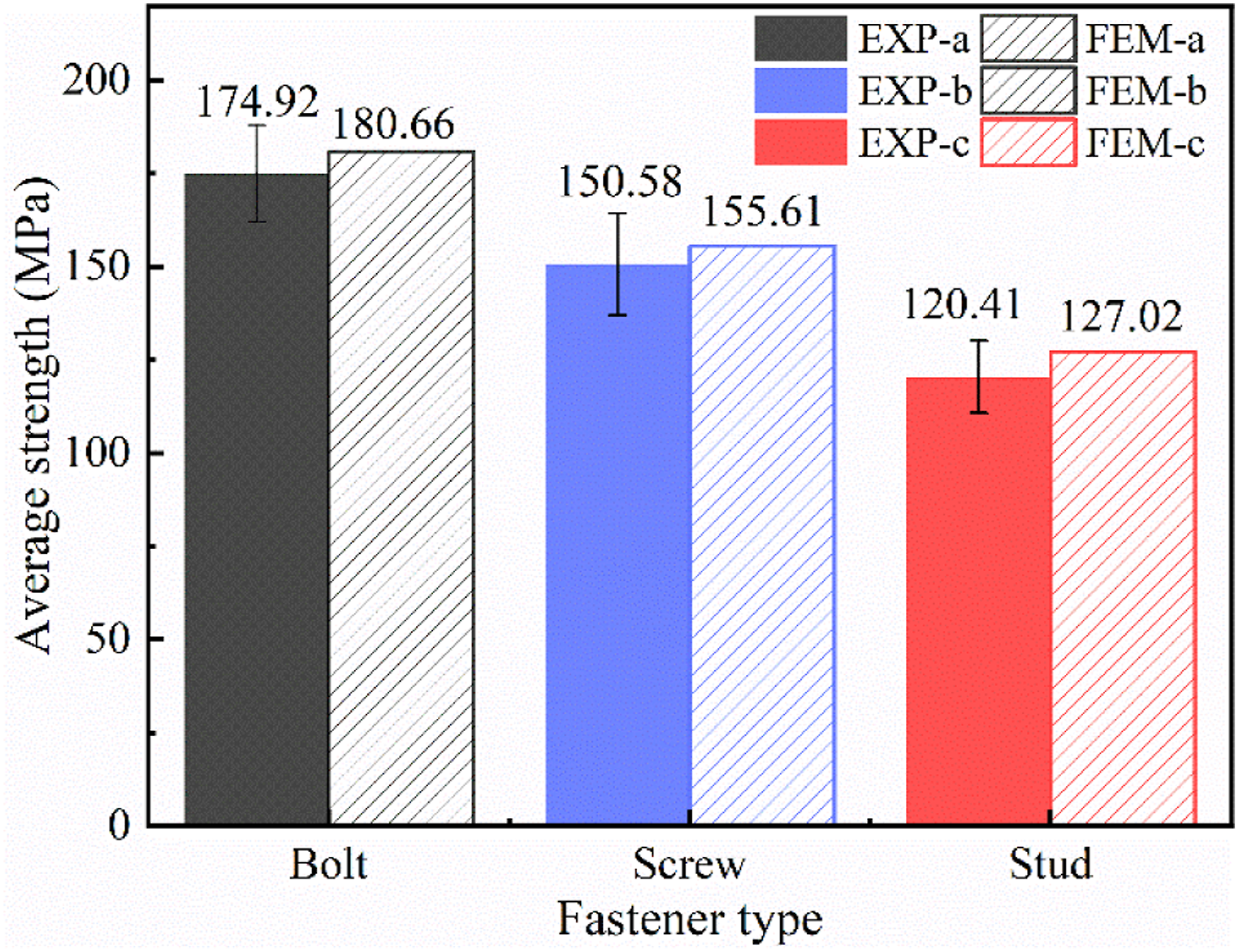
Stress transfer and damage analysis of three single shear fastener types
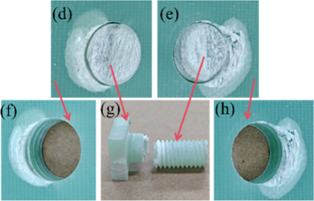
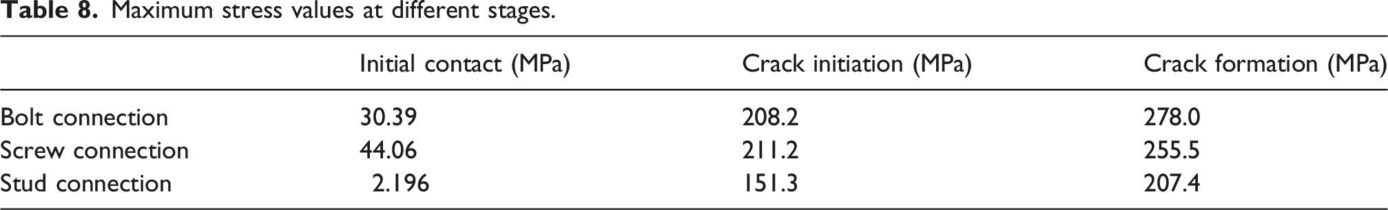
The stress transfer processes during single shear simulation for bolt, screw and stud connections are illustrated in Figure 8, arranged from top to bottom as the initial stress transfer stage, the damage initiation stage and the final failure stage. The figure clearly shows the stress states of the specimens at each stage. Stress transfer process for different connection types.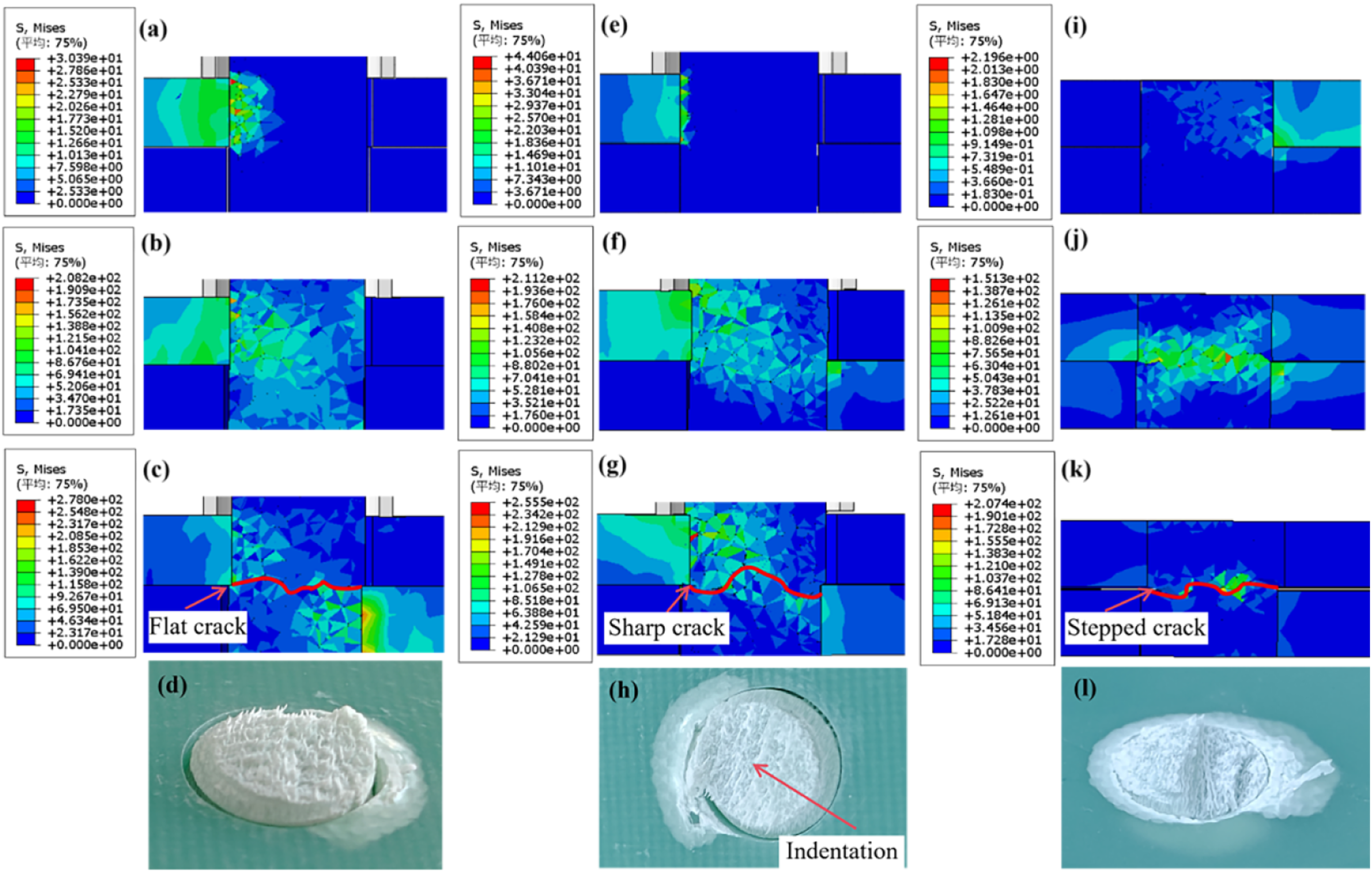
In Figure 8(a)–(c) depict the stress transfer process in the bolt connection. After the start of single shear loading, the adherend on the tension side begins to move; once the left side of the bolt contacts the hole wall, load is transferred. Stress then gradually diffuses into the bolt itself. Figure 8(b) shows the bolt crack initiation stage, where cracks appear near the adherend contact surface and eventually form the planar fracture surface marked by the red line in Figure 8(c). Figure 8(d) presents the fracture appearance, indicating relatively uniform damage and a planar fracture surface.
Figure 8(e)–(g) illustrate the stress transfer process in the screw connection. Stress transfer in this model is slower than in the bolted joint, and the stress level at initial crack appearance is lower than that in the bolted joint at the same stage. As the single shear test proceeds, a conical fracture surface marked by the red line in Figure 8(g) is eventually formed. Figure 8(h) shows the fracture surface feature of the experimental specimen, consistent with the fracture characteristics of the single-shear model.
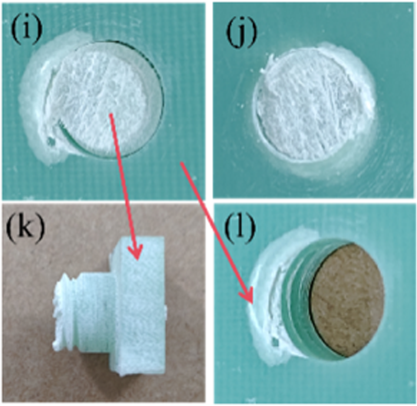
Figure 8(i)–(k) depict the stress transfer process in the stud connection. Unlike the previous two connections, the stud is in full contact with the hole wall; during tension, stress first appears on the right side of the fastener and then gradually transfers to the left, as shown in Figure 8(i). The stress-transfer region remains confined to a very small zone above and below the contact surface, eventually forming the stepped fracture surface marked in Figure 8(k). Figure 8(l) shows the stepped fracture produced in the experimental specimen.
Maximum stress values at different stages.
Stress distribution around the tension-side hole wall of adherends
Stress distribution around the tension-side hole wall at ultimate load.
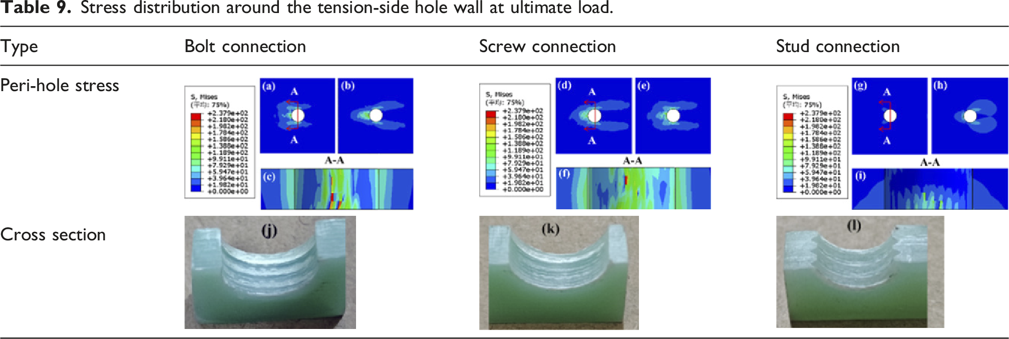
The differences in peri-hole and hole-wall damage among the three types of specimens fundamentally arise from their distinct connection structural characteristics.
In bolted joints, both the upper and lower connected parts use through-hole designs, resulting in an assembly clearance between the fastener and the hole wall at the beginning of loading. Under external force, the limited contact area between the fastener and hole wall causes a relatively broad stress distribution, which contributes to load-bearing capacity. However, fastener tilting leads to locally elevated peak stresses, with the maximum von Mises stress exceeding 238 MPa.
In screwed joints, the upper layer remains a through-hole structure, while the lower threaded engagement provides binding restraint. This suppresses fastener tilting, improves stress distribution, and reduces stress concentration. Compared with bolted joints, the hole-wall stress distribution is broader and more uniform, as shown in Table 5(f), where only one region exceeds 238 MPa.
In stud joints, the fastener is tightly engaged with the hole wall without clearance, forming surface contact. This enables earlier load transfer and provides greater fixation, effectively minimizing fastener tilting and stress concentration during tensile loading. As shown in Table 5(i), the hole-wall stress is more uniformly distributed near the contact surface of the connected parts, primarily ranging from 59.47 MPa to 118.9 MPa.
Damage analysis around the tension-side hole wall of adherends
Following the four damage criteria described in Damage assessment of models—fiber tensile, fiber compression, matrix tensile, and matrix compression, Figure 9 presents the damage state at the limit load in the numerical model. In the figure, SDV11 denotes fiber tensile damage, SDV13 denotes fiber compression damage, SDV14 denotes matrix tensile damage, and SDV15 denotes matrix compression damage. When each criterion is greater than or equal to 1, the corresponding failure mode occurs; values in the range 0-1 indicate progressive or partial damage. Peri-hole damage of joined components under three connection methods.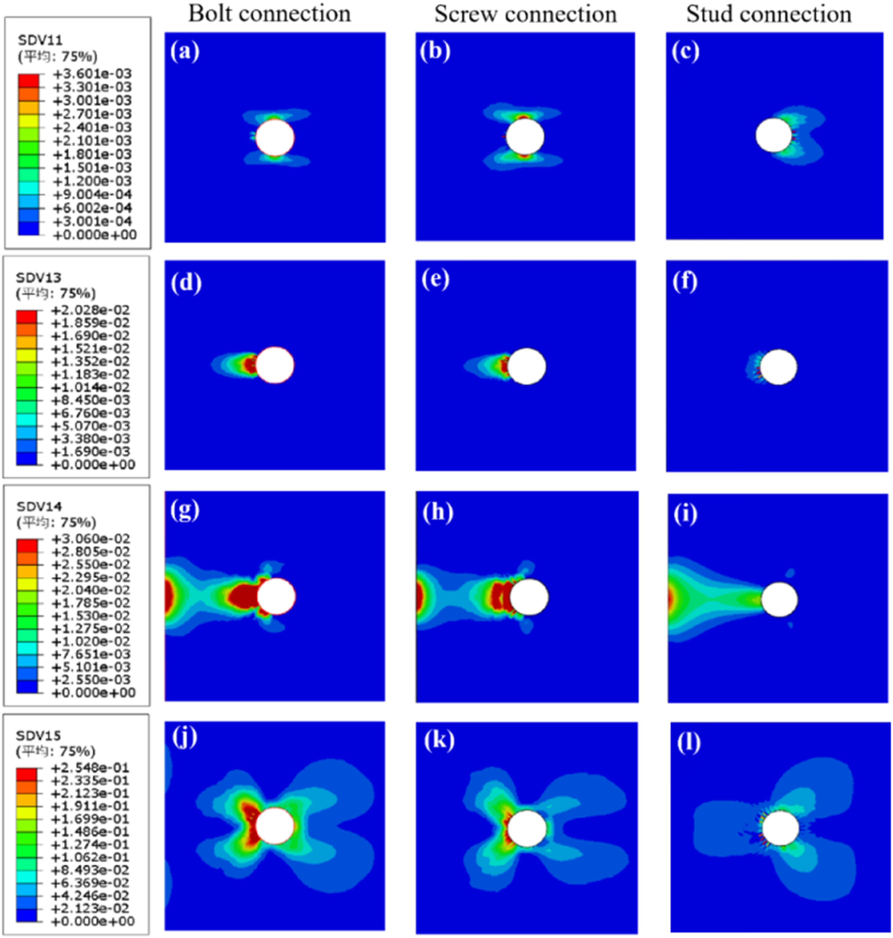
Owing to differences in contact geometry, the stress-concentration patterns vary among specimens. In the structure of bolt connected specimens, assembly clearance exists between the fastener and the hole wall, which causes fastener tilting under loading. This reduces the effective bearing contact area of the hole wall and forces the load to concentrate on the local area around the hole, so the specimen has a larger damage range and more severe damage. For screw connected specimens, the underlying thread engagement, that is, the binding constraint, inhibits the tilting of the screw, resulting in less damage than bolt connected specimens. Stud connection realizes uniform load transfer through full engagement, with a low degree of stress concentration.
The results of peri-hole damage show that the damage of the three types of connected specimens is dominated by matrix failure and supplemented by fiber damage. The root cause of this result is that matrix-related failure is highly concentrated in the bearing area, where transverse compressive stress and shear stress are dominant. This failure pattern occurs because the extrusion and shear resistance of the composite matrix is far lower than that of fibers.
Meanwhile, during the loading process of bolt-connected and screw-connected specimens, fastener tilting and washer extrusion further aggravate the local crushing and shear damage of the matrix around the hole. In this process, the fibers do not bear significant axial loads, so their fracture degree is relatively low.
Figure 9 presents contour plots of the four types of hole-edge damage for the joined components under bolt, screw, and stud connections, all plotted under a unified color scale. This visualization allows for direct observation and comparative analysis of the damage states. To enable a more intuitive comparison of the damage extremes across different connection methods, the maximum values of each damage type are extracted and plotted as bar charts in Figure 10. Specifically, Figure 10(a) illustrates the maximum fiber tensile and fiber compression damage, while Figure 10(b) shows the maximum matrix tensile and matrix compression damage. The numerical values in the charts represent the degree of damage. For example, as clearly shown in Figure 10 for the bolted joint specimen, the matrix compressive damage reaches 0.8371, whereas the fiber compressive damage is only 0.1146. The matrix damage in all three fasteners is orders of magnitude greater than the fiber damage. Hole-edge damage in the tensile plate of the joined component: (a) fiber tension/compression; (b) matrix tension/compression.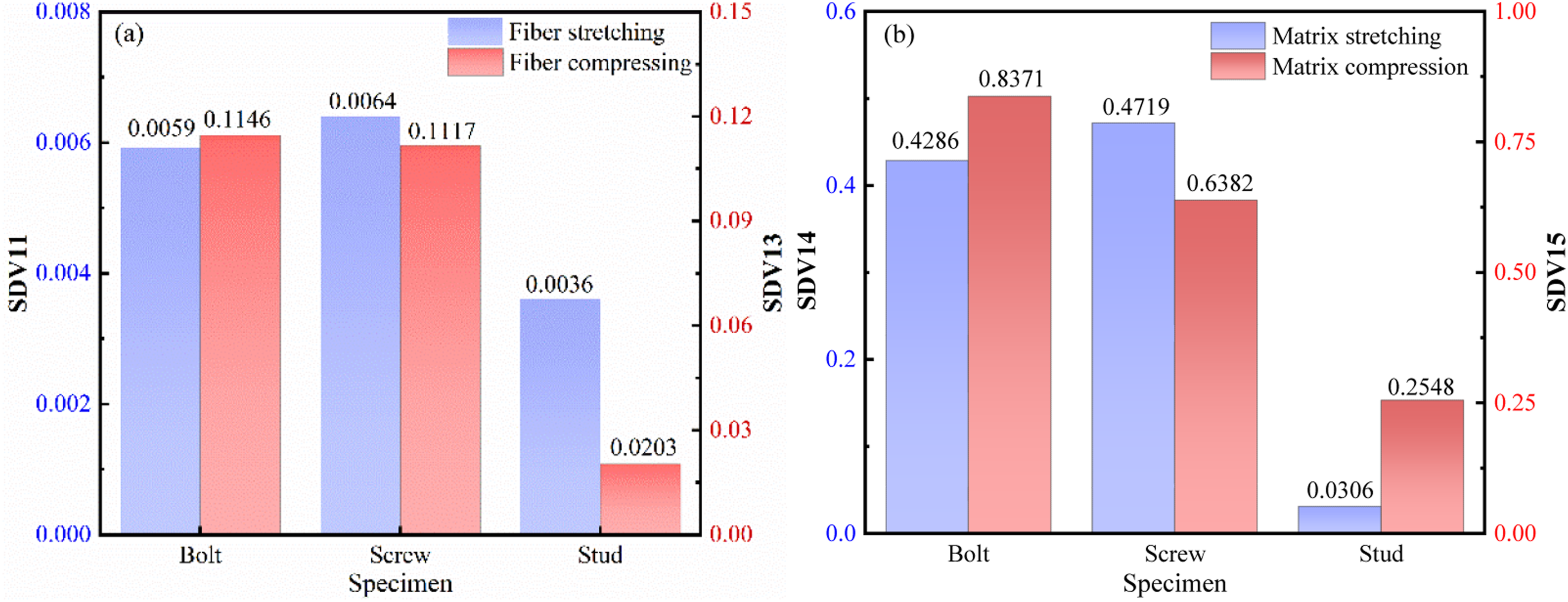
Conclusion
This paper investigated the shear performance and damage progression of GFRP fastened joints using bolt, screw, and stud connections. The simulation results were compared with experimental data, leading to the following conclusions: (1) A progressive damage model was developed based on specimens with different connection methods. The damage analysis of the specimens was conducted using a VUMAT subroutine, which implemented the Hashin failure criterion. The results indicate that the relative errors between the ultimate loads predicted by the simulation model and those obtained from experiments are 3.28%, 3.34%, and 5.49%, respectively. Furthermore, the ranking of the simulated ultimate loads, from highest to lowest, is bolt, screw, and stud connection, which is consistent with the experimental results. This validates the high accuracy and reliability of the model. (2) Numerical simulations and experiments show similar damage outcomes for three types of pure composite material connections. Bolt connections with clearance holes cause severe bolt inclination under load, involving significant tensile and shear stresses during fracture. Screw connections have lower-layer threaded engagement, resulting in slight inclination and combined tensile and shear stresses during fracture. Stud connections feature full threaded engagement, where shear stress predominates over minimal tensile stress during fracture. (3) The numerical simulation results are consistent with the experimental findings. The failure mode observed in both the simulation model and the experiments was fastener fracture. Moreover, the tensile and compressive damage variables for fiber and matrix reveal that matrix damage substantially exceeds fiber damage in all three fastening configurations. Consequently, damage in the joined components is primarily matrix-dominated, with fiber damage accounting for a negligible fraction.。
Footnotes
Funding
The author(s) received no financial support for the research, authorship, and/or publication of this article.
Declaration of conflicting interests
The author(s) declared no potential conflicts of interest with respect to the research, authorship, and/or publication of this article.
Data Availability Statement
The data and materials used during the current study are available from the corresponding author on reasonable request.