






Abstract
Vacuum assisted resin infusion (VARI) molding is an attractive low-cost manufacturing technique for large-scale composite structures. However, its relatively limited curing pressure typically results in inferior manufacturing quality compared with autoclave processing of prepregs. For the VARI process, a series of improvement strategies based on external pressure regulation have been developed, including permanent magnets, external pressure chambers, and inflatable bladders, to improve laminate quality. Despite these efforts, the pressure-dependent evolution of laminate structural quality in composite structures fabricated by vacuum infusion has not been systematically clarified, which limits further process optimization and industrial application. To address this issue, external pressures ranging from 0 to 0.9 MPa were applied during the curing process after resin infusion was completed for composite structures using a vacuum bag and an autoclave. The results showed that appropriate pressure reduces the void content while enhancing laminate compactness and mechanical performance. In contrast, excessive pressure leads to significant resin loss, indicating a competition between void suppression and resin depletion. SEM fractography confirmed that excessive resin loss depletes the interlaminar resin layer, shifting the failure mode from ductile yielding to brittle debonding. Furthermore, a multi-scale coupling mechanism framework was proposed to elucidate the physical origin of this trade-off. Considering these competing effects, an external pressure of approximately 0.3 MPa was identified as providing an optimal balance for manufacturing quality and reliability, offering practical guidance for cost-effective VARI process optimization.
Introduction
Fiber-reinforced polymer (FRP) composites are widely used in the lightweight design of large scale structures due to their high specific strength, high specific stiffness, and excellent design flexibility.1,2 With the increasing demand from composite manufacturers to reduce production costs and shorten manufacturing cycle time, out-of-autoclave processes represented by vacuum assisted resin infusion (VARI) molding are increasingly adopted for the integral manufacturing of large composite structures. 3 In the VARI process, fiber preforms are placed on a single-sided mould and sealed with a flexible vacuum bag. Vacuum pressure is then applied to evacuate air from the mould cavity and to drive resin infiltration into the fiber preform, followed by thermal curing to obtain composite parts. However, due to insufficient curing pressure and incomplete resin infiltration, composite parts manufactured by this method often exhibit low fiber volume fraction, dry spots, and voids defects.4–6
Over the past two decades, researchers have developed a series of improvements to the conventional VARI process. Johnson et al. 7 proposed the use of induction heating during the filling stage to locally reduce resin viscosity, which offsets the effect of non-uniform permeability within the preform layup in the conventional VARI process and eliminates dry spot formation. Rubino and Esperto et al.8,9 developed a microwave heating system for the VARI process, in which the resin was preheated at the inlet by microwave energy to reduce its viscosity. A maximum reduction of 44% in filling time was achieved, and a decrease in void content was observed in the preheated laminate. However, although heating reduces resin viscosity, it also increases the risk of premature gelation. In contrast, Xu et al. 10 applied ultrasonic vibration for 4 minutes during resin infusion, which reduced the apparent viscosity of the epoxy resin from 849.5 MPa·s to 502.9 MPa·s. This treatment improved the dual-scale flow behavior of the resin and effectively suppressed the formation of flow-induced voids. Nevertheless, adverse effects may occur when the ultrasonic energy exceeds a critical threshold. In addition, several improvement strategies have been proposed; however, their practical implementation remains limited due to the difficulty in obtaining auxiliary materials or the complexity of targeted optimization design. For example, Seyhan and Grisin et al.11,12 introduced a semipermeable membrane to separate the vacuum outlet from the surface of the composite part, which permits air and entrapped gases to be extracted from the laminate along the through-thickness direction. This configuration effectively reduces the void content and thickness gradient across the part without compromising compaction. Similarly, Laborderie et al. 13 optimized the perforation spacing of perforated release films positioned above the reinforcement layup during resin infusion to achieve a balance between uniform resin distribution and ease of demolding after curing, while simultaneously reducing intra-tow voids.
In general, recent research on improvement strategies has increasingly focused on pressure regulation in the VARI process, which demonstrates considerable potential for enhancing the manufacturing quality of composite parts. Alms et al. 14 employed a movable external vacuum chamber to locally modify the permeability of the preform, thereby influencing resin flow and improving infusion efficiency and quality. Chen et al. 6 reduced the void content in composite manufacturing by optimizing pressure control at the vent. Full vacuum was applied during the initial stage of infusion to prevent air entrapment, whereas the pressure was moderately increased in the subsequent stage to suppress resin evaporation. In addition, Yalcinkaya et al.15,16 applied moderate external pressure of up to 138 kPa to laminates using an external pressure chamber, which significantly reduced the void content and average void size. Amirkhosravi et al. 17 positioned a set of permanent magnets above the laminate prior to resin infusion, generating an external pressure of approximately 0.3 MPa. Under this condition, the porosity decreased from 6% to below 1% compared with the case without permanent magnets, while the flexural strength increased by more than 11%. Anderson et al. 18 developed a high pressure VARI process in which an inflatable bladder was employed to apply external pressure of up to 483 kPa to the laminate surface. The fabricated laminates exhibited a substantial increase in fiber volume fraction from 42% to 53%, which translated into an approximately 20% improvement in mechanical properties. Nevertheless, despite the encouraging progress achieved in the aforementioned studies, several critical limitations remain in the existing literature. These studies are typically restricted to a relatively narrow pressure range and primarily focus on individual quality indicators, such as voids or flexural strength, without elucidating the trade-offs among multiple parameters. Furthermore, although existing studies have demonstrated that appropriate pressure can reduce void content and enhance laminate compaction and flexural strength,4,19,20,21 such pressure conditions may simultaneously lead to substantial resin depletion within the laminate. Whether higher pressure adversely affects interfacial bonding performance, dimensional accuracy, and other aspects of structural quality therefore remains unclear.
Therefore, FRP laminate samples fabricated using vacuum infusion were manufactured under different levels of external pressure in this study, and their macro and micro scale characteristics, including voids, resin content, thickness, mechanical properties, and fracture surface morphologies, were systematically characterized to clarify the influence of pressure on the manufacturing quality of vacuum infused composite structures. Furthermore, the competing effects between void suppression and resin depletion were evaluated, and a multi-scale coupling mechanism framework was proposed to elucidate the underlying physical interactions governing the pressure-dependent quality evolution. Consequently, an optimal external pressure window of approximately 0.3 MPa was identified to balance void suppression, resin retention, and mechanical performance. A nonlinear fitting approach was also employed to establish a mathematical correlation between curing pressure and void content within the external pressure range of 0–0.9 MPa, thereby providing quantitative guidance for the further optimization and implementation of the VARI process.
Materials and methods
Materials
The reinforcement used for fabricating the composite laminates was unidirectional carbon fiber fabric (SYT49S-12K, 300 g/m2, produced by Zhongfu Shenying Carbon Fiber Co., Ltd.), with a tensile strength of 5500 MPa and a tensile modulus of 250 GPa. The matrix system consisted of an epoxy resin (AF-4303A-2, produced by Wells Advanced Materials Co., Ltd.) and a curing agent (AF-4303B-2, produced by Wells Advanced Materials Co., Ltd.), which were mixed at a weight ratio of 20:17. The mixed resin exhibited a viscosity of approximately 250 MPa·s at room temperature, rendering it suitable for composite fabrication using the VARI process. It should be noted that during the initial curing dwell at 90°C, the resin viscosity decreases significantly to approximately 30 MPa·s, thereby promoting resin flowability and facilitating void expulsion and redistribution under the applied external pressure during the curing stage.
The auxiliary materials required for the VARI process included silicone flow hoses, spiral tubes, T-connectors, flow media, peel-ply, breather fabric, sealant tape, and vacuum bags. All auxiliary materials were capable of withstanding temperatures above 200°C.
Fabrication of FRP parts
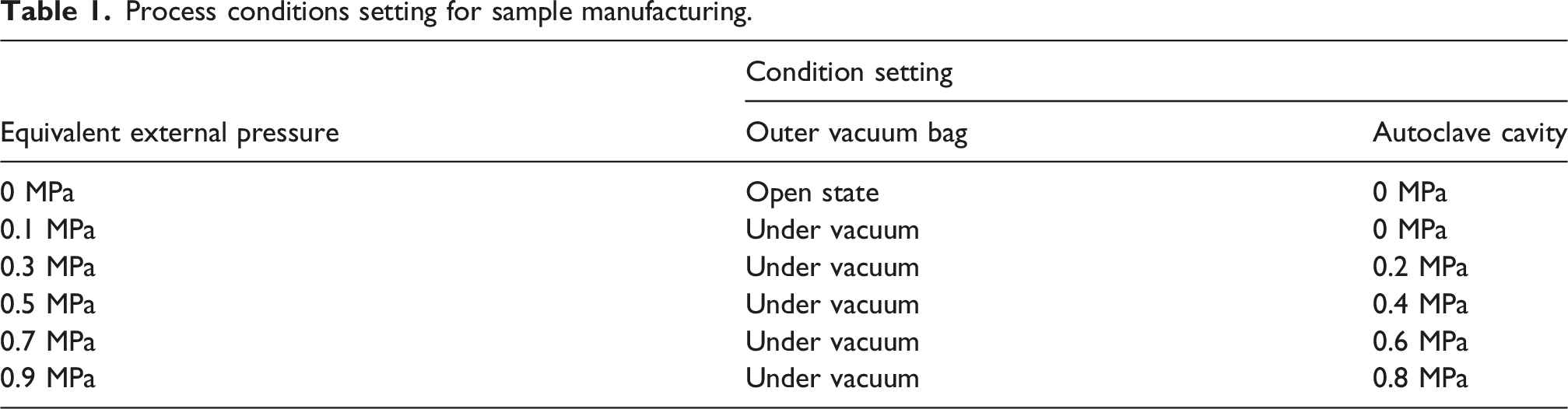
In this study, multiple flat laminate panels with dimensions of 20 cm × 20 cm were fabricated, each consisting of seven plies of unidirectional carbon fiber fabric aligned along the resin flow direction. The fabrication procedure primarily consisted of two key stages: resin infusion and pressurized curing. First, a conventional vacuum infusion process was employed to ensure complete impregnation of the carbon fiber fabric, after which both the inlet and vacuum hoses were sealed. It is emphasized that external pressure was not applied during the infusion stage, and applied only after resin infusion was completed. To prevent air leakage from the flow hoses or vacuum bag under external pressure, samples requiring additional pressurization were enclosed with an extra vacuum bag for secondary sealing. The sealed assemblies were subsequently transferred into an autoclave (model: YT-14-03, supported by Dalian Yingtian Co., Ltd.), where vacuum was continuously maintained throughout the curing process, as illustrated in Figure 1 (a) and (b). According to the curing schedule recommended by the resin manufacturer, a two-stage heating profile was adopted, as shown in Figure 1(c). Experimental procedure of VARI process: (a) schematic representation of encapsulation, (b) photograph of the manufacturing process, (c) manufacturer’s recommended cure cycle.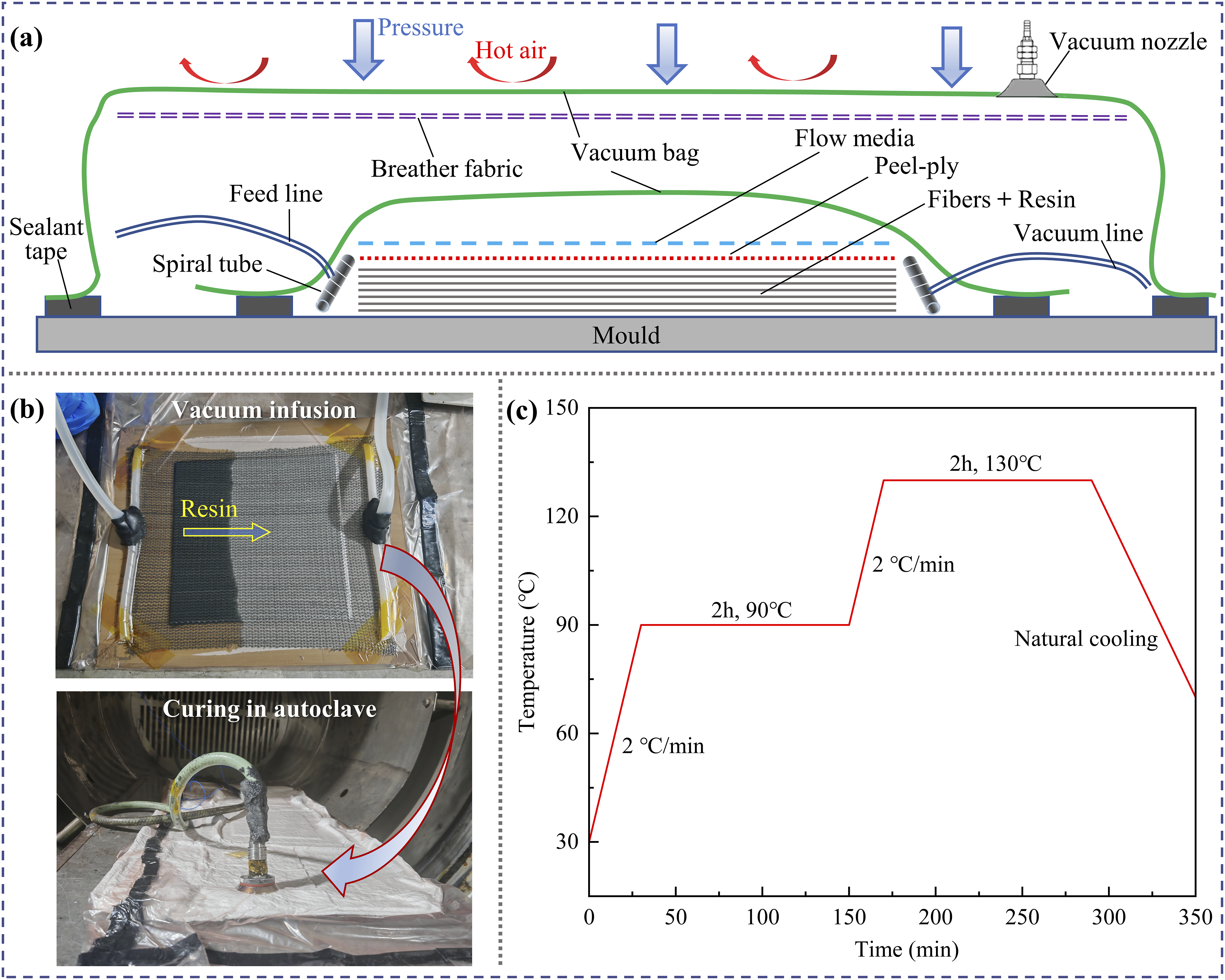
Process conditions setting for sample manufacturing.
Optical digital microscopy analysis
The void content of the composite laminates was determined using an optical microscopy method, which characterizes the microstructural features of voids on two-dimensional cross sections of the samples. Specifically, cross-sectional samples with an area exceeding 50 mm2 were extracted from the central region of the laminate panels. The samples were subsequently embedded in a phenolic resin mounting medium, followed by sequential grinding and polishing to obtain a smooth surface suitable for microscopic observation. The polished surfaces were examined using an optical digital microscope (model: VHX-5000, supported by KEYENCE Co., Ltd.). Image analysis was performed using software (Image Pro Plus 6.0) to evaluate defect morphology. The void fraction was quantified using the area method, defined as the ratio of the total void area to the entire analyzed cross-sectional area in the micrographs.
Resin and fiber content analysis
In this study, the composite laminate panels were fabricated using dry fiber reinforcement and liquid resin. Compared with prepreg-based processes, the resin content cannot be precisely controlled during manufacturing, which may significantly influence the performance of composite structures.
22
Therefore, the resin content of the carbon fiber composites was determined using a loss-on-ignition method. This method calculates the resin fraction based on the mass loss of the sample after high temperature decomposition. Specifically, a single sample weighing approximately 3–5 g was cut from the central region of each laminate panel. After drying, each sample was placed in a stainless-steel tray and weighed using an analytical balance with an accuracy of 1 mg to obtain the initial total mass, denoted as 
Based on the measured resin content, the fiber volume fraction 
Thickness test
The target thickness of the fabricated laminate panels was 2 mm. However, variations in external pressure during curing resulted in noticeable differences in the final cured thickness. To quantitatively evaluate the influence of external pressure on the actual laminate thickness, measurements were conducted using a thickness gauge (accuracy: 0.01 mm, supported by KOSLO Co., Ltd.). For each processing condition, two replicate laminate panels were selected. Three measurement points were randomly chosen within the central region of each panel. The average thickness corresponding to each pressure level was determined as the arithmetic mean of the six measurements obtained from the two panels.
Mechanical properties test
To clarify the influence of external pressure on the mechanical performance of the composite laminates, interlaminar shear strength (ILSS) and transverse tensile strength (TTS) were evaluated using a universal testing machine (model: E45-105, supported by MTS Systems Co., Ltd.).
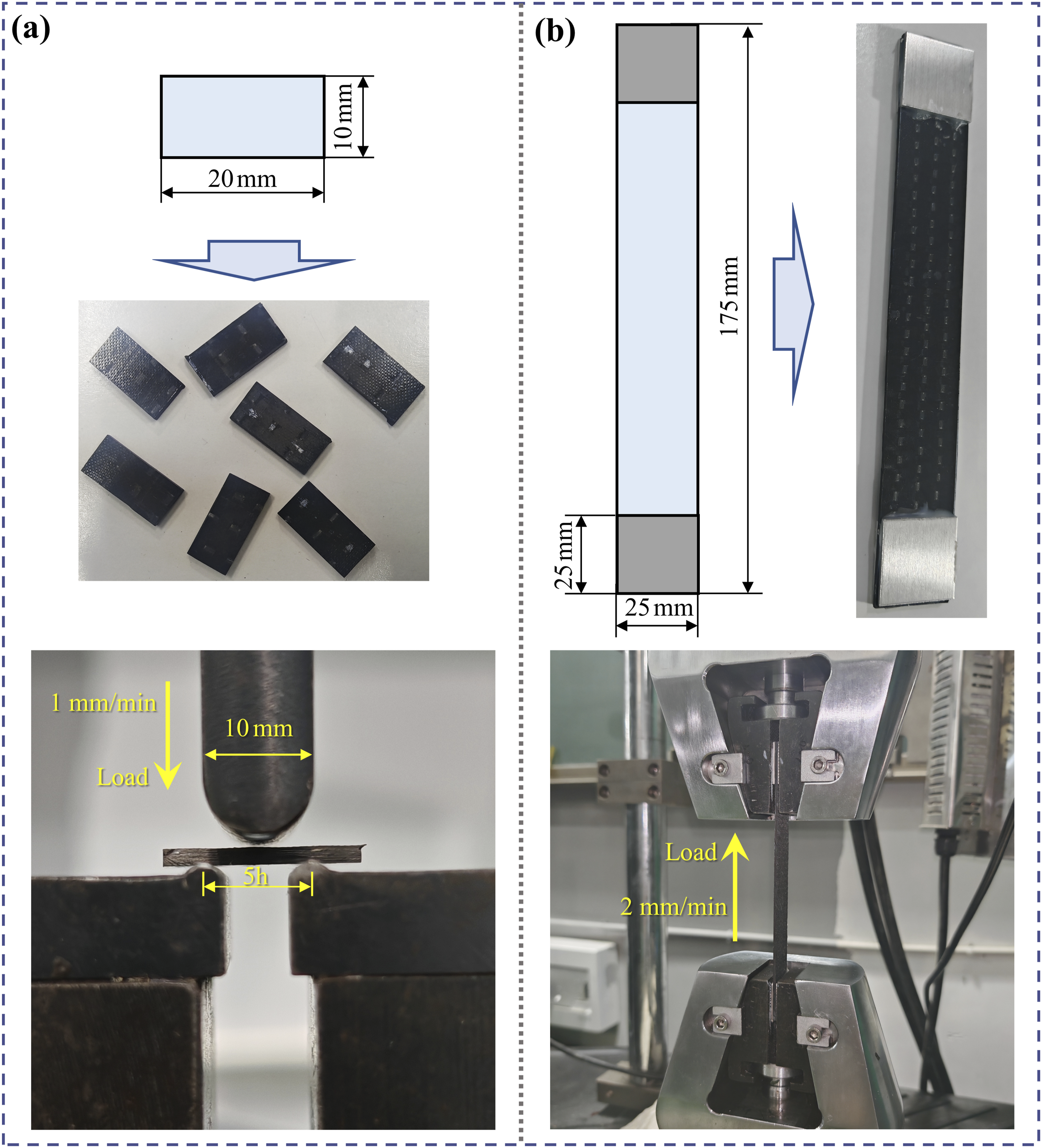
The ILSS was determined using the short-beam method, a sample with a rectangular cross-section is supported as a simply supported beam by two cylindrical supports at the bottom, while a load is applied at the center until failure occurs. The failure mode is dependent on the ratio of the span length between the supports to the thickness of the sample. Sample preparation and testing procedures were conducted in accordance with GB JC/T 773–2010. The group-average span-to-thickness ratio of 5:1 was adopted for all samples, which were cut such that the fiber direction was parallel to the span direction, and the loading rate was 1 mm/min. At least five samples were tested for each processing condition, as illustrated in Figure 2(a). The ILSS was calculated according to equation (3): Mechanical testing methods and sample dimensions: (a) short-beam test, (b) tensile test.
For tensile testing, considering that the maximum longitudinal tensile load of unidirectional laminates is primarily governed by the mechanical properties of the fibers, and given that existing studies have shown that voids mainly affect the transverse tensile strength of unidirectional composites,
23
only the transverse tensile strength was evaluated in this study. Transverse tensile tests were conducted in accordance with the ASTM D3039 standard. Tabs with dimensions of 25 mm × 25 mm × 1.5 mm were adhesively bonded to both ends of the samples. The loading rate was 2 mm/min, and at least five samples were tested for each pressure level, as shown in Figure 2(b). The TTS of the samples was calculated as:
Fracture surface analysis
To elucidate the fracture mechanisms and resin loss characteristics, specimens cured under two external pressure conditions (0 MPa and 0.9 MPa) were selected, and the fracture surfaces of representative short-beam shear and transverse tensile samples were examined using a scanning electron microscope (SEM, model: Regulus 8230, supported by Hitachi Co., Ltd.). After mechanical testing, debris on the fractured sample surfaces was removed using an air blower. Subsequently, the samples were sputter-coated with a thin layer of gold to enhance electrical conductivity. SEM observations were conducted at an accelerating voltage of 5.0 kV and a working distance of 8–10 mm, focusing on resin distribution, fiber fracture, interfacial resin layer thickness, and debonding features on the sample surfaces.
Results and discussion
Resin content and fiber volume fraction
During the curing process of vacuum infused composites, external pressure serves as a critical process parameter that directly governs the compaction behavior of the fiber preform and the flow behavior of the resin matrix. Figure 3 shows the variation in resin content and fiber volume fraction of the 49S/4303 laminates fabricated under different external pressures. The results indicate that compared with the samples cured at 0 MPa, the resin content of the samples decreased by 53.6% and the fiber volume fraction increased by 79.8% after the application of 0.1 MPa external pressure. This pronounced change suggests that even a relatively low external pressure effectively promotes resin expulsion and enhances densification of the fiber network. As the external pressure was further increased from 0.1 MPa to 0.9 MPa, the relative proportions of fiber and resin gradually stabilized. Within this pressure range, the resin content decreased by a maximum of 11.1%, while the fiber volume fraction increased by up to 4.9%, indicating that the compositional parameters became less sensitive to additional pressure increments. Material composition of 49S/4303 laminates fabricated under different external pressures: (a) resin content, (b) fiber volume fraction.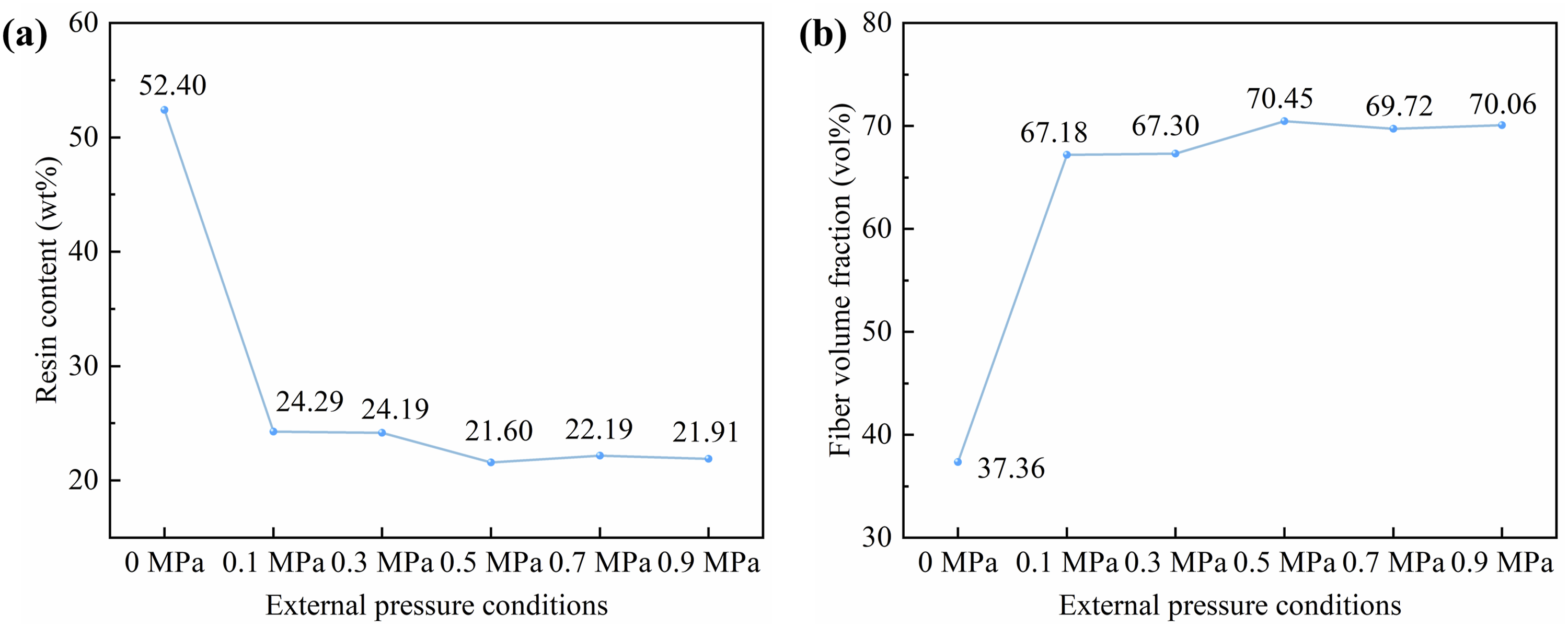
Voids
Figure 4 shows the surface morphologies of the 49S/4303 composite laminates cured under external pressures ranging from 0 to 0.9 MPa. Under the condition without additional external pressure (0 MPa), large-sized voids are clearly observed within the laminate, and there are serious resin-rich phenomena between the fiber bundles, which will adversely affect the overall compactness and structural integrity of composite laminates. After external pressure is applied, the formation of voids will be effectively suppressed. However, it is worth noting that the unidirectional carbon fiber fabric requires thermoplastic binder yarns in the weft direction for weaving, and the few voids remaining in the pressurized samples are mainly concentrated in these regions. Surface morphologies of 49S/4303 laminates fabricated under different external pressures: (a) 0 MPa, (b) 0.1 MPa, (c) 0.3 MPa, (d) 0.5 MPa, (e) 0.7 MPa, (f) 0.9 MPa.
Further void analysis revealed that when an external pressure above 0.1 MPa was applied during curing of the 49S/4303 composite laminates, the void content decreased significantly to below 0.5%, as shown in Figure 5(a). When the external pressure reaches 0.1 MPa, the void content decreases gradually with further pressure increase and eventually stabilizes at an extremely low level of approximately 0.1%. This evolution behavior reflects the underlying physical mechanisms governing void development during pressurized curing of vacuum infused laminates. Under low-pressure conditions (≤ 0.1 MPa), the applied pressure primarily overcomes the elastic resistance of the fiber preform, resulting in significant compaction. The additional driving force also promotes resin infiltration and facilitates the expulsion of macro-voids entrapped within the preform architecture. As the pressure increases into the intermediate and high ranges (> 0.1 MPa), the preform approaches a densely compacted state. The remaining defects predominantly consist of micro-voids located around thermoplastic binder yarns, within fiber tows, or at the fiber–resin interface. At this pressure, the rate of void reduction decreases markedly because eliminating these micro-scale defects requires substantially higher pressure to overcome the increased flow resistance of the resin within narrow capillary channels. In addition, interfacial interactions and the intrinsic rheological characteristics of the resin may further limit defect removal efficiency. Previous studies have also reported that excessively high fiber volume fractions may impair resin impregnation and even increase void content.
24
Therefore, optimization of the vacuum infusion process should avoid the application of excessively high external pressure, as excessive resin loss may lead to deterioration of interfacial bonding and overall structural performance. Void content of 49S/4303 laminates fabricated under different external pressures: (a) variation curve, (b) curve fitting.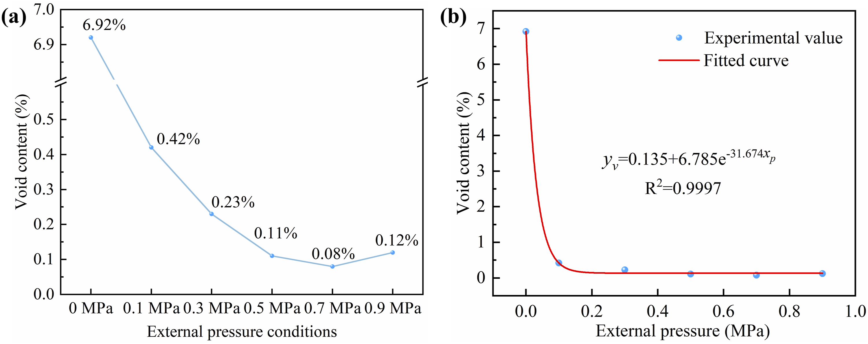
In addition, to provide quantitative guidance for the optimization of pressure-assisted VARI processes, a curve fitting analysis was performed to establish the correlation between void content and external pressure. As shown in Figure 5(b), the void content of the laminates exhibits a sharp decrease followed by gradual stabilization as the external pressure increases from 0 to 0.9 MPa. Considering both physical interpretability and goodness of fit, an exponential decay model was selected to describe the observed trend, as it effectively captures the rapid attenuation behavior at low pressure and the asymptotic stabilization at higher pressure levels. The nonlinear regression produced a smooth fitting curve with a high coefficient of determination (R2 = 0.9997), indicating excellent agreement with the experimental data. The relationship can be expressed as equation (5):
The exponential decay model captures the two-stage void expulsion behavior observed experimentally: (i) rapid attenuation at low pressure (0–0.1 MPa), where macro-voids are efficiently expelled as the external pressure overcomes the elastic resistance of the fiber preform; and (ii) asymptotic stabilization at higher pressure (>0.1 MPa), where only micro-voids remain trapped within fiber tows and around thermoplastic binder yarns (Figure 4), which are difficult to eliminate due to increased flow resistance in narrow capillary channels. The fitted parameters are physically interpretable: the constant term 0.135 represents the residual micro-void fraction, 6.785 the initial eliminable void content, and 31.674 a characteristic pressure parameter. This curve quantitatively characterizes the void suppression trend within the tested 0–0.9 MPa range to support the optimal pressure window identification, rather than serving as a rigorous predictive tool for extrapolation.
Thickness
Figure 6 shows the average thickness changes of composite laminates fabricated under different external pressures, which directly confirms the positive effect of external pressure on curing compactness. Compared to samples fabricated without applied pressure, the average thickness of the laminates decreased sharply from 2.97 mm to 1.82 mm upon the application of an external pressure of 0.1 MPa, representing a reduction of 38.7%. This significant thickness reduction is primarily attributed to the external pressure overcoming the inherent stiffness of the fiber preform, inducing macroscopic elastic deformation of the fiber network and facilitating the rapid expulsion of interlaminar voids and air bubbles. This phenomenon corresponds precisely to the densification revealed by the preceding compositional analysis, which showed a sharp decrease in resin content and a corresponding increase in fiber volume fraction. When the external pressure was further increased from 0.1 MPa to 0.9 MPa, the average thickness of the laminates decreased only slightly from 1.82 mm to 1.66 mm, representing a total reduction of just 8.8%, and the average thickness of the laminate tended to be stable. This phenomenon indicates that the fiber network had already reached a near-limit compaction state under external pressure, and the adjacent fibers were in close contact and formed a stable load-bearing skeleton. Consequently, the additional applied pressure was predominantly resisted by the already densely compacted fiber framework, resulting in only a negligible additional reduction in macroscopic thickness. The thickness “plateau region” is consistent with the stabilized trends observed for resin content and fiber volume fraction at higher pressure levels. Together, these results indicate that once the applied pressure exceeds a critical value of approximately 0.5 MPa, further increases external pressure no significant changes in laminate thickness or compaction. Pursuing pressures beyond 0.5 MPa offers limited benefits for controlling final part dimensions (thickness), as the laminate has already entered the compaction plateau region. Therefore, in practical process design, a “stepped pressurization” strategy can be considered: an initial rapid pressure application to approximately 0.5 MPa ensures adequate compaction, followed by a relatively economical holding pressure during curing, provided that other performance requirements (e.g., resin infiltration) are satisfied. This approach achieves a balance between processing efficiency and part performance. Thickness variation of 49S/4303 laminates fabricated under different external pressures.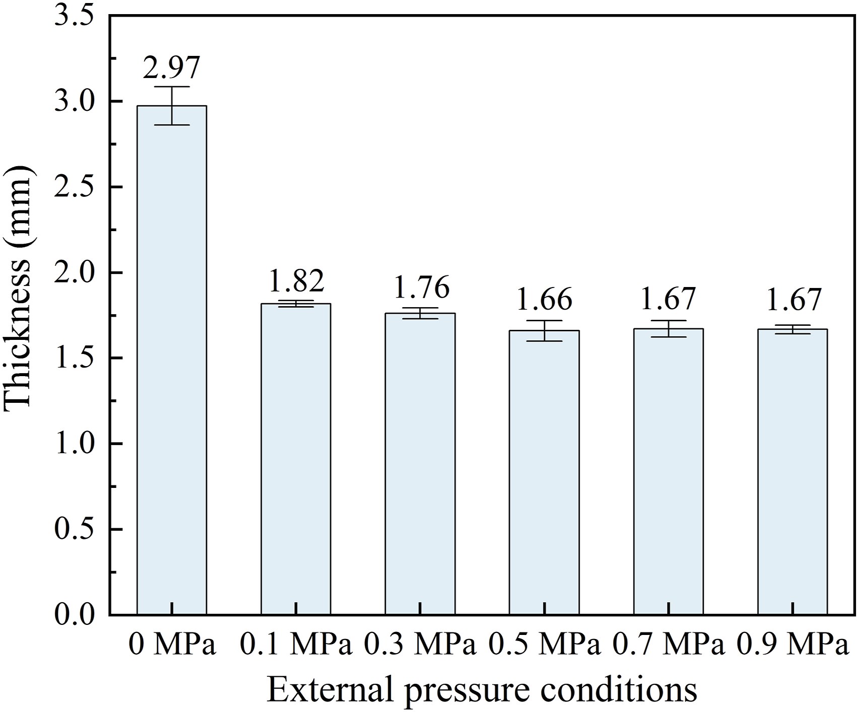
Interlaminar shear strength (ILSS)
Figure 7 shows the short-beam test results of the 49S/4303 laminates fabricated under different external pressures. The results reveal a key phenomenon contrary to conventional expectations: the samples prepared without applied external pressure exhibited the highest maximum load and ILSS (63.8 MPa), whereas the ILSS decreased systematically with increasing external pressure. This overall decreasing trend is highly consistent with the reduction in resin content shown in Figure 3, and can be primarily attributed to the role of the resin matrix in interfacial stress transfer. Under a curing pressure of 0 MPa, the laminate contains a relatively high resin fraction and abundant resin-rich regions, which enable the formation of a moderately thick, continuous, and uniform resin matrix layer at both the fiber–resin interface and the interlaminar regions. This resin layer acts as an effective stress transfer medium: under shear loading, it undergoes plastic deformation, facilitating efficient stress transfer from the matrix to the fibers, while simultaneously blunting surface micro defects on the fibers and mitigating stress concentration, thereby significantly enhancing the interfacial bonding performance of the laminate. Short-beam test results of 49S/4303 laminate samples fabricated under different external pressures: (a) representative load–displacement curves, (b) ILSS.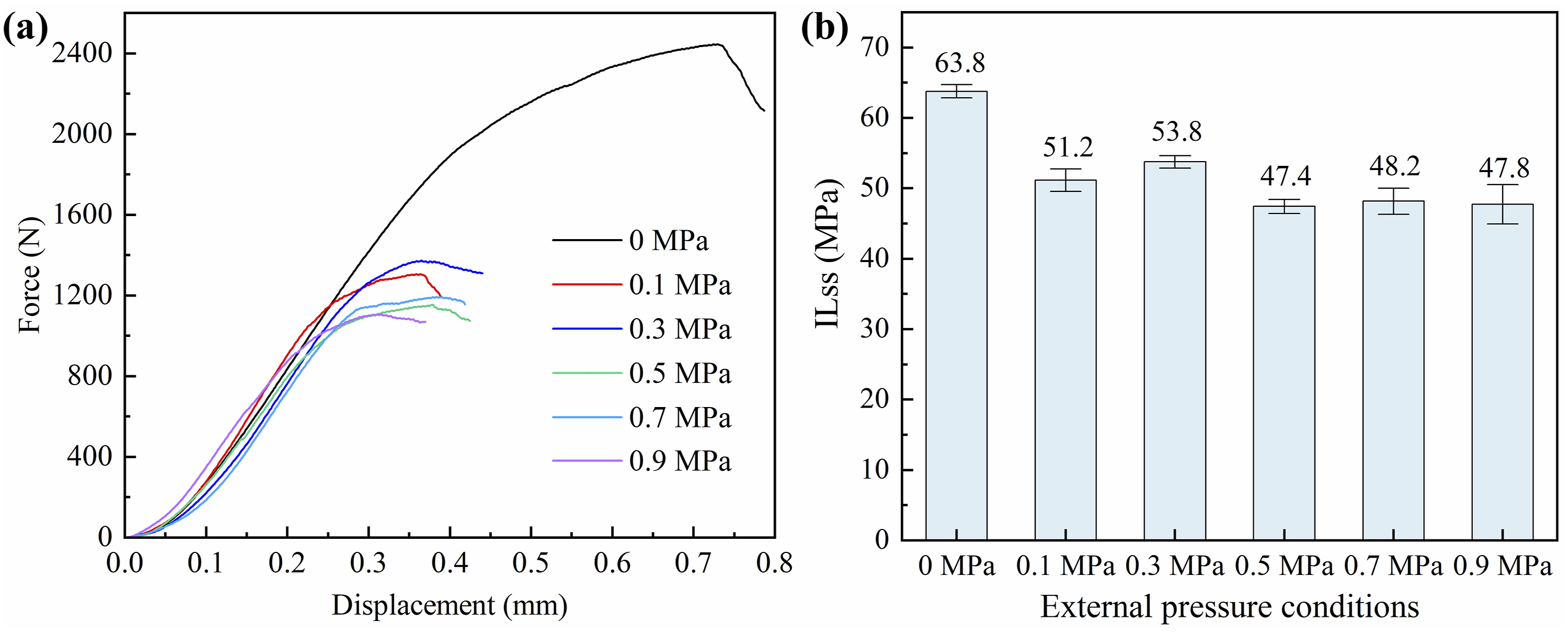
However, once external pressure (e.g., 0.1 MPa and above) is applied, the situation changes fundamentally. While the external pressure markedly compresses the fiber preform, increases the fiber volume fraction, and reduces void content, it also induces substantial resin loss (from 52.4 wt% at 0 MPa to approximately 22 wt% at 0.1 MPa and above, as shown in Figure 3(a)). This severe resin depletion leads to thinning of the interlaminar resin layer, thereby exerting a detrimental effect on the ILSS. Related studies 25 have likewise reported that the ILSS of composites decreases with increasing fiber content, which further corroborates the above discussion. Therefore, considering the combined influence of void content variations under different external pressures, the ILSS of the laminate samples in Figure 7(b) exhibits an initial sharp decline, followed by a slight recovery, and finally a gradual decrease to a stable plateau with increasing pressure.
Transverse tensile strength(TTS)
Figure 8 shows the transverse tensile test results of 49S/4303 laminate samples fabricated under different external pressures. It can be observed that although the laminate sample cured at 0 MPa exhibits the highest failure load, its calculated tensile strength remains relatively low because its actual cross-sectional thickness is significantly greater than that of the other samples. In contrast, when the external pressure was controlled within 0.3–0.5 MPa, the composite laminates achieved relatively high TTS, representing an improvement of more than 26% compared with samples cured without applied pressure. Both excessively low and excessively high external pressures during laminate curing adversely affect the TTS. This variation trend is similar to that observed for ILSS and is evidently governed by the combined effects of void and resin content under different external pressures. The TTS reaches relatively high values within the 0.3–0.5 MPa range, peaking at 36.11 MPa under 0.5 MPa and achieving 34.99 MPa at 0.3 MPa, which represents an improvement of more than 26% compared with samples cured without applied pressure. This non-monotonic dependence reflects the competing influence of void suppression and resin retention on transverse load-bearing behavior, and the underlying trade-off will be systematically discussed in Section 3.7. Tensile test results of 49S/4303 laminate samples fabricated under different external pressures: (a) representative load–displacement curves, (b) TTS.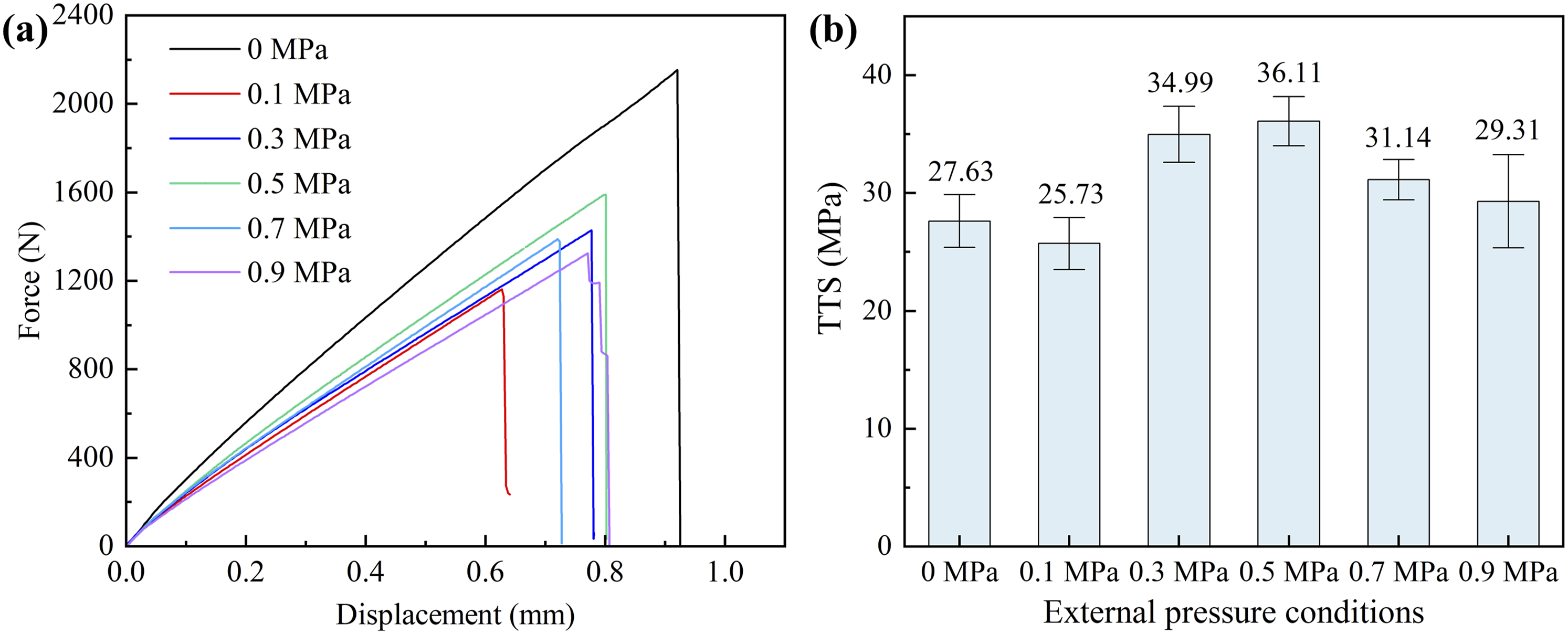
Fracture surface morphologies
Figure 9 shows the fracture surface morphologies of laminates cured at 0 MPa and 0.9 MPa under interlaminar shear and transverse tensile failure modes, revealing the pronounced influence of external pressure on resin distribution and interfacial load-bearing behavior. Under interlaminar shear failure (Figure 9a and b)), the 0 MPa samples exhibit distinct ductile fracture characteristics, with a relatively thick and continuous interlaminar resin layer. The rough fracture surface and evident plastic deformation features indicate that the resin matrix undergoes plastic flow during shear loading, effectively transferring stress and blunting crack tips. This observation is consistent with the relatively high resin content (52.40 wt%) and the highest measured ILSS (63.8 MPa) of this group. In contrast, the shear fracture surfaces of the 0.9 MPa samples show substantial depletion of the interfacial resin layer, reduced spacing between fiber tows, and extensive fiber exposure and fracture. Excessive resin loss (resin content reduced to 21.91 wt%) nearly eliminates the interlaminar load transfer medium, shifting the failure mechanism from matrix-dominated ductile yielding to brittle failure governed by interfacial debonding and fiber sliding, which directly leads to a reduction in ILSS to 47.8 MPa. The transverse tensile fracture morphologies (Figure 9c and d)) further corroborate these observations. For the 0 MPa samples, abundant resin residues are observed adhering to the fiber surfaces, and even fractured fiber bundles are not directly exposed, indicating strong interfacial anchoring. However, the relatively high porosity (6.92%) reduces the effective load-bearing area, and stress concentration at pore edges is likely to promote premature crack initiation, thereby limiting the improvement of TTS (27.63 MPa). For the 0.9 MPa samples, only a small amount of resin remains attached to the fiber surfaces, and the fractured fibers are almost completely exposed. Cracks propagate rapidly along the weakened fiber/resin interface, exhibiting typical low-energy brittle fracture characteristics. Although high pressure effectively suppresses void defects, excessive resin depletion (21.91 wt%) severely weakens interfacial bonding strength, causing TTS to decrease from its peak value at the optimal pressure (36.11 MPa) to 29.31 MPa. SEM fracture morphologies of 49S/4303 laminates after mechanical testing: (a) 0 MPa, interlaminar shear, (b) 0.9 MPa, interlaminar shear, (c) 0 MPa, transverse tension, (d) 0.9 MPa, transverse tension.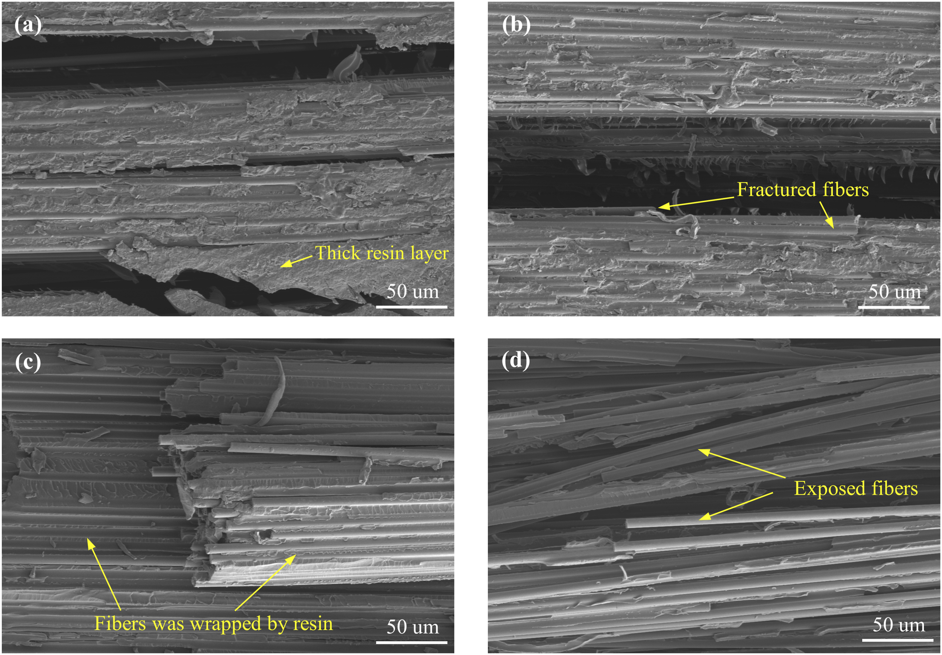
Competing effects
The preceding sections systematically characterized the influence of external pressure on resin content, void content, thickness, and mechanical properties (Sections 3.1–3.6). The results indicate that these parameters do not evolve monotonically with external pressure, but are rather governed by the coupled regulation of multiple physical mechanisms during curing. To intuitively illustrate the competing trends of key quality parameters under external curing pressure, the actual values of multiple parameters were normalized to a unified scale to facilitate comparative evaluation in a single diagram. Following equation (6), the maximum value of each parameter within the 0–0.9 MPa range was mapped to 1 and the minimum to 0, and the curves were replotted as shown in Figure 10. Normalized competing trends of key quality parameters with external pressure.
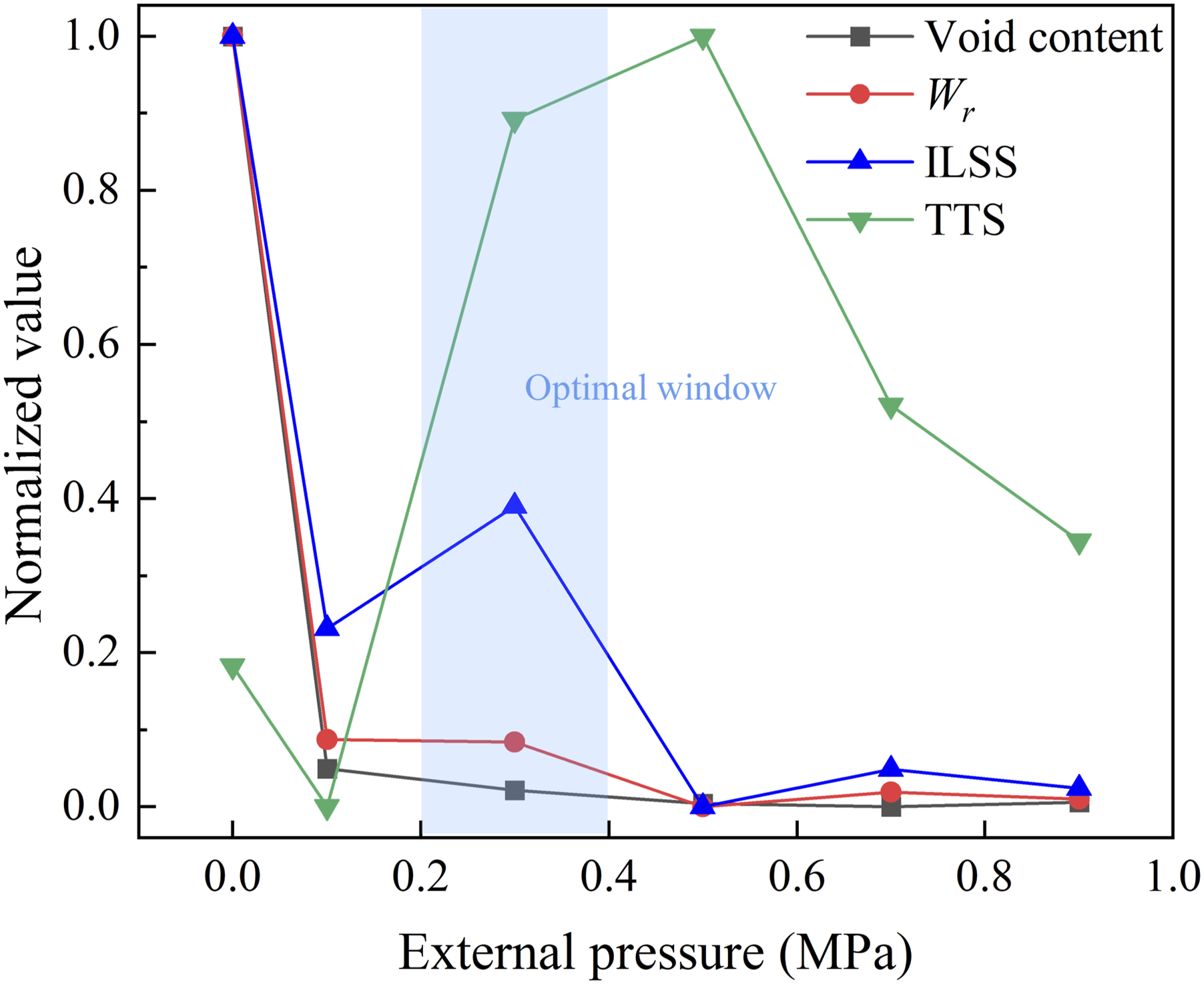
The normalized competing curves in Figure 10 further quantify this trade-off: in the 0–0.1 MPa interval, the void content decreases sharply while the resin content has already undergone substantial loss. In the 0.3–0.5 MPa interval, the void content is reduced to 0.1–0.23%, and the resin content remains at a level sufficient to sustain interfacial bonding; within this range, both ILSS and TTS reach their peak values. Beyond 0.5 MPa, resin bleeding leads to critical depletion of the interfacial resin layer, and both ILSS and TTS deteriorate. Only at approximately 0.3 MPa is the benefit of “void suppression” maximized while the cost of “resin bleeding” remains insignificant, thereby forming a non-monotonic optimal window.
The competing and coupled relationships among the aforementioned mechanisms are summarized in the framework shown in Figure 11. Specifically: Coupling mechanism framework of external pressure effects on composites quality.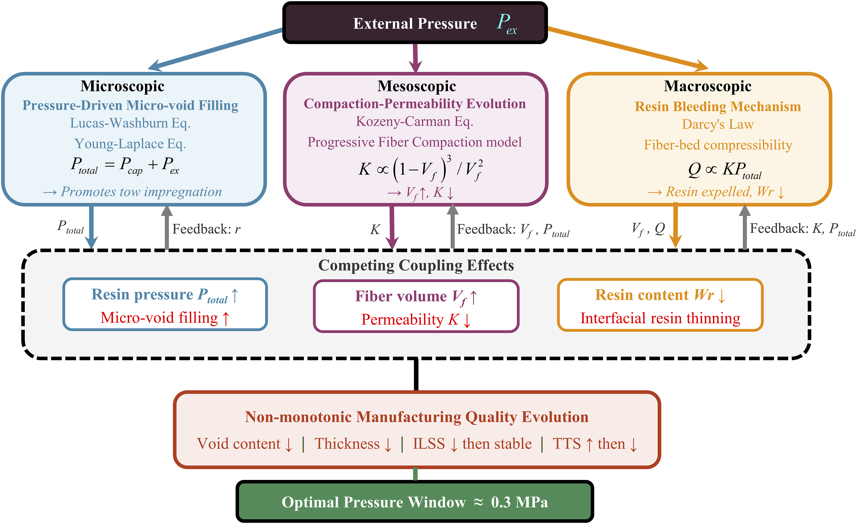
For the microscopic scale, external pressure reinforces the driving force for resin impregnation into fiber tows by superimposing onto the capillary pressure. The infiltration of resin into fiber tows follows the Lucas-Washburn equation:

The external pressure 
For the mesoscopic scale, the permeability of composites under different external pressures usually varies significantly. The permeability after compaction can be described by the Kozeny-Carman relation
26
:
Furthermore, according to the “progressive” fiber compaction model proposed by Dave
28
and Gutowski,
26
the external load is primarily borne by the resin layer in the initial stage of curing. As curing proceeds, the fiber preform is gradually compacted, the fiber volume fraction increases, and the external load is progressively transferred to the fibers. The relationship between fiber volume fraction and pressure during composites curing can be expressed by the following equations:


For the macroscopic scale, the total fluid volume passing through a cross-section of the porous medium per unit time can be obtained by combining Darcy’s law:
By integrating the aforementioned theoretical formulations with the preceding experimental results, it is evident that the resin flow capability during specimen curing does not exhibit monotonic behavior, but is instead governed by the coupled influence of permeability and resin pressure. Under insufficient pressure, the driving force for resin infiltration is inadequate, compromising impregnation uniformity. Conversely, under extreme pressure conditions beyond the tested range, severely reduced permeability could theoretically hinder resin redistribution and create conditions conducive to void formation or dry spots. Under these physical constraints, increasing the external pressure during curing leads to a decrease in overall resin content, an increase in fiber volume fraction, and reductions in both void content and thickness, while the mechanical properties exhibit a non-monotonic evolution trend. These three scales are inherently coupled through the mutual dependence of external pressure, fiber volume fraction, permeability, and void content during curing. Specifically, the microscopic infiltration driving force (equation (9)) governs tow-scale impregnation, which influences the mesoscopic permeability (equation (10)) and compaction state (equations (11)–(13)), and these in turn determine the macroscopic resin flow behavior (equation (14)) that ultimately governs void evolution and resin retention.
Conclusions
This study investigated composite laminates cured under external pressures ranging from 0 to 0.9 MPa applied after resin infusion was completed. Through microstructural characterization, mechanical testing, and fractographic analysis, the effects of external pressure on resin content, voids, thickness, ILSS, and TTS were systematically analyzed. Additionally, a multi-scale coupling mechanism framework was proposed, integrating the Lucas–Washburn infiltration model, Kozeny–Carman permeability relation, progressive fiber compaction theory, and Darcy’s law, to clarify the coupled regulation of resin flow, compaction behavior, and void evolution during pressurized curing. The regulatory mechanism of external pressure on the performance of vacuum infused composite structures was clarified, providing guidance for subsequent optimization of the VARI process.
The results indicate that when the external pressure reaches 0.1 MPa, the void content decreases significantly to below 0.5%, while the resin content is reduced to approximately 22 wt% and gradually stabilizes, leading to effective densification of the fiber skeleton. The variation of void content with pressure follows an exponential decay model (R2 = 0.9997). Within the pressure range of 0.3–0.5 MPa, the composites exhibit superior TTS, showing an improvement of more than 26% compared with samples cured without applied pressure. However, the ILSS decreases systematically after pressurization, which is attributed to resin loss and the resulting depletion of the interlaminar resin layer. SEM fracture surface analysis revealed that samples cured without external pressure exhibit distinct ductile fracture characteristics with a relatively thick and continuous interlaminar resin layer, whereas excessive pressure causes severe resin depletion and brittle failure governed by interfacial debonding and fiber sliding. Normalized competing curves further quantified this trade-off, confirming that approximately 0.3 MPa represents the optimal pressure window where the benefit of void suppression is maximized while the cost of resin bleeding remains insignificant, thereby achieving a balanced combination of compaction, thickness control, and mechanical properties.
Footnotes
Acknowledgement
The authors gratefully acknowledge Zoomlion Heavy Industry Science&Technology Co., Ltd. for their support in experimental materials.

Funding
The authors disclosed receipt of the following financial support for the research, authorship, and/or publication of this article: This paper was supported by the National Key Research and Development Program of China (No. 2024YFB3411102), the National Natural Science Foundation of China (No. 52175373), and the Science and Technology Innovation Program of Hunan Province (No. 2025JK2052).
Declaration of conflicting interests
The authors declared no potential conflicts of interest with respect to the research, authorship, and/or publication of this article.
Data Availability Statement
Data sharing not applicable to this article as no datasets were generated or analyzed during the current study.