
Abstract
To determine the causes of failure of an artificial temporomandibular joint implant, one must study the magnitude and location of the maximum stresses under physiological loading. In this study, we analyzed the stresses in a commercially available TMJ implant, the bone (i.e., mandible), and the bone-implant interface using a finite element software package. Both titanium and Co-Cr-Mo/Vitallium metals as well as bones with various degrees of osteoporosis were studied. The results of the analysis showed that the maximum stresses occurred at the location of the first screw hole (closest to the condyle) of the implant. In addition, the highest microstrains were observed in the bone adjacent to the first screw hole. The results of our study have potential clinical benefit in terms of improved implant design and hence better performance.
INTRODUCTION
The temporomandibular joint (TMJ) is a bilateral joint of the jaw that functions as a single entity during normal masticatory activities, speaking, yawning, and swallowing. Approximately 10 million Americans suffer from temporomandibular disorders or TMDs (Temporomandibular Joint and Muscle Disorders, http://www.nidcr.nih.gov/OralHealth/Topics/TMJ/, accessed October 14, 2009). Although most individuals with TMDs are treated conservatively, true joint pathology of the TMJ sometimes warrants an artificial joint replacement. TMJ replacement has been indicated in cases of joint trauma, advanced degenerative disease, tumors, developmental anomalies, and ankylosis of the joint following injury (Christensen, 1964; Saeed et al., 2002; Dimitroulis, 2005; Driemel et al., 2009). The field of alloplastic TMJ replacement is still evolving, and further research is needed to characterize the essential design features and biomechanical requirements of these prostheses.
There is no universally accepted implant for replacement of the TMJ (Driemel et al., 2009). Alloplastic replacement of the TMJ generally involves the use of a condylar implant with an articulating glenoid fossa component (Fig. 1a). In some clinical situations, only the glenoid fossa is replaced, leaving the condylar portion intact. The TMJ is a joint that is subjected to functional loads during physiological movements (Tanaka and Koolstra, 2008). Finite element analysis (FEA) is a useful tool that can be applied to quantify the stress distribution in the implant and surrounding tissues, and it has been used previously for study of the biomechanical behavior of orthopedic devices, including hip, knee, and spinal implants, under various loading conditions (Crowninshield et al., 1983; Keyak and Falkinstein, 2003; Majumder et al., 2005; Morra and Greenwald, 2005; Goel et al., 2006; Poggie et al., 2007).
Several authors have developed finite element (FE) models for the TMJ, including the articular cartilage. However, few studies have used mathematical or FE analysis to investigate TMJ implants (Chen et al., 1998; Beek et al., 2001; DeVocht et al., 2001; May et al., 2001; Tanaka et al., 2001; Donzelli et al., 2004; Tanaka et al., 2004; Pérez del Palomar and Doblare, 2006). To determine the causes of failure of an artificial TMJ implant, one must study the magnitude and location of the maximum stresses under physiological loading. Therefore, the goals of this study were to quantify the stress distribution in the Christensen implant, bone, and implant-bone interface, and to compare the stresses and strains with those in different bone conditions and implant materials.
MATERIALS & METHODS
The geometry of the TMJ, including the material properties of cancellous and cortical bone, was obtained from CT images [110 kVp 105 mAs, 5-mm-thick slices at 2.5-mm intervals, 96 slices, acquisition matrix 512x512, field of view 378x378 mm, in plane resolution 0.738 x 0.738 mm (pixel size); Siemens, Bensheim, Germany]. Because the CT data were obtained from an individual without any identifying information, the process was considered exempt by the IRB. We used these data in MIMICS, an image-processing software, to form the geometry of the jaw before it could be introduced into ANSYS, a FE software. In addition, a model of the TMJ implant was developed and introduced into the finite element mandible model by a subtraction method to simulate the post-surgical condition (Fig. 1b). A TMJ implant with a maximum of 10 screws was utilized for the study (Fig. 1c). The nodes and elements were generated in the mandible and implant volume. Contact elements were used to model the interface between the implant and bone. We introduced all the elements of bone to MIMICS again to assign the elements by element material property proportionate with its average magnitude of grey values of all pixels within that element. The details of this derivation have been described by us and others previously and will not be repeated here (Keyak and Falkinstein, 2003; Majumder et al., 2007, 2008).
The density and Young’s modulus were calculated according to the pixel value in Hounsfield units (HU). Two hundred different values of Young’s modulus, interpolated from the highest and lowest values of the calculated modulus, were considered for modeling of the material properties of the mandible. For each finite element, MIMICS software assigned one of these 200 values according to the element’s average pixel value, which was given in HU. By this technique, the heterogeneity of bone was modeled for FEA. In the same mandible model, we simulated 4 different types of bone qualities by changing the coefficient of HU. We repeated the simulation 4 times to model 4 different types of bone (ranging from osteoporotic to normal/healthy bone). This was done to delineate the variations in stress distribution for the different bone conditions following implantation.
Type I bone simulated osteoporotic bone, whereas Type IV bone simulated bone that was similar to that in a healthy adult. The range of the Young’s modulus for Type I, Type II, Type III, and Type IV bone varied from 31 to 811 MPa, 46 to 917 MPa, 54 to 1006 MPa, and 66 to 1092 MPa, respectively. The Young’s modulus values for the different cancellous bone types were obtained from the literature (Keyak and Falkinstein, 2003; Majumder et al., 2005). The elements with the assigned properties were transferred to ANSYS. The total number of elements and nodes generated in the FE model were 78,244 and 122,833 for the combined mandible and the TMJ implant model, respectively. The shape of the element was tetrahedral with 10 nodes, i.e., each side had a mid-side node, and each node had 3 degrees of freedom. In this study, the Young’s modulus values that were used for titanium and Co-Cr-Mo alloys were 117 GPa and 230 GPa, respectively. The Poisson’s ratio was assumed to be 0.3 for both materials.
Muscle and Joint Forces
The muscles of mastication have significant influence on the TMJ complex and transmit functional chewing forces to them. Among the 4 muscles of mastication, 3 (i.e., masseter, medial pterygoid, and temporalis) are activated to close the mouth, and 1 (i.e., lateral pterygoid) is used for mouth opening. We considered the 3 muscles that are involved in mouth closing, since these movements would result in physiological loading at the TMJ complex. The direction and magnitude of the muscle forces were adopted from existing literature, including our previous studies (Koolstra et al., 1988; May et al., 2001). These muscle forces were as follows: masseter (290 N), temporalis (140 N), and medial pterygoid (143 N).
TMJ Implant
The dimensions of a standard TMJ implant (TMJ Implants, Inc., Golden, CO, USA) were measured (Fig. 1). These dimensional details were as follows: implant stem (thickness = 2.53 mm and length/height = 44.6 mm); implant condyle (diameter = 8.7 mm and length/height = 10.03 mm); and the screw hole(s) were 3.02 mm in diameter. In addition to the Co-Cr-Mo alloy, we also investigated the behavior of titanium alloy under similar conditions in the FEA.
Natural masticatory loads typically range between 250 N to 450 N, and various investigators have previously determined the corresponding loads transmitted to the TMJ complex to be roughly half of the masticatory loads (i.e., between 125 N and 200 N) (Kikuchi et al., 1997; May et al., 2001). In addition, we selected the values for the joint loading from FE studies that have been reported by other investigators as well as from our previous work (Roychowdhury et al., 2000; Garabadian and May, 2001; May et al., 2001). We used a loading value of 300 N for this analysis, taking into consideration safety factors in the design of the implant. At the top of the implant, we applied a force of 300 N vertically downward, i.e., close to the direction of force that the condyle experiences at the time of chewing. To simulate the boundary condition, we considered the lower border of the mandible as fixed. We used a personal computer (Dell, 4 GB RAM, 3.60 HZ INTEL® motherboard) to run the simulation.
RESULTS
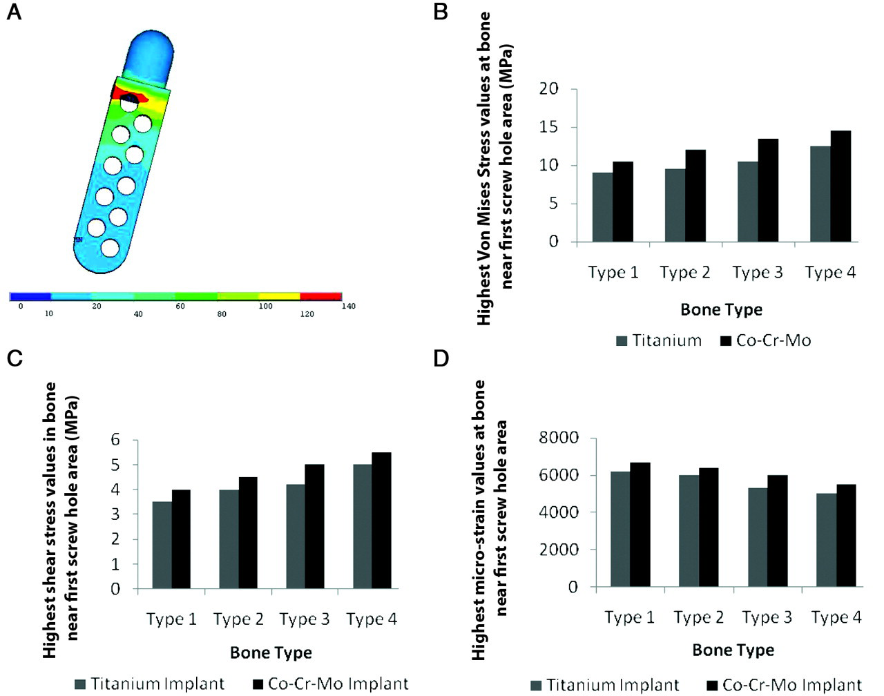
For a successful implant, the stress generated at the implant should be less than the ultimate stress as well as the yield stress of the implant material. For the titanium implant, the highest von Mises’ stress varied between 106 and 126 MPa for different bone conditions (Type I to Type IV), and average stress values in the implant varied from 40 to 75 MPa. Highest stresses were observed adjacent to the first (closest to the joint) screw hole of the implant. It was observed that the highest von Mises’ stress did not vary greatly, although the average Young’s modulus of bone varied from 550 to 800 MPa. Compressive stress (Z direction) and principal stress also followed the same pattern in the titanium implant. Highest shear stresses varied from 47 to 60 MPa in the XZ direction, which were less than the failure stress. The average shear stress varied from 15 to 24 MPa. In the XY and YZ directions, shear stresses were not very low. For Co-Cr-Mo, the highest von Mises’ stress varied between 132 and 140 MPa, and average stress values varied between 50 and 85 MPa (Fig. 2a). Highest stresses were observed adjacent to the first screw hole of the implant. The shear stress pattern was similar to titanium; however, the magnitude was higher (although less than the failure limit).
The screws used in the fixation of the implant transfer the load from the implant to the bone during function. It was observed that maximum stress was generated at the first screw (closest to the condyle of the implant). For titanium screws in the implant, the highest von Mises’ stress varied from 121 to 129 MPa, and average stress varied from 65 to 80 MPa. For the screw that was adjacent to the first screw (closest to the condyle), the stresses were significantly lower (70 to 75 MPa). Further, the stresses observed for all other screws were much lower. The shear stress (XY plane) was significantly higher for the first screw and varied from 70 to 78 MPa. This high stress was observed at the neck zone of the screw. The stresses around the other screws were found to be much lower.
For Co-Cr-Mo screws, the highest von Mises’ stresses varied from 135 to 146 MPa, and the average stress varied from 71 to 85 MPa. The shear stress (XY plane) varied from 82 to 89 MPa. All other stress patterns were similar to those of the titanium implant; however, they were higher in magnitude. Further, the stresses were quite low for all except the first 2 screws.
The applied stress is considered to be the most important factor for the long-term success of the implant. Further, the response of the bone will depend on the applied stress. This is because, in most cases, the implant may not fail, but it can still lead to loosening due to bone resorption. The stress and strain values for both implant material types are shown in the Table.
It was observed that, for the titanium alloy, the highest von Mises’ bone stress varied from 9 to 12.5 MPa, and for the Co-Cr-Mo implant, the highest values ranged from 10.5 to 14.5 MPa. The shear stress values for the titanium alloy and the Co-Cr-Mo implant were observed to range from 3.5 to 5 MPa and 4 to 5.5 MPa, respectively. The highest microstrain values at bone ranged from 5000 to 6200 and 5500 to 6700 for both implant materials, respectively. All these stresses and strains were in the vicinity of the first screw hole area (Figs. 2b, 2c, 2d).
DISCUSSION
Highest stresses (von Mises’, principal stress, and shear stress) were always observed in the screw hole location of the implant that was closest to the condyle. This high stress may be reduced to some extent if the load can be distributed over another screw hole in the nearby locations. However, this may not be of much concern, because the stresses that were observed were lower than the safe stress limit.
We observed that the increased stress levels occurred for bone with increased density (higher Young’s modulus) for both implant materials. However, the safe stress limit is also normally higher for the bone with increased density. The same was observed in the case of shear stresses in bone for both types of implant materials. In general, the microstrain was higher at the bone adjacent to the bone-implant interface. Further, in some locations of the bone (e.g., adjacent to the first screw hole), the microstrain was much higher when compared with that in other areas. The magnitude of microstrain (> 5000) might be detrimental and may cause bone resorption. However, it is reassuring that these high microstrain values were present in small areas only. The higher microstrain is more detrimental for the bone that is much weaker. Thus, it is desirable to use titanium screws for individuals with osteoporotic bone. To minimize these high microstrains, the diameter of the screw may be increased, or 2 screws can be accommodated at the same level (i.e., height) in the implant stem.
We have previously emphasized the need for further studies related to the TMJ, including biomechanical/fatigue analysis of the implant (Kashi et al., 2006). Our present study provides us with useful information related to stress distribution and the probability of locating areas that may be most likely to cause implant failure. The limitations of our study were as follows: (1) We have considered uniform muscle forces; (2) thread design of the screws was not considered; (3) viscoelasticity of bone was not taken into account; and (4) this study was based on theoretical analysis.
Our results suggest that, for osteoporotic bone, screws made of titanium alloy are preferable. Further, the number of screws may be decreased, since those located farther from the condyle contributed only minimally toward the load-carrying capacity of the implant. If 2 screws can be accommodated at the same level on the implant (close to the condyle), there may be reductions in stress concentration on a single screw as well as the bone. This can also be helpful for reducing the strain in the location of the bone that exhibited high strain level. Additional clinical and biomechanical factors need to be considered for an improved design of the TMJ implant. Such a design should be tested biomechanically, and animal tests should be conducted before the implants can be considered clinically acceptable.
Stress Values at Bone (adjacent to the implant)
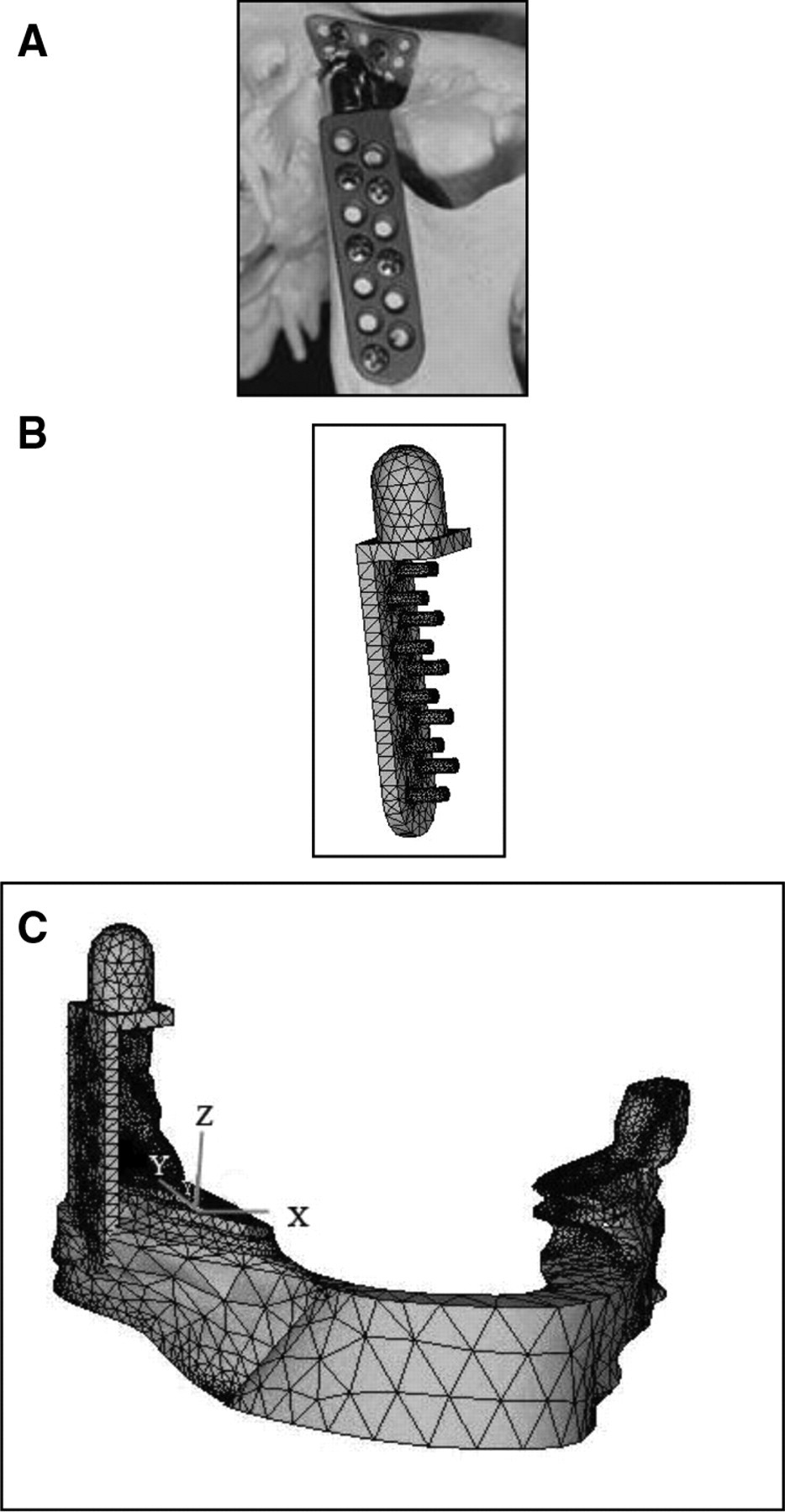
The TMJ implant and the mandible showing the FEA model.
Footnotes
Acknowledgements
No funds from any outside source were used for this study. All work for this study was done in the Department of Orthopedic Surgery and Rehabilitation Medicine at SUNY Downstate Medical Center, Brooklyn, New York. The authors thank Lila J. Lande, MPH, for her editing assistance.