
Abstract
Fiber metal laminates (FMLs) routinely outperform monolithic alloys in fatigue and conventional composites in impact, yet nominally identical FMLs made in different laboratories often differ substantially in interlaminar shear strength. The cause is almost always interfacial, and earlier reviews have treated fabrication route, surface preparation and cure cycle as separate topics. We treat the three as a single coupled system and ask which fabrication-interface pairs are compatible. Six families of surface treatment (degreasing, mechanical, chemical, coupling-agent, electrochemical and dry) and four fabrication routes are compared on cycle time, void content, lap-shear bond strength, hot/wet retention and industrial scalability. Three patterns emerge from the synthesis. The cycle-time/void envelope is dominated by autoclave-cured prepreg (180-420 min, void <1%) and by resin transfer moulding and hot-press routes at lower capital cost, while hand layup without post-cure consolidation sits off the envelope at 4-6% voids. Chromate-free surface treatments retain 52-84% of dry bond strength after 1000 h at 70 °C and 85% RH, whereas phosphoric acid anodising with a sol-gel primer retains 85-94%; the gap ranges from 1 to 42 percentage points depending on the chromate-free family chosen. Fabrication and interface treatment appear to interact, and modest nanofiller additions raise bond strength along the existing envelope rather than displacing it. The review is framed as a candidate hypothesis rather than a settled finding, and motivates further work on long-duration durability of chromate substitutes, field validation of natural-fibre FMLs, and recyclable thermoset interfaces.
Keywords
1. Introduction
Fiber metal laminates (FMLs) such as ARALL, GLARE and CARALL emerged from a clear engineering need: monolithic aluminium alloys fatigue too rapidly under tension-dominated cyclic load, and carbon fibre composites fracture too brittly under low-velocity impact. Thin metal sheets (0.3-0.5 mm) stacked with fibre-reinforced polymer plies (0.125-0.25 mm per ply) bonded through a polymer matrix combine the ductility and bearing capacity of the metal with the stiffness, fatigue tolerance and corrosion resistance of the composite.1–3 The GLARE system has flown on the upper fuselage of the Airbus A380 since 2003, and newer variants are being developed for automotive crash frames, blast-resistant containers and wind energy components. 4 The literature of the last five years has therefore widened sharply, and two recent reviews have surveyed the field: Xie et al. 5 catalogued adhesion theories and interfacial-strengthening methods for FMLs, and Bakhbergen et al. 6 mapped interface-strengthening processes, measurements and numerical models.
Performance scatter between nominally identical laminates persists even in this widening literature.7,8 The source is almost always interfacial: surface preparation, primer chemistry, void fraction during cure, or residual stress from thermal mismatch. Delamination and interfacial debonding remain the dominant failure modes under static, fatigue and impact loading.8,9 Interface engineering therefore begins long before lamination, at the metal supplier, in the chemistry of the cleaning bath, and in the geometry of the cure tool. The fabrication chain and the interface chemistry are not independent variables; they are coupled, and that coupling has rarely been treated as a first-class object in the FML literature. The present review advances this coupling as a working hypothesis rather than a settled finding, and labels each claim that follows as hypothesis (H), inference from synthesis (I), or demonstrated evidence (D) so readers can distinguish the three categories.
Several recent reviews have surveyed parts of this picture. Sadighi et al.
8
and Asundi & Choi
10
catalogued the impact and fatigue behaviour of GLARE-class systems. Costa et al.
4
summarised manufacturing routes and mechanical performance of thermoset and thermoplastic FMLs but treated surface engineering only in passing. Eslami-Farsani et al.
11
reviewed nanofiller-reinforced FML matrices and the interfacial mechanisms which those fillers activate, but did not connect that chemistry back to the choice of fabrication route. Xie et al.
5
organised adhesion theories and interfacial-strengthening methods, and Bakhbergen et al.
6
complemented this with a measurement-and-modelling perspective on interface strengthening. None of these works laid fabrication, surface preparation and curing on the same comparative axes. The present review raises fabrication-interface coupling as a testable hypothesis (H) for FML maturation: interface durability and laminate performance depend on the joint choice of fabrication route and surface treatment rather than on either axis alone. We organise the review around the spine fabrication → interface → performance → implications shown in Figure 1. Conceptual framework spine for FML maturation: fabrication, interface, performance and implications as coupled stages with feedback. Source: authors’ own illustration.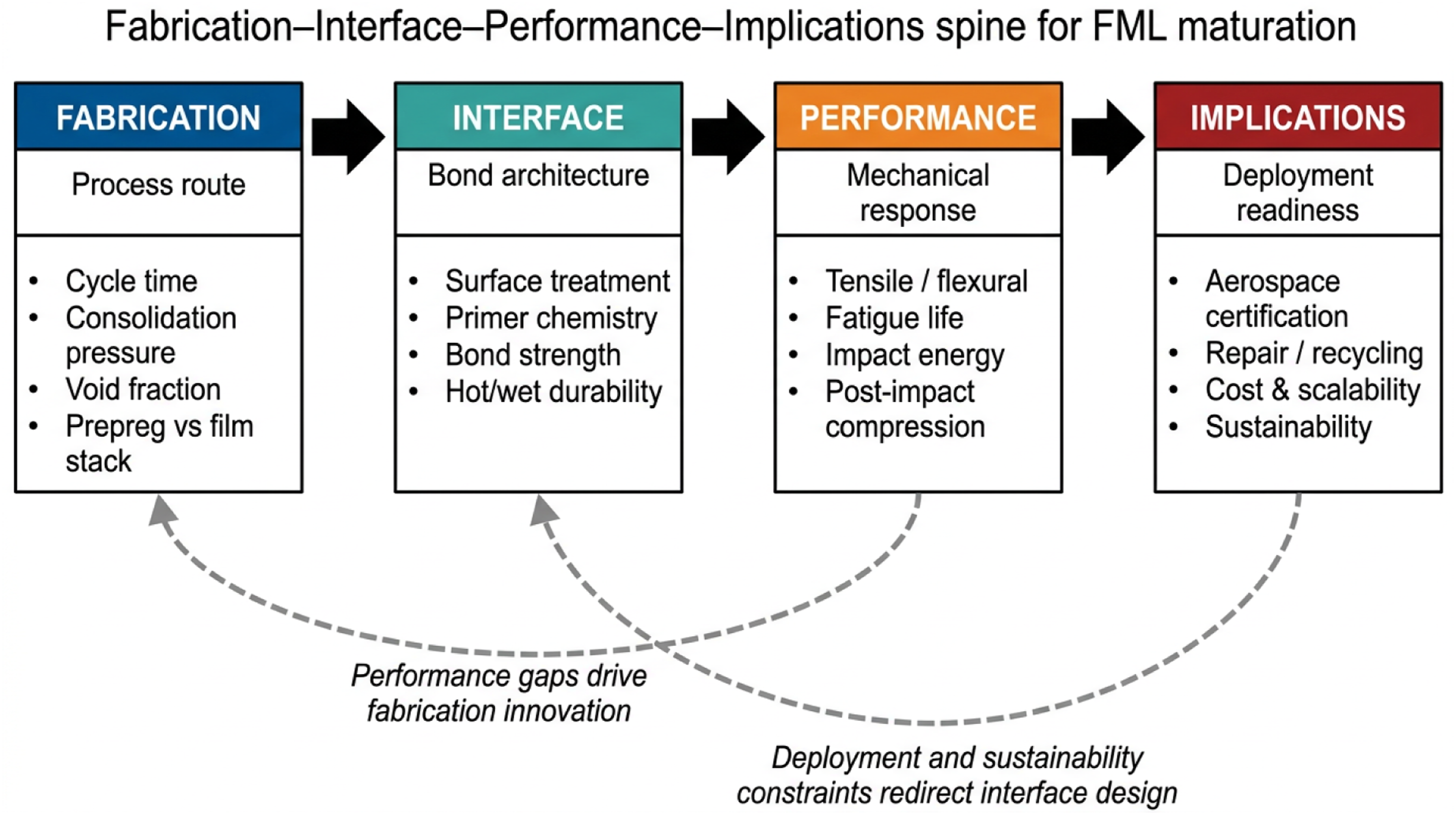
Two specific disagreements with the recent literature run through the rest of this review. Several papers report that chromate-free surface activation matches the bond durability of phosphoric acid anodising (PAA).12–14 We find that this claim rests on short-duration tests (typically under 500 h of hot/wet exposure) which does not hold when the same systems are tested for service-relevant durations.15–17 Further, natural-fibre FMLs are increasingly described as drop-in sustainable replacements for glass and aramid systems.18–20 The hot/wet, freeze-thaw and fatigue data needed to support this claim has not yet been published in field-validated form. Both points are flagged as open problems rather than as settled science.
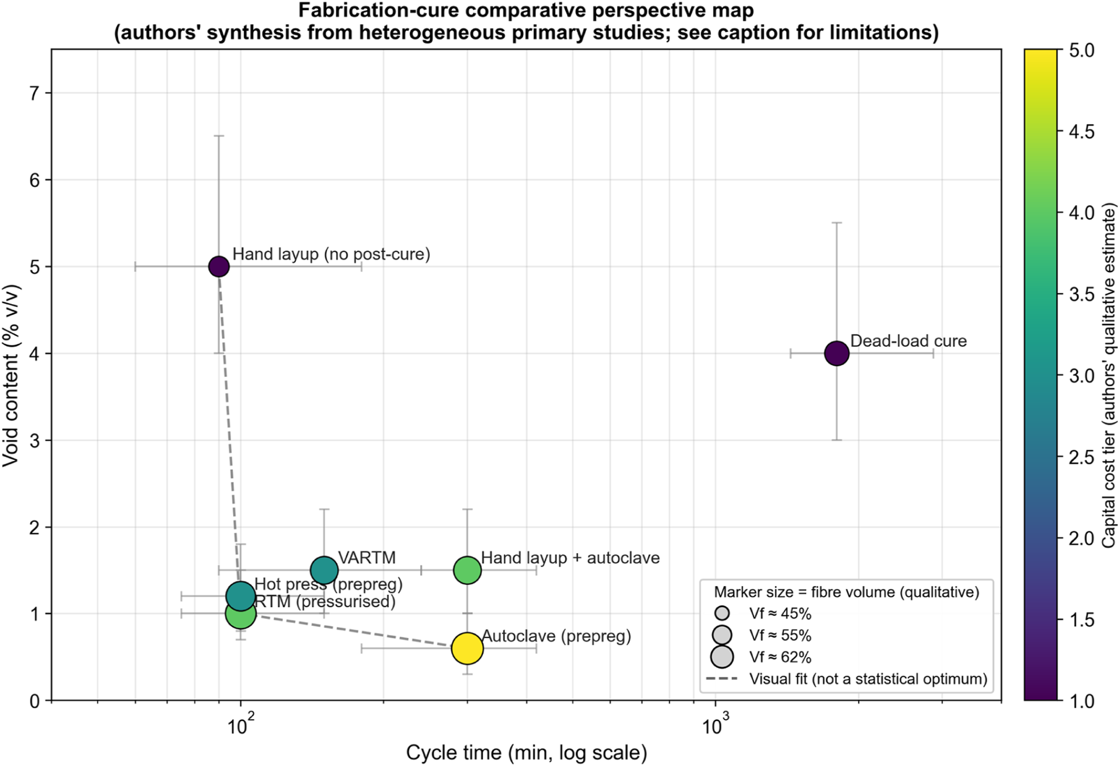
The literature surveyed here was assembled from Scopus and Web of Science searches on the descriptors “fiber metal laminate* “and “fibre metal laminate*” combined with the qualifiers “manufacture*”, “fabricate*”, “surface treatment” and “interface*”, restricted to peer-reviewed journal and review articles in English in the Materials Science, Mechanics and Engineering subject categories so as to exclude false positives from the medical, financial and computer-science uses of the FML acronym. The initial combined query returned 916 candidate records from Scopus over 2010-2026. Records were screened by title and abstract for explicit relevance to FML fabrication, interfacial characterisation or laminate performance; conference abstracts without full text, patents, and non-engineering uses of the FML acronym were excluded at this stage, leaving 245 records for full-text reading. From these, the 105 references cited in this review were chosen on the basis of (i) experimental or modelling specificity to the fabrication-interface coupling argument, (ii) reporting of quantitative bond-strength, void or durability data usable in (Figures 2 and 3), and (iii) breadth across the six surface-treatment families and the four fabrication routes. The review is presented as a critical narrative synthesis rather than a formal systematic review because the primary literature is too heterogeneous in specimen geometry, adhesive system and testing protocol to support a quantitative meta-analysis; the limits of that heterogeneity are discussed explicitly in Section 5.6. Surface-treatment comparative perspective map: lap-shear bond strength versus hot/wet retention after 1000 h at 70 °C/85% RH. Author-derived synthesis; the underlying bond-strength and retention data are compiled from the primary studies cited per row in Table 6. The placement is indicative, not predictive (see §3.1 and §5.6 for the heterogeneity caveats). Fabrication-cure comparative perspective map: cycle time (log scale) versus void content. Author-derived synthesis; the underlying cycle-time and void-content data are compiled from the primary studies cited per row in Table 5. The placement is indicative, not predictive (see §3.2 and §5.6 for the heterogeneity caveats).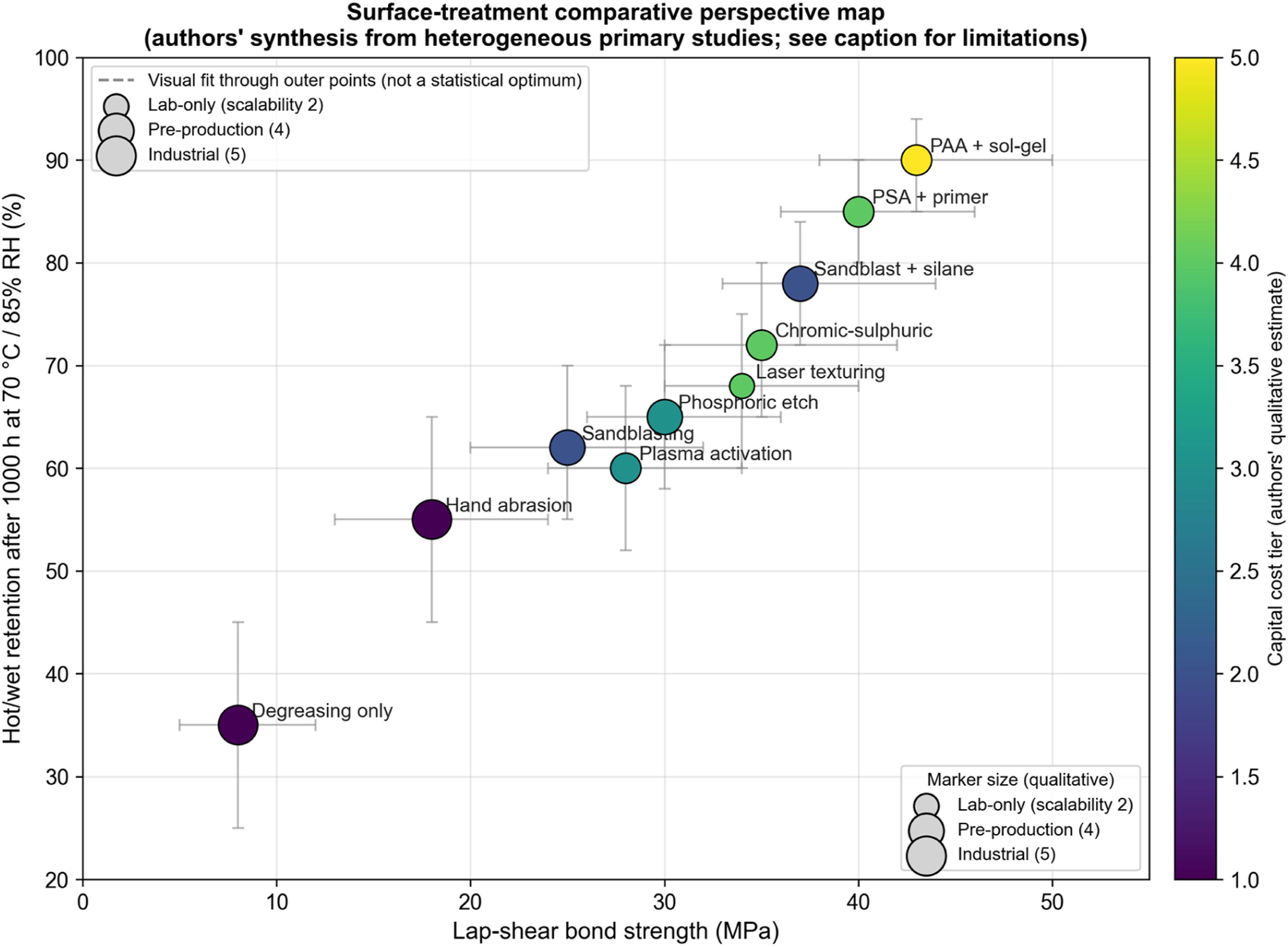
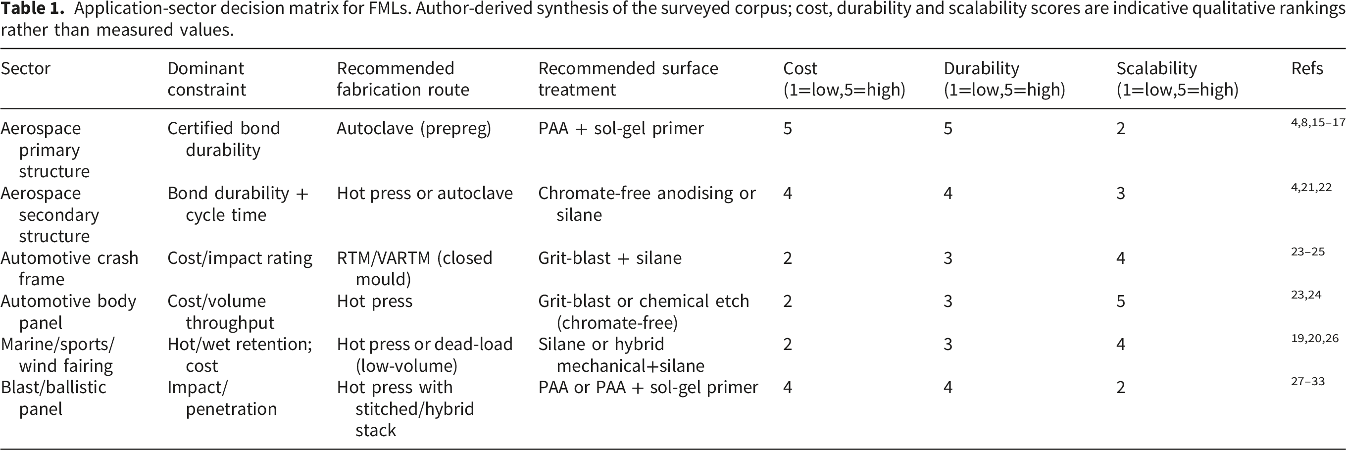
Application-sector decision matrix for FMLs. Author-derived synthesis of the surveyed corpus; cost, durability and scalability scores are indicative qualitative rankings rather than measured values.

FML fabrication workflow from material selection to finishing. Source: authors’ own illustration.
1.1 Historical development of FML
FML development began in 1978 when Delft University introduced ARALL (Aramid Reinforced Aluminium Laminate), achieving roughly 20% weight saving on the C-17 cargo door.1,2 ARALL combined unidirectional aramid fibres with thin aluminium sheets but performed poorly in compression, bending and moisture ingress. GLARE (Glass Reinforced Aluminium Laminate), introduced in 1987, replaced aramid with glass fibres, improving fatigue, impact and fire resistance, and moved into fuselage and blast-containment applications respectively.1–3 GLARE grades 1 to 6 and HS were created by varying fibre orientation and aluminium type. Figure 5 presents the classification of these established industrial FML systems alongside the metal and fibre constituents from which they are built.
In the 1990s, CARALL (Carbon Reinforced Aluminium Laminate) followed by replacing aramid with carbon fibres which raised mechanical and thermal performance for aerospace use.
4
Subsequent work substituted titanium, magnesium and steel for aluminium, including experimental FMLs from NASA, within the broader development of hybrid material concepts for aircraft structures.
34
The LEIKA project pursued forming technologies for automotive FML applications, and BMW used an FML in the 7 Series to cut roughly 130 kg from the body. Demand for FML technology continues to grow across aerospace, automotive, sports and wind energy etc. The application set is expected to widen as fabrication matures and load-bearing capability improves. Figure 6 traces the principal milestones from 1978 to the present.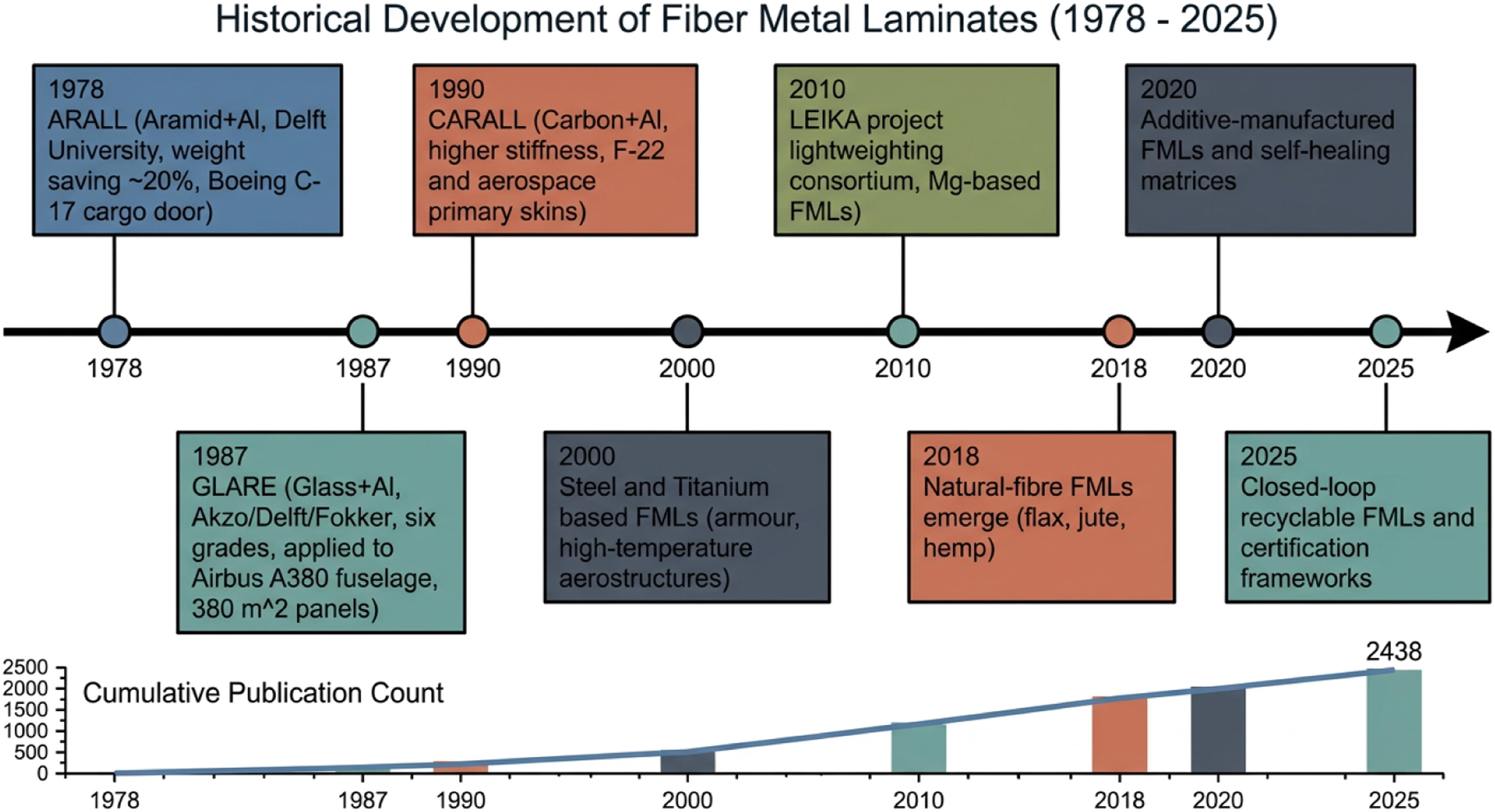
2. Components of FMLs
An FML is built from four kinds of constituents viz. A metallic alloy, a fibre reinforcement, a polymer matrix, and (optionally) a filler system added to the matrix. The properties of the finished laminate follow from the choice of each constituent and from the way they are bonded. Metals, fibres and matrices are treated in this section. Filler systems and nanomodified matrices are consolidated into Section 5.2, where they sit alongside the recent advances in nanostructured interfaces.
2.1. Metal alloys
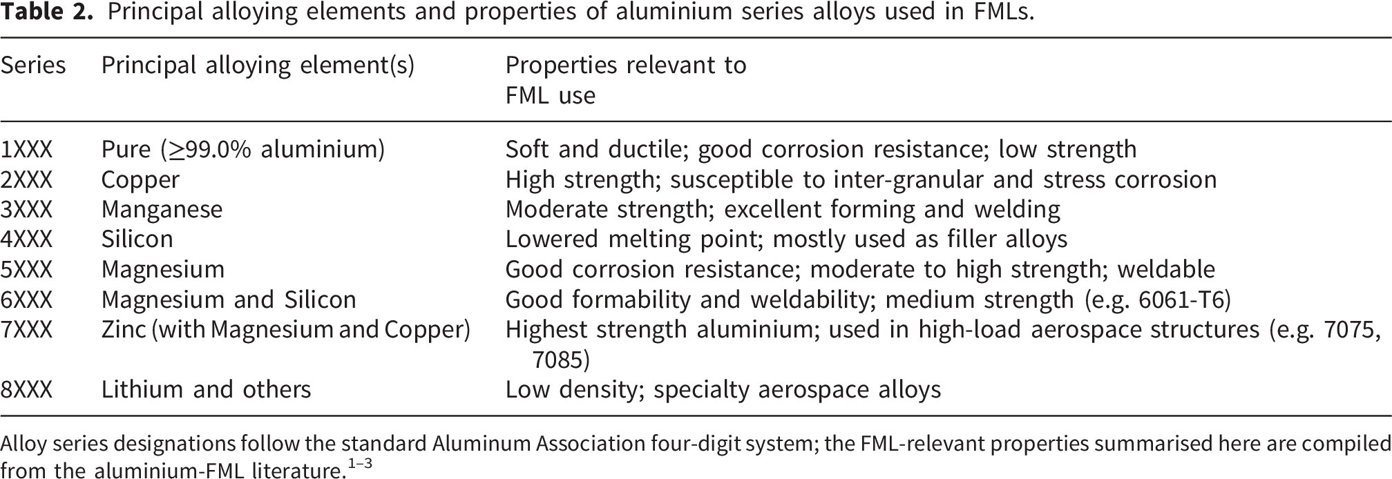
Principal alloying elements and properties of aluminium series alloys used in FMLs.
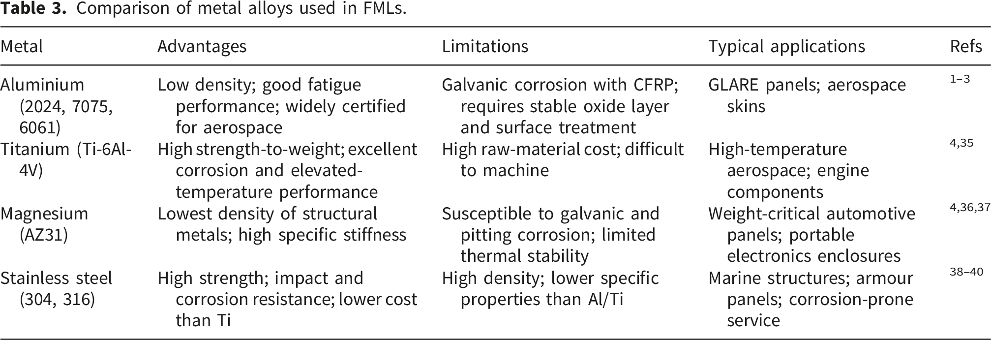
Comparison of metal alloys used in FMLs.
The metal must be compatible with the FRP layers it bonds to. The dominant compatibility constraint is the coefficient of thermal expansion (CTE); a mismatch larger than roughly 10 ppm/K builds residual stress during cure which can pull the interface apart on first thermal cycle. 22 Symmetric lay-up, controlled cure ramps and surface treatments which increase mechanical interlocking (sandblasting, etching, primer films etc.) mitigate this risk and are addressed in Section 3.1.
2.2. Fiber-reinforced polymers
Advantages and disadvantages of fibre-reinforced polymers used as the FRP layer in FMLs.
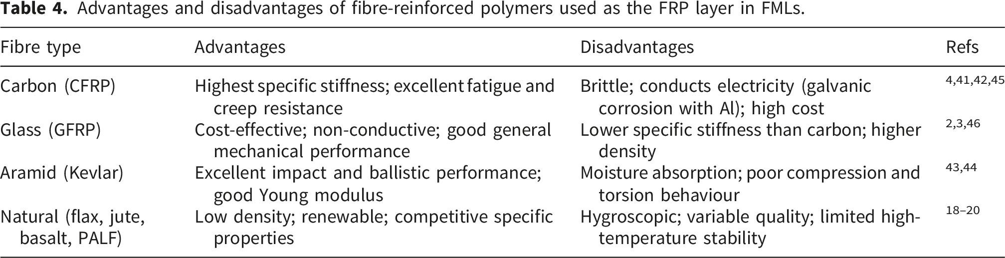
Specific properties drive fibre selection more than absolute properties. Carbon fibres (1.75-1.95 g/cm3) deliver 130-150 GPa specific stiffness, the highest of the synthetic fibres. Glass fibres (2.5-2.6 g/cm3) carry lower specific stiffness but at lower cost. Aramid fibres (1.44 g/cm3) combine low density with good impact behaviour. Natural fibres such as flax (1.4-1.5 g/cm3) and jute (1.3-1.5 g/cm3) reach competitive specific strength compared to glass despite lower absolute properties; their durability limits are addressed in Section 5. The overall weight to volume ratio of an FML follows from both the fibre choice and the metal-to-composite thickness ratio.
2.3. Matrix material
The matrix bonds the fibre and metal layers, transfers load between them, and protects against moisture, UV and chemical attack. Thermoset epoxies dominate aerospace work owing to the best combination of strength, stiffness and chemical resistance they offer. Polyester resins are cheaper and cure at room temperature which suits high-volume marine and automotive parts. Vinyl ester resins sit between the two, with better toughness than polyester and better chemical resistance than epoxy. Hardener ratios are critical viz. Epoxies use 1:1 or 2:1 (resin:hardener), polyesters use 1-2% catalyst by weight, vinyl esters and phenolics use system-specific ratios respectively. An incorrect ratio damages the matrix mechanical properties and the metal matrix interface together.
Thermoplastic matrices viz. Polyetheretherketone (PEEK), polyphenylene sulphide (PPS) and polyamide (PA6) are receiving renewed attention because they offer reshaping after forming, higher impact toughness, shorter processing cycles, and a viable end-of-life path. Reyes and Cantwell 47 showed that glass-fibre-reinforced polypropylene FMLs achieved high fracture energy across a wide range of loading rates. Vieille and Coppalle 48 later evaluated PEEK-based hybrid laminates at elevated temperature and confirmed retained impact performance. Thermoplastic FMLs require higher processing temperatures (typically 280-400 °C for PEEK), and achieving adequate interfacial adhesion without dedicated surface activation remains the central open problem.
3. Manufacturing of FMLs
Comparison of fabrication routes with cycle time, void content and Technology Readiness Level (TRL).
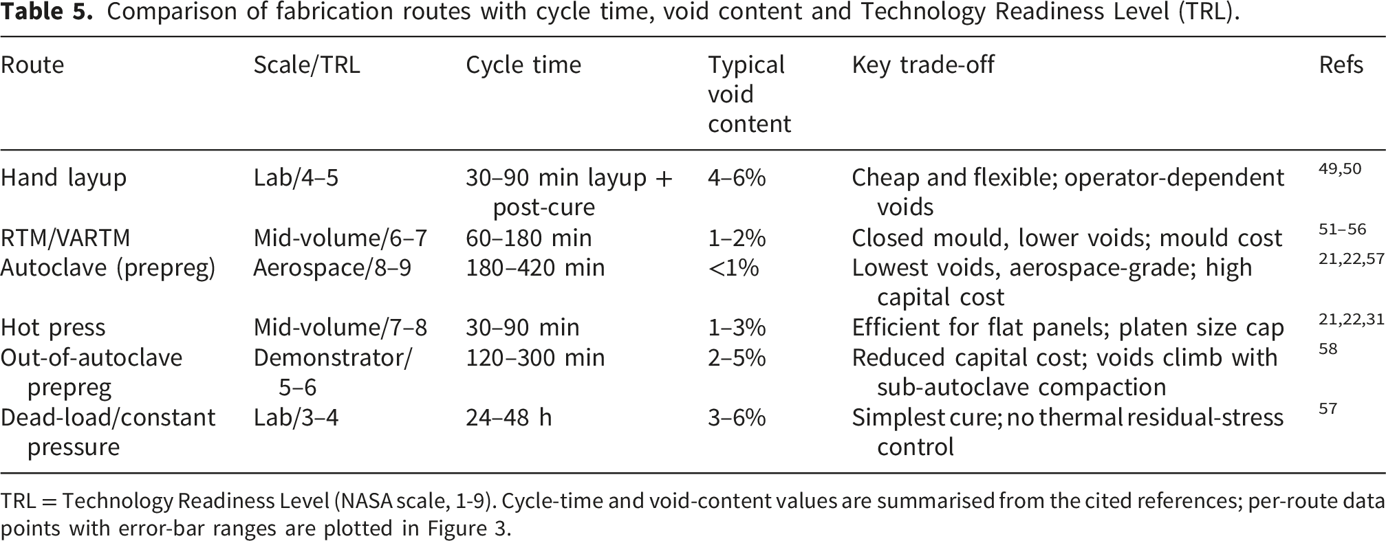
TRL = Technology Readiness Level (NASA scale, 1-9). Cycle-time and void-content values are summarised from the cited references; per-route data points with error-bar ranges are plotted in Figure 3.
Comparison of surface treatment families with lap-shear bond strength, hot/wet retention and EHS hazard ranges.
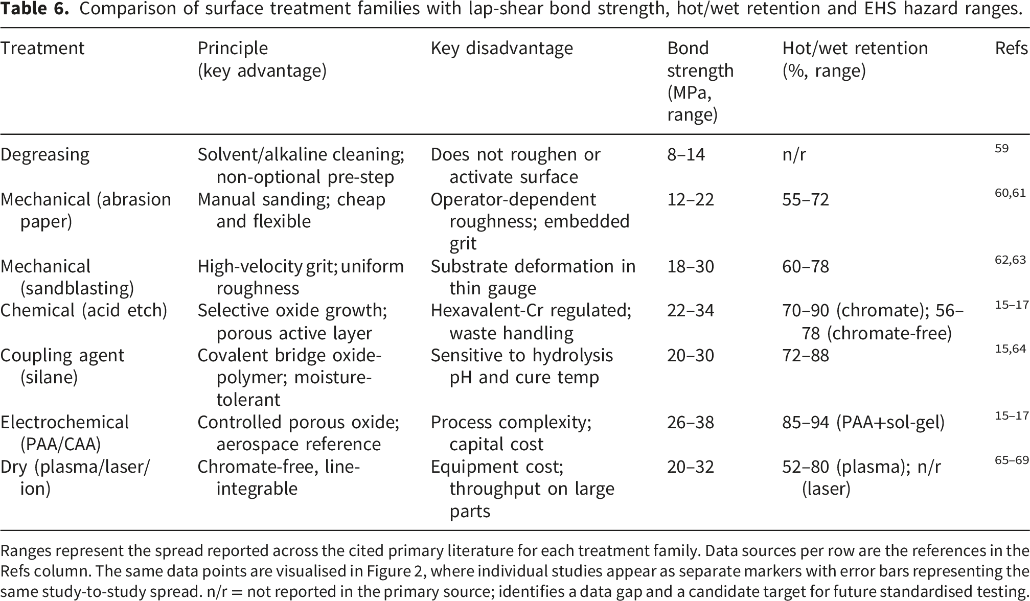
Ranges represent the spread reported across the cited primary literature for each treatment family. Data sources per row are the references in the Refs column. The same data points are visualised in Figure 2, where individual studies appear as separate markers with error bars representing the same study-to-study spread. n/r = not reported in the primary source; identifies a data gap and a candidate target for future standardised testing.
Surface treatments improve adhesion between the metal layer and the polymer matrix in three ways viz. By raising surface roughness for mechanical interlocking, by activating chemical sites for covalent or secondary bonding, and by raising surface energy for better resin wetting respectively. The six families of treatment covered here (degreasing, mechanical, chemical, coupling-agent, electrochemical, dry) trade adhesion performance against process complexity, environmental burden and scalability in different ways. Manufacturers choose among them according to the application and the production volume.
3.1. Surface treatments
Six families of surface treatment are covered in this section viz. Degreasing (3.1.1), mechanical (3.1.2), chemical (3.1.3), coupling-agent (3.1.4), electrochemical (3.1.5) and dry (3.1.6). Table 6 compares them on principle, key advantages and key disadvantages, and adds the analytical columns for lap-shear bond strength, hot/wet durability and EHS hazard. Figure 2 places them on a comparative perspective map in bond strength versus hot/wet retention; the bond-strength and retention axes are populated from the cited primary studies but combine heterogeneous specimen geometries, alloys and adhesives without normalisation, while capital cost and scalability are shown as the authors’ qualitative estimates (colour and marker size). The figure is therefore an authors’ synthesis perspective and not a statistical decision tool.
3.1.1. Degreasing
Degreasing strips oils, dust and contaminants from the metal surface so that the next treatment touches metal and not contaminant. 59 Solvent cleaning, alkaline cleaning and emulsion cleaning all work; the choice follows the contaminant and the local EHS rules. Degreasing alone does not change the surface roughness or activate the substrate, but it is non-optional. Every other treatment depends on a clean starting surface.
3.1.2. Mechanical treatment
Mechanical treatments raise surface roughness through abrasion or impact, generating micro-scale asperities which the resin can flow into and lock onto during cure. 60 Abrasion, sanding, grit blasting and shot blasting all break down the weak natural oxide and produce grooves and ridges which improve wetting and load transfer. The trade-off is consistency. Mechanical methods produce roughness which is operator and parameter dependent, and embedded abrasive particles can compromise bonding if process control is poor.
3.1.2.1. Abrasion paper
Abrasion with sandpaper roughens the metal surface and removes loosely bonded oxide. The abrasive particles cut fine scratches which raise surface area and improve resin wetting.60,61 SiC papers from P80 to P600 are standard, viz. Coarse grits (P80-P120) produce Ra of 1.5-3.0 µm and fine grits (P320-P600) produce Ra of 0.3-0.8 µm respectively. Cross-hatch sanding gives more uniform roughness and better multi-directional interlocking than unidirectional sanding. The process is predominantly manual in laboratory settings; some authors follow ASTM D2093 to improve consistency, but the pass count varies between 10 and 50 strokes across published studies. Figure 7 shows the resulting topography and illustrates the resin-penetration behaviour discussed in Section 5. The method is cheap and accessible but produces roughness which is hard to reproduce, a known limitation for aerospace work and the main reason it is not used on primary structure. Resin penetration into an abraded metal surface: capillary wetting (left) versus air-trapped pocket (right). Source: authors’ own illustration.
3.1.2.2. Sandblasting methods
Sandblasting drives abrasive particles (alumina, glass beads, or garnet) at the metal surface at high velocity.61,62 The repeated impacts strip oxide and produce a more uniform roughness than hand abrasion. Bond strength typically rises 30-60% over hand-sanded controls in lap-shear testing of aluminium-epoxy joints.61,63 Grit blasting and shot blasting use the same principle with different particle types and energies; an average particle size near 10 µm has been reported for aluminium 6061. 63 The main control variables are blast pressure, particle size, standoff distance and exposure time. Excessive pressure or exposure can deform the metal substrate or embed particles in it which is a known problem in thin-gauge aluminium FML preforms.
3.1.3. Chemical treatment
Chemical etching dissolves the metal surface selectively in an acid bath, leaving a microporous and chemically active oxide layer which the polymer matrix wets and bonds into 15. Chromic-sulphuric acid etching of aluminium (sodium dichromate 30 g/L, sulphuric acid 300 mL/L, 60-70 °C, 15-30 min) is the historical reference process. 70 It produces an oxide layer with excellent short-term bond strength, but its hexavalent chromium is regulated under REACH and OSHA standards. Phosphoric acid etching (10-12 wt% H3PO4, 20-25 °C, 20-25 min) produces a thinner but more stable oxide, and is the most common chromate-free route. Alkaline cleaning with NaOH (5-10 wt%, 50-60 °C, 1-5 min) removes the natural oxide before acid etching. Combination treatments (alkaline followed by acid) produce more uniform morphologies and higher bond strengths than single-step methods.
Two open problems persist in chemical treatment. Despite considerable effort on chromate-free chemistry, no single chromate-free etch has yet matched chromic-sulphuric performance after long hot/wet exposure (Section 5 reviews the recent evidence). Etching also produces concentrated waste streams which complicate environmental compliance, and the cost of compliant waste handling is a real barrier to adoption in cost-sensitive automotive work.
3.1.4. Coupling agents treatments
Silane coupling agents bridge the metal oxide and the polymer matrix chemically. 64 Silane molecules hydrolyse and react with surface oxides to form a thin siloxane layer; their organic functional groups bond covalently with the polymer during cure. The dual affinity raises bond strength, moisture resistance and stress transfer beyond what mechanical or chemical roughening alone achieve. Effectiveness depends on hydrolysis pH, silane concentration and cure temperature. Fedel et al. 64 and Rider and Arnott15–17 confirmed improved corrosion resistance and durability in silane-treated bonded joints. Sol-gel primers based on similar chemistry are now standard pretreatments in chromate-free aerospace work.
3.1.5. Electrochemical treatment
Electrochemical anodising, phosphoric acid anodising (PAA) and chromic acid anodising (CAA), applies an electric current to drive controlled growth of a porous oxide on the aluminium surface.15,16 The resulting oxide is thicker and more stable than any chemically etched oxide, the porosity allows deep resin penetration, and the interface tolerates years of moisture exposure. 17 PAA is now the default surface treatment for GLARE-class aerospace FMLs. Phosphoric sulphuric anodising (PSA) is used in Boeing aerospace lines and gives similar performance with reduced phosphate waste. The trade-off for all anodising routes is process complexity viz. Voltage control, bath temperature, and post-anodising rinse and primer all matter, and the equipment cost is significant.
3.1.6. Dry surface treatment
Dry treatments, atmospheric and low-pressure plasma activation, laser surface texturing and ion-beam processing etc., modify surface chemistry and topography without acid baths or chromate.65,66,69 They are attractive for sustainability and for line integration, since in-line plasma stations can be placed directly on a fabrication line. Cold (non-thermal) plasma operates with the bulk gas near ambient temperature (room temperature to roughly 100 °C) while sustaining a high electron temperature, and the non-equilibrium reactive species it generates activate the aluminium surface without thermal damage to the substrate. Davis et al.12,66 demonstrated that a plasma-sprayed coating of 60% Al-Si and 40% polyester gave bonding performance comparable to PAA in short-duration testing. De Iorio et al. 69 reported that cold plasma significantly enhanced adhesion in polymer blends and on Al 6061 substrates. Laser texturing creates well-defined micro-features but currently requires per-part programming.13,71 The shared limitations of dry methods are equipment cost, vacuum requirement (for low-pressure variants), and limited throughput on large area parts.
Table 6 summarises the six families with principle, advantages and limitations alongside the bond-strength and durability ranges drawn from the cited literature. Figure 2 presents the same comparison as a comparative perspective map in lap-shear bond strength (MPa) versus hot/wet retention (% of dry baseline after 1000 h at 70 °C/85% RH). The bond-strength and retention axes are taken directly from the cited primary studies but are not normalised across specimen geometries, alloys or adhesives. Capital cost is shown as the authors’ qualitative estimate (colour axis). The figure makes the broad trade-off visible without claiming a statistical optimum. PAA paired with a sol-gel primer dominates in performance and durability but at high capital cost; mechanical methods dominate in cost but at compromised consistency and durability; dry methods sit on the upper envelope on bond strength but lose ground on hot/wet retention compared to PAA.
3.2. Fabrication of fiber metal laminates
Four fabrication routes are compared in Table 5 viz. Hand layup, resin transfer moulding (RTM/VARTM), autoclave processing, and hot pressing. Figure 3 places them on a perspective map in cycle time (minutes) against void content (% v/v), with fibre volume fraction and capital cost shown as the authors’ qualitative estimates (marker size and colour), not measured quantities. Out-of-autoclave (OoA) prepreg processing is included here for completeness through a single illustrative data point in Figure 8 from Wowogno et al.,
58
which shows that voidage and laminate thickness rise sharply once compaction conditions depart from autoclave-grade pressure. This supports the position of OoA processing relative to the autoclave point on the fabrication map. A comprehensive review of OoA process families, filament winding, and additive-manufacturing routes for FMLs is outside the scope of this review, and readers active in those areas are referred to the dedicated reviews on each technique. Voidage and thickness evolution of out-of-autoclave epoxy prepreg with compaction temperature (reproduced from Wowogno et al.
58
under CC-BY 4.0).
3.2.1. Hand layup
Hand layup is the most common method for laboratory-scale FML fabrication.49,50 It uses a release-coated mould, manually stacked plies of fibre reinforcement and metal sheet, and resin applied and consolidated with a roller. Figure 9 illustrates the process step by step. The method is cheap and flexible; orientation, geometry and stacking sequence are all easy to vary. The cost is operator dependence viz. Void content typically reaches 4-6% without post-cure consolidation,
49
and repeatability is poor. Hand-laid preforms are usually post-cured in an autoclave or hot press to consolidate them and reduce void content. Hand layup sequence for FML fabrication. Source: authors’ own illustration.
3.2.2. Resin transfer molding
Resin transfer moulding (RTM) is a closed mould process.51–53 Dry fibre preforms and metal layers are stacked in a two-part mould, the mould is closed, and resin is injected under pressure (PRTM) or drawn in by vacuum (VARTM).54–56 The resin impregnates the fibres and cures under controlled conditions. RTM produces lower void content (typically 1-2%) and better fibre volume fraction control than hand layup, with less operator dependence and minimal post-finishing. The method is well suited to mid-volume production of complex shapes.
3.3. Curing of fiber metal laminates
Curing turns the wet preform into a structural laminate by polymerising the matrix under controlled temperature and pressure. The choice of cure method controls fibre volume fraction, void content, residual stress and dimensional stability, and therefore the interlaminar strength of the finished laminate.
3.3.1. Dead load or constant pressure
Dead-load curing applies constant pressure at room temperature for 24-48 hours. 57 It is the simplest cure method and is most often used downstream of hand layup. It produces acceptable bonding for low-demand parts and minimises void content for the geometry it can support. The cost is cycle time and the absence of any thermal control of residual stress.
3.3.2. Autoclave techniques
The autoclave is the workhorse for aerospace-quality FMLs. Figure 1121,22,57 The system combines a heated pressure vessel with a vacuum bag, breather and bleeder around the laminate (Figure 10). The breather removes air and volatiles; the bleeder absorbs excess resin. Figure 10 shows the corresponding vacuum-bag stack from which the autoclave loads its work. The design challenge is the temperature pressure time cycle viz. It must polymerise the resin completely, hit the target fibre volume fraction, and produce a void-free laminate, all without building residual stress from the metal-FRP CTE mismatch. Modified cure cycles (slow ramps, intermediate dwells) reduce these stresses but extend the cycle time. Vacuum-bag setup for FML curing. Source: authors’ own illustration. Autoclave curing system for FML manufacturing. Source: authors’ own illustration.

3.3.3. Hot press technique
The hot press applies controlled heat and pressure between two platens to bond stacked metal and FRP layers.21,22,31 The cycle can use constant or staged pressure; the laminate polymerises and consolidates in a single step. The method is efficient for flat panels and produces low void content with strong interfacial bonding. The main limitation is the platen size which caps the part dimensions.
3.4. Post-treatment
Cured FMLs almost always carry residual stresses from the thermal mismatch between metal and FRP. These stresses leave the aluminium in tension and the fibres in compression at room temperature which shortens fatigue life. Two groups of post-treatments address this. Mechanical post-stretching, used on early ARALL, pulls the aluminium past its yield to redistribute residual stress. Post-cure thermal treatment below the original cure temperature relieves residual stress and improves dimensional stability without matrix degradation.
Cured FMLs also need machining and inspection. Drilling can cause delamination, burr formation, or fibre pull-out unless cutting speed and feed are tuned to the laminate. Water-jet cutting reduces the heat-affected zone but introduces moisture at cut edges and needs sealing. Quality inspection typically uses ultrasonic C-scan to detect voids and disbonds, with visual inspection and tap testing as supplements. Edge sealing and protective coatings follow where the service environment requires them.
4. Analysis of common fabrication configurations
Verified FML configurations from the literature (15 rows) with metal, fibre, matrix, surface treatment, fabrication route and recommended use case.
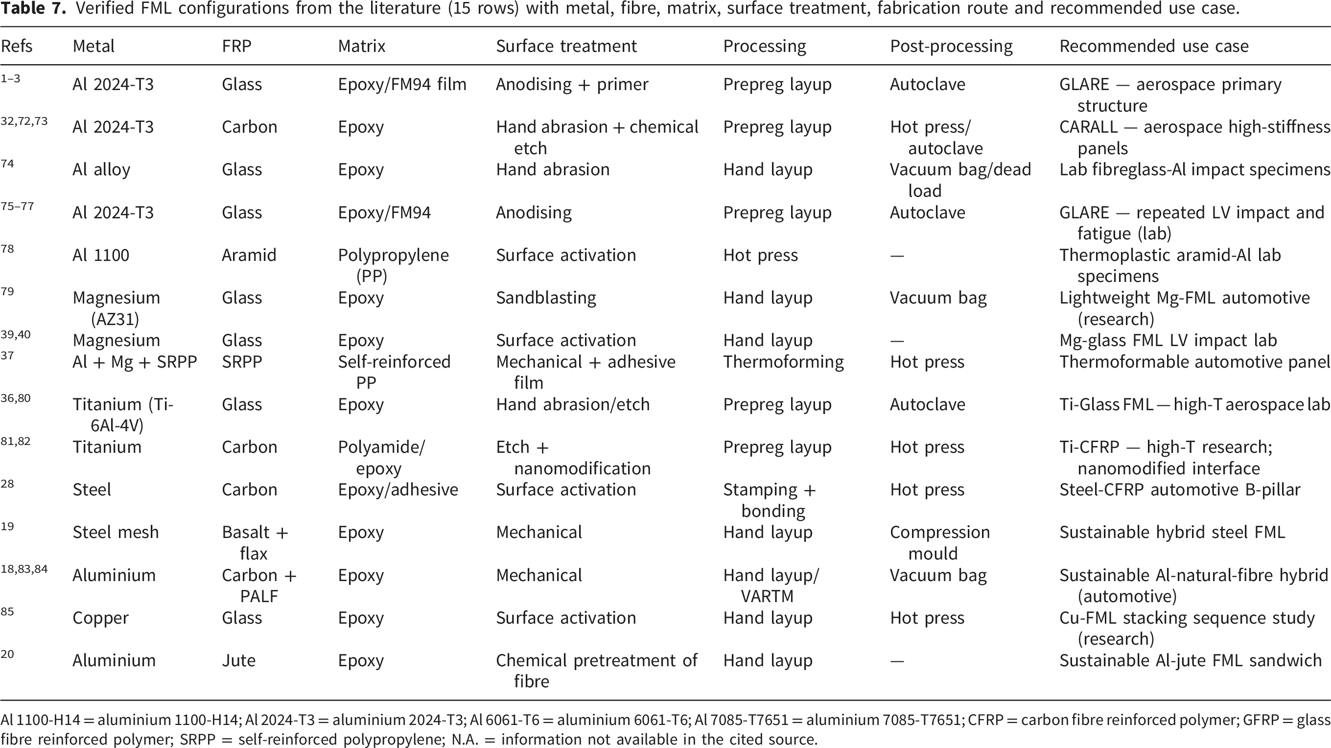
Al 1100-H14 = aluminium 1100-H14; Al 2024-T3 = aluminium 2024-T3; Al 6061-T6 = aluminium 6061-T6; Al 7085-T7651 = aluminium 7085-T7651; CFRP = carbon fibre reinforced polymer; GFRP = glass fibre reinforced polymer; SRPP = self-reinforced polypropylene; N.A. = information not available in the cited source.
Aluminium 2024-T3 dominates Table 7, mostly owing to its aerospace history and certified status. Where alternative metals appear, they occupy specific niches viz. Titanium for high-temperature work, magnesium for weight-critical automotive panels, and stainless steel for corrosion-prone environments respectively. Glass and carbon fibres are the most common reinforcements; aramid appears mostly in ballistic and high-velocity impact work.86–89 Epoxy resins and prepregs dominate the matrix column, reflecting the established certification base for thermoset FMLs.
Three patterns recur across Table 7. Hybrid surface treatments (mechanical followed by chemical, or chemical followed by silane) consistently outperform single-step treatments on interlaminar strength and on residual strength after damage. 90 Additional consolidation pressure during vacuum bagging—for example, spring-loaded systems—gives reliable improvements in void content and bond strength even when the underlying fabrication route remains hand layup. Fracture behaviour of hybrid metal/composite stacks is similarly configuration-dependent. 91 No single row is universally optimal; the right configuration depends on the intended application, the production volume and the certification path. Section 5 examines how recent work is moving each of these patterns forward, and Section 4.1 maps the same patterns onto sector-specific recommendations.
4.1. Application-sector decision matrix
The configurations in Table 7 cluster into a small number of application sectors, each with a different dominant constraint. Aerospace primary structure is dominated by certified bond durability and damage tolerance, and the matrix selects autoclave-cured prepreg with phosphoric acid anodising and a sol-gel primer. Aerospace secondary structure and stabiliser leading edges can relax the cycle-time constraint and accept hot-press routes with silane or chromate-free anodising. Automotive crash-frame and bumper assemblies 92 are dominated by cost and cycle time and accept higher voidage in return for closed-mould RTM/VARTM with grit-blast plus silane on lower-cost aluminium series, or with steel where impact rating is the limit.23,25 Automotive body panels weighted by volume favour hot press with grit-blast pre-treatment. Marine, sports and wind-blade fairing applications tolerate dead-load or hot-press consolidation with chromate-free silane systems but are sensitive to hot/wet retention. Table 1 consolidates these as a decision matrix on cost (1–5), durability (1–5) and scalability (1–5), with each row labelled by the dominant constraint and the recommended fabrication-interface combination. The matrix is presented as an author-derived synthesis of the surveyed corpus rather than as a predictive recommender; Section 5.6 records the heterogeneity caveats that govern its use.
5. Recent studies in fiber metal laminates
Recent FML work has pulled in three directions viz. More sustainable constituents (natural fibres), more capable interfaces (nanofiller-modified matrices and novel surface engineering), and more manufacturable architectures (hybrid stacks, recyclable bonds) respectively. The section is structured around those three directions in 5.1 to 5.3 and then closes with hybrid architectures (5.4) and the open problem of repairability and recycling (5.5). Where the evidence is strong it is reported as such; where it is short-duration or single-laboratory it is flagged so. Figure 2 places the surface-treatment approaches discussed in 5.3 on a continuous trade-off map in bond strength versus hot/wet retention; Figure 7 shows the nanoscale resin-penetration mechanism which the surface treatments aim to enable.
Reported nanofiller systems in FMLs with bonding mechanism, property change and Surface-prep controlled? Flag.
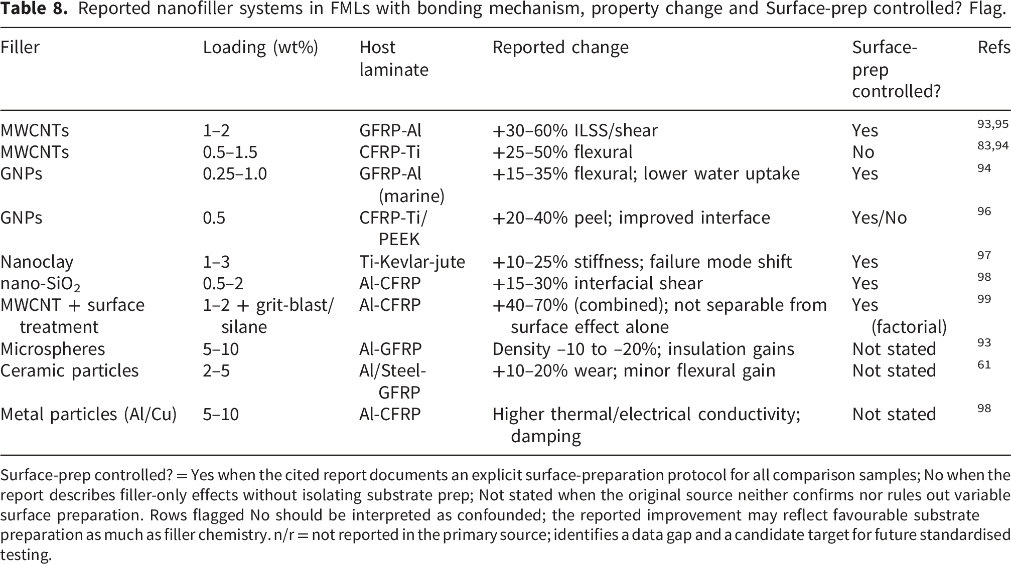
Surface-prep controlled? = Yes when the cited report documents an explicit surface-preparation protocol for all comparison samples; No when the report describes filler-only effects without isolating substrate prep; Not stated when the original source neither confirms nor rules out variable surface preparation. Rows flagged No should be interpreted as confounded; the reported improvement may reflect favourable substrate preparation as much as filler chemistry. n/r = not reported in the primary source; identifies a data gap and a candidate target for future standardised testing.
Alternative fibre families investigated in FMLs: systems tested, reported outcomes and comparison against conventional reinforcements.

Field-validated hot/wet, freeze-thaw and long-term fatigue data are largely absent for the natural-fibre systems above; see Section 5.1 for the durability mechanism discussion.
5.1. Natural-fiber-based FMLs
Natural fibres (flax, jute, sisal, basalt, pineapple leaf and hemp) are increasingly substituted into FMLs to lower the carbon footprint and the cost of the laminate. Xiao et al.18,83,84 developed aluminium-carbon-pineapple leaf hybrid laminates with promising behaviour under low- and high-velocity impact and favourable viscoelastic response, and a follow-up review by the same group 23 mapped recent developments in hybrid FMLs for the automotive industry. Kirubakaran et al. 26 produced a titanium-basalt-flax hybrid FML and showed that natural fibres can raise vibration damping and lower weight without compromising essential mechanical properties. Karuppasamy et al. 19 combined woven stainless-steel mesh with basalt-flax fibres via hand layup and compression moulding for a competitive dynamic and mechanical response. Haq et al. 20 produced jute-based FMLs reinforced with chemically treated plain and twill fabrics and reported improved tensile, flexural and impact performance. More recently, Awd Allah et al. 24 compared natural- and synthetic-fibre FMLs for vehicle panels and showed that the property gap narrows once the matrix and interface chemistry are jointly optimised. Padmanabhan et al. 100 evaluated hemp/bamboo/basalt woven FMLs under Fick-type moisture diffusion and confirmed that stacking sequence and natural-fibre selection together govern moisture-driven property loss—an explicit durability data point that natural-fibre FMLs had previously lacked. The alternative-fibre families and FML systems used by these groups are listed in Table 9 with their reported outcomes and a comparison column against conventional reinforcements.
5.2. Nanofiller-reinforced and modified matrices
The discussion of fillers is consolidated with the recent advances in nanofiller-modified interfaces here, since both topics address the same physical question: how does a low-concentration secondary phase in the matrix change the metal-polymer bond? FRPs are the primary load-bearing reinforcement in an FML (continuous fibres at 50-65 vol% of the laminate thickness). Fillers are secondary additions dispersed in the matrix at low concentrations (typically below 5 wt%). They are discontinuous and modify specific matrix properties—fracture toughness, thermal conductivity and interfacial bonding—without forming a continuous reinforcing phase. Common fillers include microspheres, ceramic particles, metal particles and a growing list of carbon-based nanofillers (MWCNTs, graphene oxide, graphene nanoplatelets and nanoclays). Microspheres lower laminate density and improve thermal insulation; carbon nanotubes raise mechanical strength, stiffness and electrical and thermal conductivity; ceramic fillers raise wear resistance and hardness; metal fillers raise thermal and electrical conductivity and damping. Khurram et al.93,95 reported improved interfacial bonding and joint strength with 2 wt% MWCNTs in epoxy resin under vacuum compression, with comparable MWCNT-driven gains reported in basalt-fibre FMLs. 101 Keshavarz et al. 94 showed that 0.25% GNPs raised flexural strength and reduced water absorption in marine FMLs. Naveen et al.97,102 investigated titanium-based FMLs reinforced with Kevlar and jute fibres in graphene-modified epoxy and showed that optimised graphene loading and compression pressure enhanced tensile, flexural, peel-strength and low-velocity impact behaviour, with a nanoclay follow-up showing matched gains in stiffness and damage tolerance. Guo et al. 98 reported nano-SiO2 surface modification with combined experiment and molecular-dynamics simulation, with improved interfacial shear strength. Two recent studies extend the argument directly to the coupling question. Wang et al. 96 reinforced the interlaminar interface of carbon-fibre/aluminium laminates with graphene and reported a clear improvement in interfacial response only when the metal substrate was independently prepared. He et al. 99 applied a two-step strategy combining MWCNT modification with metal surface treatment in the same laminate and reported that the combined scheme outperformed either route alone, which supports rather than demonstrates the coupling hypothesis. Table 8 lists representative filler systems, loadings, host laminates and the property changes they produced. The Surface-prep controlled? Flag was assigned by reading each cited paper’s experimental section: Yes where the cited study used a single documented surface-preparation protocol across all comparison samples (so that the filler effect could be isolated from substrate preparation); No where the cited study either varied surface preparation across samples or did not describe it; Not stated where the original source neither confirmed nor ruled out variable preparation. The flag is the authors’ judgement and would benefit from independent confirmation by the original groups. The full reported range spans 5-180% interlaminar improvement; the larger gains (100-180%) come predominantly from rows flagged Surface-prep controlled? = No, where the contribution of substrate preparation cannot be cleanly separated from the effect of the filler chemistry itself. Nanofiller dispersion quality is a major and rarely-controlled source of variability in the cited studies; poorly-dispersed agglomerates act as defect sites rather than reinforcement, and the absence of dispersion characterisation (TEM, dynamic light scattering, rheology) in many primary reports limits cross-study comparison. Mapping these results onto the surface-treatment perspective map of Figure 2 supports a candidate hypothesis (H): in studies where surface preparation is controlled, modest nanofiller additions raise bond strength along the existing envelope by typically 5-50%; the larger improvements reported elsewhere (100-180%) may be confounded by concurrent surface-preparation effects, although a direct factorial separating the two contributions is absent from the corpus reviewed and the hypothesis is therefore testable rather than demonstrated.
5.3. Novel surface engineering methods
Several novel surface engineering routes have appeared in the recent literature. Üstün et al. 103 introduced cellulose paper as an interlayer in CARALL laminates fabricated by vacuum bagging and reported improved mechanical properties at lower cost and better sustainability. Balkundhi et al. 14 used Electric Discharge Machining (EDM) to texture aluminium 2024-T3 in CARALL systems, producing a hydrophobic surface with superior interfacial strength compared to conventional surface treatments. Hydrophobicity normally impedes resin wetting and would be expected to reduce bond strength; the favourable bond strength reported by Balkundhi et al. 14 therefore likely reflects the geometric interlocking provided by the EDM-textured topography rather than the surface chemistry, and the mechanism is not yet fully resolved. Self-healing coatings, atmospheric plasma activation and femtosecond laser micro-texturing etc. Are all reaching usable maturity but are still confined to single-laboratory demonstrations.13,69,71
5.4. Hybrid structural architectures
Beyond modifying constituents and interfaces, several groups have redesigned the laminate at the architectural level. Pedram et al. 27 produced a sandwich combining an autoclaved aerated concrete (AAC) core with FML skins and showed improved ballistic resistance under blunt impact loading. Vasudevan et al. 85 examined copper-based FMLs reinforced with CNT-modified epoxy and found that the copper layers drove stacking-sequence-dependent mechanical responses while the CNTs improved interfacial bonding.
5.5. Interface repairability, recyclability, and fatigue
Repairability, recyclability and fatigue performance have become active research lines as FMLs move into mainstream production. Maguire et al.
104
proposed a methacrylate adhesive film which bonds the metal and composite together for service while still allowing separation at end of life, a critical step for any thermoset-based FML to participate in a circular material economy. Wiedmann et al.21,22 evaluated modified curing cycles in steel-CFRP FMLs and showed that optimised thermal schedules raised fatigue resistance by lowering residual stress at the interface. Kim et al.28,29 developed a stitched CARALL fabricated by VARTM and compared stitched, perforated and pristine laminates; stitched FMLs exhibited stronger delamination resistance and superior impact tolerance. Stitching restrains delamination propagation through-thickness rather than raising the intrinsic chemical adhesion of the metal-polymer interface; the higher delamination resistance and impact tolerance therefore reflect a structural reinforcement mechanism (I) rather than an interfacial-chemistry improvement, and the two should be distinguished when comparing through-thickness reinforcement against surface-treatment improvements. Ulus et al.
25
complemented this with bonded, bolted and hybrid bonded/bolted joints in aluminium/composite FML retrofit panels under hydrothermal ageing and showed that hybrid joints retain a usable load envelope after exposure that pure bonded joints lose. Mrzljak et al.
105
demonstrated that combining DIC strain mapping with electrical-resistance measurement enables reliable in-situ detection of fatigue-related damage states in notched FML specimens (Figure 12). Condition monitoring setup for FML fatigue testing: (a) digital image correlation with thermography camera and (b) electrical resistance measurement (reproduced from Mrzljak et al.
105
under CC-BY 4.0).
5.6. Limitations of the synthesis
Three limitations of the synthesis presented in Sections 3 to 5 must be stated explicitly so that readers do not over-interpret the comparative maps. First, the bond-strength and hot/wet retention values plotted in Figure 2 are drawn from primary studies with heterogeneous specimen geometries: single-lap shear (ASTM D1002), wedge test (ASTM D3762), double-cantilever beam (ASTM D5528) and short-beam interlaminar shear (ASTM D2344) coexist in the corpus, and the bond-strength axis is therefore not strictly comparable between rows. Second, adhesive systems differ widely between studies: FM-73, FM-94, EA9696, AF-555, in-house epoxy formulations and thermoplastic PEEK or PPS bonds appear with no shared baseline, and the chromate-free retention range of 52-84% (Section 6) accordingly subsumes adhesive-formulation variability as well as surface-chemistry variability. Third, testing protocols vary in exposure temperature, humidity and duration: 1000 h at 70 °C and 85% RH is the most commonly cited hot/wet condition (used here as the reference) but a non-trivial fraction of the corpus uses 500 h at 50 °C, salt-spray (ASTM B117), or freeze-thaw cycles instead. Where possible the data presented in Tables 6 and 8 are grouped by alloy (2024-T3, 6061-T6, 7075-T6, Ti-6Al-4V) and by adhesive class (FM-family, EA-family, in-house epoxy) so that within-group comparisons remain defensible. Across these caveats, the comparative perspective maps (Figures 2 and 3) and the application-sector matrix (Table 1) should be read as indicative author-derived synthesis rather than predictive models, and the coupling hypothesis itself remains testable rather than demonstrated until a controlled factorial study reports both axes in a single experimental campaign.
6. Conclusion
Three patterns emerge from the synthesis which together support the candidate hypothesis that fabrication and interface decisions should be coupled rather than treated separately. The cycle-time/void envelope is dominated by autoclave-cured prepreg with cycle times of 180-420 minutes and void content below 1 percent; resin transfer moulding and hot pressing sit on the same envelope at lower capital cost, while hand layup without post-cure consolidation lies well off the envelope at 4-6 percent voids. Hot/wet durability remains the limiting factor for chromate-free surface treatments. Chromate-free systems retain 52-84 percent of dry bond strength after 1000 hours at 70 °C and 85 percent relative humidity, with the lower end reported for plasma activation and the upper end for silane and hybrid systems. Phosphoric acid anodising paired with a sol-gel primer retains 85-94 percent under the same exposure. The gap therefore ranges from 1 to 42 percentage points depending on the chromate-free family chosen. Fabrication choice and interface treatment appear to interact, and the corpus reviewed does not let either axis alone predict the laminate’s performance envelope.
The third pattern is the candidate mechanistic principle behind the coupling hypothesis. Adding modest nanofiller loadings to a poorly wetted interface does not appear to rescue it; nanofillers raise bond strength along the existing envelope rather than displacing it (H). Where surface topography produces complete capillary wetting, fillers add load-transfer paths and crack-bridging behaviour; void-trapping pockets cannot be compensated by filler chemistry alone (I). Selecting an aerospace-grade surface treatment with a hand-layup process therefore yields a laminate whose performance is capped by the void content of the layup. We position fabrication-interface coupling as a candidate testable principle for FML design rather than as a demonstrated finding, since the corpus reviewed does not contain a controlled factorial varying both fabrication route and surface treatment in the same study.
For practitioners, the practical recommendation that follows from the synthesis is to pair the surface treatment to the production volume and EHS constraint first, and the fabrication route to the part geometry and cycle-time budget second. Direct experimental evidence for the coupling hypothesis, viz. A controlled factorial varying both fabrication route and surface treatment in the same study, is absent from the corpus reviewed and is itself a recommended future direction. Future work motivated by this review falls into three concrete directions, viz. (i) Coordinated round-robin testing of chromate-free surface treatments at multi-thousand-hour hot/wet, salt-spray and freeze-thaw exposures, (ii) field-validated durability and fatigue programmes for natural-fibre FMLs at service-relevant durations, and (iii) reversible bonding chemistries, thermoplastic matrices and selective delamination techniques for closed-loop recycling of thermoset-based FMLs.
Footnotes
Acknowledgements
The authors gratefully acknowledge the support provided by the Department of Mechanical and Aerospace Engineering, United Arab Emirates University.
Ethical considerations
Not applicable. This is a review article. No experiments involving human participants, animals or primary data collection were conducted.
Author contributions
Afsar Husain: Literature survey, data collection and manuscript drafting. Sanan H. Khan: Supervision, critical analysis and manuscript revision. Abdel-Hamid I. Mourad: Manuscript review and technical guidance.
Funding
The authors received no financial support for the research, authorship, and/or publication of this article.
Declaration of conflicting interests
The authors declared no potential conflicts of interest with respect to the research, authorship, and/or publication of this article.
Data Availability Statement
No new data were generated or analysed in this study. All information is derived from published literature cited within the manuscript.