






Abstract
Intelligent unmanned mining technology is very important for modern coal mining to improve the safety and efficiency. Autonomous navigation cutting technology is an emerging trend of intelligent fully mechanized coal mining technology. This paper presents the construction method of the accurate 3D coal seam model as determination of the navigation map of the shearer. The cutting plane implicit function was induced to generating the section of the coal seam model, and the coal seam roof and floor boundary curves were achieved by the cubic B-spline curve fitting. By comparing the optimization effects of the BP neural network, the RBF neural network and the genetic algorithm, the genetic algorithm is finally selected for the shearer drum cutting trajectory optimization to reduce the gangue rate and improve the coal recovery rate. The simulation steps of the genetic algorithm are described in the paper, whose experimental results show that after 100 generations of optimization by the genetic algorithm. The maximum error of the cutting trajectory is reduced to 0.017 m, which is significantly better than the cubic B-spline fitting results before optimization. The findings of the paper provide the theoretical and technical support for the development of intelligent navigation mining technology of the shearer.
1. Featured Application
Established a time-efficient and accurate shearer cutting trajectory optimization system via high-precision 3D coal seam modeling, improved KNN algorithm for roof/floor boundary extraction, and cubic B-spline fitting combined with genetic algorithm optimization, providing a reliable technical solution for autonomous navigation cutting of intelligent shearers.
2. Introduction
With the continuous growth of global energy demand and the great progress of mining technology, unmanned intelligent mining technology has become a key driving force for the transformation and upgrading of the coal industry. Intelligent fully mechanized mining equipment, such as the shearer, the armored face conveyor (AFC),and the hydraulic supports, are critical to achieve unmanned intelligent mining.1,2 Although significant progress in equipment monitoring and remote control has made, 3 there are still some deficiencies in autonomous decision-making and dynamic adaptive control of the shearer under complex strata, which limits the shearer overall operation efficiency and safety.4,5
Autonomous navigation cutting technology is a new intelligent mining technology. 6 This technology aims to make use of a pre-constructed digital coal seam model as the navigation map to drive the shearer with the abilities of autonomous cutting, intelligent decision-making, and cooperative operation, which represents the future trend of the intelligent fully mechanized mining technology. 7 The traditional shearer memory cutting technology has limit adaptive adjusting cutting ability to folded coal seam, which affects continuous operation efficiency of the shearer. 8 The traditional cutting trajectory planning only focuses on the working face direction, neglecting the comprehensive optimization in the operation direction and the advance direction of the coal seam, which makes it difficult to ensure a high coal recovery rate while effective avoiding over-cutting into rocks. 9 Therefore, the optimization strategy of the shearer cutting trajectory based on the coal seam navigation map is particularly critical. It not only requires to consider the accuracy and adaptability of trajectory planning, but also needs to consider the mining efficiency and the economy of resource recovery.10,11
In order to overcome the shortcomings of the memory cutting technology the most used currently, Tan 12 et al. recorded the characteristic points of the motion path of the shearer during the manual teaching process to reduce the large amount of useless information captured by the sensors, and used a common mathematical fitting method to fit the stored cutting path points, by which the smoothing of the cutting path can improve the operational stability of the shearer. Wang 13 states that the memory path points are divided into regular smooth points and movement change points, and the manual moving distance is used as the recording unit, which greatly reduces the amount of data recorded and sifts out the repetitive data. Li 14 et al. proposes a particle swarm optimization algorithm based on adaptive learning (ALPSO), which transforms the trajectory planning problem into a multi-objective optimization problem. Although the method of “artificial teaching” has been greatly improved, it is still a passive detection and regulation, which can cause great economic losses and safety hazards in the actual production process. Therefore, it is necessary to find a method that can actively and effectively detect or predict the shearer operating in a reasonable planned trajectory. In order to realize automatic height adjustment of the shearer cutting drums, Chen 15 et al. used a deep long and short term memory neural network, which can strengthen the memory ability of the cutting path and can predict the possible continuation of the cutting trajectory when the current operating state of the shearer remains unchanged, while keeping the original data volume unchanged. Grehl 16 et al. proposes a robotic method for mine mapping, modelling, assistance and safety assurance. Li 17 et al. proposes an inner spiral algorithm integrated with the Priority Internal Spiral Coverage (PISC) algorithm for full-coverage path planning, which effectively avoids obstacles, reduces redundant paths, and enhances sweeping efficiency. The algorithm’s performance is validated through simulation experiments. Shamsudin 18 et al. presents a two-stage hybrid A* path planning method, which effectively reduces memory and execution time consumption by using a low-resolution global map and a high-resolution local map. Dong 19 et al. proposes a virtual coal-rock interface model via the artificial potential field method, assuming coal seam gravitational forces and rock layer repulsive forces on the drum with differential weighting for interface construction. Notably, accuracy validation remains unaddressed. Chai 20 et al. established a three-dimensional coal-rock model with geological faults, simulated the cutting process by incorporating the shearer’s feeding mode and operational procedures, and sequentially connected the key points representing roof distribution to form the cutting path. Li 21 et al. investigates the key technologies for virtual operation and cutting trajectory planning of shearers based on Unity3D, and proposes an automatic height adjustment strategy that relies on adjusting the rotation direction of the shearer’s drum, offering practical guidance for actual production. Based on this, Hao 22 et al. constructed a full-parameter position and attitude digital twin model of hydraulic supports using Unity3D and Runge–Kutta algorithms, laying a data-driven foundation for real-time posture control of longwall equipment. In this context, the urgent issues to address include achieving adaptive adjustment of the shearer’s position state and adaptive planning of cutting trajectories according to coal seam distribution in the mining face. Miao and Ge 23 further constructed a complete theoretical framework and system for digital twin-based navigation and cutting motion planning of shearers, and adopted reinforcement learning algorithms to realize autonomous iteration and optimal decision-making of cutting motion in virtual-real interactive scenarios. Aiming at the floor step mutation and insufficient dynamic adaptability of planning paths in complex thin coal seams, Zhang et al. 24 presented a continuous planning method for shearer cutting floor based on working face step model. This method combined Bayesian state estimation and multi-pass rolling prediction to conduct online correction of geological data, and designed a layered current-based automatic height adjustment strategy to cope with rock stratum disturbance. Xie 25 et al. proposed a virtual memory cutting method based on armored face conveyor (AFC)shape prediction, according to the obtained dynamic fluctuation of the shape in the vertical and horizontal working face, the position and cutting information of the shearer during operation can be controlled and predicted in advance, and the memory cutting template can be adjusted and modified in time. A more stable, accurate and timely memory cutting of the uneven coal seam is realized. Zhang 26 et al. proposed a complete shearer propulsion path calculation method, which simulates all possible propulsion paths of the subsequent rock chips, and has obvious advantages over memory cutting. Wei et al. 27 further developed an adaptive tracking control method based on a combination of linear quadratic regulator (LQR) and error band control strategies, where switching thresholds were optimized using a marine predator algorithm. The method achieved high coal recovery while ensuring safe cutting trajectory tracking, demonstrating better efficiency than traditional strategies. For boom-type roadheader equipment, Zhang et al. 28 proposed an improved NSGA-II-based trajectory planning method with bi-objective optimization of cutting length and turning angle, which effectively improved roadway forming quality and autonomous operation performance. Dong et al. 29 integrated multi-source geological perception with trajectory planning and control, using an improved ant colony algorithm to optimize cutting paths under complex geological conditions, significantly enhancing tunneling efficiency and tracking accuracy. Meanwhile, Lijuan 30 et al. and Meichen 31 et al. adopted discrete element and bidirectional coupling methods to simulate the coal falling process of cutting drums in complex seams, analyzing the dynamic coal falling trajectories and forces. Their studies revealed that by optimizing drum structure and motion parameters. These results highlight that the lump coal rate and loading efficiency can be significantly improved by refining drum structure and working parameters.
In this study, a three-dimensional high-precision coal seam geological model with a real-time updating mechanism is constructed, and an advanced cutting trajectory planning and optimization algorithm centered on the genetic algorithm (GA) is employed to provide more intelligent and accurate cutting path schemes for the shearer. The genetic algorithm features favorable global search performance, strong resistance to premature convergence, and flexible constraint embedding capability. Within the complex nonlinear geological scenarios of coal seams addressed in this work, it demonstrates more suitable application advantages over particle swarm optimization (PSO) and deep learning methods. 32
3. Coal seam model construction
3.1. Construction of coal seam model as the initial navigation map
The flowchart of the coal seam 3D geological modeling is shown in Figure 1. The process of constructing a comprehensive three dimensional geological model incorporates four types of original data sources as inputs, namely, the geological map of the coalfield, the geological profiles, the geophysical results, and the drill data. With the aid of Geographic Information System (GIS), the geological map of the coalfield undergoes geometric correction, vectorization of geological boundaries, and division of geological objects in sequence. Geological profiles are vectorized and analyzed for their properties. Structural points and lines are extracted from geophysical results and combined with location data. Drilling data are defined in terms of data structure and filtered. The processed results are modeled through four paths: modeling of geological surfaces, modeling of geological structures, supplemental construction modeling, and drilled columnar modeling. Finally, all model inputs are integrated to generate a 3D geological model of the coal seam. Flowchart of 3D Geological Modeling of the coal seam.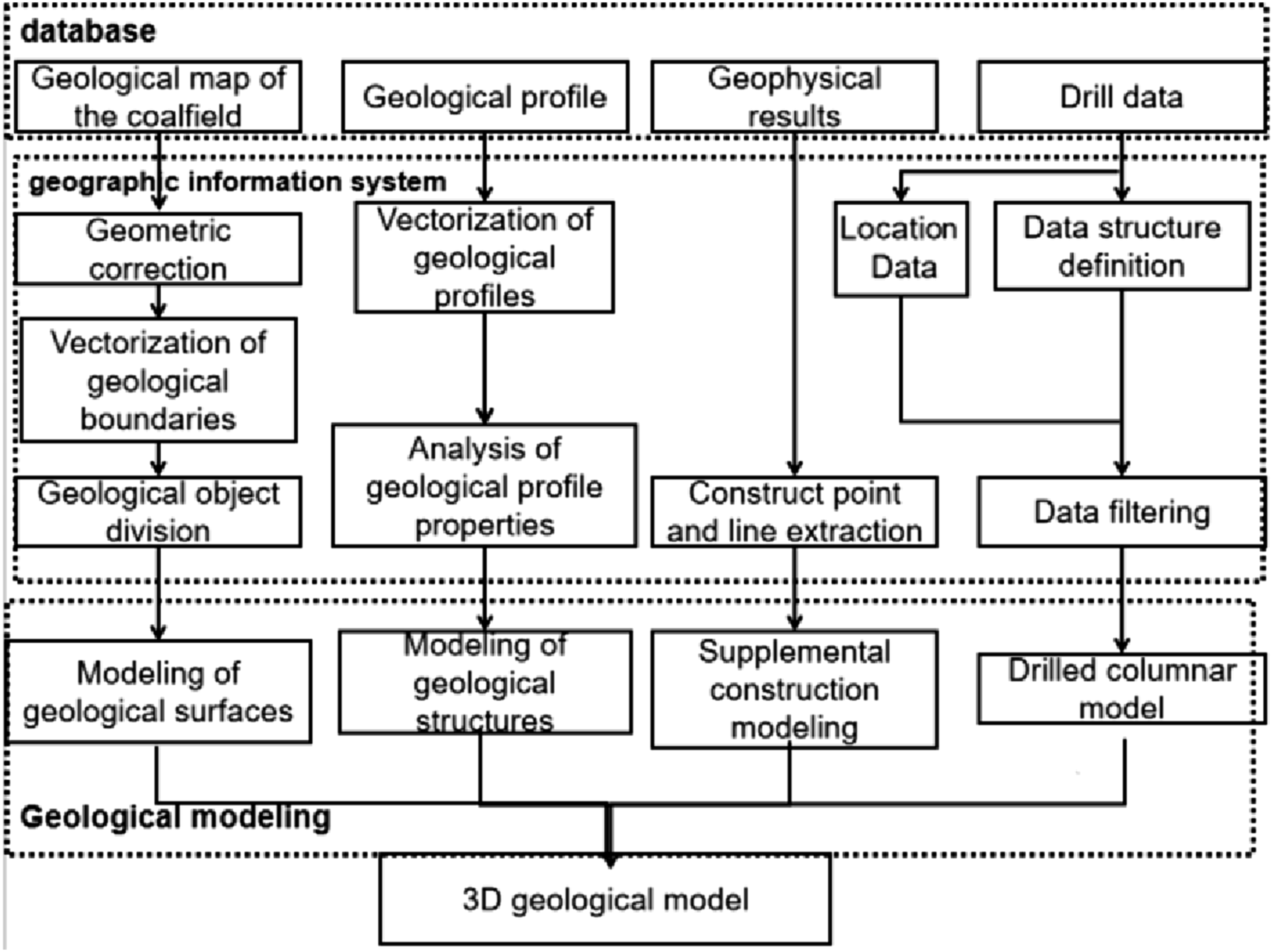
3.2. Navigation map updating based on real-time probing data
The Coal-seam Simultaneous Localization and Mapping (C-SLAM) technology is employed to enhance the accuracy of the initial coal seam model. Specifically, a non-contact ground probing radar is adopted for coal-rock interface recognition, with the radar antenna maintained 300–400 mm from the working face coal wall. Continuous detection along the working face enables acquisition of three-dimensional geological information on coal-rock folds and undulations, achieving a detection accuracy of ∼50 mm. To refine the model for shearer cutting navigation, coal seam thickness is calculated via the pre-constructed model, while the thickness of the to-be-mined seam is predicted using a valuation method. Selected thickness values are interpolated for calibration, and real-time coal-rock interface information is collected by ground-penetrating radar and integrated into the model database, realizing real-time model updates.
To balance accuracy and computational efficiency, model updating is implemented in a progressive and local manner along the working face advancing direction, synchronized with the shearer cutting cycle (0.6–1.2 m per cycle) instead of continuous global updating. The updated local model serves as input for trajectory planning: boundary data are first processed via cubic B-spline fitting to generate smooth roof and floor curves, which are then optimized using a genetic algorithm for trajectory refinement, forming a sequential coupling mechanism between model updating and trajectory generation. Furthermore, a pipelined strategy is adopted, with parallel execution of model updating and trajectory optimization for adjacent segments, ensuring real-time performance and avoiding operational delays in engineering applications.
4. Generation of coal seam roof and floor boundary curves
4.1. Construction of a section of the coal seam model
The shearer cuts the coal wall along the working face back and forth by its both cutting drums, whose cutting depth is 0.6 m to. 1.2 m along the advancing direction of the working face in an operation cycle, as shown in Figure 2 To control the drums autonomously, the roof and floor boundary lines should be determined for the coal seam. Operation cycles of the shearer.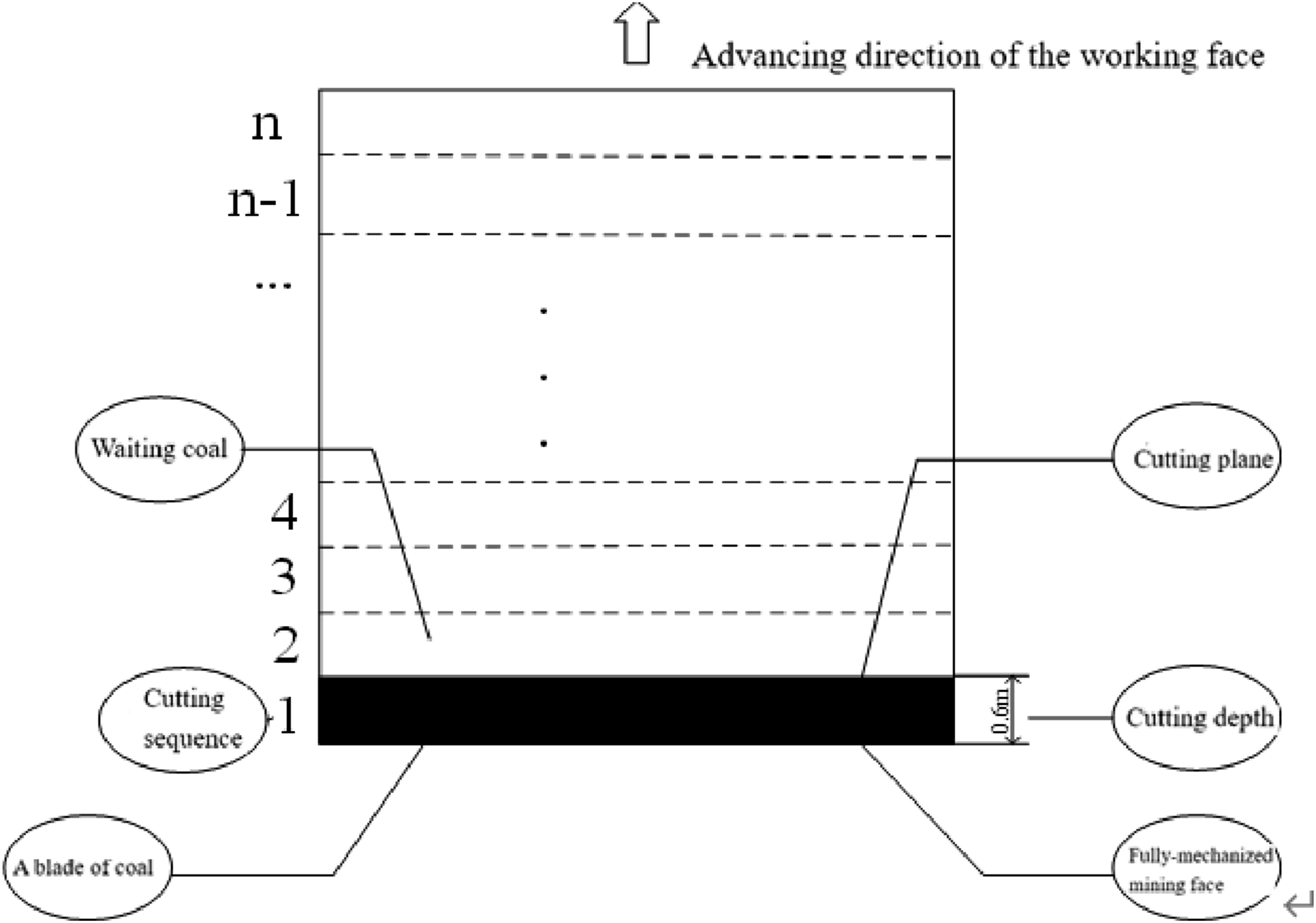
The section of the coal seam model is generated by the algorithm based on the cutting plane implicit function, which is able to convert the three-dimensional polyhedral models, such as spheres, cylinders, cones and quadratic surfaces, into two-dimensional plane models. The spatial coordinates

The steps of the plane cutting implicit function algorithm are: (1) Generate values for all triangle vertices of the shearer cutting cycle model by (2) Form the intersection of a polygonal plan by
As shown in Figure 3, the cutting process can be categorized into ten cases of cutting a triangular in the tangent model. Cases of cutting a triangular.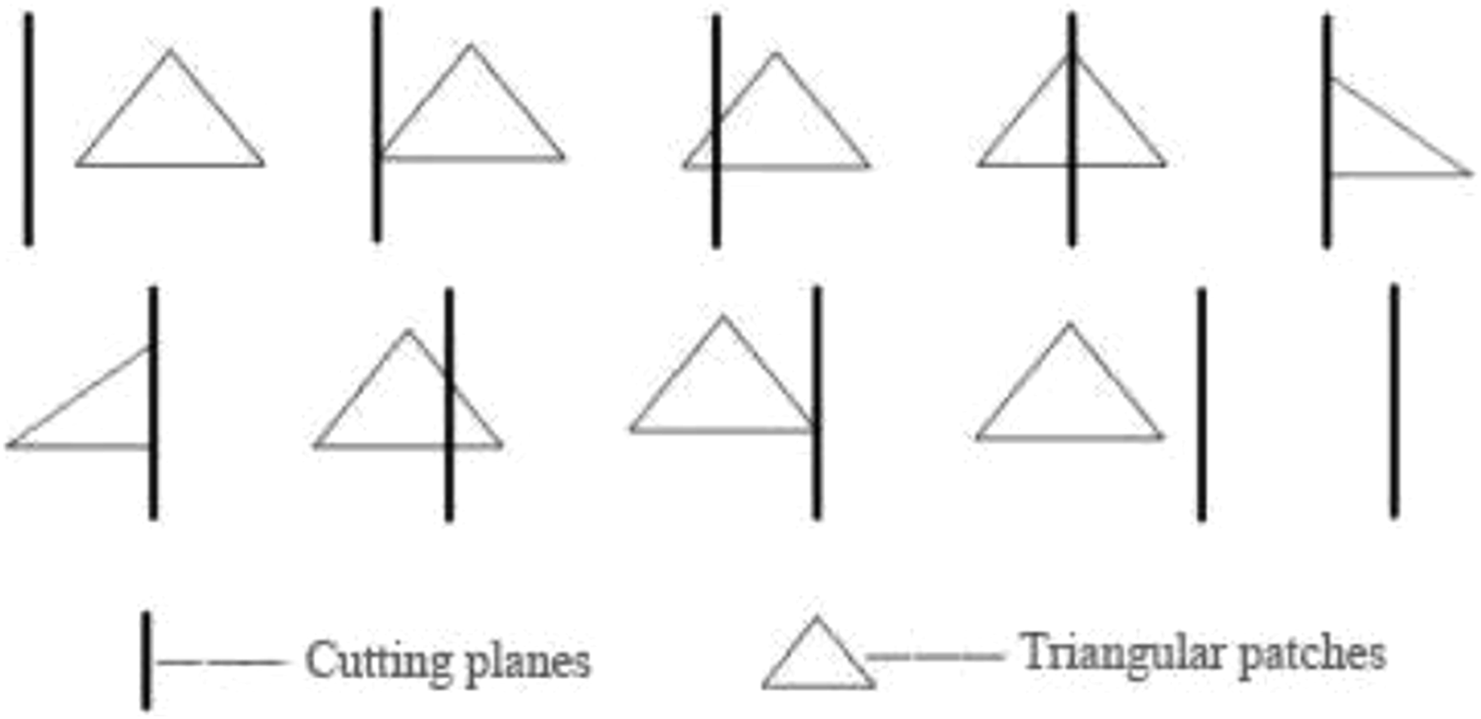
The intersection coordinates are derived from Equation (2). These coordinates are calculated to define the boundaries of triangular facets which form the working face of the coal seam cutting by a uniform depth. As illustrated in Figure 4, the red face in the right side denotes the cyclic cutting plane of the working face. The implicit-function cutting algorithm provides a precise and efficient method for obtaining the cutting plane all intersection points. The working face cutting plane of the coal seam.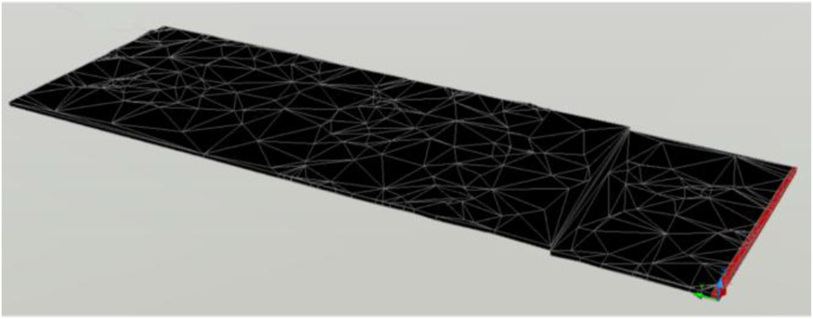

4.2. Roof and floor boundary curves generation algorithm
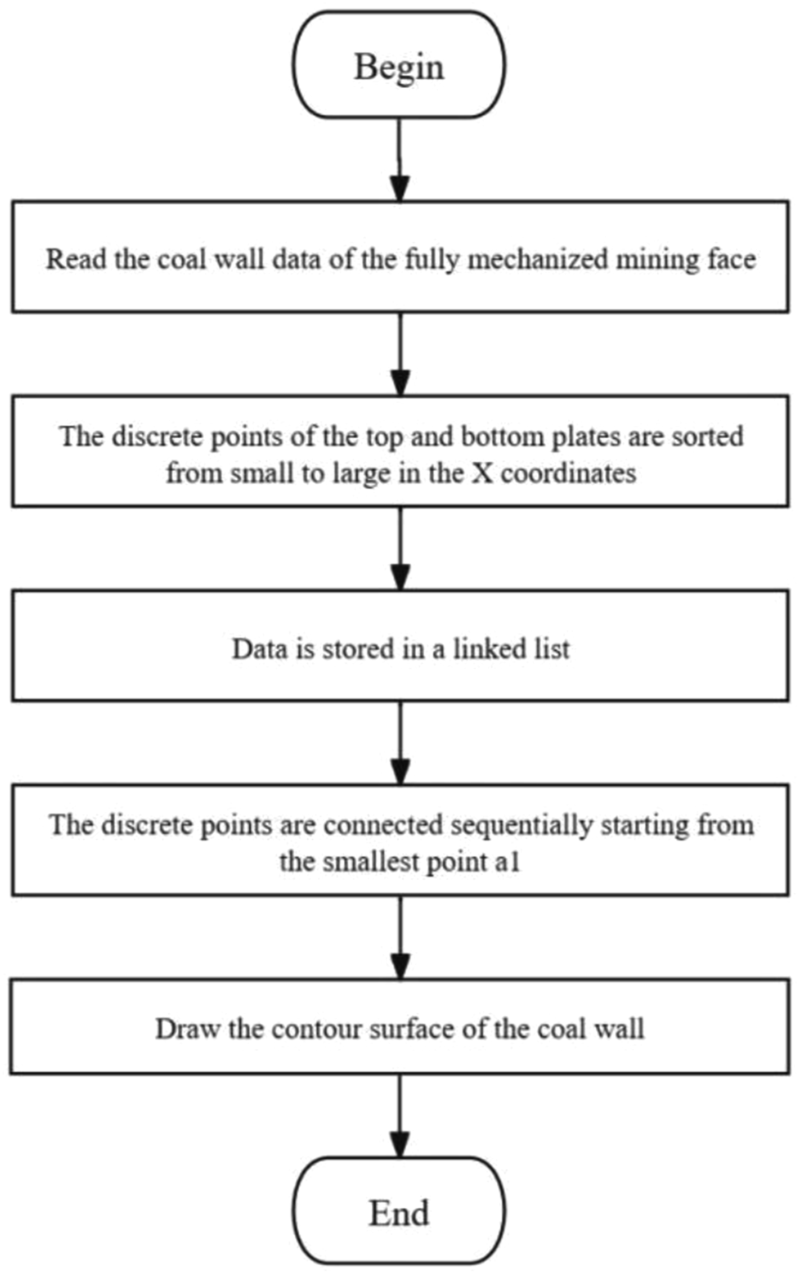
After the establishment of the cutting plane model of the working face, the roof and floor boundary lines of the coal seam need to be determined in advance for further controlling the cutting drums of the shearer. The conventional Convex Hull Algorithm has a limited number of applications. When the cutting plane is complicated and disorderly, the conventional Convex Hull Algorithm is likely to result in the extraction error of the coal seam roof and floor boundary lines, whose errors grows exponentially. Therefore, this paper introduces the improved K-Nearest Neighbor Algorithm (KNN) to determine the coal seam roof and floor boundary lines, which can effectively overcome the defects of the conventional Convex Hull Algorithm. The flow chart of the improved KNN algorithm is shown in Figure 5: (1) Read the data of the coal seam working face, classify the coal seam distribution, and label the geological data. (2) Sort the working face plane data from the smallest to the largest in terms ofx coordinates, sort the well categorized data of the coal wall profile surface from smallest to largest. (3) Store the data of the roof and floor boundary lines of the working face in the order of the first to the last. (4) Set the (5) Draw the outline line of coal wall in counterclockwise order, connect Algorithm flow chart of improved adjacent sorting method.
The coal seam model is sliced into Coal seam roof and floor boundary lines.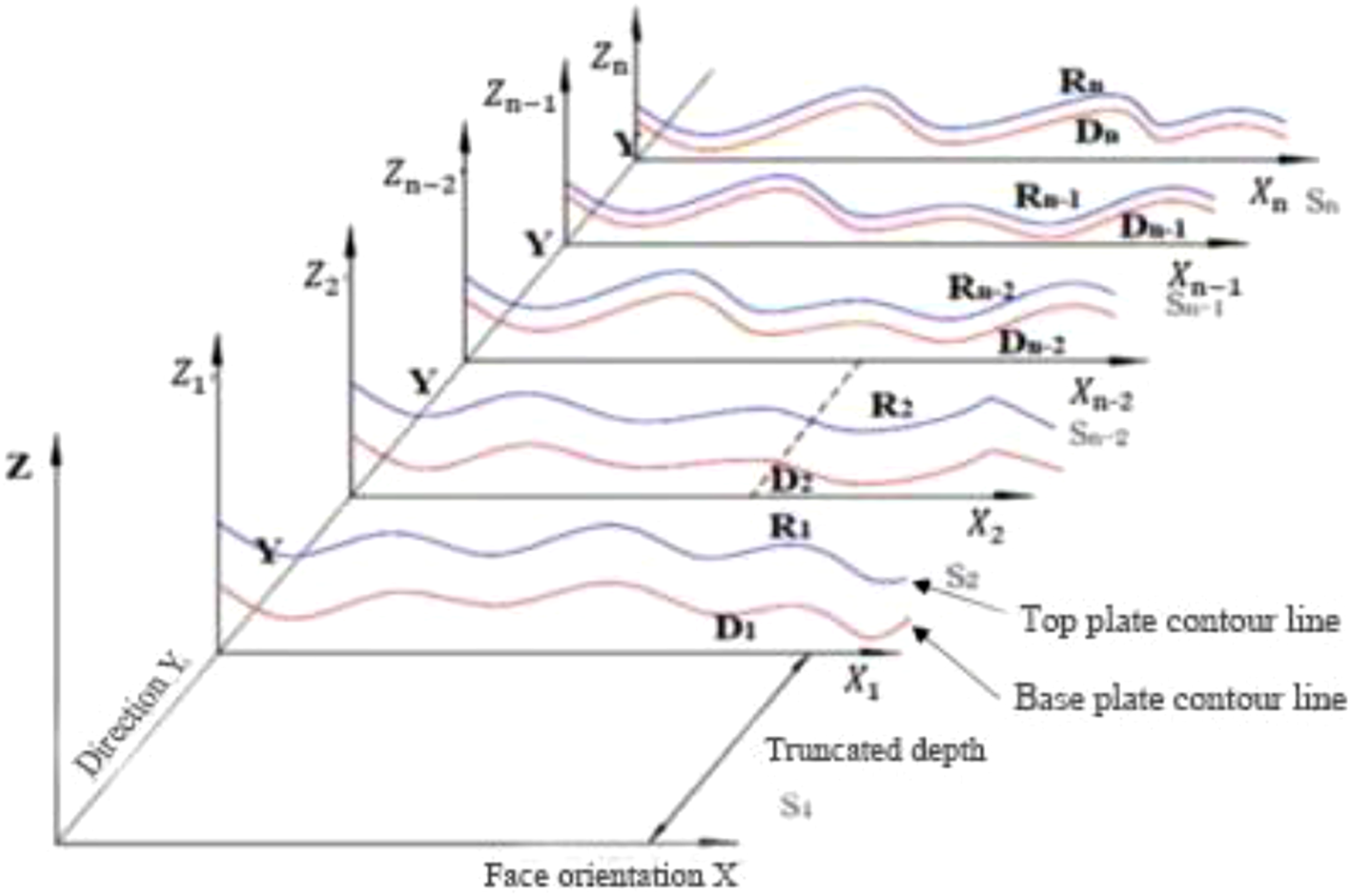
5. Cutting trajectory based on cubic B-spline algorithm
5.1. Shearer drum coordinate construction
In order to accurately describe the motion of the shearer in a certain spatial and temporal domain, it is necessary to select a suitable reference system to determine the corresponding coordinates. Judgement of whether the shearer is moving is based on the position change respect to the reference in the navigational coordinate system.
The body position of the shearer is deduced as described below. Set the origin of navigation coordinate system Schematic diagram of coal mining machine coordinate conversion.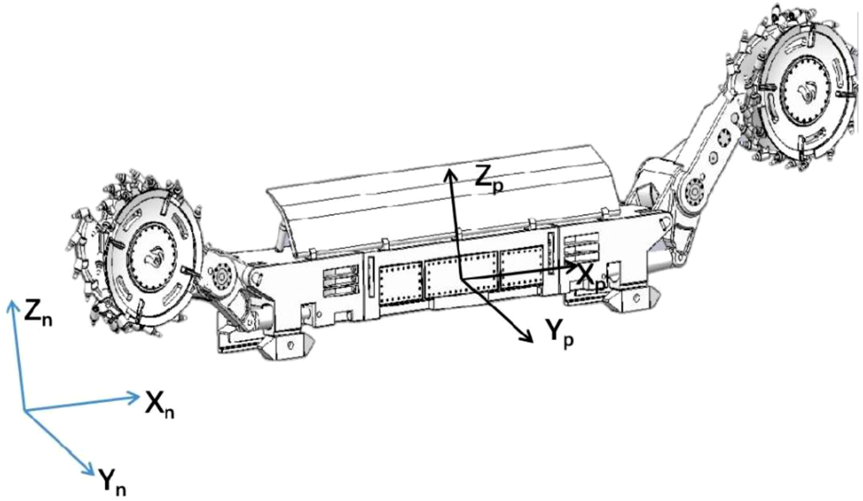
The inertial guidance system installed on the shearer can directly detect the position information of the shearer under the shearer system, and the position of the shearer under the navigation coordinate system is calculated by the cosine transformation of the three coordinate rotations, as shown in Figure 8. Schematic of coordinate system rotation.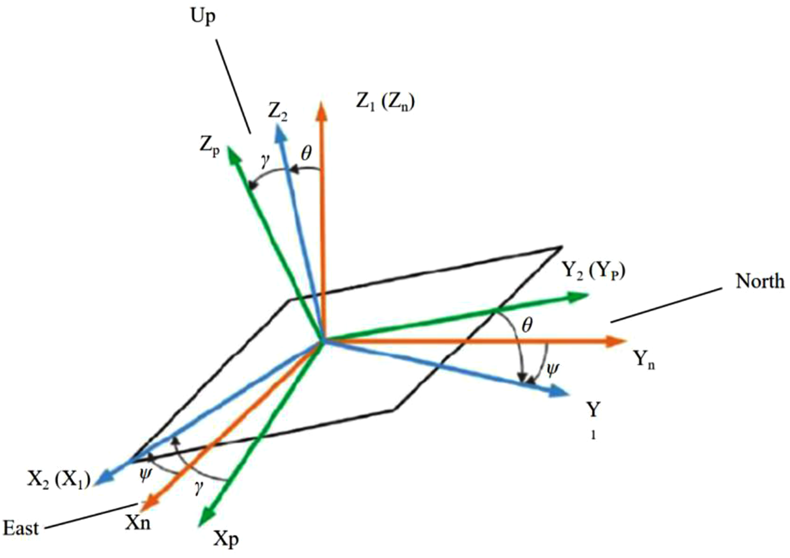
Determination of the shearer body position matrix based on the earth coordinate system and navigation coordinate system can be achived by:

The azimuthal projection equation for the shearer coordinates is:


The coordinate value of the shearer position under the shearer navigation coordinate system is:

Establish three coordinate systems denoted by Coordinate transformation diagram of rocker arm of coal shearer.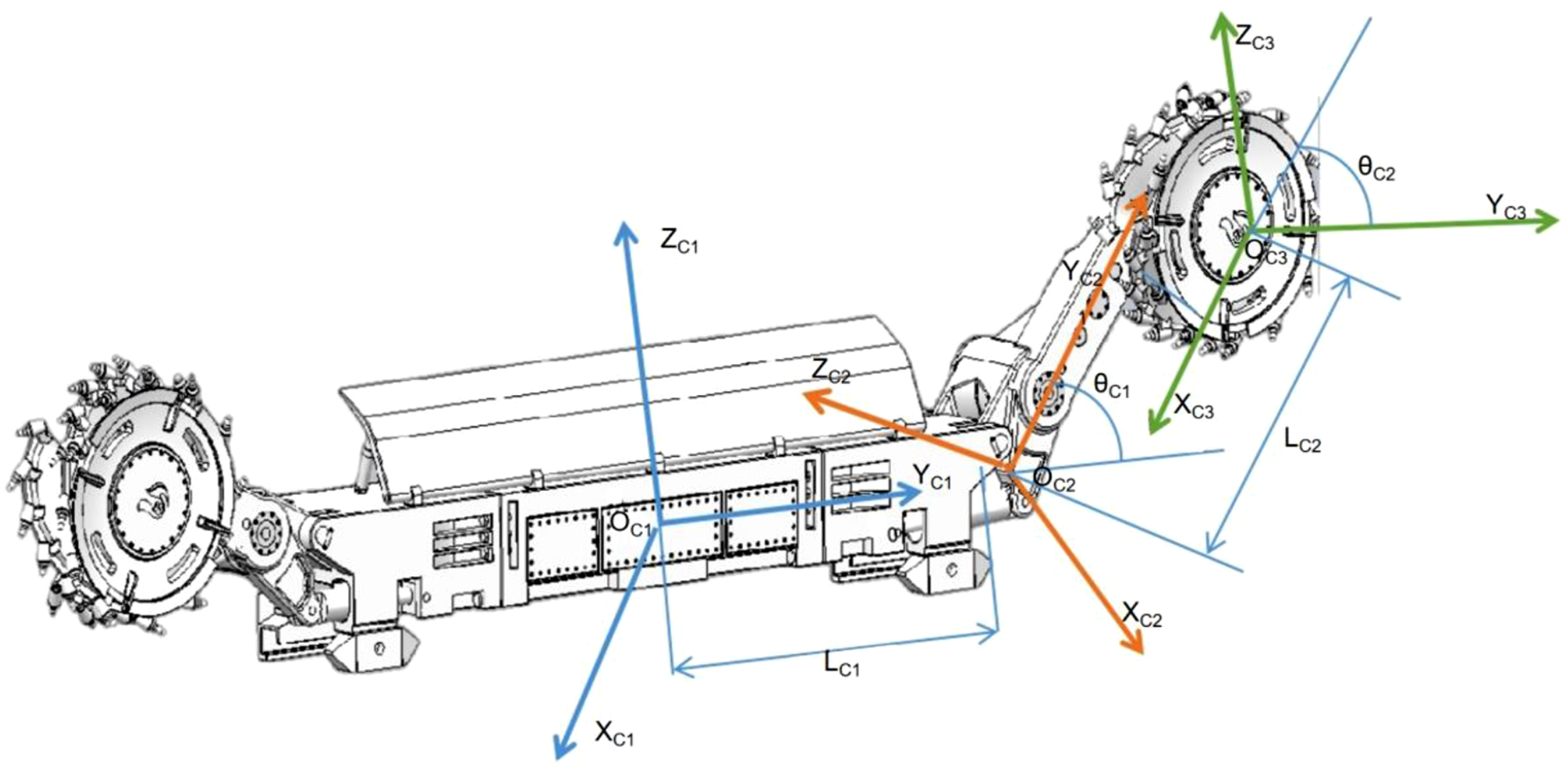
The D-H method is used to find out the position matrices of the right arm and drum of the shearer in the shearer coordinate system


Define the

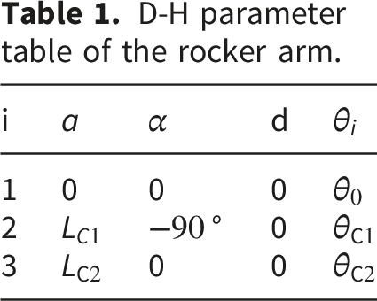
According to the D-H method, after knowing the transformation matrix
Position matrix

Position matrix

D-H parameter table of the rocker arm.
5.2. Cutting trajectory planning of the shearer drum
5.2.1. Real-time fitting algorithm of cubic B-spline curve
The real-time fitting algorithm of the cubic B-spline curve is determined by setting up boundary conditions and controlling the inputs to be the type-value points of the coal seam top-bottom line through the acquired coal seam top-bottom truncation trajectory data.
The three segments B-spline curve 



The slope of the curve is:
If the control points of the cubic B-spline curve is selected as the ideal roof and floor cutting trajectory points, the cutting trajectory curve obtained does not pass through all the control point, which cannot meet the accuracy requirements. Therefore, it is necessary to inverse the control points of the trajectory firstly, which is achieved by inputting the roof and floor cutting trajectory points as the type value points to ensure that the generated cubic B-spline curve passes through the trajectory points. For the given 

According to the method above there are
5.2.2. Generation of cutting trajectory curves
The profile curves of the roof and floor of the coal seam are obtained on the basis of the cubic B-spline fitting curve. Due to the drum diameter of the shearer is fixed, without changing the x, y-axis coordinate values, the z-axis coordinate values increase or decrease with the various sizes of the drum radius, the both drums cut trajectory curves can be get. In order to ensure that the cutting trajectory is smooth, the slope of the curve need to meet the conditions of continuity and no sudden changes, as shown in Figure 10. Slopes of the roof boundary curve.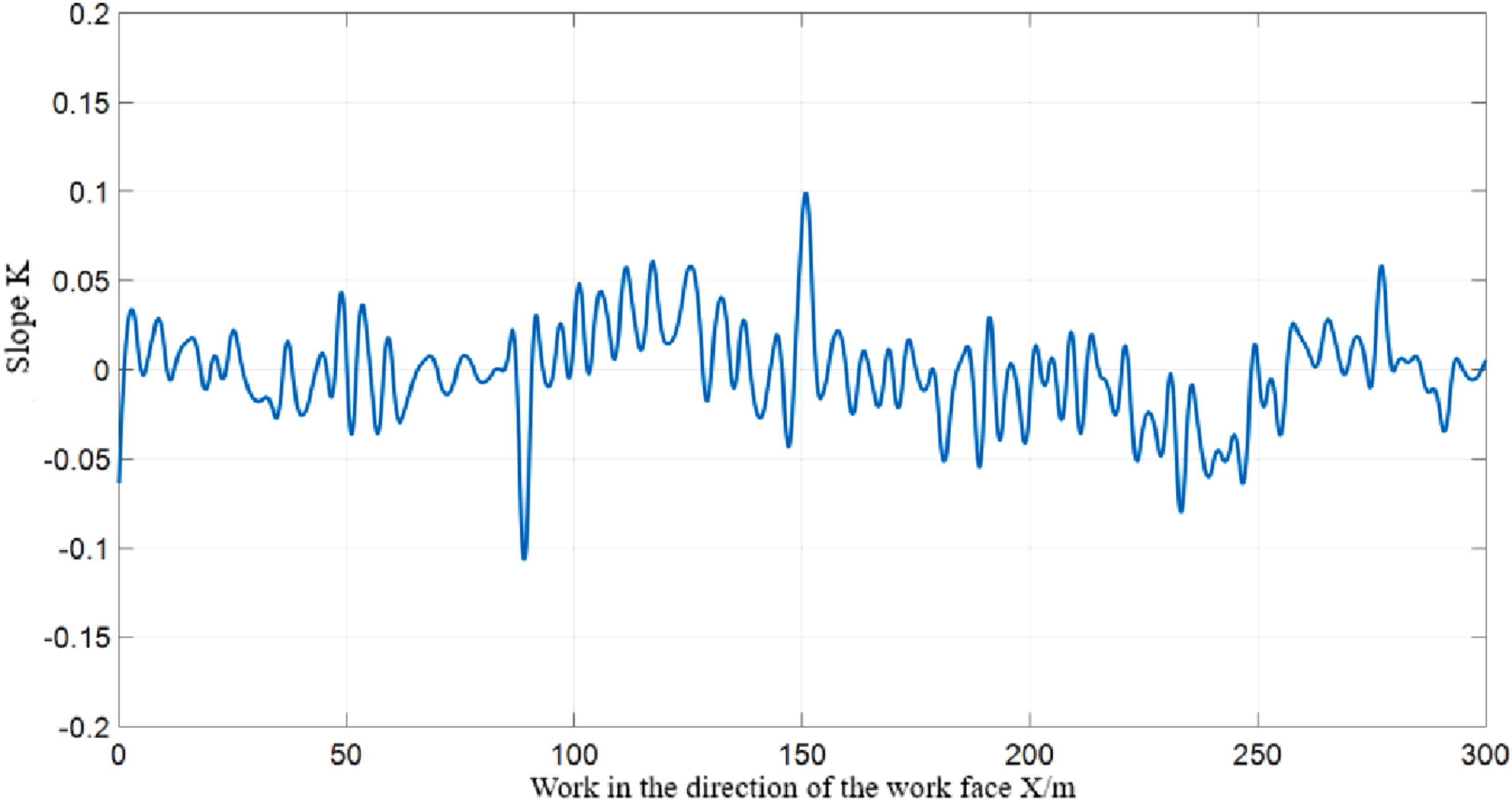
Figure 10 illustrates slopes of the coal seam roof boundary curve with various x values along the working face, which details the process of establishing control points of the curve. Figure 11 delineates the roof type-value points with black line and marks the control points with red triangles. For the roof boundary curve ranging in the 0-300m segment of the working face, a total of 150 type -value points, denoted as N, are selected. Following the principle that the number of control points is N + 2, we have 152 control points in total, and to identify the floor boundary curve control points the same principle does. Coal seam roof control points.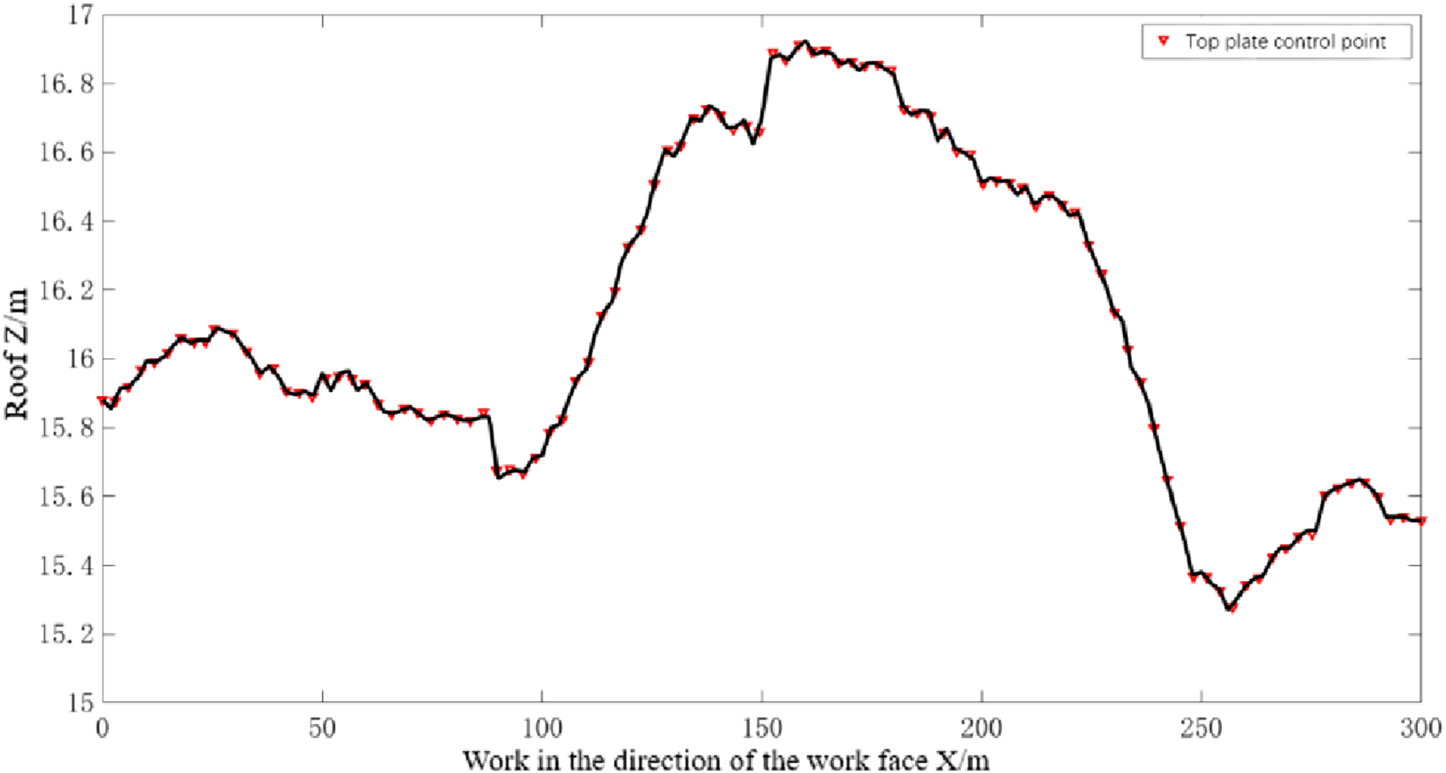
The algorithm of the process is outlined as follows:
Two sets of matrix equations are employed to calculate the control points for the B-spline curves in both x and y coordinates. The catch-up method is ingeniously utilized to simplify the time complexity involved in solving these tridiagonal matrices.
The Hadley-Judd method is then applied to ascertain the nodal vectors, which are instrumental in segmenting the B-spline curve. In this method, the x and y coordinates are unified under a single parameter, u. Each node within the nodal vectors defines the boundary of individual curve segments, with the elements of u arranged in a strictly increasing order, ensuring that no subsequent element is less than its predecessor.
The global variable is transformed into a local variable, t, facilitating the computation of the matrix that comprises the control points.
Finally, the x and y coordinate values of the cubic B-spline curve are derived.
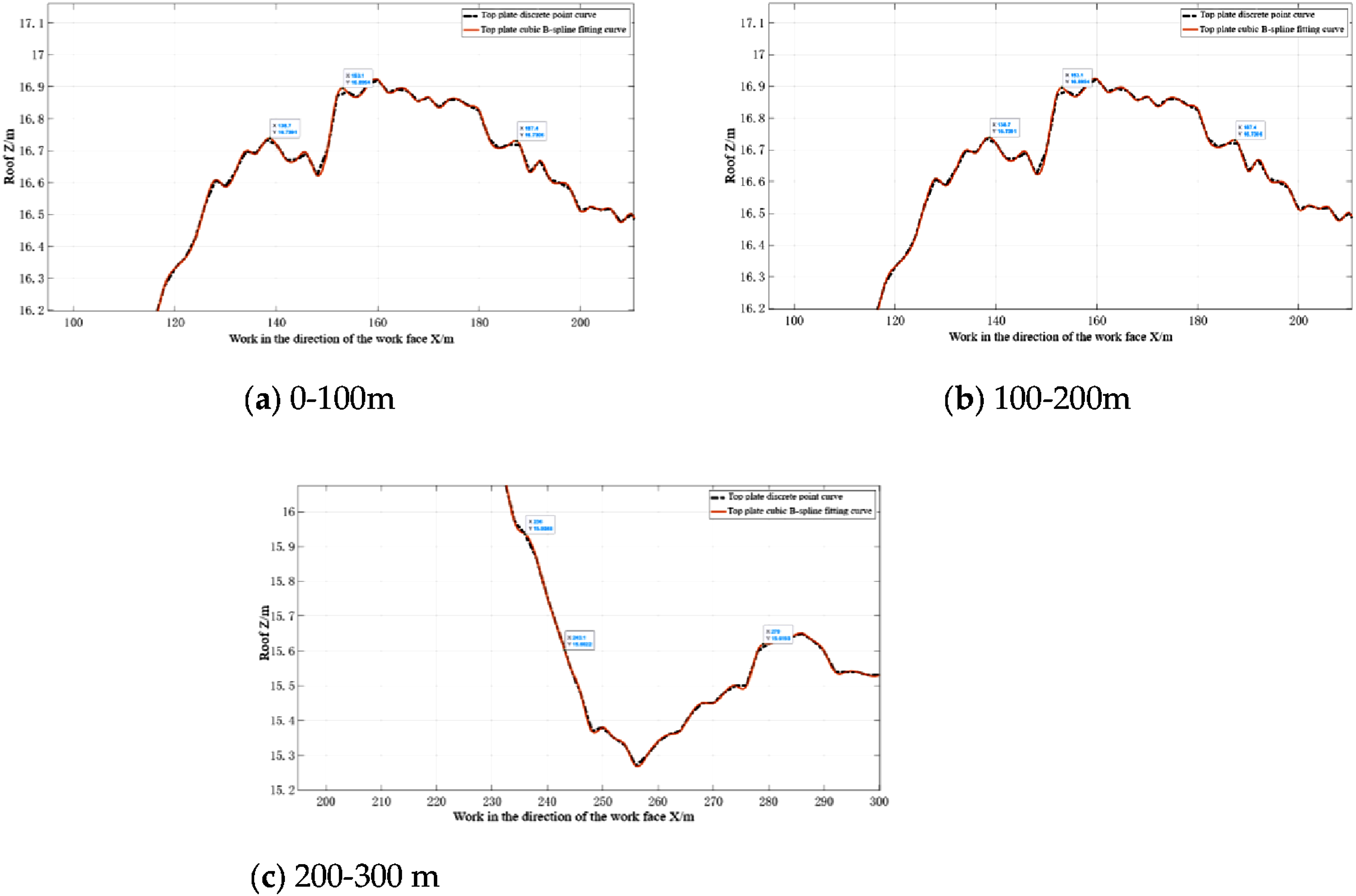
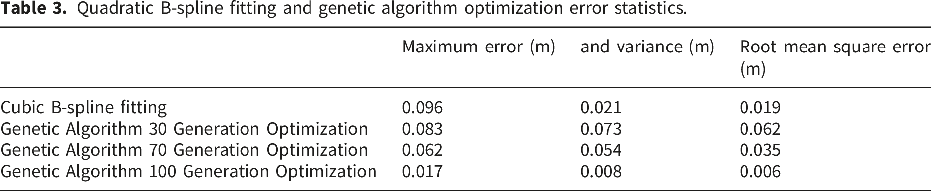
After inputting the roof and floor cutting trajectory points as the type value points to invert the control points, then the cubic B-spline fitting curves of the roof and floor of the coal seam passing through the control points are obtained, and the floor cutting trajectory curve has the same principle of generating the roof cutting trajectory curve. The results of the roof and floor controlling the discrete points along the working face from 0 to 300m are shown in Figure 12. The maximum error is 0.096m, and the variance is 0.021m, and the mean square deviation is 0.019m. The overall fit is close to the discrete point line, and it can generate a continuous smooth trajectory curve. The partial drawing of the curves is shown in Figure 13 (a), (b) and (c). The overall workflow follows a sequential pipeline of real-time model updating, boundary extraction, trajectory fitting, and genetic optimization, enabling adaptive and efficient trajectory planning for intelligent shearer operation. Roof boundary curve and its cubic B-spline fitting. Local magnifications of roof curve with cubic B-spline fitting. (a) 0-100m. (b) 100-200m. (c) 200-300 m.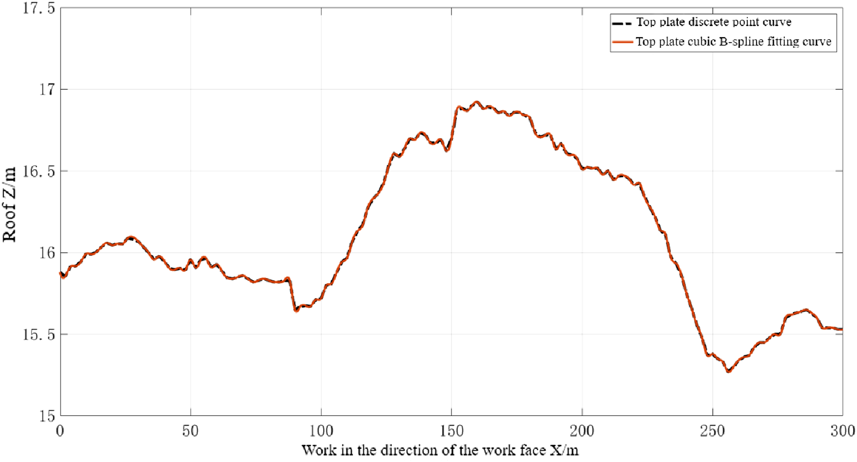
6. Optimization of cutting trajectory based on improved genetic algorithm
6.1. Optimization algorithm selection
The cubic B-spline algorithm is used to generate a smooth initial cutting trajectory from discrete roof/floor boundary points, providing a feasible initial solution. The genetic algorithm takes the fitted B-spline trajectory parameters as input to perform secondary constrained optimization, aiming to reduce fitting errors, restrain trajectory deviation, and prevent rock intrusion. The GA optimizes rather than replaces the B-spline fitting, forming a complete “initial fitting–constrained optimization” trajectory generation framework.
In order to determine the appropriate optimization algorithm, the data of 75-120m roof section was selected in the coal seam model to compare the experiment results by the BP, RBF, and genetic algorithms. To ensure a fair comparison among the BP, RBF, and genetic algorithms, the 75–120 m roof section was selected as a representative local segment of the working face, where the coal-seam boundary exhibits continuous fluctuation and the trajectory correction problem is sufficiently nontrivial. This segment is used to evaluate the local optimization capability of the algorithms under identical geometric constraints and initial trajectory conditions. The optimization comparison results were obtained as shown in Figure 14. Comparisons of three optimization algorithm.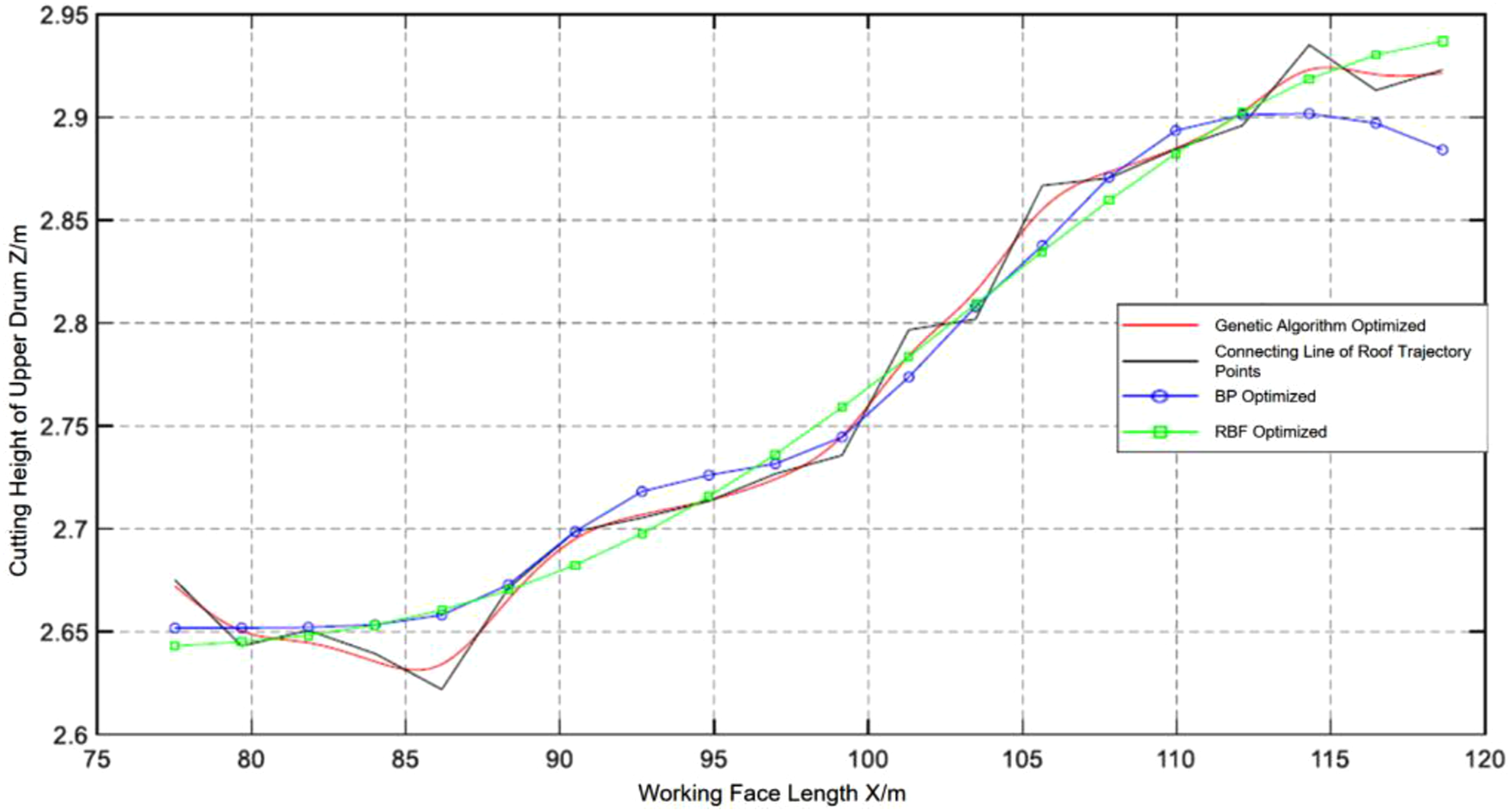
To enhance economic benefits by minimizing the gangue amount through reducing cutting into the roof and floor rock layers, the optimization of the cutting trajectory must take into account a multitude of factors. They include the characteristics of the rock layers in both the roof and floor, fluctuations of the coal seam, and the supportive effects of hydraulic supports. Such considerations are crucial for refining the trajectory to ensure a smoother fitting of the cutting trajectory and to diminish the discrepancy between the cutting path and the coal seam roof and boundaries.
Figure 14 presents a comparative analysis of the optimization errors for three algorithms of the roof trajectory. Among them, the genetic algorithm demonstrates the most precise results, with a maximum error of 0.032 meters and a mean square deviation of 0.023. In contrast, the Backpropagation (BP) neural network algorithm exhibits a maximum error of 0.064 meters and a mean square deviation of 0.036, while the Radial Basis Function (RBF) neural network algorithm shows a maximum error of 0.055 meters and a mean square deviation of 0.038. Based on these findings, the genetic algorithm is selected for its superior performance in trajectory optimization, which offers the lowest error rates and the highest coal recovery rates.
The parameters of the genetic algorithm were selected to balance convergence speed, search diversity, and computational burden in the trajectory optimization task. A moderate crossover probability was adopted to preserve useful genetic information while maintaining sufficient exploration capability, and a low mutation probability was used to avoid excessive disruption of high-quality individuals and to reduce the risk of unstable oscillation during evolution. The population size and the maximum number of generations were set empirically to ensure stable convergence within an acceptable computation time for real-time or near-real-time trajectory planning. In this study, these parameters are treated as engineering-oriented operating values that provide a practical compromise between optimization accuracy and algorithmic stability.
Genetic algorithm sets parameters.

6.2. Evaluation of genetic algorithm optimization
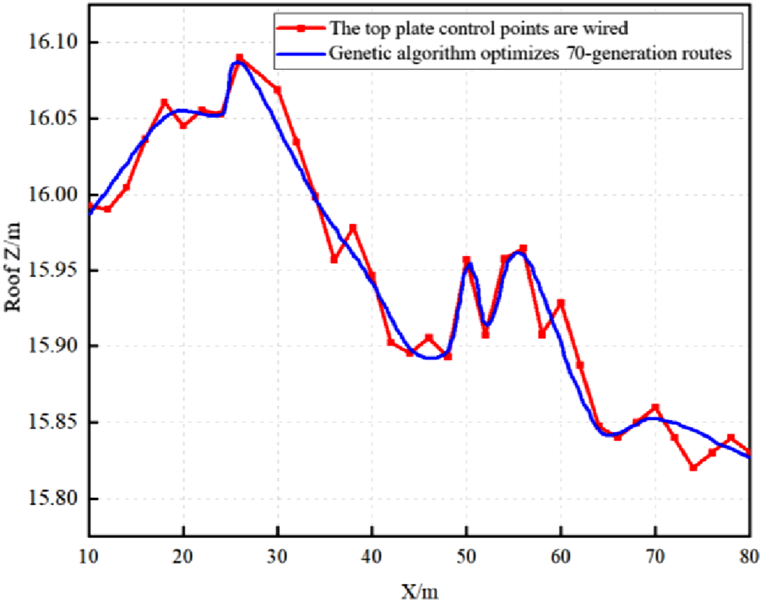
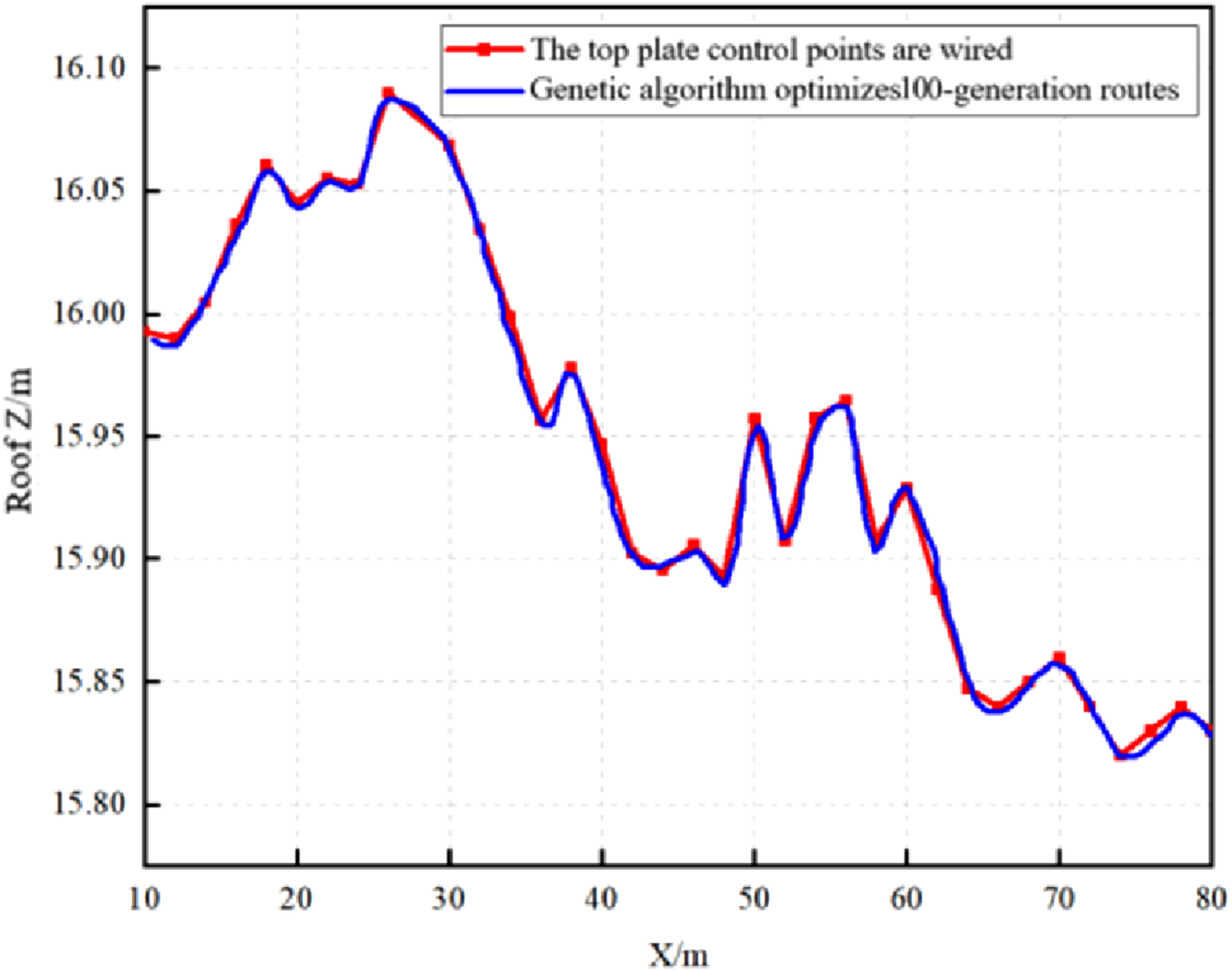
Through the cubic B-spline fitting algorithm on the roof and floor discrete points for control points, the roof and floor boundary lines are optimised to make it smooth and controllable. The input data for this optimization process are derived from the dynamically updated local coal seam model described in Section 1.2, ensuring that the trajectory planning adapts to the latest geological information. (comment5)The roof line points between 10-80m in the working face are selected for optimization, considering that the shearer generates the cutting trajectory in real time in the process of autonomous cutting. The evolutionary number of generations is too large which will lead to the computation time is too long. Therefore, when the number of generations is beyond to 100, the iteration is stopped. The optimized trajectory lines with evolutionary numbers are shown in Figures 15–17. Genetic 30 generation optimization route. Genetic 70 generation optimization route. Genetic 100 generation optimization route.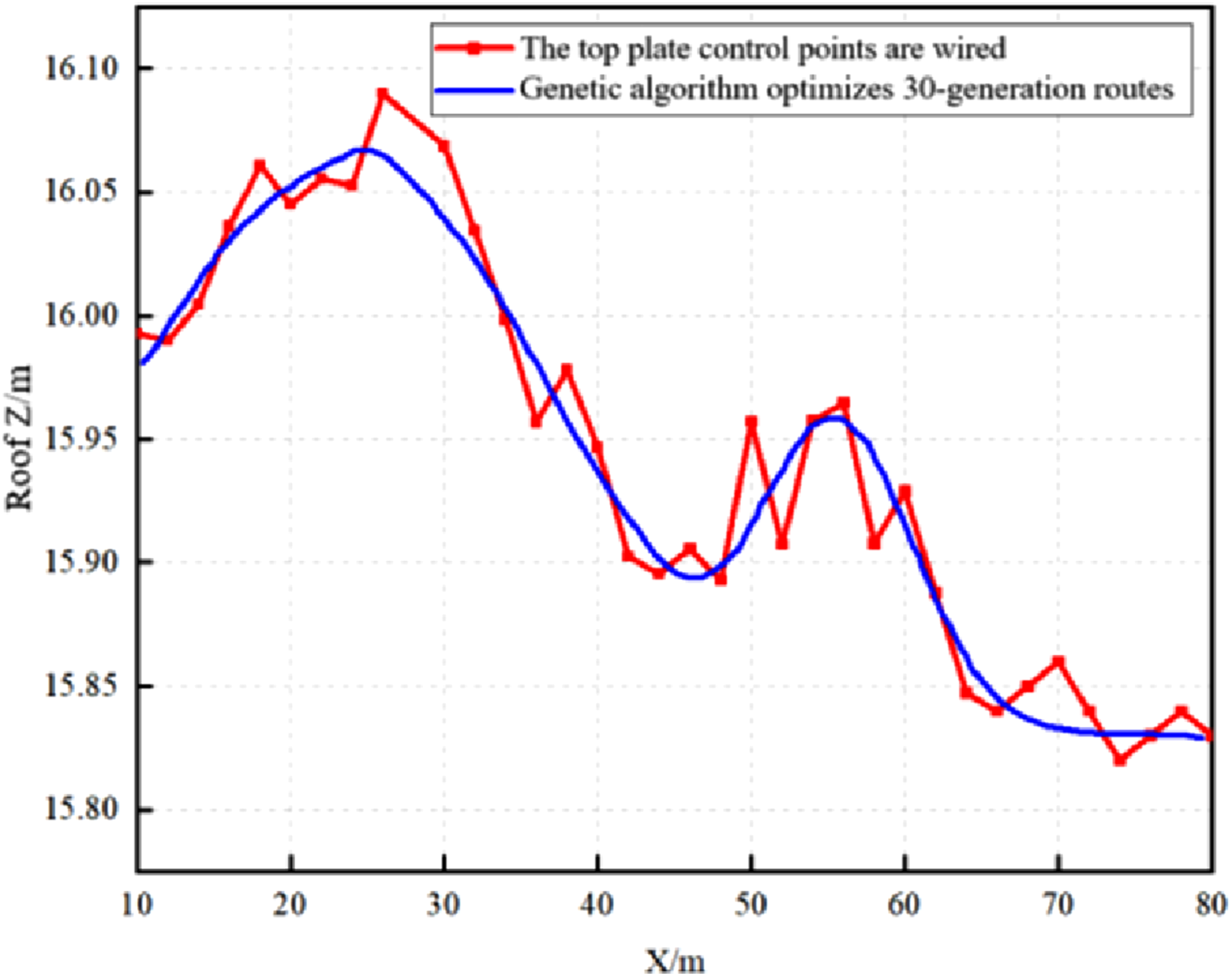
Quadratic B-spline fitting and genetic algorithm optimization error statistics.
The proposed method was implemented in C++ and executed in a single-threaded CPU environment on an Intel Core i7 eight-core processor with 16 GB of RAM. Under representative operating-condition data, the average runtime of cubic B-spline trajectory fitting was 42.6 ms, and the average runtime per genetic-algorithm iteration was 386 ms. These results suggest that the proposed method is computationally feasible for real-time or near-real-time generation of autonomous shearer cutting trajectories.
7. Conclusion
This study proposed an integrated framework for intelligent shearer cutting trajectory generation, incorporating real-time coal seam model updating, roof and floor boundary extraction, cubic B-spline trajectory fitting, and genetic algorithm optimization. By combining high-precision coal seam modeling with trajectory optimization techniques, the proposed method enables adaptive and accurate trajectory planning for autonomous shearer cutting. The results demonstrate that the framework can effectively improve trajectory accuracy while maintaining computational efficiency, providing technical support for intelligent navigation mining and autonomous operation of shearers. (1) A cyclic generation method for the coal seam working-face model based on the plane implicit function was developed, and an improved KNN algorithm was employed to extract the roof and floor boundary curves. The proposed method enables efficient generation of coal-seam boundary data and provides reliable geometric information for subsequent trajectory planning of the shearer drums. (2) Based on the extracted boundary information, a trajectory planning method integrating cubic B-spline fitting was established to generate smooth and continuous cutting trajectories. For the initial fitting results, the maximum error, variance, and root-mean-square error were 0.096 m, 0.021 m, and 0.019 m, respectively, demonstrating that the method can effectively represent the geometric characteristics of the coal seam boundaries while ensuring trajectory continuity. (3) A genetic algorithm was further introduced to optimize the initial cutting trajectory. After 100 generations of optimization, the maximum trajectory error was reduced to 0.017 m, the variance decreased to 0.008 m, and the root-mean-square error decreased to 0.006 m. Compared with the original cubic B-spline fitting results, the root-mean-square error was reduced by approximately 68.42%. Furthermore, the average runtime of the optimization process was 386 ms, indicating that the proposed method satisfies the real-time requirements of intelligent shearer autonomous cutting.
8. Limitations and future research directions
8.1. Limitations of this study
The present study establishes a complete trajectory planning framework for intelligent shearer cutting, including real-time coal seam model updating, roof and floor boundary extraction, cubic B-spline fitting, and genetic algorithm optimization. However, the validation is still carried out at the level of model construction and representative local-segment experiments, rather than on a full-scale underground longwall system. All experiments are conducted under ideal laboratory conditions without considering underground disturbance factors such as coal dust, electromagnetic interference, and sensor drift, which may reduce the accuracy of real-time model updating and coal-rock interface detection. In addition, the current evaluation mainly focuses on geometric fitting accuracy and computation time. The effects of the proposed method on actual coal recovery, gangue reduction, and long-term operational stability in continuous production have not yet been quantitatively assessed.
8.2. Future research directions
Future research will extend the proposed framework to full-scale shearer operations and evaluate its performance under real mining conditions. In particular, more field data from heterogeneous coal seams should be introduced to test the robustness of the real-time updating mechanism and the boundary extraction algorithm under stronger geological uncertainty. Further work will also focus on improving the adaptability of the trajectory optimization module so that it can better respond to abrupt seam changes and equipment-state disturbances during continuous cutting. On the implementation side, the computational efficiency and stability of the method should be verified on more practical embedded or industrial control platforms. In addition, future studies can further examine the influence of the optimized cutting trajectory on production efficiency and resource recovery, so as to provide stronger support for practical engineering application.
Footnotes
Acknowledgements
The authors sincerely appreciate the constructive comments and valuable suggestions from the editor and reviewers, which have significantly enhanced the quality of this manuscript. The authors also would like to thank the engineering team of the relevant coal mine for providing the geological data and on-site working conditions, which laid a solid foundation for the smooth progress of this research.

Author Contributions
Conceptualization, X.H. and R.W.; Methodology, X.H. and Z.W.; Software, R.W. and Z.W.; Validation, C.H., Bo Li and Bin Liu; Formal analysis, J.L. and G.G.; Investigation, C.H., Bo Li. and Bin Liu.; Resources, Y.L. and B.Z.; Data curation, Y.L. and B.Z., Writing—original draft, R.W.; Writing—review & editing, X.H. and Z.W. All authors have read and agreed to the published version of the manuscript.
Funding
The authors disclosed receipt of the following financial support for the research, authorship, and/or publication of this article: This work was supported by the Key Research and Development Program of Shaanxi Province (grant number: 2024CY2GJHX49) and the Innovative Research Group Project of the National Natural Science Foundation of China (grant number: 52121003).
Declaration of conflicting interests
The authors declared no potential conflicts of interest with respect to the research, authorship, and/or publication of this article.
Data Availability Statement
The data that support the findings of this study are available from the corresponding author upon reasonable request. The coal seam geological data and experimental trajectory data are not publicly available due to restrictions related to engineering confidentiality and mine site management regulations.