






Abstract
The dynamic positioning simulation of an actual drill ship under a normal and faulty condition is proposed using MATLAB™ and Simulink™ software. The proposed simulation model provides a means to control a non-linear and coupled OD21 drill ship under different external perturbations, such as wind, wave, current and thruster failure during the design stage. A proportional–integral–derivative (PID) controller for the dynamic positioning ship system was designed and validated with experimental results from a sea trial. Through simulation, the proposed PID control and thrust allocation method are able to maintain the desired heading angle under various test conditions, such as drilling, standby and thruster failure.
1. Introduction
Mathematical modeling and simulation involve many fields of engineering. They are essentially multi-disciplinary in their applications and have increased in presence within industries and institutions. The multi-disciplinary control problem of dynamic positioning systems for ships has been widely studied.1–4 The dynamic positioning of ships is required in many offshore oil field operations, such as drilling and pipe-laying. The control problem involves finding a controller to stabilize both the position and orientation of the ship to desired constant values. The success of a dynamically positioned ship depends on its capability for accurate and reliable control, subject to environmental disturbances and faulty thrusters.
In this paper, the dynamic positioning problem for an actual drill ship, named OD21 (Ocean Drilling in the 21st Century), for deep-water scientific ocean drilling is considered. In the drill ship design, it is equipped with seven thrusters located at a distance from the center line in order to give the required motions. This gives sufficient actuators to control the surge, sway and yaw motions of the ship. Besides having these actuator’s redundancies, robustness can be obtained by changing the control law when one actuator failure is detected. This represents a software solution to fault handling in the event of actuator failure, 5 which is commonly known as a thrust allocation system. The thrust allocation system implements a function that maps the desired control forces generated by the vehicle motion controller into the thrusts required on different thrusters during the dynamic positioning.
However, the dynamic positioning control of the drill ship and the presence of the thrust allocation system are feasible if computer simulation can be performed on the mathematical model. This helps to verify and compare the control system design with the sea trial results that are often exacerbated by the environmental disturbances and inherent non-linear ship dynamics. Moreover, one of the major challenges in creating a computer ship model is the quantification of the forces acting on the ship. The forces must be correctly represented and validated with experimental results; otherwise, there is a risk of designing a controller based on erroneous information. Hence, the OD21 drill ship model used in this paper was verified from both the experiment and sea trial tests. In addition, software such as MATLAB™ and Simulink™ are used to simulate the OD21 drill ship (or other types of ships) in the best-to-knowledge simulation environment due to the wind, wave and current forces during both the normal and faulty thruster conditions. There is some commercial software 6 for dynamic positioning; however, they can be quite expensive for initial evaluation. Similar software, called the Marine Systems Simulator (MSS) and developed by Fossen 7 and his team, is commonly used by researchers to simulate marine vessels. But the dynamic positioning of the drill ship model is not available in the software.
This paper is organized as follows: The overall view of the OD21 drill ship is addressed in Section 2. In Section 3, the non-linear drill ship model is presented. In Section 4, the simulation models for the ship and thrusts allocation system are described. This is followed by the model verification and dynamic positioning tests in Section 5. Finally, conclusions are shown in Section 6.
2. Overview of OD21 drill ship
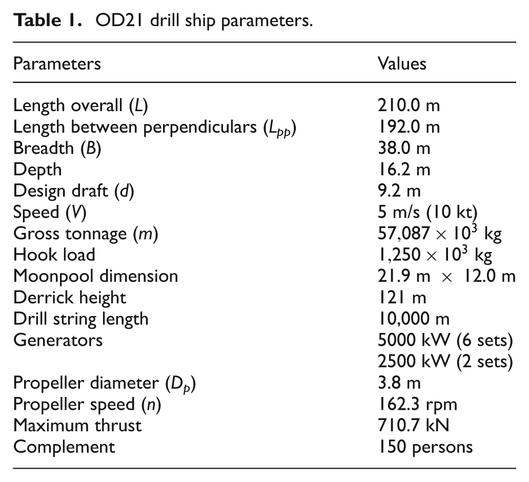
This section describes the main features of the OD21 drill ship. The OD21 is designed to apply state-of-the-art drilling technologies that comply with the scientific deep-water drilling requirements. Detailed model descriptions of the OD21 drill ship are available in the literature.8,9Table 1 highlights the principal parameters of the OD21 drill ship used in the modeling. The basic design of the OD21 drill ship was started in 1999, under the Japan Marine Science and Technology Center, Mitsui Engineering and Shipbuilding Co., Ltd and Mitsubishi Heavy Industries Ltd. The construction of the vessel were started in 2001 and completed in early 2004. The OD21 drill ship testing was conducted at basins of the Akishima Laboratories (Mitsui Zosen) Inc. in Tokyo, Japan. However, more studies are still required to understand the dynamic positioning system of the ship. Hence in this paper, the dynamic positioning system of the drill ship is studied.
OD21 drill ship parameters.
3. Non-linear ship model for dynamic simulation
For dynamic position purposes, it is necessary to keep a vessel’s position within the required distance from the decided position during the drilling operations. As the OD21 drill ship aims to perform deep-water scientific ocean drilling up to 4000 m water depth by using riser drilling and 7000 m water depth using riserless drilling, dynamic positioning is the only solution for the position keeping. Prior to that, ship’s hydrodynamic model data are required. In order to obtain the hydrodynamic model data, the wind tunnel, wave drift, current, yaw-rotating and thruster interaction tests had been conducted at basins of the Akishima Laboratories.8,9
In this section, the dynamic model of the OD21 drill ship is developed based on the model, as shown in Figure 1. The mathematical model for the dynamic positioning simulations is represented based on coupled equations of surge, sway and yaw.

Model for the dynamic positioning control test (1:55 scale model).
3.1. Dynamics equations of the drill ship
As a ship moves in the horizontal plane with forward (or surge) speed



where the terms with subscript w, D, H and T represent the wind forces, wave drift forces, hull forces and thruster forces, respectively. The moment of inertia is approximated as



where the mass of the drill ship
3.2. Wind forces
The wind forces



where the air density
3.3. Wave drift forces
The wave drift forces



where
3.4. Current forces
The current tests8,9 were performed with and without the ducts of the azimuth thrusters at the design draft using the scale models similar to the wave drift force tests. As the thrust used in the dynamic simulations includes the drag of the ducts, the results without the ducts are applicable in the dynamic simulations. On the other hand, the results with the ducts are conservatively applied to the static simulations. The non-dimensional forces and moment are expressed as functions of the drift angle



where
3.5. Hydrodynamics forces
The hydrodynamic forces acting on the hull consists of three terms:



The terms with subscript H1 represent the hull forces due to pure drifting motion only, namely the current forces. The terms with subscripts H2 and H3 represent the hull forces, respectively due to pure turning motion and the coupling effect between pure drifting and a turning motion. These forces were obtained from the yaw-rotating tests,8,9 in which the scale model was towed at a constant speed while rotating around the vertical axis through the mid ship with a constant yaw angular velocity. It was found from the yaw-rotating tests that the mathematical model for the hull forces is



where the surge velocity relative to water




where

3.6. Thruster forces
The forces and moment generated from the six azimuth thrusters can be expressed by



The thruster–current interaction tests were performed in open water for the individual azimuth thruster without the hull. The thruster–current interference effects, for example, the non-dimensional longitudinal force
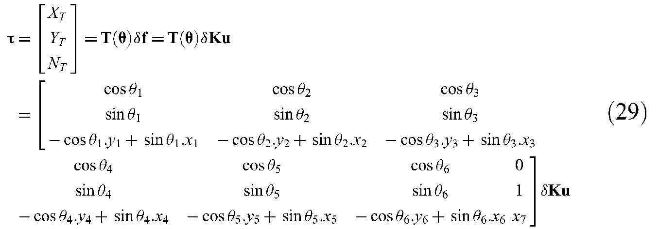
where the thrust configuration matrix

where
The thruster configuration on the drill ship can be seen in Figure 2. As shown in the thrust configuration, the bow thruster contributes to the sway and yaw motion only, and hence it consists only of

Thruster configuration on the ship.
However, Equation (29) is non-linear in the controls


By considering the inputs where the azimuth controls are modeled:


By using the extended thrust vector, Equation (29) can be rewritten as
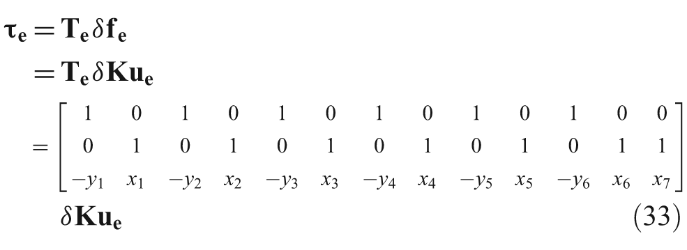
where
Notice that

3.7 Thrust allocation optimization
In order to determine the optimized control forces for each thruster, the following least-square optimization
1
method is used. Assume that the vector

subject to

where
The solution of the above problem using Lagrange multipliers 1 is written as

where

is recognized as the generalized inverse. For the case of
Thus, expression (38) reduces to the Moore–Penrose pseudo-inverse:

Since

4. Simulation model for drill ship dynamics and the thrust allocation system
In this section, the simulation model of the drill ship is shown. The external disturbances from Section 3 are modeled as forces acting on the drill ship during the dynamic positioning. To overcome these disturbances, a proportional–integral–derivative (PID) controller is then designed. In addition, the thrust allocation system is used to counter the effect of thruster failure during the dynamic positioning.
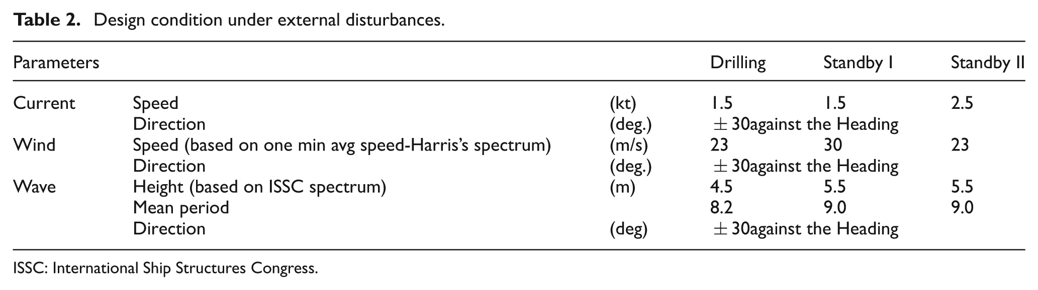
To study the robustness of the drill ship, changes are made on the external disturbances. The changes are tabulated into several test conditions, as shown in Table 2. The model is executed many times to “simulate” the impacts of these changes on the ship’s velocities and positions. In the drilling and standby tests, the model was controlled to maintain a desired heading (that is, –50 degrees) and position-keeping accuracy under these conditions. In the drilling operation, it is required to make the deviation from the desired position as small as possible. For the position-keeping accuracy, it is specified using 2σ p ,8,9 which is two times the standard deviation of the ship’s deviation from the target point. This value refers to the position’s spread around the target point. In this case, the ship is required to control her position and heading of less than 2σ p as follows: 15 m (in drilling) and 30 m (in standby I and II) for 1000 m in water depth.
Design condition under external disturbances.
ISSC: International Ship Structures Congress.
A systematic step of modeling and simulating the drill ship model is shown below. Firstly, the differential equations in (1)–(3) of the drill ship are modeled using Simulink™. Most of the parameters used in the simulation are obtained from the experimental results.8,9 The dynamic model includes the effects of the wind, wave, ocean current and thruster forces (see the left-hand side of Figure 3) acting on the drill ship model. The rotational matrix block diagram on the right-hand side of the diagram enables the transformation of the linear speed motions to the ship’s heading angle. The numerical solution of the model is solved using the ODE45 solver. The solver options used in this paper are configured as a variable-step type with a relative tolerance of 0.001. The simulation time of 200 s is used.

Dynamic model of the OD21 drill ship.
With the dynamics equations obtained, the PID controller is used to control the position of the drill ship during the dynamic positioning. The control signal that adds to the optimized or extended thrust forces in (33) can be written as

where
The PID controller is modeled as seen in Figure 4. In the model, the feedback path of the control loop can be disconnected for open-loop (without the PID controller) simulation. The error signal

Overall simulation model of the OD21 drill ship.
surge direction:
sway direction:
yaw direction:
The models used in the waves and wind forces are the Pierson–Markowitz 1 and Harris’s spectrum, 1 respectively. In these models, the resulting outputs are made dimensional by multiplying the force data by the force coefficients. As shown in Figure 5, the wind model is modeled using Equations (7)–(9). As the forces are a function of the wind direction and speed, a lookup table is used to model the actual non-dimensional data for different wind direction.

Wind model for simulation.
The wave drift model (see Figure 6) is simulated using Equations (10)–(12). The lookup tables are also used to model the actual non-dimensional data obtained from the model test. In this case, the primary input to the lookup tables is the wave direction. The significant wave height was obtained through the experiment. As shown in the Simulink™ model, two models are selected through a manual switch. The outputs from the two models simply provide the significance wave height for the computation of the wave drift forces. The first model 12 gives a different wave height based on the sea state or condition. The second model provides the actual wave height8,9 due to the wave direction acting on the drill ship. A similar method can be applied to the current model, as shown in Figure 7. The current model is obtained using Equations (13)–(15). The main inputs to the lookup tables are the current direction and speed acting on the drill ship during maneuvering.

Wave drift model for simulation.

Current model for simulation.
The hydrodynamic damping model (see Figure 8) for the symmetrical ship is determined using Equations (22)–(25). The instantaneous speed of the drill ship is obtained by solving the resultant speed in the surge and sway velocity. The surge force is mainly dominated by the current force, while the remaining current forces are computed from (22)–(25).

Damping model for simulation.
The azimuth thruster model is modeled as shown in Figure 9. The thruster–hull interference coefficients

Azimuth thruster and hull interaction model for simulation.
The optimization problem in the thrust allocation optimization aims at producing the demanded generalized forces, while at the same time minimizing the use of control effort (that is, the power). For example, in the case of an actuator failure, the remaining actuators are reconfigured by the control allocation system without having to change the motion controller structure. The control allocation function does not have a close form solution; instead, the values of the actuator commands are obtained by solving an optimization problem at each sampling period of the control loop. In this paper, the Moore–Penrose pseudo-inverse
1

Thrust optimization model for simulation.
5. Model verification and dynamic positioning tests
In this section, the validity of the closed-loop model used for the dynamic positioning of the ship is verified by the sea trial experiment. It is followed by simulating the drill ship model in various conditions, including the condition of a thruster (azimuth or bow type) that failed during the drilling and standby I and II conditions.
As the sea trial results are based on the actual system with the PID control, the closed-loop model of the drill ship is validated. The time histories and trajectory under the most serious external disturbances at the sea trials can be seen in references 9 and 10. In this case, 2σ p (that is, two times the standard deviation of the vessel’s deviation from the target point) comparison is used. From the sea trial result, it was around 2.2 m for the desired heading angle of −50 degrees.
The validity of the drill ship model is compared with the above-mentioned sea trial results. The results of numerical simulation under the same conditions are shown in Figure 11. As compared to the actual data 9,10, 2σ p is around 1.64 m, which is approximately 25% less than the actual results. This error may be due to the approximation in the disturbances caused by the coupling effect between the pure drifting and turning motion, and the PID controller gains used in the simulation. However, the heading and the thrust match the response of the actual sea trial.

Time histories and trajectory of the drill ship – simulated.
The robustness of the validated drill ship under the test conditions in Table 2 was tested. In the drilling and standby tests, the model was controlled to maintain the same heading angle (that is, –50 degrees) under the same conditions. However, the PID parameters used in the sea trial need to be altered and tuned by the Simulink™ Design Optimization toolbox in order to cope with the different conditions arising due to the wave, wind and current forces.
The simulated ship trajectories for the drilling and standby I and II conditions are given in Figure 12. As shown in the trajectories, the ship is able to maintain the heading position within the deviation of 15 m (drilling) and 30 m (standby). As seen in Figure 12, the controller corrects the heading error caused by the external disturbances. Despite these disturbances, the response manages to settle to the desired steady-state value at around 10 s. Table 3 gives the summary of the 2σ p position simulated in the various conditions, including the condition of the thruster (azimuth or bow type) that failed during the drilling and standby I and II conditions.

Position response with and without a faulty thruster in drilling and standby conditions.
Comparisons between different test conditions.
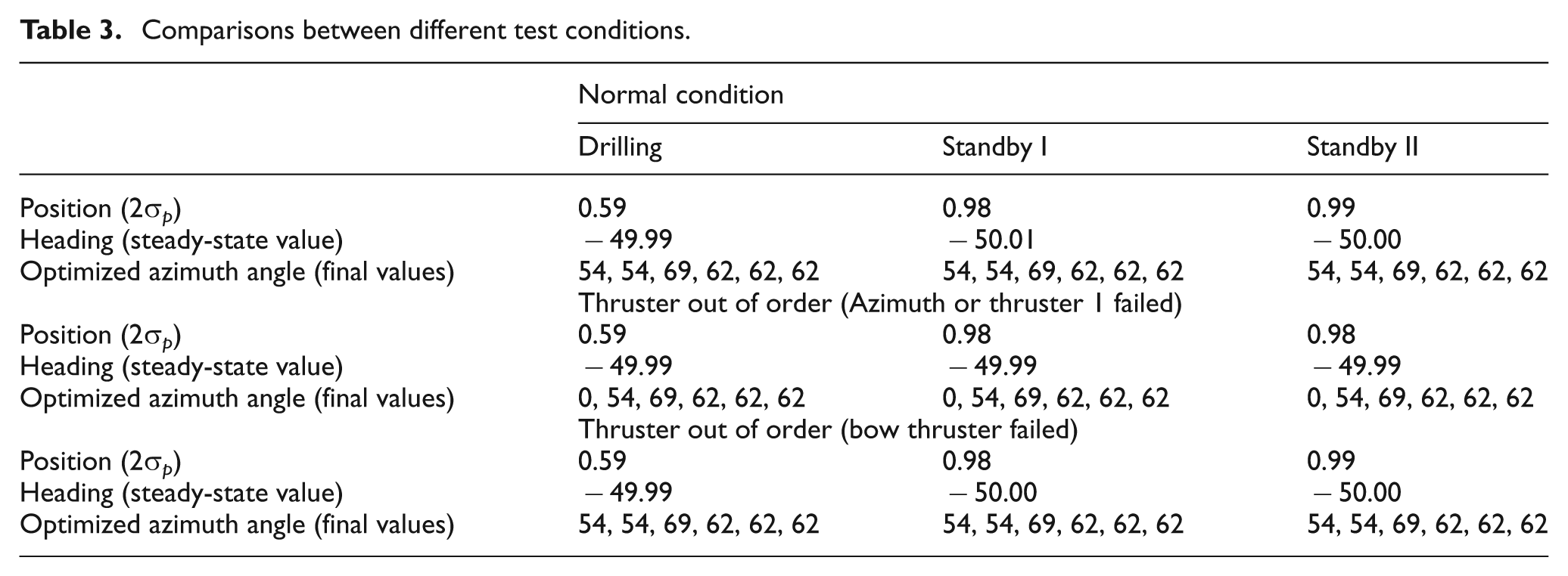
In summary, the test results show that the vessel was able to maintain her heading and position with sufficient accuracy, namely within the allowable excursion, even in the standby condition. As observed in the simulation results, the results of 2σ p are a little lower than the previous sea trial result due to the coupling effect between the pure drifting and turning motion, and also the PID gains used in the simulation. However, it is observed that the control system used in the dynamic positioning is quite robust to maintain the ship’s heading under the external disturbances. In addition, Table 3 shows the effect of sudden failure of one thruster during the dynamic positioning test. The results show that the proposed thrust allocation system on the OD21 drill ship is capable of handling the thruster’s failure without affecting the heading position. The positioning accuracy during the drilling and standby conditions is not affected, as shown in Figure 12. Hence, the dynamic positioning control system can work satisfactorily under these conditions, and a similar control system method can be applied to the full-scale drill ship.
6. Conclusions
The dynamic modeling, control and simulation of the OD21 drill ship using MATLAB™ and Simulink™ are proposed. In addition, dependent on experienced engineers in designing the dynamic positioning for the drill ship, the proposed simulation model provides a tool to verify the operational and design readiness of the drill ship under different wind, wave and current conditions before production. The simulation model is particularly useful, as the ship has to operate in a harsh weather environment that is inherently non-linear and coupled. The validity of the simulation model for the dynamic positioning of the drill ship was verified by the sea trial experiments. With a small standard deviation observed in the positioning data, the PID controller for dynamic positioning of the drill ship is quite robust against the external disturbances caused by the various wind, wave and current effects. In addition, the effect of sudden failure of one azimuth or bow thruster during the dynamic positioning test has shown to have no effect on the continuous operation or heading position of the drill ship.
As for the future works, more advanced controllers, such as H-Infinity control, fuzzy logic control and even the PID gain-scheduling technique, can be used for more severe and unforeseen environmental disturbances. The fault detection and control algorithm, using knowledge-based analytical models, and the analysis of the frequency spectrum can be used to detect and correct any thruster fault during the dynamic positioning.
Footnotes
Acknowledgements
The author would like to express his thanks to Newcastle University for providing great support during this project.
Funding
This research received a students’ project grant from the school of marine science and technology at Newcastle University.