
Abstract
For rigorously safe aviation, it is of great significance to conduct an analysis of the current and new operations, providing a global perspective of the scenario dynamics and a better understanding of the potential collision occurrence for risk assessment. The objective of this study is to consider a number of the difficulties that are involved when establishing a validation of the Traffic Alert and Collision Avoidance System (TCAS), which constitutes the last resort for reducing the risk of near mid-air collisions between aircraft in a multithread scenario, and to analyze the TCAS logic using a causal model. In this paper, the causal model that is specified in the Colored Petri Net (CPN) formalism is employed as a key approach to analyze quantitatively the state space of a congested traffic scenario in which the events could transform a conflict into a potential collision. It offers a rigorous tool not only for TCAS validation but also for the analysis of a wide range of properties of the TCAS behavior. This CPN model assumes unrestrained initial positions and TCAS II-equipped aircraft; it is demonstrated to be extremely effective for generating all possible future TCAS failure end-states from the current locations, and the Interactive Collision Avoidance Simulator EuroControl simulator is used to illustrate the collision process of a three-aircraft scenario.
Keywords
1. Introduction
A series of mid-air collisions over a period of 30 years (1956–1986) motivated the US Federal Aviation Administration (FAA) to launch the development of an effective collision avoidance (CA) system that would act as a last resort when there is a failure in air traffic controller (ATC)-provided separation services. 1 In the international scope, this system is known as the Traffic Alert and Collision Avoidance System (TCAS). TCAS was developed through comprehensive analyses and abundant flight evaluations, and this system has been demonstrated to play a successful role in reducing the risk of mid-air collisions between aircraft. 2
The main functions of TCAS are to communicate the detected threat to the pilot and to assist in resolving the threat by recommending an avoidance maneuver. Normally, TCAS, as an alert system, operates quietly in the background most of the time. When the TCAS logic determines that action is needed, TCAS interrupts the flight crew to bring the threat to their attention. 3
Until now, TCAS I and its improved version, TCAS II, have been defined and approved by the International Civil Aviation Organization (ICAO), and they differ primarily in their alerting capability. TCAS I provides traffic advisories (TAs) to assist the pilot in the visual acquisition of intruder aircraft, whereas TCAS II provides both TAs and resolution advisories (RAs); in other words, recommended escape maneuvers. 3 TCAS II version 7.1 is the current in-use system: it was designed mainly for encounters between two aircraft, and the basic operations are the following. 4
TCAS broadcasts inquiries and receives answers from neighboring aircraft to monitor the surrounding airspace constantly.
TCAS generates a TA when an intruder comes within the range of the own aircraft and a collision is predicted to occur within 20–48 s (depending on the altitude). It aims to draw the flight crew’s attention to the risk situation and provides a visual state.
If the situation deteriorates, and a collision is predicted to occur within 15–35 s (depending on the altitude), TCAS issues an RA, which is always in the vertical plane. With the communication between TCAS to ensure complementary maneuvers, the RA could be passive (do not climb, do not descend) or active (climb, descend), depending on the situation. If an RA occurs, the pilot should respond immediately to achieve a safe separation.
When the threat has passed, TCAS advises “Clear of Conflict” (CoC).
If there is an induced threat with a third aircraft, both the aircraft that are involved in the emergent encounter would directly get into the state of RA to avoid collision.
In 1995, the EuroControl Committee of Management approved an implementation policy and schedule for the mandatory implementation of TCAS II in Europe. For instance, it is imperative that “From 1 January 2005, all civil fixed-wing, turbine-powered aircraft having a maximum take-off mass exceeding 5,700 kg, or a maximum approved passenger seating configuration of more than 19, will be required to be equipped with TCAS II, Version 7.0.” 1
The influence of TCAS on flight safety has been effective, beneficial, and significant in reducing collision risk. 5 Livadas et al. 6 used the mathematical formalism of hybrid input/output automata (HIOA) to model both the discrete and continuous aspects of the behavior of TCAS, providing a thorough analysis of TCAS performance and demonstrating its usefulness. Gotlieb 7 constructed a dedicated constraint-solving procedure that combines constraint propagation with linear programming to thoroughly verify TCAS, which has been proven to be viable and efficient. Kochenderfer et al. 8 described a methodology for constructing an encounter model based on a Bayesian statistical framework and used it to evaluate the safety of CA systems for multiple aircraft.
However, according to the US Department of Transportation, 1 “TCAS II was designed to operate in traffic densities of up to 0.3 aircraft per square nautical mile (nmi), i.e., 24 aircraft within a 5 nmi radius, which was the highest traffic density envisioned over the next 20 years”. Due to the increasing demand for air travel, civil applications and particularly the growing interest in remotely piloted aircraft systems (RPASs), the density of traffic in airspace is expected to considerably increase in certain sectors, such as surveillance, in which various aircraft cooperate.
The emergence and consolidation of a commercial RPAS market poses a number of challenges to the aviation system. At that operations level, the integration of RPAS with (manned) general aviation is one of the most challenging topics to be considered for future air traffic management (ATM). Currently, RPAS are operated in segregated or restricted airspace, and they often use temporal corridors to commute to the working place. These corridors are treated as no-go zones for other aircraft to ensure the absence of conflicts, and “cross-border” operations are generally avoided because they require international agreements that are not yet robustly established. The increasing demand of RPASs for civil applications is placing pressure to ease the integration of these unmanned aircraft with the conventional aviation, but the aeronautical authorities will not accept this integration until those unmanned aircraft achieve the “equivalent level of safety” (ELOS) of traditional aviation, 9 that is, with the same level of risk for air traffic and ground assets and persons. However, adequate consideration and various efforts have occurred as steps that are required to improve the compatibility of TCAS on RPASs; this concern served as a main topic of discussion at the recent ICAO Surveillance and Conflict Resolution Systems Panel (SCRSP) meetings. 9
This overextending airspace usage would lead to a higher number of multi-threat encounters between aircraft and RPAS equipped with TCAS, and it could increase the risk of potential incidents concerning the very few circumstances in which TCAS might induce new vulnerabilities. In multi-threat encounters, some experiments show that the TCAS logic results in a greater than twofold increase in the number of unresolved near mid-air collisions (NMACs) and approximately five times more induced NMACs than one-on-one encounters. 10
However, there is no rigorous tool to analyze the CA process, to test the TCAS multi-threat logic, and to explore all of the failure situations that should be avoided in advance. Taking the future unsegregated airspace as an example, a piloted aircraft could cruise in its own relatively fixed flight level (FL), which is subject to FL capping 11 while RPAS could fly freely between different levels, and it would be possible to have a situation in which improper maneuvers that were issued by TCAS to resolve one-on-one encounters between manned aircraft induce a collision with a secondary threat that appears to be a domino effect (i.e., emergent dynamics) to the neighboring RPASs of previous decisions.
In our research, a quantitative approach 12 that is based on state space 13 analysis has been developed to identify TCAS weaknesses by generating all of the flyable possible scenarios for a certain number of involved aircraft over a period of time. This study presents a model that assumes the initial positions and TCAS II-equipped aircraft. It is also assumed that aircraft will follow a straight path after the initial speed is endowed.
As a brief outline of the remainder of this paper, Section 2 describes the problem and presents the motivation; Section 3 depicts the state space analysis and represents the Colored Petri Net (CPN); Section 4 provides the proposed model description; Section 5 illustrates the results and analysis of the simulation scenario; and, finally, conclusions and future work are detailed in Section 6.
2. Motivation and problem description
The availability of consistent representation of the predicted business trajectory is paramount to achieving interoperability and consistency between the ATM decision support tools (DSTs).14,15 However, there are various sources of uncertainty, such as the weather conditions (particularly the wind), the aircraft control systems (both the pilot and aircraft performance) and the positioning/tracking precision (even considering the more precise navigation systems), that affect the aircraft while they are flying their trajectories in a precise and straight way. 16 Swierstra and Green 17 illustrated the recorded radar tracks in the Maastricht Upper Airspace Control Centre (shown in Figure 1), which could represent a comparison between aircraft trajectories predicted on the basis of active flight plans and radar track observations of the profiles actually flown. Although all of these flights were planned via a fixed route structure, the “fuzziness” of the plot indicates that the traffic generally did not actually follow the planned routes. 17 In Granger et al., 18 the speed vector uncertainties due to wind prediction errors are identified as the most important factor affecting the en route trajectory predictions and the robustness of the flight safety. Lee et al. 19 further proposed a method for generating estimates of wind prediction uncertainty and investigated its effect on aircraft trajectory prediction uncertainty.
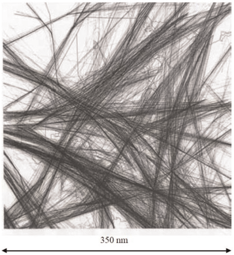
Radar tracks.
Thus, if free route airspace is considered, then it seems essential that a vigorous off-line tool should be to identify all potential collision scenarios in a three-dimensional (3D) environment with the input of predicated position coordinates while ensuring the flight safety within a foreseen time window of 10/20 min. All of the identified potential collision scenarios could be formalized in a database to match the airspace users’ reference trajectories that fly in hot-spot areas with those scenarios that can induce a collision, thereby warning pilots of highly dangerous scenarios in which a collision may occur.
By considering that TCAS is in view of the CA scenario with a local scope in a short period, the local airspace scenario will be called the basic volume, which is the greatest control volume that can be regarded as a Euclidean 3D space (not curved space). 16 General aircraft equipped with TCAS have a requirement to provide reliable surveillance out to a range of 14 nmi, 1 which could be assumed as the side-length of the basic volume. Therefore, the problem can be broken down into several sets of independent hot-spots 16 based on the basic volume; specifically, these independent sub-scenarios can be processed separately to greatly improve efficiency. Figure 2 presents a visual display of the airspace, which consists of many adjoining basic volumes. The global airspace can be considered a mesh of independent volume units distributed along the space region that is parallel considered in the identification of TCAS failures.
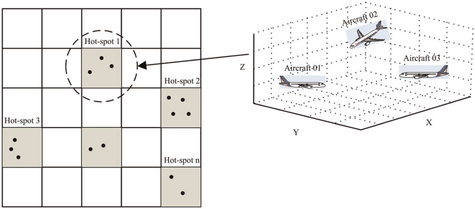
Graphical representation of basic volume.
This study aims to discuss the evolutionary states that concern multiple aircraft in a basic volume, thereby searching out the scenario that leads to TCAS failure. Although there would be a large number of aircraft in the airspace, a highly efficient method for avoiding redundancies in the solution space is clustering, which reduces the general problem to several sets of independent scenarios (known as clusters) in a partial scope. 16 A scenario of three aircraft in a basic volume (local region) is used to describe the problem in our research and its conceptual scenario is illustrated in Figure 3. Because of the wind influence, pilot behaviors, or aircraft performance errors, the speed vectors of the three aircraft may be variable in a certain range during the execution phase; thus, this leads to different possible future situations (state space) in which several potential collision scenarios could be induced.
Three-aircraft scenario.
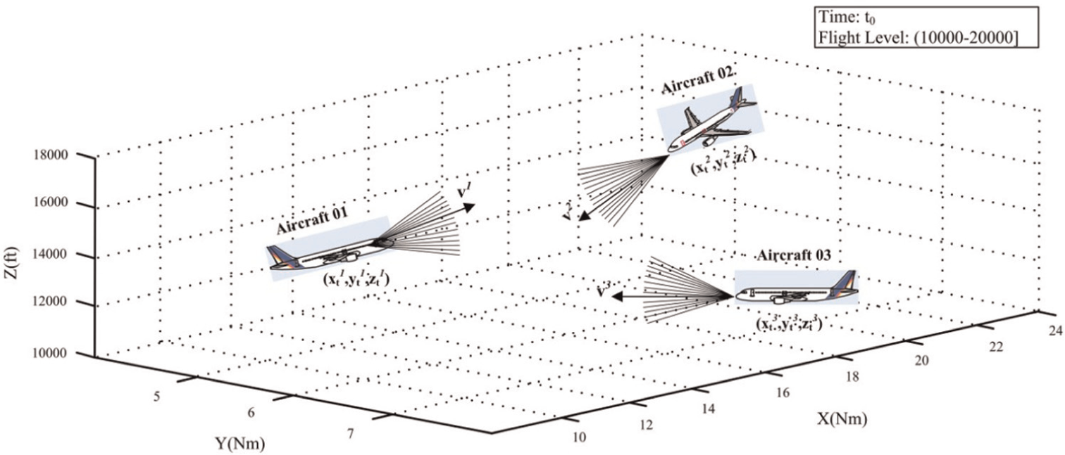
This study has been developed with an assumption of four-dimensional (4D) trajectories (sequence of 3D position of an aircraft together with its time stamp), TCAS II-equipped aircraft, and en route traffic. When accounting for the vertical, lateral, and longitudinal bearings, the position and speed both have 3D components. For the ith aircraft, its dynamic characteristics could be described in a Cartesian coordinate system, 20 as shown in Figure 4. The region formed by the x- and y-axes indicates the horizontal plane, and the z-axis represents the altitude. Euclidean spaces make the construction of the basic volume simpler; thus, a planar projection of the Earth has been considered by using a coordinate system (x,y,z) with a minimum distortion.
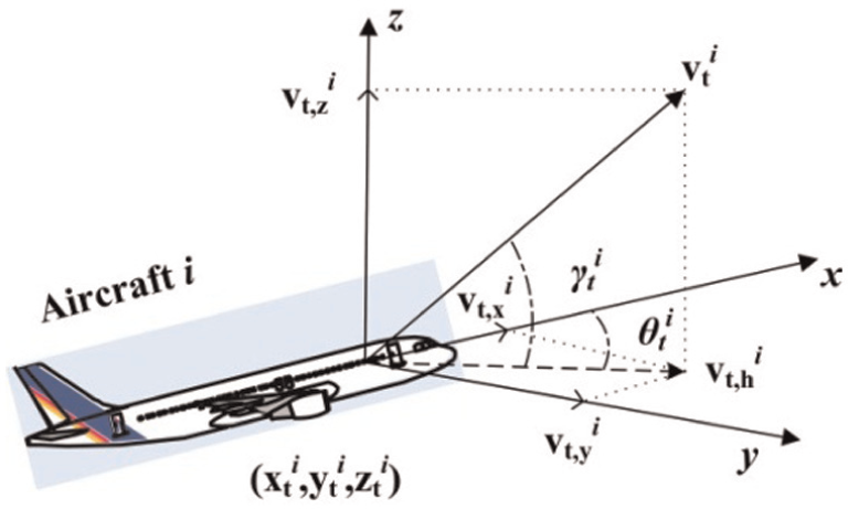
Velocity vector in a Cartesian coordinate system.
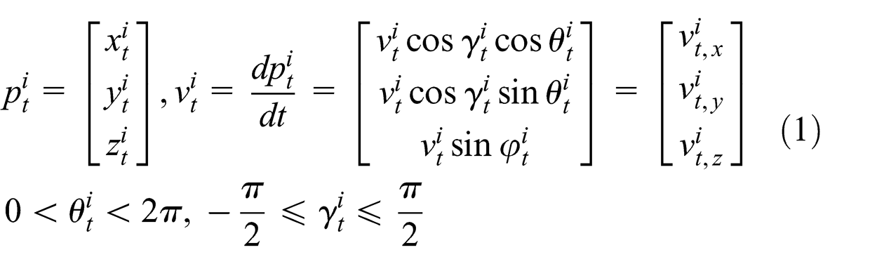
The formula defines
For safety issues, it is desirable to perceive all of the TCAS failure situations between the involved aircraft of this scenario, and the merely known input data are the initial 3D coordinates of the aircraft, while their initial speed vectors are variable. The state space for the TCAS failures analysis consists of different combinations of the feasible speed vectors comprising all the situations in which the aircraft could evolve when considering the interdependencies between the trajectories and the TCAS directives.
3. State space analysis and the Colored Petri Net
In this study, the TCAS logic has been modeled to analyze the cause-and-effect relationships between the actors that could potentially interact in a scenario. The established causal model formalizes a number of causal relationships between successive events (separation minima lost, RAs, TAs, and maneuvers) that produce a phenomenon (state of the system) by which an event can be interpreted as a consequence of the previous one, 21 which corresponds to the central concept of the Petri Net (PN), and the enhanced version, the CPN. 22
Although there are several formalisms to explore the system dynamics, such as an automaton, Markov chain, timed automata, PN, CPN, min-max algebra, etc. (summarized by Dorfman and Medanic 23 ), the PN and CPN formalisms are versatile and well-founded modeling languages that can be used in practice for systems of the size and complexity found in this industry. 21 The CPN is a graphical and discrete-event modeling language that combines the capabilities of the PN with the capabilities of a high-level programming language. The PN provides the foundation of the graphical notation and the basic primitives for modeling concurrency, communication, and synchronization toward a very broad class of systems, but it is intended to be a general modeling language, that is, it does not aim to model a specific class of systems. Both the PN and CPN have been employed to describe the synchronization of concurrent processes, but in particular, the CPN provides the strength that is required to define data types and manipulate data values. 24 The CPN has been used to verify and validate systems through property analysis and, more recently, the state space analysis tool has been used to explore the dynamic evolution of a system and to determine all of the possible future states that are reachable as initiated from a given current state vector. In Tang et al., 25 a CPN model is introduced as a key approach to analyze the state space of a specific congested traffic scenario in which a potential collision may exist, and the inputs are the predicted trajectories of all involved aircraft. This paper aims to discuss the evolutionary states that concern multiple aircraft with known initial positions in a basic volume, thereby searching out the scenario that leads to TCAS failure, which could help ATC to ensure the flight safety within a foreseen time.
The CPN is a high-level modeling formalism for complex systems that has been widely used to model and verify systems, allowing the representation of not only the system dynamics and static behavior but also the information flow. 26 The CPN is a graphical language that combines the capabilities of a PN with the advantages of a high-level programming language, for constructing models of concurrent systems and analyzing their properties. A CPN model can be defined as the following nine-tuple: 26
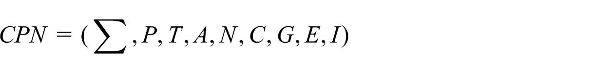
in which the different elements between the parentheses represent the color set, place set, transition set, arc set, node function, color set function, guard function, arc expression, and initialization function, respectively.
The formalism can be graphically represented by circles, called place nodes; rectangles or solid lines, called transition nodes; and directed arrows, called arcs, that connect one transition with one place node or a place node with one transition. To model the occurrences of activities, the input place nodes to a transition node must have at least the same number of entities (called tokens) as the correspondent arc weight, and the colors of the potential tokens must satisfy the expressions associated with the colors in the arc expressions. The Boolean condition attached to the transition (guard) is the final restriction that must be fulfilled for the transition to occur. When all of the latter conditions are satisfied, then the transition can be “fired”, which means that the entities that satisfy the mentioned conditions are destroyed from the original input place nodes and that new entities (i.e., tokens) are created in the output place nodes of the transition. The new tokens are created with the characteristics and quantities stated in the colors and output arc weights, respectively.
The state space of the TCAS logic applied to a partially certain scenario (only the initial positions are known) allows for the following.
The generation of the possible initial velocity vectors of each aircraft involved in this scenario.
All of the maneuvers that can be issued by TCAS when considering the air traffic scenario (markings) that can be reached starting from certain initial system conditions (traffic scenario).
The transition sequence to be fired to drive the system from a certain initial state to a desired end-state. In this context, end-states are those states in which TCAS logic would fail due to an unreasonable sequence of RAs.
4. Development of the Traffic Alert and Collision Avoidance System model using the Colored Petri Net formalism
In general, during normal flight, the aircraft receives instructions from the ATC and flies according to these instructions; at the same time, TCAS is constantly surveying the surrounding airspace, by broadcasting interrogations and receiving responses from nearby aircraft. A reduction in the separation minima can occur due to several circumstances, such as when the ATC system issues a threat resolution in time that is not translated into a desired change in aircraft speed, direction or climb/descent rate, or when the aircraft (manually or using the autopilot) executes a maneuver that the controller had not anticipated. 27
For two aircraft that are both equipped with TCAS, when an encounter is declared, a two-step process is followed to select the cooperative RA for the threat geometry. The first step is to decide the appropriate sense (upward or downward). Based on the range and altitude tracks of the involved aircraft, the TCAS logic models their flight paths from their current positions to the closest point of approach (CPA), and then it selects an opposite sense RA for each aircraft, as shown in Figure 5. The aircraft that would be in the higher altitude at the CPA climbs while the other descends, which would provide a minor change in the vertical speed. The second step is to determine the RA strength that is the least disruptive to the existing flight path while still providing at least Altitude Limit (ALIM) feet of vertical separation between the two involved aircraft at the CPA. This means that the amendment of the vertical velocity
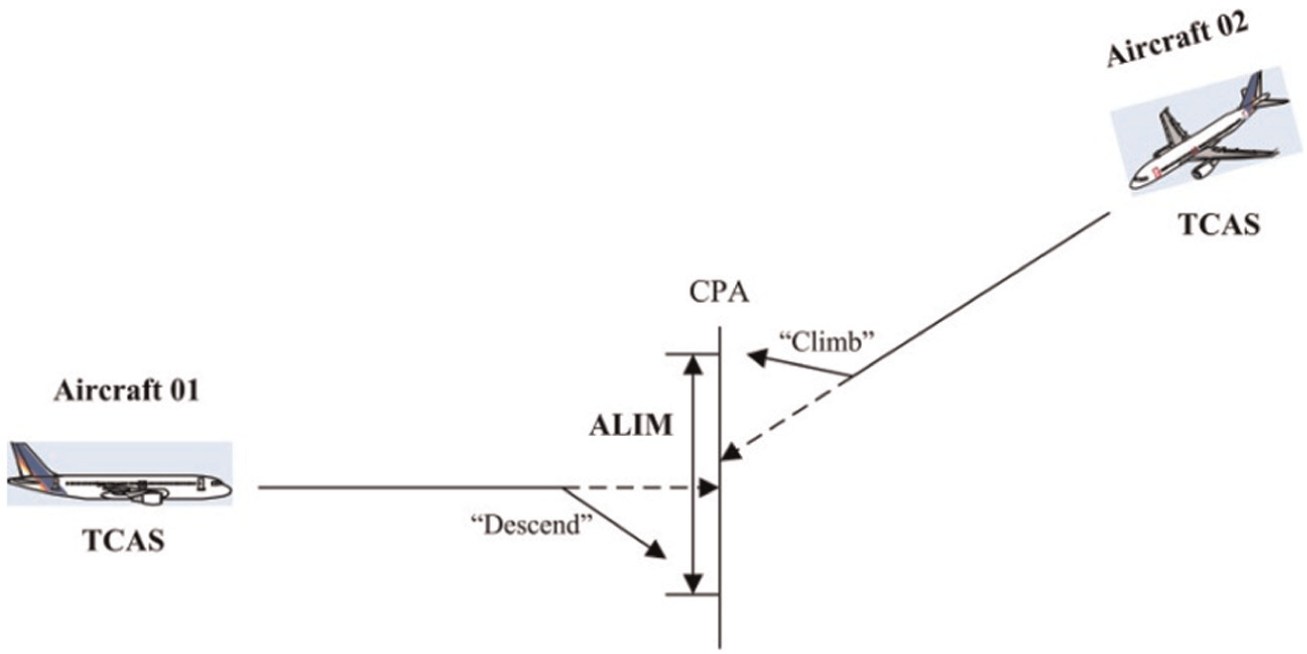
Opposite sense selection for each aircraft.
4.1 Causal model based on TCAS II logic
By considering the different vector velocities of each aircraft, and the RAs generated by TCAS considering the particular interdependencies between one-on-one encounters, a discrete model to generate the state space has been implemented to detect those collision states induced by TCAS to enable an analysis of the sequence of events that lead to each collision state. Because some events correspond to RAs generated by TCAS, the analysis would enhance those changes in TCAS logic by considering the surrounding traffic to avoid present TCAS shortages.
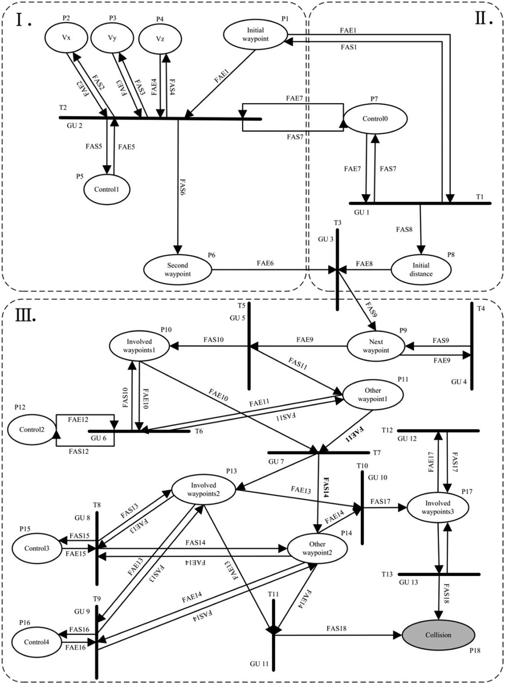
The proposed model considers aircraft trajectories as a sequence of 3D waypoints that the corresponding aircraft will follow, with the sequence containing the positions and speeds. The developed causal model is based on these aircraft tracking waypoints and has been specified in the CPN formalism, using 11 colors, 18 places, and 13 transitions. Figure 6 illustrates the model that is implemented in CPN, which mainly consists of three blocks of transitions that represent three different control events.
Generate the amendment speed for the aircraft in a scenario. In this block, the event that generates the motion state of each aircraft, which corresponds to one transition (T2), randomly selects the constant options in spatial coordinates (x,y,z).
Screen out usable situations. The second block contains two transitions (T1,T3) that specify the events of abandoning situations that would never initiate a threat: T1 calculates the distance between each pair of aircraft in the current positions; T3 computes the distance between the second waypoints and compares them to the results of T1, eliminating the circumstances when the aircraft are separate from each other because no conflict will occur.
Resolve the detected conflicts and seek out the TCAS logic failure states. The third block contains 10 transitions (T4, T5, T6, T7, T8, T9, T10, T11, T12, T13): firing T4 means that the aircraft flies to the next waypoints; if the first conflict is detected, then T5 fires; T6 runs to resolve the primary conflict based on the RAs (the aircraft in the higher altitude climbs while the other one descends), until a domino conflict induced by the destabilizing network effect is detected (T7); T8 and T9 have a function that is similar to T6, which is to resolve the current two conflicts; however, if the negative domino conflict cannot be resolved, then T11 is executed and the place “Collision” keeps the corresponding data; T10 is used to consider the subsequent domino conflicts, and T12 attempts to resolve them; however, in the resolving process a collision could occur and the spatial information of the involved aircraft are then transferred to the place “Collision” by T13.
Causal model for Traffic Alert and Collision Avoidance System logic.
4.2 Net specification and description
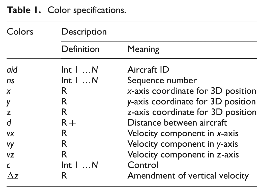
The colors used to describe all of the information that are required in the relevant places are summarized in Table 1.
Color specifications.
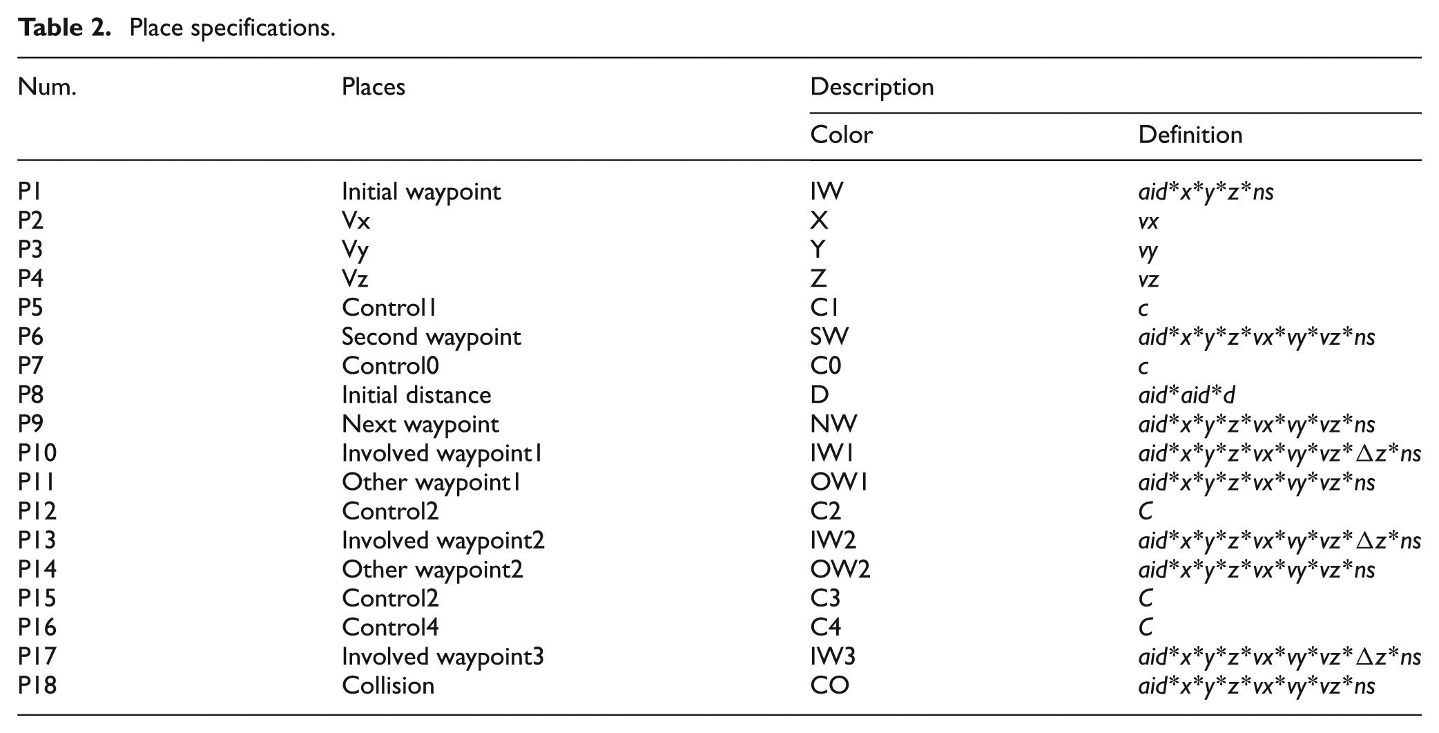
The specifications of the main places are shown in Table 2, and the operations are detailed as follows.
Place “Initial waypoint” contains five color attributes to define the original position information of an aircraft: aid signs the ID of corresponding aircraft; (x,y,z) show the 3D coordinates; and ns marks the sequence number of the current waypoint, which is equal to zero here. For example, if 1′(1,6.782,6.237,15570,0) + 1′(2,8.956,6.548,15340,0) + 1′(3,22.183,6.641,14800,0) are in this Place, it means that three aircraft with corresponding positions are involved in the scenario at time 0.
Place “Initial distance” possesses the calculated distance d between each pair of aircraft aid1 and aid2.
Places “Vx”, “Vy” and “Vz” separately hold several tokens with only one color ns as the constant options of initial velocity in each bearing.
Place “Second waypoint”, as its name implies, stores the position (x,y,z) and speed (vx,vy,vz) information of the second waypoint (ns = 1) of aircraft aid.
Place “Next waypoint” keeps the data of serious waypoints in the normal flight without conflict, having the same color attributes as Place “Second waypoint”.
Places “Control0”, “Control1”, “Control2”, “Control3”, and “Control4” own one color c as the subsidiary condition cooperating with corresponding Transition to realize its control function.
Place “Involved waypoint1” memorizes the waypoint information of the involved aircraft that have the primary conflict, while Place “Other waypoint1” holds the remaining aircraft that are irrelevant to this conflict; Place “Involved waypoint2” stores the information of the involved aircraft that have a domino conflict initiated by the first conflict, while Place “Other waypoint2” preserves the others; and Place “Involved waypoint3” keeps the data of subsequent domino conflicts, while all of the collision situations are collected in Place “Collision”.
Place specifications.
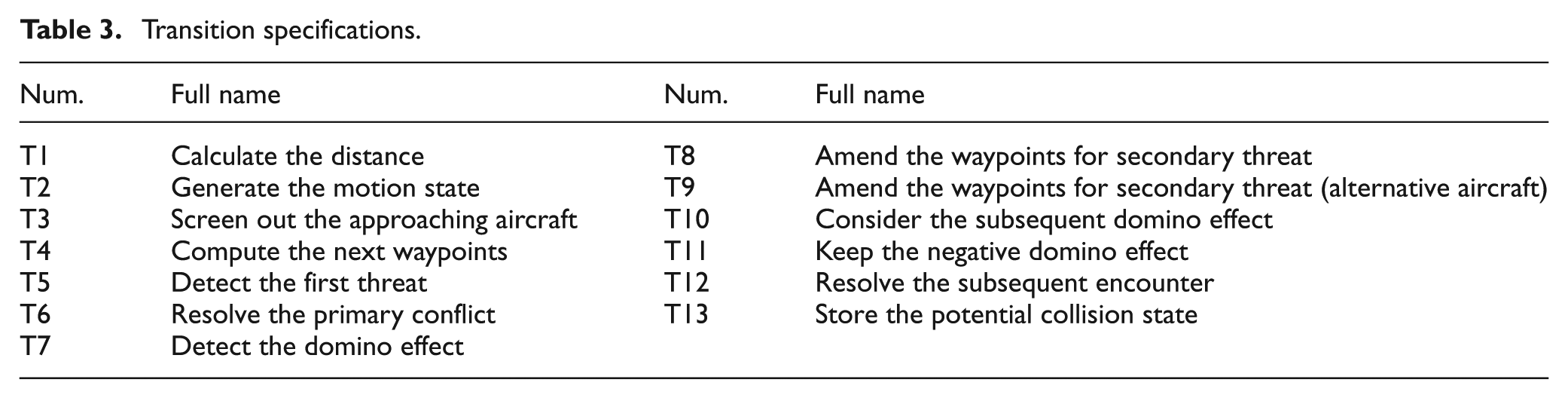
The full names of the Transitions are shown in Table 3.
Transition specifications.
4.3 Event specification example
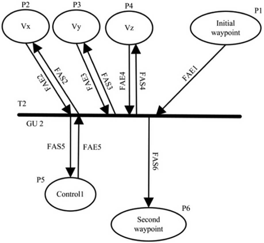
To show how the proposed CPN model works, one of the 13 transitions is explained. Figure 7 illustrates the transition T5 “Detect the primary threat”, in which information that is stored in three places is evaluated.
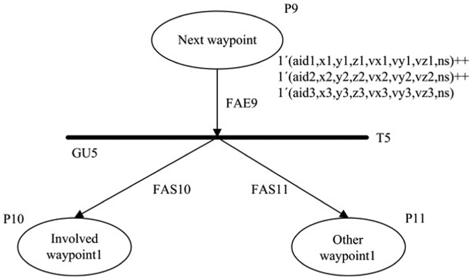
Example of the causal model.
Place “Next waypoint” provides the position and speed information of the aircraft in a scenario, and here it contains three tokens 1′(aid1,x1,y1,z1,vx1,vy1,vz1,ns), 1′(aid2,x2,y2,z2,vx2,vy2,vz2,ns), and 1′ (aid3,x3,y3,z3, vx3,vy3,vz3,ns), which separately indicate the states of the three aircraft aid1, aid2, and aid3. Note that the waypoints have the same ns, which implies that they are at the same time. If they meet the guard function GU5, T5 fires, and the two involved waypoints that have a threat will be transferred to P10 by the arc expression FAS10, while another waypoint will be sent to P11 by FAS11. In this context the arc expression is signed in the format of FAXY, where X represents the arc type (E for input and S for output), and Y represents the place identifier.
To determine whether an encounter exists, both the range and the vertical criteria must be satisfied. To check whether they are both satisfied, the Range test and Altitude test are constantly performed during the flight. The calculation methods are completely based on the TCAS II logic. 20
Range test
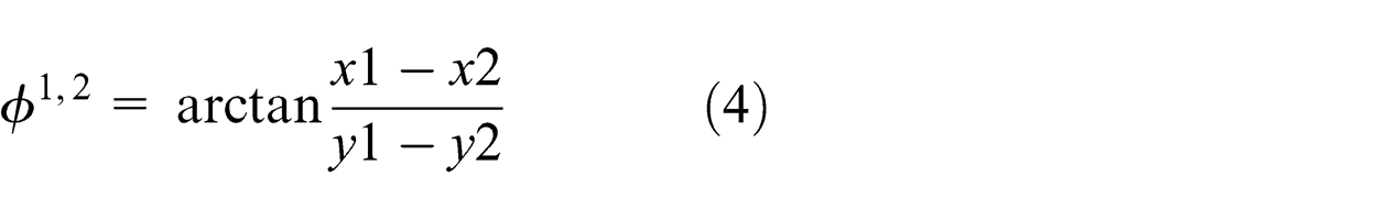
For the nsth waypoints (which can be regarded as being at the moment ns), both the distance and the relative velocity between each pair of aircraft in the horizontal plane are calculated. Knowledge about both values is required to calculate the time to the CPA.
Consider the aircraft aid1 and aid2, for example. The distance and the relative velocity in the horizontal plane between aid1 and aid2 at time ns are
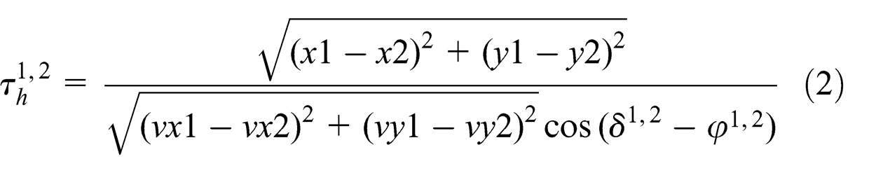
with
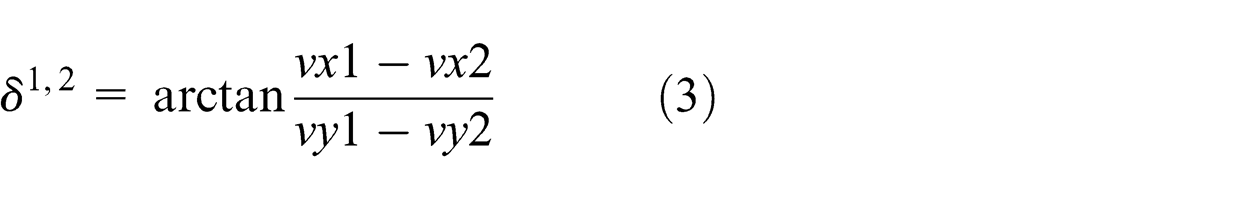
with
Obviously, the denominator of Equation (1) cannot be zero:
Altitude test
For the nsth waypoints, both the separation and the vertical closing velocity between each pair of aircraft in the horizontal plane are calculated. Knowledge about both values is required to calculate the time to CPA.
The distance and the relative velocity in the vertical plane between aid1 and aid2 at time ns are
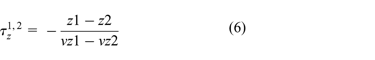
Equation (5) is defined under the condition that
Threat detection
Compare the calculated values with the known constants (Distance Modification (DMOD) and ALIM are given in US Department of Transportation1) in this FL, and if the following conditions are satisfied:
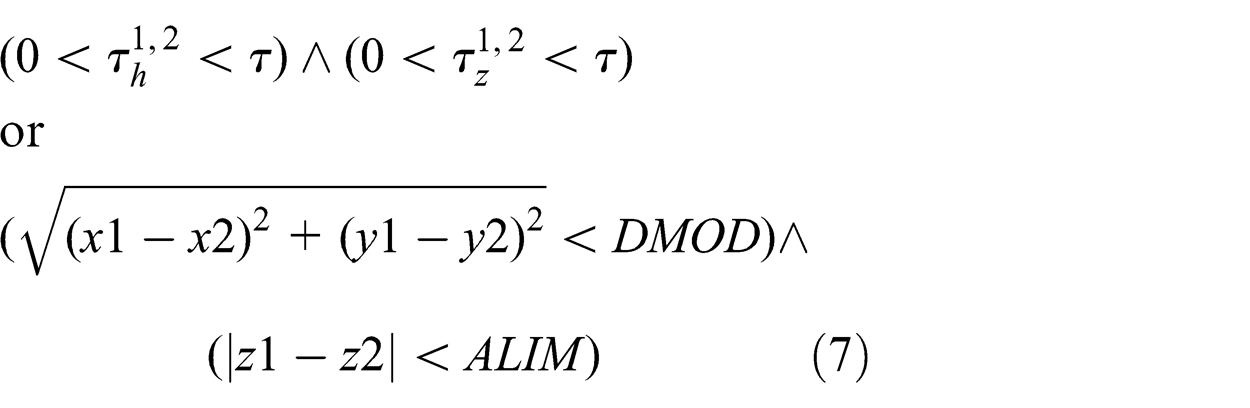
then a threat is detected.
The guard function of GU5 is shown in Figure 8, in which ①, ②, and ③ separately indicate the threat between aid1 and aid2, the threat between aid1 and aid3, and the threat between aid2 and aid3, assuming that the DMOD is equal to 0.8 Nm while the ALIM is 400 ft in the FL of 6. 20 If any one-on-one threat between the three aircraft is detected, that is, ① or ② or ③ is satisfied, then T5 fires.
GU5 representation.
The arc expression of FAS10 is
if ①, then 1′(aid1,x1,y1,z1,vx1,vy1,vz1,ns)++ 1′(aid2,x2,y2,z2, vx2,vy2,vz2,ns);
else if ②, then 1′(aid1,x1,y1,z1,vx1,vy1,vz1,ns)++1′(aid3,x3,y3,z3,vx3, vy3,vz3,ns);
else 1′(aid2,x2,y2,z2,vx2,vy2,vz2,ns)++1′(aid3,x3, y3,z3, vx3,vy3,vz3,ns).
The arc expression of FAS11 is
if ①, then 1′(aid3,x3,y3,z3,vx3,vy3,vz3,ns);
else if ②, then 1′(aid2,x2,y2,z2,vx2,vy2,vz2,ns);
else 1′(aid1,x1,y1,z1,vx1,vy1,vz1,ns).
4.4 Generation of velocity vectors
An innovative method is first presented to simulate the initial feasible speed vector generation, which provides several options for random selection in each 3D axis. Figure 9 presents its specification in the CPN formalism.
Initial velocity generation module.
Considering the initial speed in the x-axis as an example, the changes in the initial speed could be various, from several negative to several positive options, such as
5. Simulations and results
In this section, we perform simulation experiments to evaluate the TCAS logic performance using the proposed CPN model. Firstly, three case scenarios with different initial positions for the involved aircraft are operated to explore the situations of TCAS failures to resolve the threats, and the simulation results are analyzed to draw conclusions. Then, to test the effectiveness of the results that were generated by the causal model, an example of a collision is illustrated using the Interactive Collision Avoidance Simulator (InCAS, developed by EuroControl), which is a software tool that is designed for the subsequent analysis of incidents in which avoidance is provided by TCAS. Finally, the average computation times of multi-aircraft are presented and discussed. The coverability trees (state spaces) were obtained by using Radius (Radius is a prototype tool for the exploration of reachability from CPNs, developed by UAB). 28 The simulation results demonstrate that the TCAS logic performs well in encounters in which it is activated and is intelligent enough to face most situations. However, some special scenarios in which TCAS may fail still exist.
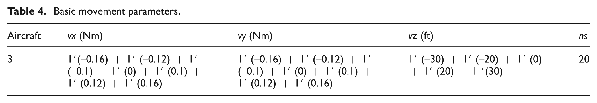
Table 4 summarizes several basic movement parameters in the causal model for the simulations of different scenarios. There are three aircraft and the amendment options for the initial speed vx, vy, and vz are depicted in each column. Note that ns is a restriction of the sequence number, and here, ns equal to 20 means that if there is no threat in the first 20 waypoints in the simulation basic volume, then there would be an end-state. Table 5 illustrates the situation parameters, assuming that the three aircraft are in the sixth FL, in other words, 10,000–20,000 ft. 1 An aircraft can be modeled as a unique point in the space surrounded by a 3D safety volume shape; thus, a threat is considered to be resolved by the TCAS when the DMOD and ALIM of both aircraft overlap, while TCAS logic fails to avoid the collision when the Hcl and Dcl volumes of both aircraft overlap, as shown in Figure 10. Normally, Dcl is the average length of the aircraft fleet operating in the basic volume (or wingspan if longer) while Hcl is the average height of the aircraft fleet operating in the basic volume. The values of Hcl and Dcl can be obtained from EuroControl. 29
Basic movement parameters.
Situation parameters.
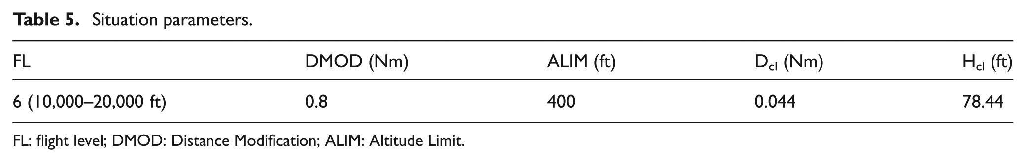
FL: flight level; DMOD: Distance Modification; ALIM: Altitude Limit.
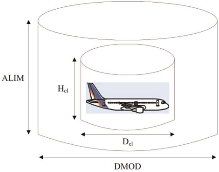
Aircraft cylinder shape.
5.1 Count of TCAS logic failures
Table 6 shows the states for which the TCAS logic fails to resolve the threat generated by the causal model, and it contains the analysis results of three scenarios. The simulated encounters reflect all possible future situations (13,824,000 possible states in this simulation) from the initial situation, including several complex situations that occur in the basic volume when TCAS must issue RAs in response to more than one threat. Simulations help us to test TCAS performance in encountering geometries and discovering failure states that might be quite rare in reality, but free flight has zero tolerance for any dangerous situations.
Simulation results of three situations.
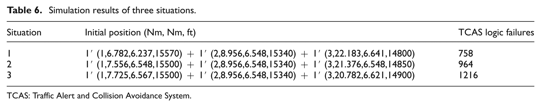
TCAS: Traffic Alert and Collision Avoidance System.
By means of state space exploration based on the proposed model, scenario 2, which involves three aircraft whose initial positions are (7.556,6.548,15500), (8.956,6.548,15340), and (21.376,6.548,14850), addresses 964 states in which the TCAS logic fails to avoid a collision. Note that two other scenarios, scenario 1 and scenario 3, which are presented in Table 6, are used for comparison. The initial position of aid2 remains unchanged, and the coordinates of aid1 and aid3 are amended to alter the distances between them; the results evidently indicate that there would be more states of TCAS logic failures when they are closer. This finding confirms the common belief that increased traffic density in a basic volume will likely lead to a higher number of collisions between aircraft.
5.2 Example failure
InCAS is an interactive system for evaluation, study, demonstration, and training on TCAS, and it is designed to simulate incidents that provide a relatively exact reconstruction of reality. Therefore, InCAS is used in our research to validate a TCAS logic failure state of the scenario that contains three aircraft (Boeing 737-800). Table 7 depicts the detailed aircraft properties.
Aircraft properties.
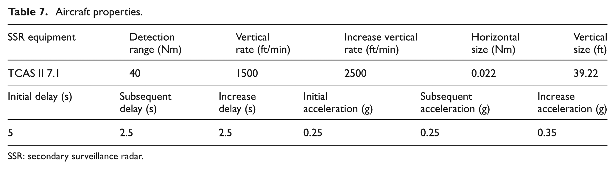
SSR: secondary surveillance radar.
The scenario comprises three aircraft: aid1 is cruising at FL155; aid2 is descending from FL165; and aid3 is climbing from FL145. In normal flight, TCAS on the aircraft incessantly surveys the surrounding airspace, by sending inquiries and receiving responds from neighboring aircraft. Thus, when aid3 flies into the range (time, τ) of aid2, a TA is issued by TCAS to warn the crew of aid2 that a collision is predicted to occur within
Table 8 illustrates the waypoints of a partial trajectory of each aircraft before the collision occurs (For simplicity, the data are recorded every 2 s). At 20:14:23, aid1 and aid2 burst into each other’s collision safety volume, their horizontal distance is
Waypoints of partial trajectory.
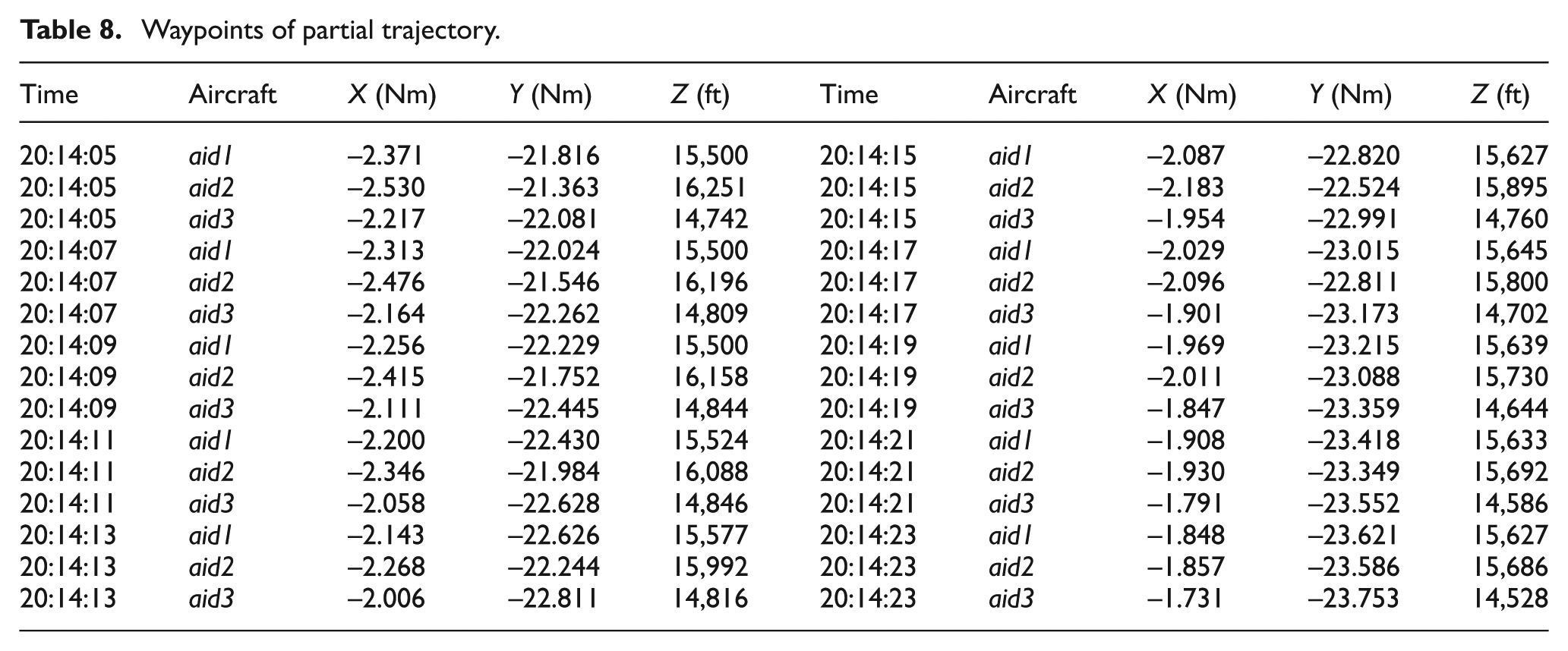
Figure 11(a) shows the horizontal view (x–y coordinates, graduated in Nm), while Figure 11(b) shows a vertical encounter view of the scenario (time–altitude coordinates, graduated in FL for altitude). The radar plots stick to the original trajectories, and the modified trajectories are displayed in dotted lines.
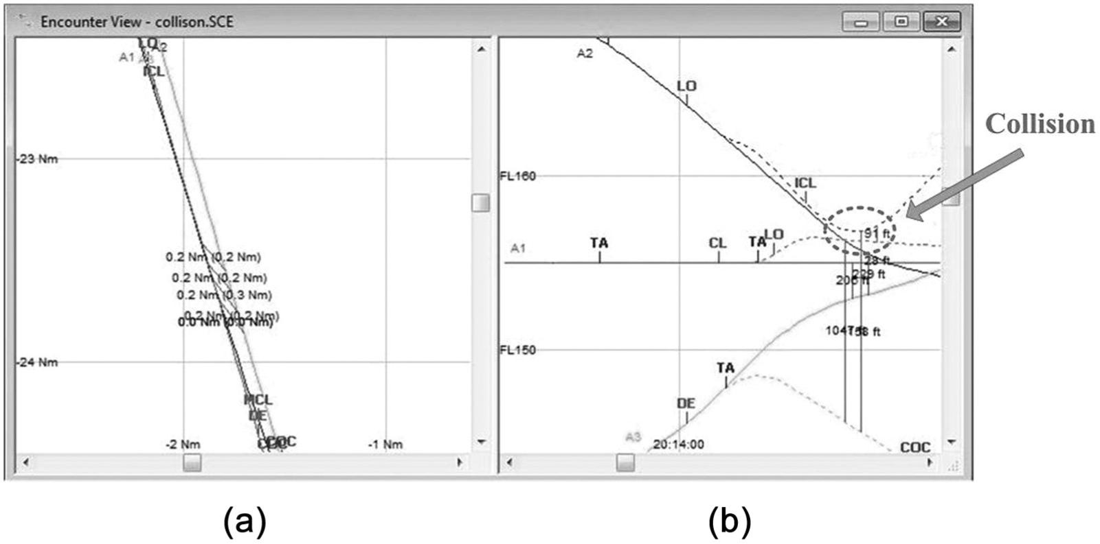
Encounter view.
The three-aircraft scenario that is simulated with the InCAS software reflects a relatively complex situation that is designed while referring to the TCAS logic failure state of a causal model. The result of the scenario to test the TCAS performance in the encountered geometries shows that it is challenging for the present TCAS to handle all of the situations that could occur in future airspace that would have higher aircraft density as noted in this paper.
5.3 Computation time discussion
Based on the generation of vector velocities for all aircraft involved in a scenario (i.e., surrounding traffic), the causal model could be extended to determine all the collision scenarios for a particular amount of aircraft whose initial positions are given.
Although there would be a large number of aircraft in the entire airspace, the aircraft number should be only a few if the view is limited in the local region (basic volume). In addition, according to Billingsley et al., 10 multi-aircraft scenarios with only three aircraft realistically comprise over 95% via analyzing the distribution over the number of aircraft involved in a multi-threat scenario; there is only one scenario involving seven aircraft among the 3803 multi-threat scenarios identified based on the radar data from FAA and Department of Defense sites throughout the United States. Thus, the causal model is extended to generate the state space of different numbers of aircraft involved in a local situation and the average computation times are presented in Table 9.
Average computation time of multi-aircraft. Test case of random initial positions (averaged over 20 runs).
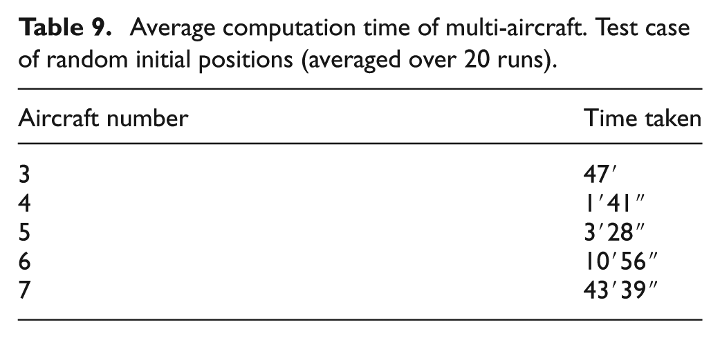
The average computation time of multi-aircraft increases exponentially according to the number of aircraft involved in the surrounding traffic. Because there is a physical saturation of the amount of aircraft in a basic volume there is no need to implement a collision identification model for a large number of aircraft. Based on the results summarized in Table 9, the proposed model could be used at the tactical and operational levels to provide an alert concerning those scenarios in which TCAS could fail by matching the reference trajectories with those scenarios (typically three, four, or five aircraft in the surrounding traffic) generated by the proposed causal model.
6. Conclusions
This paper presents the development and application of TCAS operations when using the CPN formalism, and it creatively generates all future possible states (state space) of the involved aircraft in a scenario over a period of time. The motivation for the development of this causal model is to identify TCAS shortages, and to support the follow-up research for the safety analysis of current and advanced ATM concepts including TCAS. The main contributions of this paper are as follows.
An amendment speed generator (ASG) that generates the changing speed (vx,vy,vz) of each aircraft in an initial situation by randomly selecting the constant options in spatial coordinates (x,y,z) is creatively proposed, and it has an instructive function for the trajectory generation and representation in the future discrete system.
The complete CPN model is proposed in such a way that it is absolutely based on the TCAS II version 7.1, which potentially enables a centralized and unabridged view of the current state space of the TCAS and its evolution along time. This approach is a key contribution of this research because it provides a global perspective on the scenario dynamics and a better understanding of the collision occurrence. This approach can be used to assess the impact and effectiveness of the local decisions.
There is no denying that the state space that is generated by the causal model could contain the entire possible incident sequences; however, the approach would present the well-known state exploration problem that the state space becomes so large that it cannot be fully constructed. The essential purpose of this research is to diagnose the collision possibilities rather than every reachable state; thus, some techniques that avoid the construction of all the sequences can be utilized, for example eliminating the circumstances that the aircraft are separate from each other because no conflict will occur.
Quantitative measurement experiments are conducted in InCAS to validate the feasibility and effectiveness of the causal model.
Beyond that, to accomplish the fundamental purpose of our research the next step is to utilize the proposed causal model to promote the improvement of the current TCAS logic, which is intended to address the future traffic, which is expected to be highly hectic and congested.
Footnotes
Funding
This work was supported by the Ministry of Economy and Competitiveness in the project “Fire Guided Unmanned Aircrafts and Resources Distribution (FireGUARD), CICYT Spanish program TIN2011-29494-C03-01. Support for Tang Jun from the China Scholarship Council is also acknowledged.
Author biographies