






Abstract
In this paper, a new Lyapunov-based adaptive control scheme for the position tracking of an electro-hydraulic Stewart–Gough platform type six-degree-of-freedom (DOF) driving simulator is proposed. The kinematics and the dynamics of both the moving platform and the hydraulic actuator are first derived, and the linearized dynamic equation of the moving platform is developed for the controller design. Two control loops are employed, in which the platform controller is in the outer loop and the actuator controllers are in the inner loop. In the platform controller, the compound proportional-differential (PD) feedback and adaptive compensation controller is designed. The PD part is used to create the principal control signal, and the adaptive part is used to compensate for the parameter uncertainty and external disturbance. To suppose that the upper bound of the perturbation is known, a gradient descent method-based adaptive law is developed for parameter estimation. For each actuator controller a servo force control scheme is designed to ensure the actuator to accurately track the desired force output by the platform controller. All the controllers are designed together based on the Lyapunov method to guarantee the stability of the whole system. Numerical simulation on a six-DOF simulator shows that the proposed control scheme has better tracking performance than its non-adaptive counterpart.
Keywords
1. Introduction
A driving simulator is an effective equipment for training car drivers and testing on-board instruments, and it usually employs a Stewart–Gough (S-G) platform type six-degree-of-freedom (DOF) parallel mechanism. Since this mechanism was put forward as a tire test machine by Gough in 1956 and proposed as a flight simulator by Stewart in 1965,1–3 it has attracted much research interest. In recent years, the S-G platform has been widely used in flight or vehicle motion simulation, manipulating additionally complicated surface machining and multi-dimensional vibration isolation. 4
For the driving simulation, to simulate the motion of a vehicle and provide an immersing driving sense, a S-G platform type simulator is required with a high dynamic performance, especially the position tracking accuracy. There are difficulties in improving the position tracking, as the simulator has the following characteristics. The dynamics of the S-G platform mechanism is nonlinear and highly coupled because each leg exerts some disturbance on others by the moving platform. In addition, the system also has parameter uncertainties, external disturbance and high-order unmodeled dynamics. A large number of highly nonlinear terms in the dynamic equation will cause a heavy computation burden in the model-based control strategies for the platform. 5 Additionally, an electro-hydraulic S-G platform also introduces the nonlinear dynamics of servo-valves and hydraulic cylinders into the system. Therefore, the high-accuracy tracking control of this platform is a challenging issue. The dynamics of the S-G platform has been studied by a number of methods, such as the Newton–Euler method, virtual work principle and Lagrange equation.6–8 Lee et al. 9 proposed the approximate dynamics in the position control of the S-G platform and simplified the nonlinear coefficient matrices into constant ones on the small motion range condition of the platform. Chen et al. 10 employed the experimental method to estimate the inertial parameters and friction coefficients for an electro-hydraulic motion simulator by means of the least squares method. Much research work has been done to improve the tracking performance, and some control strategies have been used on this platform. Kang et al. 11 proposed the robust tracking controllers in both Cartesian coordinates and actuator coordinates; Huang et al. 12 designed a sliding-mode controller and presented the stability analysis based on Lyapunov stability theorem to guarantee that the motion tracking error converges to zero asymptotically. Other sliding-mode control designs included the direct sliding-mode controller, integral sliding-mode controller and adaptive sliding controller.13–15 However, the above studies did not consider the hydraulic actuator dynamics. Other control methods, such as generalized predictive control, 16 H-infinity control 17 and adaptive control, are also used for the S-G platform. 18 The adaptive control in Huang and Fu 18 supposed the overall system parameters are subject to uncertainties and did not consider the external disturbance. Adaptive control uses the on-line parameter estimation method for the real-time parameters of the control plant to ensure that the control law has satisfactory performance when the plant parameters are completely unknown and/or could change with time. 19 Adaptive control has been successfully applied in many fields, such as aircraft autopilots and complicated industrial process control.20,21
In this paper, we propose a new adaptive control strategy for the position tracking of the S-G platform with perturbation of both parameter uncertainties and external disturbance. We suppose the upper bound of the perturbation is known. We consider both the platform dynamics and the actuator dynamics, and employ two loops with the platform controller in the outer loop and the actuator controllers in the inner loop in the overall control scheme. In the platform controller, the compound proportional-differential (PD) feedback and the adaptive compensation controller is designed. The PD part is used to create the main control signal, and the adaptive part is used to compensate for the parameter uncertainty and external disturbance. For the actuator controllers in the inner loop, we designed a servo force controller to ensure the actuator accurately tracks the desired force, which is output by the platform controller. The main differences between this work and Wu and Gu 15 are that the latter used an adaptive controller to identify the constant uncertain parameter, plus a sliding controller to eliminate the influence of uncertain parameters and the external disturbance, and it did not consider the dynamics of hydraulic actuator. Our method uses a PD controller plus an adaptive controller to compensate for the parameter uncertainty and external disturbance, and considers the hydraulic actuator dynamics and control. All the platform controller and the actuator controllers are designed together based on the Lyapunov method to guarantee the stability of the whole system. Finally, simulation is completed to validate the proposed method.
2. Driving simulator dynamics
The S-G type driving simulator consists of a fixed base, a moving platform and six variable-length legs to connect the fixed base and the moving platform (see Figure 1). The connection of the fixed base and each leg is through a universal joint, and that of the moving platform and each leg is through a universal joint or spherical joint. For an electro-hydraulic S-G platform, each leg employs a hydraulic servo-actuator, which can perform accurate motions controlled by the servo-valve.
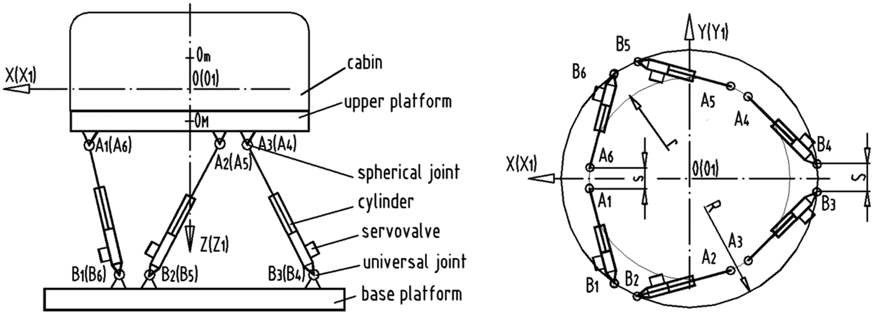
Schematic diagram of the six-degree-of-freedom Stewart–Gough platform type simulator.
2.1. Kinematics and dynamics of themoving platform
To describe the motion of the moving platform, two coordinate frames are established with one designated O1-X1Y1Z1 (hereinafter referred to as {p}) moving with the platform and another designated O-XYZ (hereinafter referred to as {b}) fixed on the ground, as shown in Figure 1. These two coordinate frames coincide when the moving platform is in its initial neutral position. A generalized coordinate vector
where, for notational simplicity, Cα, Cβ and Cγ represent cos(α), cos(β) and cos(γ), respectively, and similarly Sα, Sβ and Sγ represent sin(α), sin(β) and sin(γ), respectively.
Denote
where
So the length of the hydraulic cylinder can be written as
The axial speed of the hydraulic cylinder can be written as
where
Based on the Newton–Euler method, the dynamics equations of the platform can be given as
where
2.2. Dynamics of the hydraulic actuator
Each hydraulic actuator is shown schematically in Figure 2. It takes the combination form of a two-stage servo-valve and a servo force cylinder. The former includes a prepositioned two-jet flapper valve and another four-way spool valve as the power stage. The flow equations of each cylinder and valve can be written as
where

Schematic diagram of the servo-hydraulic actuator.
Substituting Equation (7) into (8) yields the following pressure dynamics:
Neglecting the leakage term
2.3. Dynamics of the overall system, includingthe platform and the actuators
Suppose that vector
where
in which
in which
in which
3. Adaptive controller design
The control scheme takes an outer loop and six inner loops combined mode, as shown in Figure 3. A platform controller in the outer loop takes the PD control plus adaptive compensation for the position and orientation tracking control of the platform in Cartesian space. Each inner loop is a servo force control that is used to make each actuator track the desired force solved out by the platform controller. In the platform controller, the nonlinear PD feedback part plays a main role, and the adaptive compensation part is used to compensate the external disturbance and modeling error when the tracking error is large. When the tracking error becomes small, the former will take the most part in the control signal. Based on Lyapunov stability theorem, both the platform controller and the servo force controller are designed together in one process and the global asymptotic stability is ensured under bounded external disturbance. The adaptive law of the mass parameters of the platforms is composed of the regression matrix of the S-G platform dynamic equation and designed by the gradient descent method.

Control scheme for the whole system.
First considering that the S-G platform is substantially a kind of parallel robot, it satisfies the following three general properties 22 :
The inertia matrix
There exists a parameter vector that is dependent on the S-G platform parameters and makes matrices
where
Define
where
Two new variables,
where
Let
According to Equation (23), an equation of
The combination of Equation (25) and Equation (11) yields
Let
where
Considering that
Define the control law of the platform controller as
where
Based on Equations (26) and (29), Equation (28) can be written as
According to the property in Equation (17), Equation (30) can be further written as
Based on the transposing of Equation (21), namely
Considering
Substituting Equation (33) into Equation (32) yields
Substituting the expression of
Because
When
Combining Equations (37) and (38) with Equation (36) yields
Let the values of
and
Based on inequalities (40) and (41), Equation (39) can be rewritten as
According to Equation (20) and the definition of
So
According to Equation (13), we can get
Define coefficient
Substituting Equation (46) into Equation (45) yields
Based on Equations (44) and (47), we can get
which guarantees
To summarize the above derivation, the control strategies of the whole system are as follows.
Platform controller:
where
Electro-hydraulic servo force controller:
Adaptive law:
4. Numerical simulation
Parameters of a six-DOF S-G platform type simulator are taken to verify the proposed algorithm. This platform is developed as a motion simulator and its structure is shown in Figure 1. All the parameters are listed in Table 1.
Parameters of the motion simulator.

Simulation tests are completed in Matlab/Simulink (see Figure 4). The platform controller, the adaptive law, the dynamic models of six actuators and the moving platform are all built with S-functions.
23
Each actuator controller is built in subsystem form with blocks provided by Simulink; the valve core control signal (Equation (51)) is completed with the “Matlab function” block in the Simulink library. Figure 5 gives the results when tracking the desired trajectories:

Simulink model for the whole system.

(a) Position tracking along the x coordinate. (b) Velocity tracking along the x coordinate. (c) Position tracking along the y coordinate. (d) Velocity tracking along the y coordinate. (e) Position tracking along the z coordinate. (f) Velocity tracking along the z coordinate. (g) Angular position tracking around the x-axis. (h) Angular velocity tracking around the x-axis. (i) Angular position tracking around the y-axis. (j) Angular velocity tracking around the y-axis. (k) Angular position tracking around the z-axis. (l) Angular velocity tracking around the z-axis.
The convergence in the six motions shown in Figure 5 testifies the global asymptotic stability of the proposed adaptive controller. Figure 6 demonstrates the rapid convergence of parameter estimation with the proposed adaptive law.

(a) Mass parameter estimation. (b) Estimation of inertial moment around the x-axis. (c) Estimation of inertial moment around the y-axis. (d) Estimation of inertial moment around the z-axis.
It can be seen from Figure 5 that by using only the PD control there exists great amplitude attenuation and phase lag in both the position and velocity tracking of all three translations, which results in large tracking errors. However, the adaptive controller shows much higher tracking performance, especially with very small error in the velocity tracking of all these three translations cases, and both the position and velocity errors gradually converge to zero. Without considering the pulse in the beginning, the maximum position tracking errors along the x, y and z coordinates are about 25%, 15% and 5%, respectively. However, the PD control has tracking errors of about 90% in all these three cases because of the amplitude attenuation and phase lag.
In the three rotations, both the adaptive controller and the PD controller show better control results: the maximum position tracking errors under the adaptive controller are about 5%, 8% and 6%, respectively. The PD controller still has a large tracking error with maximum values of about 38%, 20% and 16%, respectively, although it is better than the three translation cases. The adaptive controller still definitely outperforms the PD controller and its position and velocity tracking errors converge to zero with less fluctuation relative to the three translation cases. All the simulation results show that the proposed adaptive control algorithm has better robust performance when with parameter uncertainty and external disturbance.
5. Conclusion
This paper proposed a nonlinear adaptive control scheme for an electro-hydraulic S-G platform type simulator for motion simulation. The designed controller includes two parts: a nonlinear PD part and an adaptive compensation part. The adaptive compensation part is used to compensate for the modeling error and external disturbance and thus to effectively decrease the dynamic tracking error of the platform.
The dynamics of the electro-hydraulic actuator is also considered and a Lyapunov-based servo force control scheme is presented in this paper. The entire system, including electro-hydraulic actuators, is controlled with the combined inner and outer loop control scheme. All the controllers are designed together based on the Lyapunov method to ensure the global asymptotic stability.
Simulation demonstrated the feasibility and effectiveness of the proposed adaptive control scheme. It outperforms the non-adaptive PD control and shows better robust tracking performance.
Footnotes
Funding
This research is supported by Natural Science Fund of Heilongjiang Province of China (E201013) and the Project of Fundamental Research Funds for the Central Universities of China (DL09CB02).