






Abstract
The traditional inertial navigation system-based indoor pedestrian navigation method is not suitable to all the conditions, since its data fusion model is designed only for a single condition. In order to achieve better performance, a two-mode navigation method for indoor pedestrian navigation is proposed in this work, which includes the stance mode and the swing mode. When the person’s foot is in a stance phase, the stance mode is used to correct the velocity error and yaw error. When the person’s foot is in a swing phase, the swing mode works and only the yaw error is able to be corrected. For verification, a real indoor test has been done to assess the performance of the proposed two-mode method. The position root-mean-square error (RMSE) value is 1.9265 m during a 176-m traverse, and the RMSE of yaw is 0.20734 rad. These results demonstrate that our method is effective to reduce the error compared with the conventional schemes.
1. Introduction
Pedestrian navigation (PN) is a technology that tracks navigation information for a person traveling; it is required by numerous applications such as healthcare, the entertainment industry, and the military.1–4 Consequently, this topic has received great attention over the past few decades. In outdoor environments, the most widely used method is the global positioning system (GPS), which relies on satellite navigation systems. However, GPS still has many challenges in the indoor environment since the signals will be unreliable due to signal attenuation caused by indoor obstacles. In order to bridge GPS outage in indoor environments, some beacon-based solutions have been proposed. For example, Bahl and Padmanabhan 5 proposed a location and tracking system using the fingerprinting approach, Chumkamon et al. 6 employed radio-frequency identification (RFID) for indoor environments, and Ingram et al. 7 proposed an indoor positioning systems using UltraWideBand (UWB). The principle of the methods mentioned above is similar to GPS, which relies on a network placed at known locations, although they used different technologies, such as ultrasound, short-range radio (WiFi, UWB, RFID, Zigbee, etc.). 8 Although beacon-based solutions are able to achieve reasonable accuracy, they need extra infrastructure support, which is not easy for the determination of the locations of the beacon in some applications.
Recently, the beacon-free approach for PN has received great attention, since it is able to work without preinstalled infrastructure, 9 and the inertial navigation system (INS)-based PN solution is one of the most widely used solutions. For the INS-based PN, two main approaches are used: foot-mounted and waist-, torso-, or shoulder-mounted. 10 One famous example of the foot-mounted approach is NavShoe, proposed by Foxlin, 11 which employs a miniature inertial package to provide navigation in GPS-denied environments. The advantage of this mode is that the zero-velocity update (ZUPT) is able to be used to reduce the error growth. Therefore, many systems employ this approach.8,12–16 However, the shortcoming of this mode is that the inertial measurement unit (IMU) is difficult to place on the foot, and it has to transmit data to the data terminal equipment by using wiring or a wireless link, which makes this mode impractical in some applications. 10 Meanwhile, it also should be pointed out that although the foot-mounted approach is able to achieve good performance even by the low-cost IMU, it cannot provide long-term available navigation information, since the yaw is not observable. On the other hand, the waist-, torso-, or shoulder-mounted approaches are preferable in some applications compared with the foot-mounted approach. Several methods have been proposed for the localization of persons during the last decade. For instance, in Perttula et al., 10 a waist-mounted IMU is used for accuracy; Renaudin et al. 17 employed handheld inertial sensors for the step length estimation; and a torso-mounted IMU was used by Cheng et al. 18 for seamless outdoor/indoor navigation. Our approach is easier to achieve compared with the foot-mounted approach, and the yaw estimation is better than the foot-mounted approach since there is less vibration when the person walks; however, the velocity estimation is worse than the foot-mounted approach since the ZUPT cannot be used to reduce the velocity drift in this approach.
For the data fusion mode of the PN, many proposed researches employ a single mode. For instance, in Jiménez et al., 16 the data fusion mode is used only for the stance phase of the person’s foot; meanwhile, the data fusion mode proposed by Ali and El-Sheimy 19 also uses to one condition; only one tightly couple mode is used for indoor PN. 8 It should be pointed out that the single mode is just designed for one condition, which is not suitable for all the conditions when a person walks.
From the approaches mentioned above, it can be seen that all the INS-based PN approaches have their strengths and weaknesses. In order to achieve better performance, the combination of foot-mounted IMU and the shoulder-mounted IMU is proposed in this work. In this mode, foot-mounted IMU is used for the estimation of velocity and position, and the shoulder-mounted IMU is used for the yaw error estimation of the foot-mounted IMU. Moreover, a two-mode navigation method is proposed in this work, which divides the data fusion mode into the Stance mode and the Swing mode. The remainder of the paper is organized as follows: Section 2 gives the principle of the two-mode navigation method. The system mode is shown in Section 3. Tests and discussion are illustrated in Section 4. Finally, the conclusions are given.
2. Principle of the two-mode navigation method
The principle of the two-mode navigation method is shown in Figure 1. The coordinate frames used in this work include the body frame (b-frame) and the navigation frame (n-frame). Because the indoor navigation area is very small, the Earth’s rotation is not considered in this work. In this work, two low-cost IMUs are used; one is fixed on the foot and the other one is fixed on the shoulder. Each IMU is composed of three gyroscopes, three accelerometers, and three magnetometers, which are used to measure the angular rates (
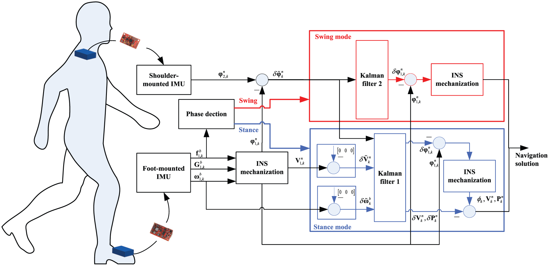
Two-mode navigation algorithm. INS: inertial navigation system; IMU: inertial measurement unit.
The mode when the person’s foot is in a stance phase is called the stance mode. In this mode, the velocities in the n-frame and angular rates in the b-frame calculated by the foot-mounted IMU are the velocity errors and the biases of gyroscopes, since the person’s foot is stationary, which are also the available measurements. Moreover, because the foot-mounted IMU is poor in yaw calculation due to its strong vibration during normal walking, the difference between the yaw measured from the foot-mounted IMU and that value measured from shoulder-mounted IMU is used as the measurement for the yaw errors of the foot-mounted IMU. Then, the output of the Kalman filter (KF) is used to correct the INS error and the optimal estimation of the velocity. Attitude is output, which is shown in Figure 1. The swing mode is the mode when the person’s foot is in a swing phase. In this mode, the yaws measured from the IMUs are the only available measurement; thus, only the yaw errors of the foot-mounted IMU are able to be corrected. In this mode, the KF is used to correct the yaw error and, then, the optimal estimation of the attitude transfer matrix is used to recalculate the navigation information, which is shown in Figure 1. Meanwhile, two conditions are used to estimate whether the person’s foot is static or not in this work, which will be described in detail in Section 4.
3. System model
In this section, the state equation and the measurement equation of the two modes will be illustrated. Because the motion states of the person’s foot and the available measurements are different, both the state equation and the measurement equation used in the two modes are different. They will be described as follows.
3.1. Model for the stance phase of the person’s foot (stance mode)
In the mode for the stance phase of the person’s foot, a 15-element vector,

where
When the person’s foot is stationary, its true velocity is zero. Thus, the velocities calculated by the foot-mounted IMU are the velocity errors. Meanwhile, the true angular rates are also zero, and the values measured from the foot-mounted IMU are the error in the angular rate. Moreover, because the foot-mounted IMU has strong vibration during normal walking, the yaw calculated by the foot-mounted IMU is worse than that measured from the shoulder-mounted IMU. In this work, the difference between the yaw measured from the foot-mounted IMU and that value measured from the shoulder-mounted IMU is used as the yaw error of the foot-mounted IMU. Thus, the measurement equation of the mode for the stance phase is illustrated in Equation (2):

here,
3.2. Model for the swing phase of the person’s foot (swing mode)
Because the person’s foot is not stationary in the swing phase, its true velocity is also not zero, so it is difficult to measure the velocity error and the gyroscope drift as in the mode mentioned above. Thus, the yaw error of the foot-mounted IMU is the only available measurement in this phase. The state equation of the mode for the swing phase can be obtained in Equation (3), which is used by KF 2:

In this mode, only the attitude errors vector and the gyroscope drift vector are used.

where
4. Indoor tests and discussion
4.1. Test platform overview
In this work, a real indoor test was done to assess the performance of the proposed method. Figure 2 shows the architecture of the test platform used in this work. The test platform includes two parts: the measurement system and the reference system. The measurement system is used to measure the navigation information of the person (such as position, velocity, and attitude), it is composed of two 9 degrees-of-freedom (DOFs) IMUs; one is fixed on the shoulder and the other one is fixed on the foot. Both of the IMUs employ ADXL203, ADXRS620, and HMC5983 as the accelerometer, gyroscope, and magnetometer, respectively. In order to provide the reference trajectory of the person, a reference system is proposed in this work; it is composed of one encode, one compass, and one wheel. The encode and the compass are fixed on the bracket of the wheel. In this mode, encode is used to measure the velocity of the roller, and the compass, which is composed of MPU6050 and HMC5883, is used to provide the yaw of the wheel. The prototype of the test platform is shown in Figure 3. In this work, the sample time of the data is 0.02 s.
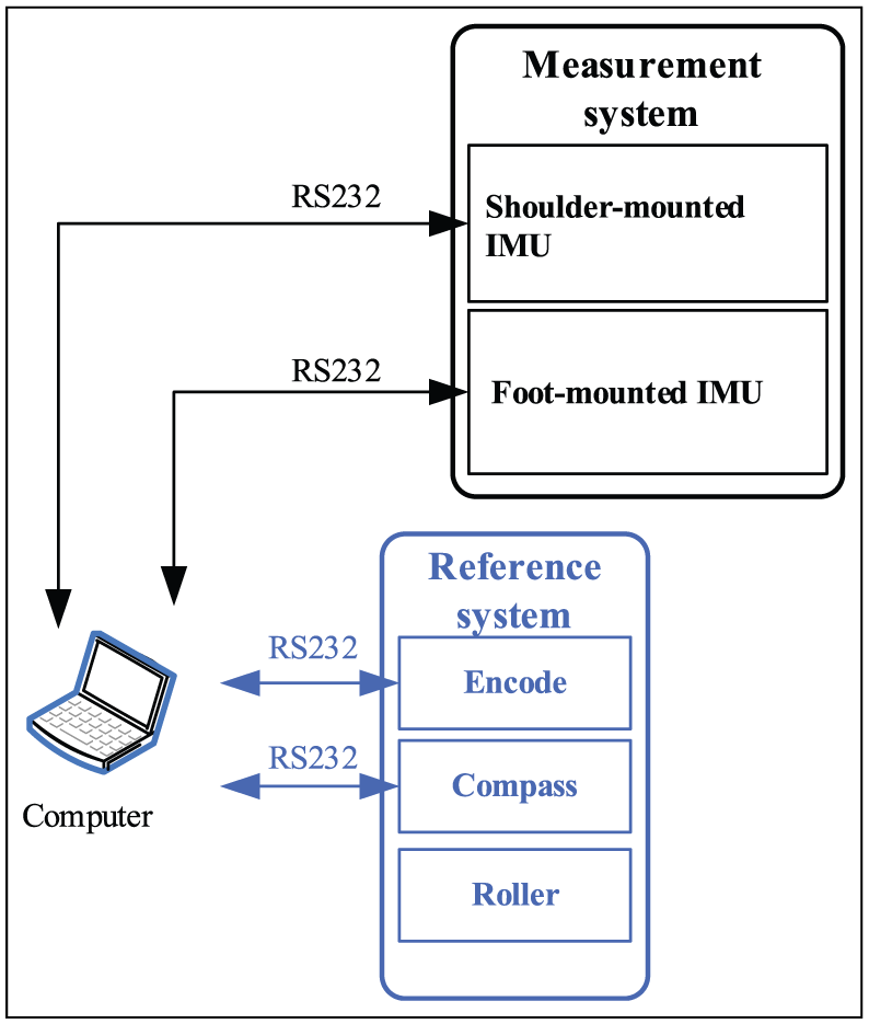
The architecture of the test platform. IMU: inertial measurement unit.
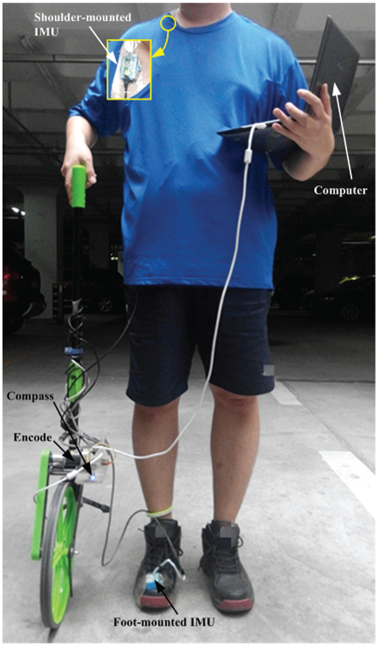
The prototype of the test platform.
4.2. Gait detection
For the gait detection, many proposed algorithms just employ basic signal processing of accelerometers16,20 or gyroscopes. 21 In this work, in order to improve the robustness and real-time performance of the gait detection algorithm, we fuse the information of accelerometers and gyroscopes. To declare a foot as stationary, two conditions (C1 and C2) should be satisfied at the same time as follows.
(C1) The magnitude of the acceleration,

where
(C2) The magnitude of the gyroscope,

where
Because the two conditions should be satisfied simultaneously, a logical “AND” is used in this work, and the results of the proposed gait detection algorithm are shown in Figure 4.
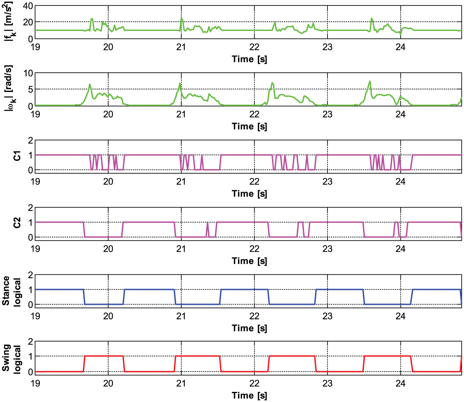
The results of the proposed gait detection algorithm.
4.3. Yaw measured from two IMUs
Figure 5 shows the yaw measured from the compass fixed on the bracket of the wheel, foot-mounted IMU, and shoulder-mounted IMU. The value from the compass is use as the reference value. From the figure, it can be easily seen that the yaw measured from the foot-mounted IMU has strong vibration compared with that from the shoulder-mounted IMU, and the yaw measured from the shoulder-mounted IMU is closer to the reference value. Thus, the shoulder-mounted IMU is used to correct the yaw error of the foot-mounted IMU in this work.
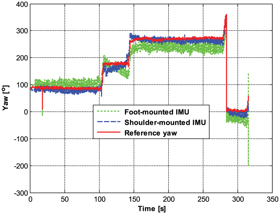
The yaw measured from the compass, foot-mounted inertial measurement unit (IMU), and shoulder-mounted IMU.
4.4. Position comparison between the single-mode method and the two-mode method
In this section, four methods are compared to assess the effectiveness of the proposed two-mode navigation method. Method 1 is the INS-only algorithm. In method 2, only the swing mode is used whether the person’s foot is in the stance phase or the swing phase. In method 3, only the stance mode is used in the whole course. In method 4, the proposed two-mode algorithm is used. In this work, a real test was carried out in the underground car park of Poly Garden, Jinan, China. The reference path is shown in Figure 6(d). In the test, we push the wheel and walk about 176 m, the test time is 312 s, and the velocity and the yaw of the wheel are selected as the reference value.
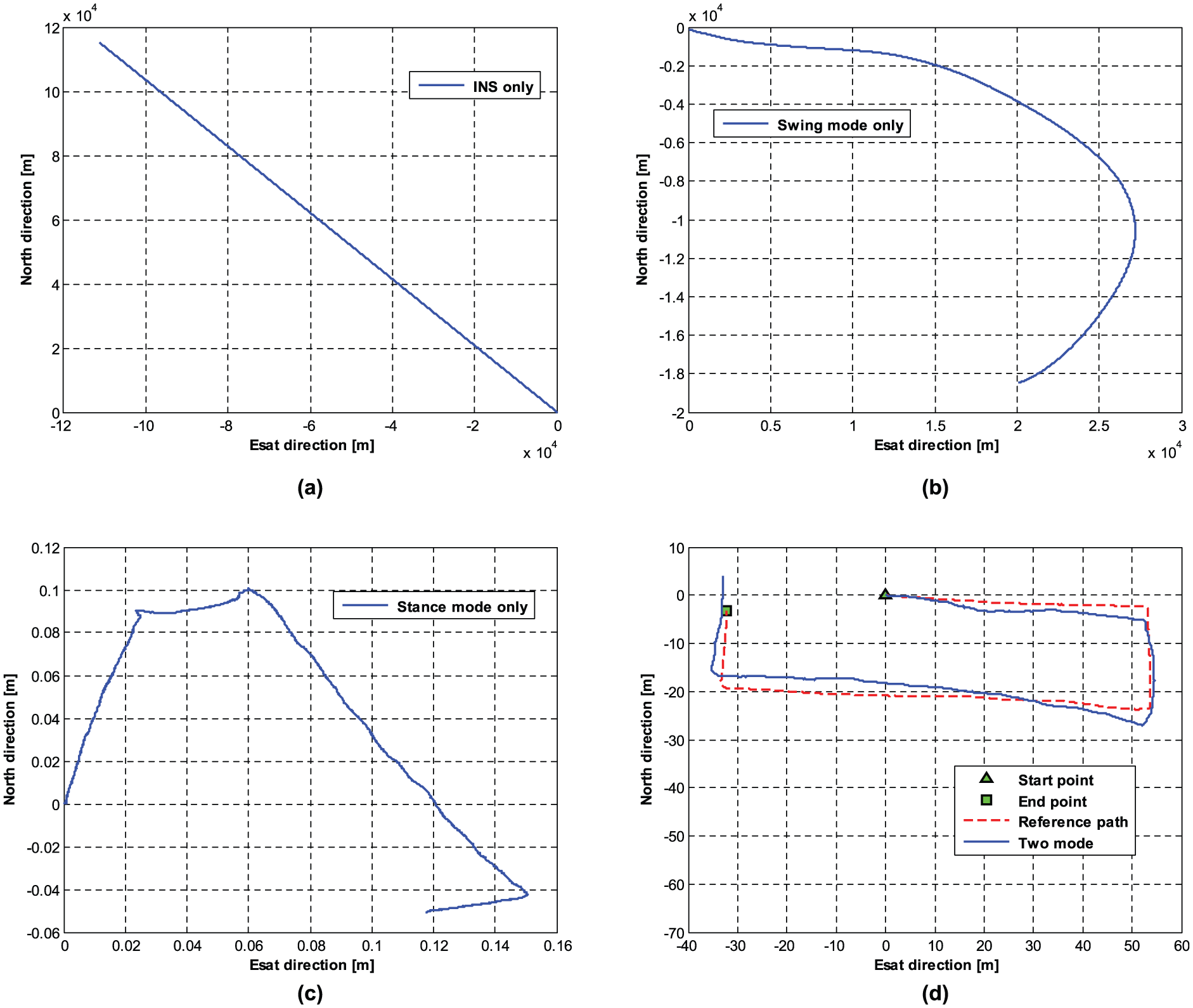
(a) The trajectory of the inertial navigation system (INS) only. (b) The trajectory of the swing mode only. (c) The trajectory of the stance mode only. (d) The trajectories of the zero-velocity update and ZARU and two-mode models.
Figure 6 shows the trajectories of the four methods. The trajectory of the INS-only algorithm is shown in Figure 6(a). From the figure, it can be seen that the INS position error grows quickly over time, which demonstrated that the INS cannot be used for long-time navigation. Figure 6(b) shows the trajectory of the swing mode only; similar to the INS-only mode, in this mode, the position error still accumulates with time since the position error is not able to be corrected directly. The trajectory of the stance mode only in the whole course is shown in Figure 6(c). Because this mode is considered for the condition when the person’s foot is stationary, the velocities and angular rates calculated by the foot-mounted IMU are used as the measurements of the velocity errors and the biases of the gyroscopes; the trajectory is almost in the original position. When the indoor PN works in two modes under difference conditions, the trajectory is shown as in Figure 6(d). It is evident from the figure that the proposed two-mode navigation method has good performance. When the person’s foot is in the stance phase, the stance mode is able to correct the velocity error, gyroscope drift, and the yaw error by using the measurements mentioned in Section 3.1. When the person’s foot is in the swing phase, the swing mode is used to correct the yaw by using the yaw error measurement. It can be seen that there are always some restrictions to the foot-mounted IMU when the person walks; thus, the trajectory is closer to the reference path compared with the other methods.
The comparison of the four methods in terms of position error is shown in Table 1. From the table, it can be seen that the proposed method has the smallest results compared with the other methods. Without any restrictions, the position error of the INS-only mode grows quickly; in this mode, the mean position root-mean-square error (RMSE) value of the east direction and north direction is 50,658.9007 m, which is not able to be used for indoor PN. In the method of the swing mode only, because the yaw is able to be corrected, which can improve the accuracy of the attitude transfer matrix, the mean position RMSE of the two directions reduces to 13,766.9164 m. In the method of the stance mode only, both the velocity error and the attitude error can be corrected; thus, the mean position RMSE reduces to 24.3843 m, which has a huge improvement compared with the swing mode only. However, it should be pointed out that in the swing mode only, some velocities and gyroscope drift when the person’s foot is in the swing phase are used as the error measurement for the KF, which is not suitable. Because the two-mode method contains two modes under two difference conditions, the mean position RMSE of the two-mode method is 1.9265 m, which is the smallest error compared with the other methods.
Comparison of the four methods in terms of position error.
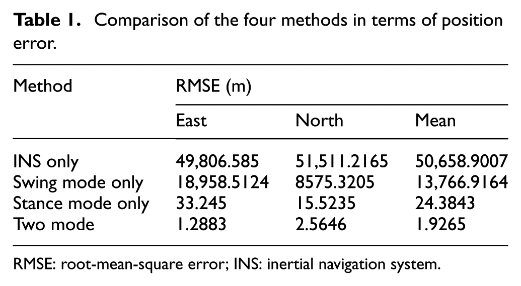
RMSE: root-mean-square error; INS: inertial navigation system.
4.5. Yaw comparison between INS only, stance mode only, swing mode only, and two-mode models
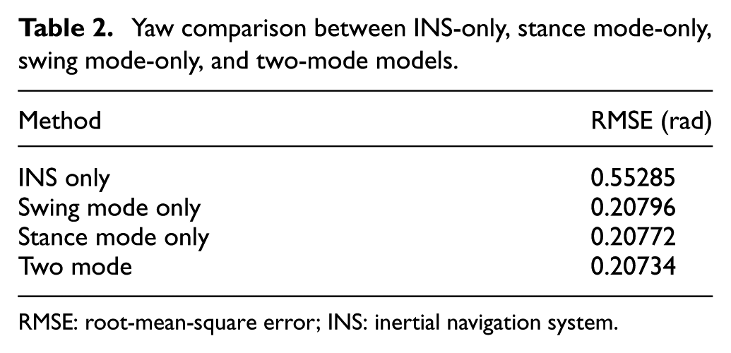
In this section, the performance between the methods mentioned above will be discussed. The yaw errors of the four methods are shown in Figure 7. From the figure, it can be seen obviously that the solutions of all methods do not have obvious drift because (1) the IMU used in this work contains a magnetometer and (2) the shoulder-mounted IMU is used to correct the yaw error of the foot-mounted IMU in this work. Moreover, the solutions of the swing mode only and the two-mode methods have smaller errors compared with the solutions of the INS-only mode and the stance mode only. From Table 2, it can be seen that the yaw RMSE of the INS-only method is 0.55285 rad, which cannot be used for indoor PN, because both the swing mode and stance mode have the yaw correction, and the yaw RMSE reduces to 0.20796 rad and 0.20772 rad. The proposed method has the smallest error compared with the other methods, and its yaw RMSE is 0.20734 rad, which can be used for PN.
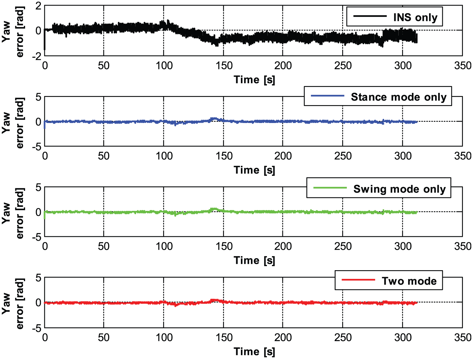
Yaw comparison between the methods mentioned above. INS: inertial navigation system.
Yaw comparison between INS-only, stance mode-only, swing mode-only, and two-mode models.
RMSE: root-mean-square error; INS: inertial navigation system.
4.6. Position error and yaw error comparison between two IMU-based ZUPT&ZARU (Zero Angular-Rate Update) and two-mode models
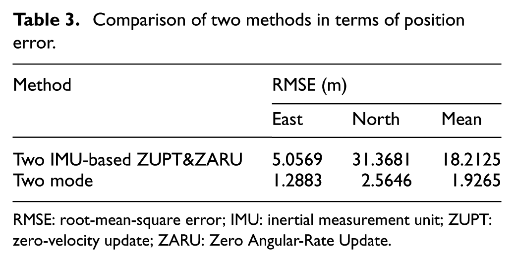
In this section, the performance comparison between two IMU-based ZUPT&ZARU and the proposed model is discussed. The two IMU-based ZUPT&ZARU is similar to the model proposed by Glanzer et al. 14 ; the difference is that the reference yaw value is provided by the shoulder-mounted IMU, not the foot-mounted IMU. The position error between the two models is shown in Figure 8. From the figures, we can see that the proposed model has the smaller error in the east direction and the north direction compared with the IMU-based ZUPT&ZARU model. From Table 3, it can be seen that the proposed model is effective to reduce the position error; it reduces the mean position RMSE from 18.2125 to 1.9265 m compared with the IMU-based ZUPT&ZARU model.
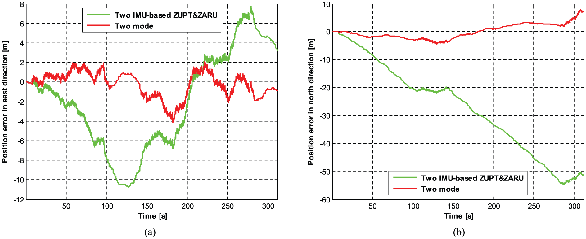
Position error comparison between two inertial measurement unit (IMU)-based zero-velocity update (ZUPT) and Zero Angular-Rate Update (ZARU) and two-mode models: (a) east direction; (b) north direction.
Comparison of two methods in terms of position error.
RMSE: root-mean-square error; IMU: inertial measurement unit; ZUPT: zero-velocity update; ZARU: Zero Angular-Rate Update.
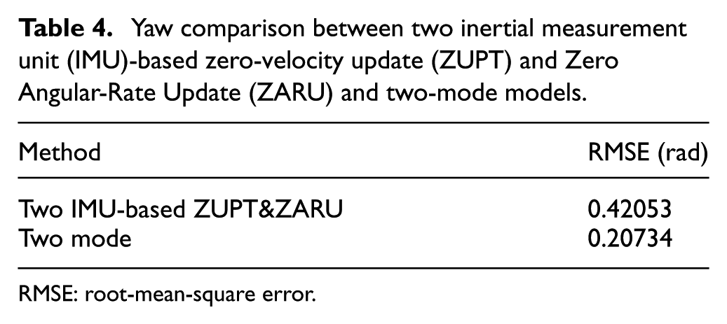
The yaw error between the two models is shown in Figure 9. From the figures, it can be seen that the proposed model is effective to reduce the yaw error by using the yaw correction in the whole course. Comparing with the IMU-based ZUPT&ZARU model, it has a smaller error. Table 4 shows that the proposed model is able to reduce the yaw error from 0.42053 rad to 0.20734 rad.
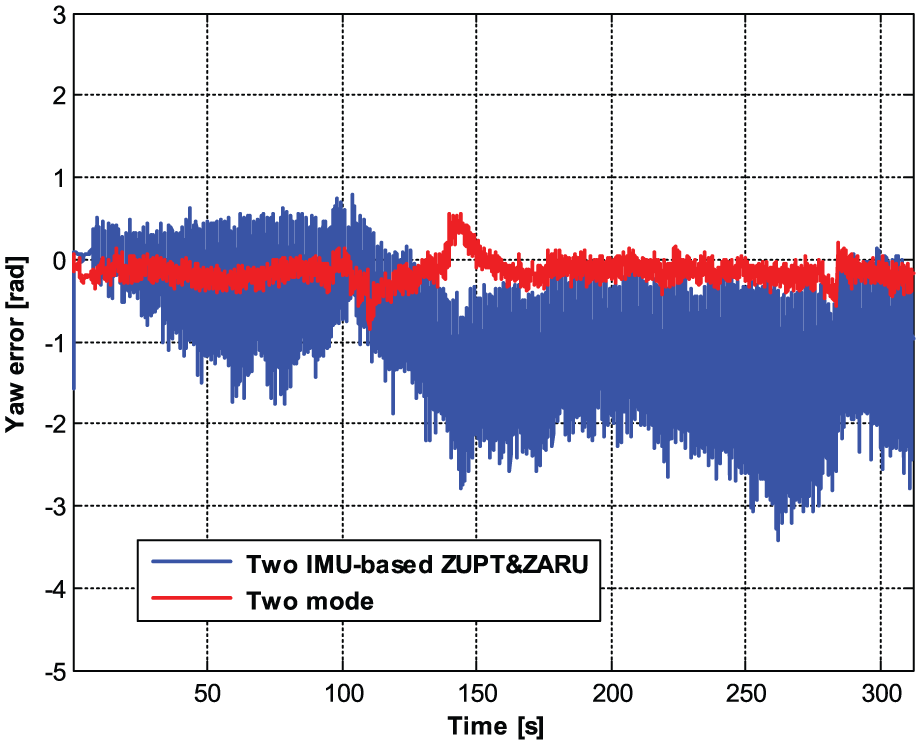
Yaw comparison between two inertial measurement unit (IMU)-based zero-velocity update (ZUPT) and Zero Angular-Rate Update (ZARU) and two-mode models.
Yaw comparison between two inertial measurement unit (IMU)-based zero-velocity update (ZUPT) and Zero Angular-Rate Update (ZARU) and two-mode models.
RMSE: root-mean-square error.
5. Conclusion
In this work, a two-mode navigation method for low-cost IMU-based indoor PN is studied. When the person’s foot is in a stance phase, the stance mode is used to correct the velocity error and yaw error. When the person’s foot is in a swing phase, the swing mode works and only the yaw error is able to be corrected. For verification, a real indoor test was done to assess the performance of the proposed two-mode method. The results show that the performance of the two-mode method is better than that of the single-mode method in accuracy.
Footnotes
Funding
This work was supported in part by National Natural Science Foundation of China (grant numbers 51375087, 41204025, 50975049), the Shandong Provincial Natural Science Foundation, China (grant numbers ZR2014FP010, ZR2015PE017), and the Doctoral Foundation of the University of Jinan (grant numbers XBS1503, XBS1501).