
Abstract
Driving simulation engines represent a cost effective solution for vehicle development, being employed for performing feasibility studies and tests failure and for assessing new functionalities. Nevertheless, they require geometrically accurate and realistic three-dimensional (3D) models in order to allow driver training. This paper presents the Automatic Ground Surface Reconstruction method, a framework that exploits 3D data acquired by Mobile Laser Scanning systems. They are particularly attractive due to their fast acquisition at the terrestrial level. Nevertheless, such a mobile acquisition introduces several constraints for the existing 3D surface reconstruction algorithms. The proposed surface modeling framework produces a regular surface and recovers sharp depth features within a scalable and detail-preserving framework. Experimental results on real data acquired in urban environments allow us to conclude on the effectiveness of the proposed method.
1 Introduction
Driving simulation engines require geometrically accurate and realistic three-dimensional (3D) models of urban environments. Nowadays, such 3D models are computed manually by graphic designers who combine a wide variety of data ranging from GPS car maps to aerial images, passing through Geographic Information Systems (GIS) data. 1 However, the resulting 3D models lack geometrical accuracy and photorealism, limiting therefore drivers training in real conditions. A more difficult task is represented by the road modeling process, as it requires very accurate geometrical information in order to supply driver perception for car maneuverability. In order to overcome the limitations of the existing 3D road modeling methods, several research projects 2 have been directed towards the use of Mobile Laser Scanning (MLS) systems, which allow sensing the environment of their surroundings with high sampling rates at high vehicle velocities. MLS systems provide geometrically accurate 3D measurements at the terrestrial level over large-scale distances. Nevertheless, such mobile acquisition results in a high amount of data that requires a fully automatic road surface reconstruction framework.
When dealing with the surface reconstruction problem using 3D point clouds acquired by MLS, several key issues must be addressed, such as ensuring scalability while preserving sharp depth changes and geometrical details, often sensible to smoothing operations.
The research work reported in this paper aims at exploiting 3D data acquired by a MLS system for automatic generation of geometrically accurate surface reconstruction in urban environments for driving simulation engines. In this paper, we propose a fully automatic surface reconstruction framework for roads and sidewalks that copes with the aforementioned constraints imposed by MLS systems, while fulfilling the requirements of driving simulation engines.
The paper is organized as following. Section 2 introduces our method for improving perceptive realism from 3D data acquired by MLS systems and the implementation of ground 3D models within the simulator software. The next two sections presents the existing solutions for ground surface reconstruction from 3D point clouds acquired by MLS. Section 5 provides an overview of our framework, which is driven by the ground segmentation module presented in Section 6. The ground points are exploited along with a novel surface reconstruction pipeline described in Section 7. Section 8 evaluates the performances of the proposed framework, while Section 9 presents quantitative results obtained over large-scale distances. Section 10 summarizes the obtained results and presents future extensions of our method.
2 Perceptive realism from three-dimensional point clouds acquired by Mobile Laser Scanning systems
Driving simulation engines represent a cost effective alternative for improving vehicle development with minimum costs. Such systems allow the simulation of a wide variety of traffic scenarios with visually enriched environments for developing vehicle dynamics, driving assistance systems, and car lighting.
2.1 Perceptive realism from scanned reality
Driving simulation engines fuse visual, audio, and motion senses within a global architecture composed of several modules. A detailed description of the functional structure of a simulator engine can be found in Bouchner and Novotny. 3 The spatio-temporal coherence in a driving simulation engine is a major concern. It is related to the proprioceptive integration, that is, humans’ sensibility to delay and perception incoherence (depth, motion).4,5 If they are not treated accordingly, they can lead to severe misperception, headaches, and accidents. A major concern in car manufacturing is represented by the use of realistic data and driving scenarios for designing adapted functional units. This requires consistent resources for collecting real-time traffic information such as vibrations, visual databases, sounds, and traffic incidents. As presented by Chapron and Colinot, 6 realistic restitution of longitudinal and lateral acceleration improves realism during driving simulation. A critical component in generating a suitable visual layer for driving simulation engines is represented by the realism of the 3D model, which must be correlated to both car vibrations 7 and the sound component.
2.2 Visual layer from MLS data
The use of GIS data within driving simulator engines provides an effective testbed for vehicle development. The visual layer is composed of two main ingredients: 3D environment models and the road network supplied by GIS datasets. Nowadays, such 3D models are created by graphic designers through the use of manual frameworks. In the presence of occlusions, missing data is filled with synthetic information extracted from similar non-occluded areas. Such workflows do not provide a real model, producing drivers’ misperception. In addition, continuous changes in urban planning require up-to-date 3D models and GIS datasets. This calls for automatic procedures capable of surveying and generating 3D models over large distances in a relatively short time. Furthermore, the cost for generating manually 3D models represents on average a third of the overall expenses required by a driving simulation engine.
2.3 From MLS data to scalable road networks via logical description
In order to overcome the fastidious processing of manual methods, the design of automated 3D modeling frameworks becomes a must. In addition, with the new advancements in mobile mapping systems (MMSs), it is now possible to acquire real data at the terrestrial level while driving in normal traffic conditions. This allows acquiring real data and generating 3D models over large distances within a cost effective methodology. Nevertheless, such a mobile acquisition results in a high amount of data that requires automated 3D modeling frameworks.
The workflow presented in this paper was developed within an ongoing research project, 2 which is focusing on the generation of geo-specific 3D models for driving simulation engines in order to allow vehicle design and driver training with minimal costs. The project is mainly concerned with the design of an automatic framework capable of generating geometrically accurate 3D models from MLS data acquired over large distances. The reconstructed ground surfaces generated by our algorithm are further exploited via a logical description for road networks encoded in different file formats, such as CityGML 8 or RoadXML, 9 accepted by driving simulation engines. They are widely employed to supply the software of driving simulation engines. A good example is SCANeRTM, 10 which provides a complete description of roads network for a variety of driving simulation engines.
3 Open issues for ground surface reconstruction from Mobile Laser Scanning datasets
MMSs equipped with active 3D sensors are well adapted for acquiring densely sampled 3D measurements of the underlying surface while driving in normal traffic conditions. Nevertheless, such a discrete representation must be further exploited in order to build a continuous surface through means of 3D modeling.
The existing surface reconstruction systems have reached a maturity level when dealing with stop-and-go mapping systems. However, when the input data is a 3D point cloud delivered by the latest MMSs, new key issues must be addressed in order to cope with several constraints, such as mobile acquisition, scalability, and detail-preserving capabilities, required for the surface reconstruction algorithms.
The mobile acquisition introduces new challenges to the existing surface reconstruction algorithms. They are represented by internal and external calibration steps, the accuracy of the sensor localization, and other parameters related to the acquisition (distance to the scanned surface, incident angle, surface geometry, etc.), which must be carefully identified and modeled correspondingly.
MMSs must be embedded with 3D modeling frameworks capable of scaling-up over large distances, while preserving geometrical details, such as sharp features and depth changes. This is required by the capacity to process large datasets in a fully automatic fashion and to design a consistent level of detail (LOD) for multi-resolution mapping of geo-specific 3D model databases. In addition, scalability issues must be addressed in order to deal with real-time rendering of large datasets acquired over large distances.
This paper is concerned with the ground surface reconstruction problem, which in man-made outdoor environments corresponds to the road, sidewalk, and ramp access areas. These are structured areas, including sharp depth changes and geometrical details, which need to be preserved in order to cope with the accuracy required by the visual layer of driving simulation engines. This requires noise smoothing procedures able to deal with MLS datasets in order to eliminate noise while preserving sharpness. This is an open issue that must be addressed in order to provide a highly accurate surface of road borders, ramp access, and other geometric details.
This paper presents a fully automatic algorithm designed for supplying ground surface reconstruction from MLS datasets. The proposed framework addresses the aforementioned constraints, being able to preserve geometric details, while being scalable over large distances.
4 State-of-the-art on ground surface reconstruction systems
Existing systems on ground surface reconstruction can be classified with respect to ground modeling and surface reconstruction algorithms. This section reviews the main methods belonging to each class.
Ground modeling systems proceed either by first building a mesh and then segmenting the ground from the mesh based on different criterions, or by first extracting the ground from the point cloud and then reconstruct the surface. In Carlberg et al., 11 the ground is segmented from the reconstructed mesh based on a proximity criterion applied over the triangles. In Wiemann et al., 12 the authors propose a ground modeling procedure for indoor environments that allows floor, wall, and ceiling segmentation based on the planar clustering procedure. The aforementioned methods proceed by meshing the entire point cloud, resulting in extra-time computation for reconstructing the non-ground objects and for eliminating them. When only the ground is required, it is more efficient to first extract the ground and then to build the mesh.
The ground surface reconstruction workflow presented in this paper separates first the ground from the non-ground objects and proceeds by reconstructing the 3D point cloud belonging to the ground. This allows one to apply adapted surface reconstruction frameworks consistent with planar (road, floor) or non-planar (complex) objects.
The state-of-the-art on ground modeling systems can be roughly classified in semi-automatic 13 and automatic frameworks. In Yu et al., 13 the authors introduce a high-resolution surface reconstruction algorithm for road areas selected by a human operator. While improving the state-of-the-art with a highly accurate ground reconstruction method, the proposed framework is not adapted for automatic processing over large-scale distances. Mesh-based methods reported by Carlberg et al. 11 and Jaakkola et al. 14 present the advantage of being automatic and thus are adapted for online data acquisition and processing over large distances. Nevertheless, several key issues of the existing techniques stand in the capability to reconstruct sharp depth features and geometrical details while being scalable over long distances.
The second main processing block required by a ground modeling system is represented by the surface reconstruction method for which reported frameworks can be classified in two major classes: implicit and explicit methods. The first class of algorithms15,16 proceed by polynomial fitting, while the second class17,18 reconstruct the surface by triangulating directly the 3D points, resulting in a surface very close to the acquired 3D point cloud.
In this research work we are interested in generating a triangular mesh as close as possible to the scanned surface and, thus, an explicit method is more adapted to our application. The results obtained are compared to two well known surface reconstruction methods belonging to each class: Poisson 19 and Greedy projection 20 techniques.
5 Overview of the Automatic Ground Surface Reconstruction algorithm
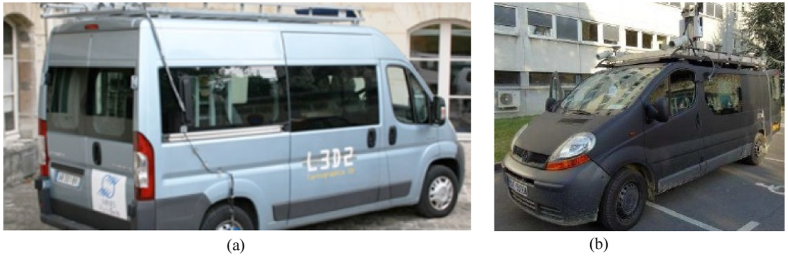
The proposed framework does not exploit any assumption for the acquisition setup, being therefore suitable for 3D point clouds acquired by a large variety of MMSs. 21 The algorithm presented in this paper was tested on various datasets supplied by two different MLS systems, which are illustrated in Figure 1. The proposed ground surface reconstruction algorithm comes together with a parallel scheme designed for supplying massive 3D point cloud processing acquired by MLS systems. Figure 2 depicts the global architecture of the Automatic Ground Surface Reconstruction (AGSR) method.
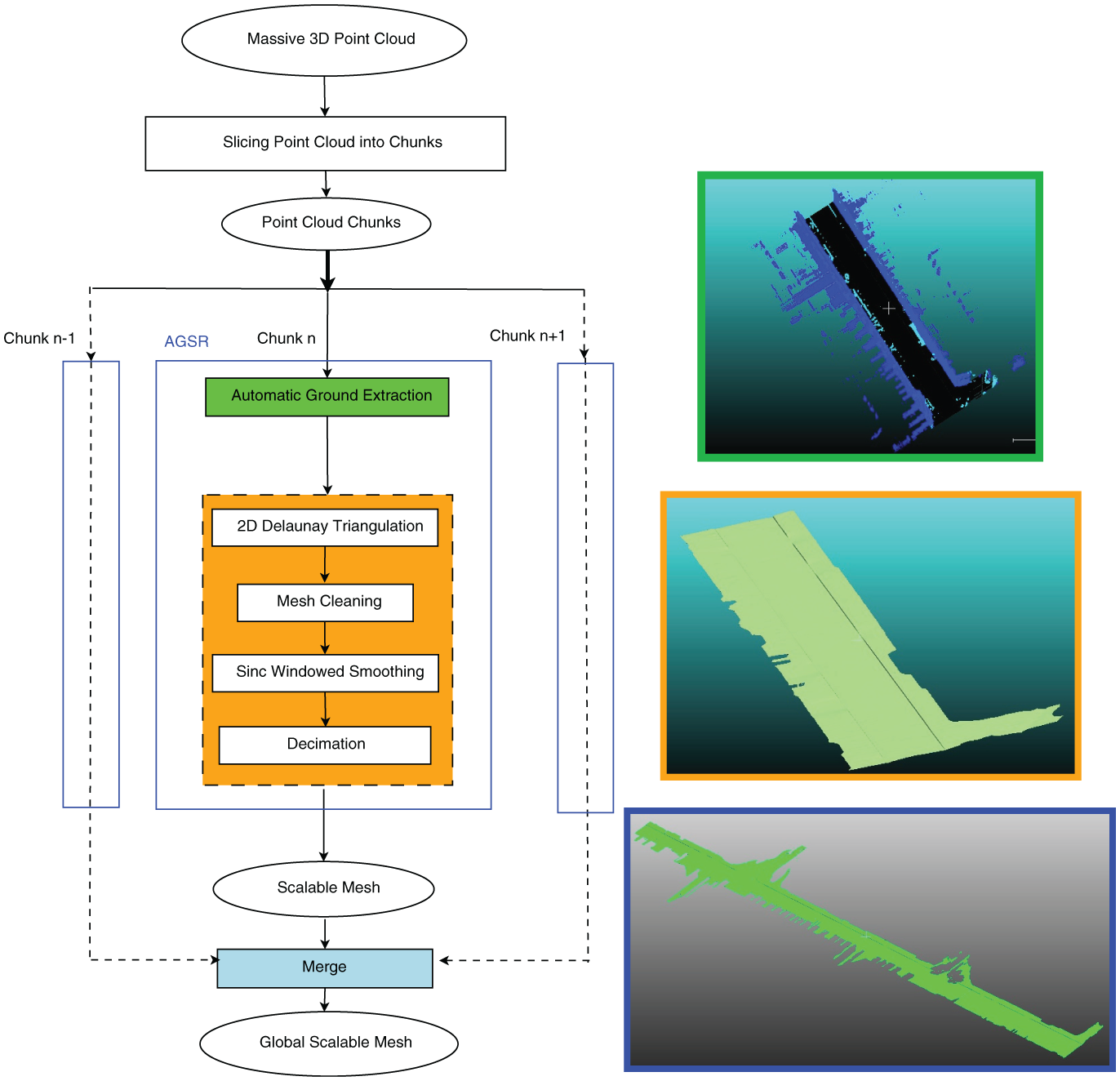
The global architecture of the Automatic Ground Surface Reconstruction (AGSR) method and its integration within a parallel computation scheme dedicated to massive three-dimensional (3D) point cloud processing. On the right-hand side are illustrated the outputs corresponding to three procedures composing the workflow: ground extraction – green; surface reconstruction – orange, merged decimated meshes – blue (color online only). 2D: two-dimensional.
The main input is a massive 3D point cloud that is first sliced into 3D chunks, with N Mpts (million points) per chunk. The length of a 3D chunk varies with the vehicle speed. Figure 3(a) shows an example of a 3D chunk extracted from a survey performed over an urban area located in Paris, France.
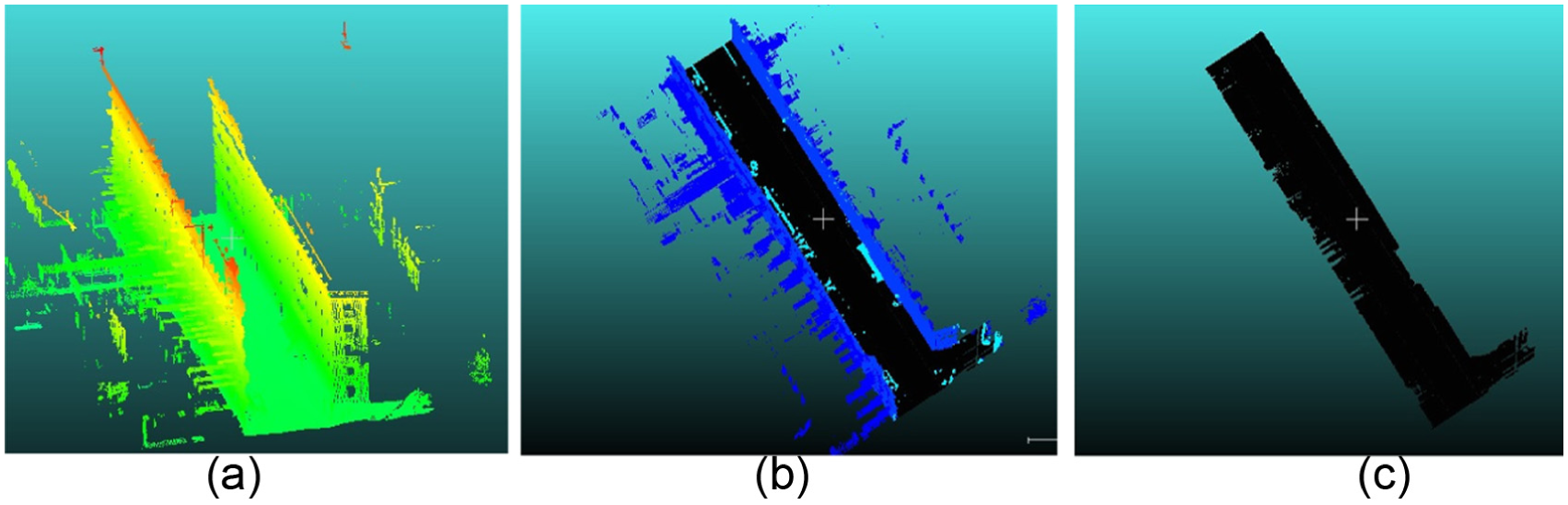
Ground extraction results: (a) example of a three-dimensional (3D) chunk acquired over Assas Road located in Paris (France): approximate length 82 m, with N = 3 Mpts, color coded with respect to elevation values; (b) 3D point cloud segmentation and classification results: facades – dark blue, road, sidewalks, and ramp access – black, non-ground objects – light blue; (c) the 3D point cloud corresponding to the ground: 1.27 Mpts. (Color online only.)
In this research work, the surface reconstruction method exploits a 3D point cloud segmentation and classification algorithm 22 for the ground extraction phase. This procedure assigns semantic labels to each 3D measurement, providing a classification output with different classes: ground (composed of the road, sidewalks, and ramp access), buildings, urban furniture, and cars. Such a semantic labeling scheme provides two advantages: (i) it gives the possibility to parallelize the surface reconstruction at the class level, while adapting the surface reconstruction method with respect to its geometric properties; (ii) in dynamic environments, when similar objects are detected, the already computed model can be inserted within a global reference scene.
The second phase of the algorithm exploits the 3D point cloud corresponding to the ground to build a triangular mesh. The algorithm starts by a planar Delaunay triangulation process, which is followed by a smoothing phase in order to reduce noise, thus generating a regular and drivable ground surface. In order to cope with scalability issues over large-scale distances, a decimation stage is applied to the smoothed mesh. In the final step, a global referential frame is updated with each mesh corresponding to each 3D chunk. The proposed workflow is designed to be applied in parallel to each 3D chunk. The following two sections are dedicated to a detailed description of the two main processing blocks of the AGSR framework: the automatic ground extraction step and the surface reconstruction phase.
6 Automatic ground extraction
This section describes the ground extraction procedure that represents the first step in the 3D modeling process. In this work we employ the segmentation algorithm proposed by Serna and Marcotegui. 22 It exploits elevation images along with Mathematical Morphology23,24 tools. The algorithm is composed of three processing blocks: the first one is dedicated to the projection of the 3D point cloud onto an elevation image. In the second step, ground and object segmentation is processed by analyzing discontinuities over the elevation images. Facade segmentation is performed by identifying highest vertical structures. The final procedure back-projects each pixel of the elevation image to the 3D space. Each 3D point is labeled, allowing one to recover 3D points corresponding to the ground.
Figure 3(b) presents the segmentation and classification result corresponding to the input point cloud depicted in Figure 3(a). Figure 3(c) depicts the 3D point cloud representing the ground composed of roads, sidewalks, and accessibility ramps. For a complete description of the 3D point cloud classification procedure, the reader may refer to Serna and Marcotegui. 22 The 3D points belonging to the ground are identified with respect to the labeling provided by the classification procedure and exploited along with the surface reconstruction process, which is described in the following section.
7 Automatic, scalable, and detail-preserving ground surface reconstruction
The ground surface reconstruction module transforms a 3D point cloud labeled as ground (illustrated in Figure 3(c)), into a continuous and scalable surface representation. The proposed framework is composed of several steps, which are illustrated in Figure 2 and described through the following sections. Firstly, the 3D point cloud representing the ground is triangulated in the (x, y) plane using a Delaunay triangulation algorithm, 25 which provides points connectivity. Then, we apply a mesh cleaning process to eliminate long triangles. In order to provide a continuous and regular surface model of the road, we apply the Sinc Windowed smoothing algorithm, 26 which eliminates high frequencies while preserving sharp depth features and avoiding surface shrinkage. In a final step, a progressive decimator27,28 is applied to the smoothed mesh in order to cope with scalability constraints when performing surface reconstruction over large-scale distances. The decimation phase provides surface representation with low memory usage, enabling efficient data transmission and visualization. In addition, the decimation procedure enables progressive rendering in order to deal with real-time constraints imposed by driving simulation engines.
7.1 Point cloud triangulation
Let us note with P = {xi, yi, zi |i = 1, …, Np} the 3D point cloud corresponding to the ground, where Np denotes the number of points. We apply the Triangle algorithm 25 to the 3D point cloud P to generate a planar constraint Delaunay triangulation with angles no smaller than 30°. Let us note with MDT the resulting ground mesh, which has Nt≈ 2Np triangles.
7.2 Long triangle elimination
In order to eliminate long triangles from non-uniform boundary points, we perform statistics over the edge lengths and identify those with maximum length, denoted emax. We identified that long edges correspond to emax≈δ
7.3 Building a regular surface
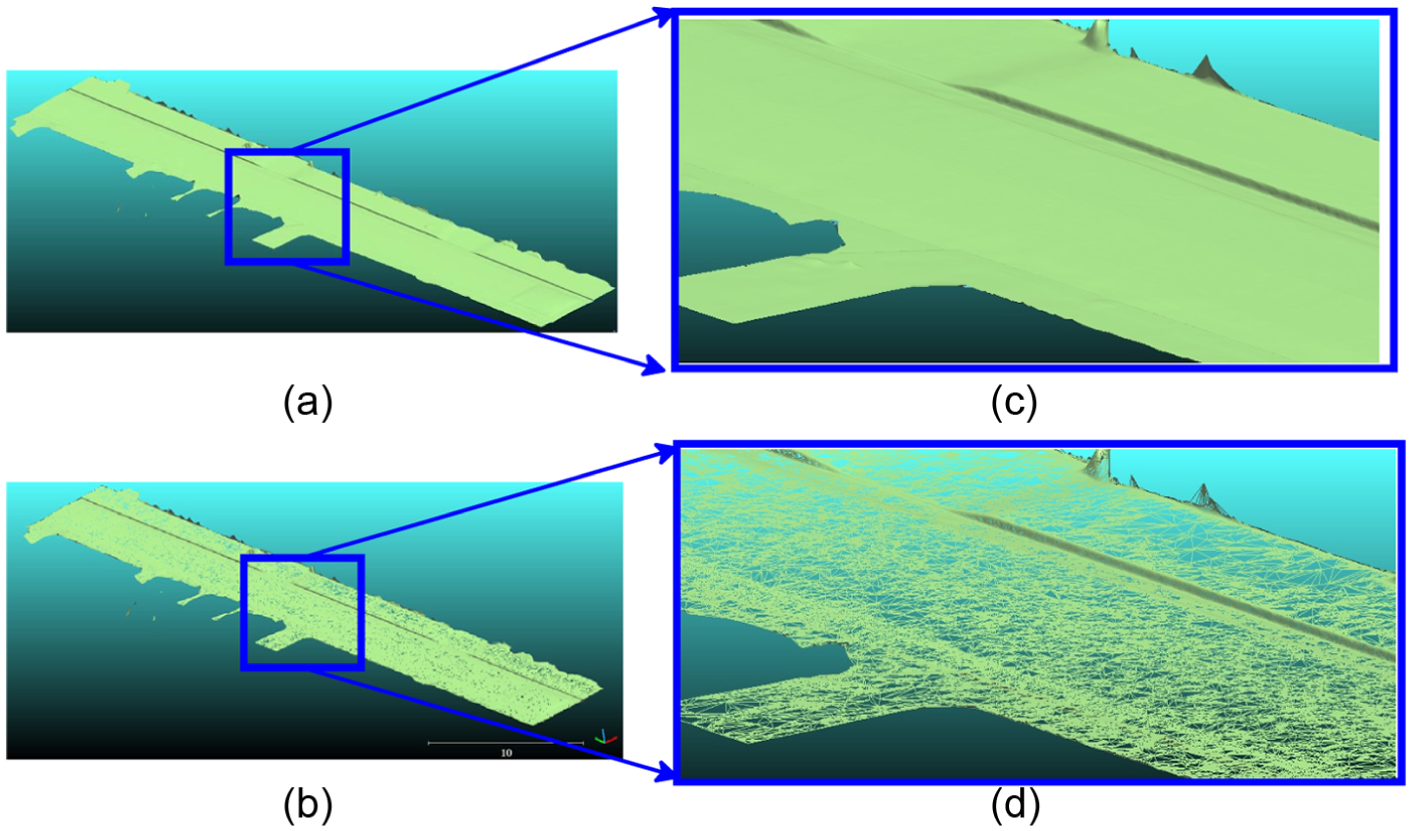
As illustrated in Figures 4(a) and (b), the triangulation of noisy 3D measurements results in high frequency peaks. Since we want to inject the ground surface model in driving simulator engines, an important issue that needs to be addressed is the geometrical accuracy. The 3D model must be distortion-free and regular. In order to obtain a regular surface, the Sinc Windowed smoothing procedure 26 is applied, which approximates low-pass filters by polyhedrons in order to eliminate high frequency peaks. Figures 4(c) and (d) illustrate the resulted smoothed mesh, denoted MS; it can be observed that the Sinc Windowed smoothing technique provides a regular surface while preserving roads and sidewalk border sharpness.
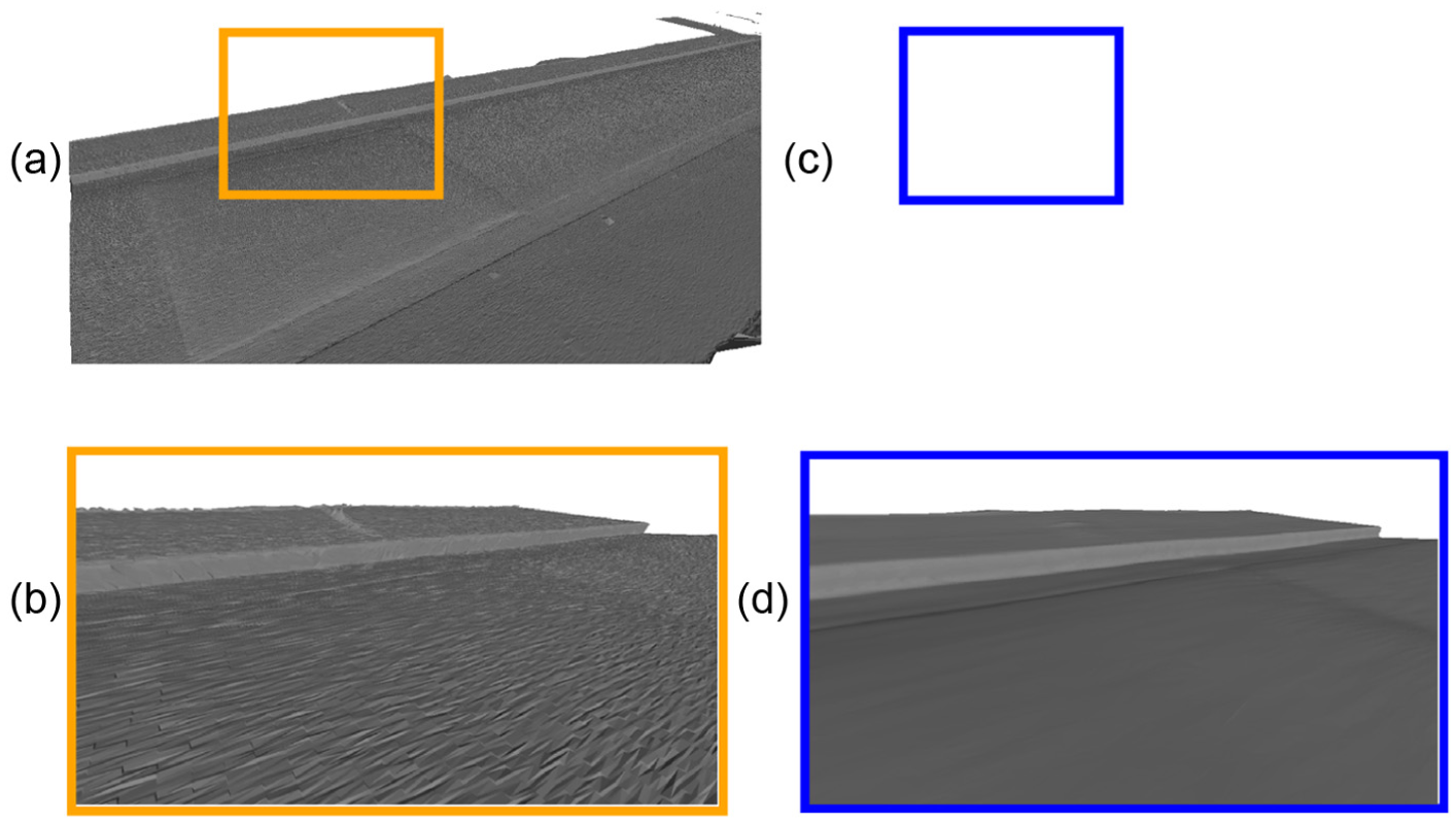
The result of the Sinc Windowed smoothing procedure 26 obtained on dataset Cassette acquired over the Cassette Road situated in Paris, France: (a) the output of the Delaunay triangulation procedure; (b) zoom-in view on the area selected in the rectangle illustrated in (a); (c) smoothed mesh output; (d) zoom-in view on the area selected in the blue rectangle illustrated in (c). (Color online only.)
7.4 Scalability
The smoothed mesh has a high number of triangles, being redundant and causing high memory usage. Moreover, in order to merge several mesh segments into a global scene, the mesh resolution must be drastically reduced. To this end, we apply the progressive decimation method,27,28 the main default implementation available in the VTK library. 31 The mesh resolution r(MD) is controlled by the reduction factor, denoted fD .
The algorithm proceeds as follows: firstly, each vertex is classified and inserted in a priority queue for further processing. The priority is set in order to minimize the distance to the original mesh caused by the vertex elimination and by the re-triangulation of the resulting hole. As stated by Schroeder et al., 27 following the vertex type (simple, interior, boundary, etc.), a different distance criterion is computed (distance to plane, distance to edge). Let us denote with MD the decimated mesh, and with N D the corresponding number of triangles.
Figure 5 illustrates the result obtained for the input point cloud depicted in Figure 3(c), reducing fD = 90% of the entire mesh. The remaining number of triangles corresponds to a mesh resolution of r(MD) = 10% of the original mesh.
The decimation results obtained for the dataset Assas: (a) smoothed mesh: Nt = 2.54 Mpts; (b) zoom-in view in of the area selected in the blue rectangle depicted in (a); (c) decimated mesh, wire-frame view: decimation factor fD = 90%, NtD : 254 kTriangles; (d) zoom-in view of the area selected by the blue rectangle illustrated in (c). (Color online only.)
It can be observed that the decimation algorithm preserves the reconstruction of the road, sidewalk borders, and accessibility ramps. In order to emphasize the detail-preserving capability of the decimation algorithm, Figure 6 illustrate the speed bump reconstruction after applying a maximal mesh reduction factor of fD = 90%.
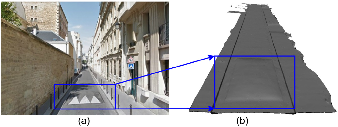
The final output of the proposed surface reconstruction method obtained on the dataset Cassette, with 51 m length: (a) Google Maps view of the surveyed area; (b) Np = 1.01 Mpts, Nt = 2.026 MTriangles, decimated mesh with fD = 90%, ND = 203 kTriangles.
7.4.1 Accuracy of the decimated mesh
As in Turnet and Zakhor, 32 we evaluate the accuracy of the decimated mesh by measuring the distance between the original point cloud P and the vertices of the decimated mesh, MD. We choose to compute the Hausdorff distance, 33 and we study both the mean and the root mean squared (RM SH) distances for different mesh resolutions r(MD). We observed that the mean is less sensible to the decimation process, while the RM SH varies with a higher amplitude, although it is negligible (±10−3 m). This let us conclude that the memory usage can be reduced by a maximal factor of fD = 90%, without sacrificing the accuracy of the model.
8 Performance evaluation
We evaluate the performances of the proposed framework in terms of accuracy, memory usage, and computation time.
8.1 Accuracy evaluation
We quantify the accuracy of the reconstructed surface with respect to several ground truth measurements that were performed manually on site (Cassette road, situated in Paris, France), mainly the height of the sidewalk border, the height of the access, and the road width, denoted Hsidewalk, Hramp, and Wroad, respectively. Table 1 illustrates the ground truth and the reconstructed dimensions for dataset Cassette (Urban ♯2) illustrated in Figure 6. It can be observed the reachable accuracy is better than 1.5 cm.
Accuracy evaluation of the ground surface reconstruction with respect to ground truth (GT) data for Urban ♯2, (acquired over Cassette Road situated in Paris, France), illustrated in Figure 6.

8.2 Computation time
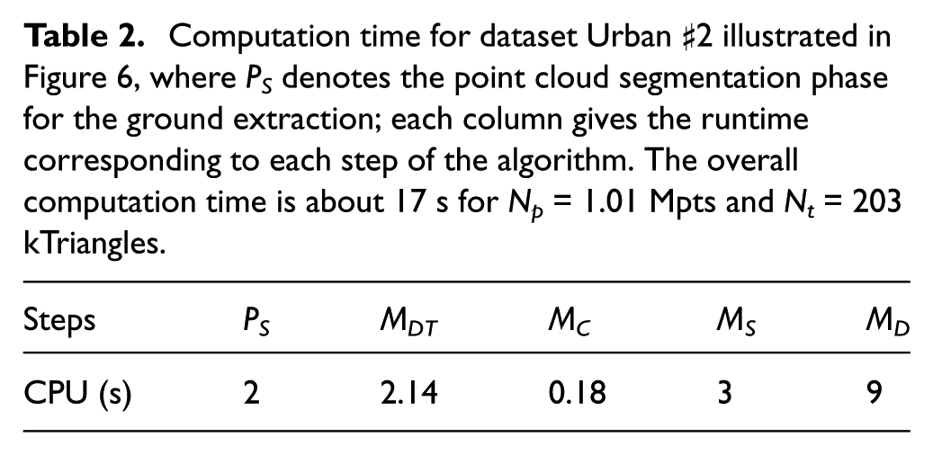
We evaluate our algorithm on a 64b Linux machine, equipped with 32 Gb of RAM memory and an Intel Core i7 running at 3.40 GHz. Our method is implemented in C/C++ and exploits PCL 34 and VTK 31 libraries. Table 2 illustrates the computation time obtained for the dataset Urban ♯2. We can observe that the decimation step is the most expensive phase, being related to the decimation factor fD. In this example, a maximum decimator factor was used fD = 90% for a mesh with 2 MTriangles, which results in 9 s of computation time.
Computation time for dataset Urban ♯2 illustrated in Figure 6, where PS denotes the point cloud segmentation phase for the ground extraction; each column gives the runtime corresponding to each step of the algorithm. The overall computation time is about 17 s for Np = 1.01 Mpts and Nt = 203 kTriangles.
8.3 Memory usage
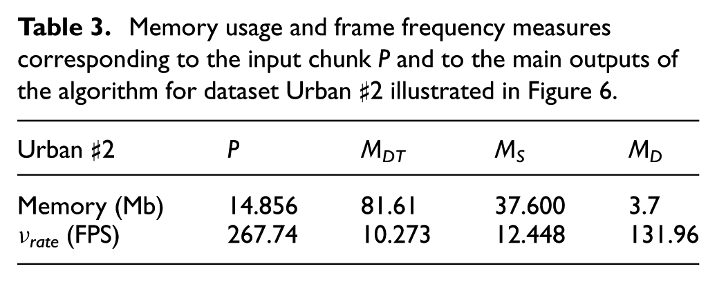
Table 3 illustrates the memory usage for each surface reconstruction step. It can be observed that the mesh representation is more efficient than the point-based one, allowing one to reduce the memory usage three times for the full resolution mesh and 20 times for a resolution mesh of r(MS ) = 10%. These results show that the proposed surface reconstruction framework provides a memory efficient surface representation while preserving geometric details.
Memory usage and frame frequency measures corresponding to the input chunk P and to the main outputs of the algorithm for dataset Urban ♯2 illustrated in Figure 6.
8.4 Visual rendering
The frame frequency, measured in frames per second (FPS), allows one to quantify the quality of a 3D model with respect to the visual rendering capability. The second row of Table 3 illustrates the frame frequency, denoted νrate and measured using Cloud Compare 35 for different surface representations (discrete and continuous). It can be observed that the point- based representation retains faster rendering capabilities than the full resolution mesh, which does not cope with real-time rendering requirements. In contrast, the decimated mesh exhibits real-time frame rates while providing a continuous surface representation.
Although the decimation step is the most computationally expensive processing block of the proposed surface reconstruction framework, it enables real-time rendering of a continuous surface over large-scale scenes while preserving geometric details.
8.5 Ground surface comparison
We evaluate the results of the proposed framework, entitled AGSR, with two well known surface reconstruction techniques. The first method is based on implicit functions, 19 while the second is an explicit method 20 that proceeds by a greedy projection. Figure 7 and Table 4 illustrate the results obtained by applying each reconstruction algorithm to the point cloud P corresponding to the ground depicted in Figure 3(c), acquired over Assas Road (Paris, France), denoted dataset Urban ♯1.
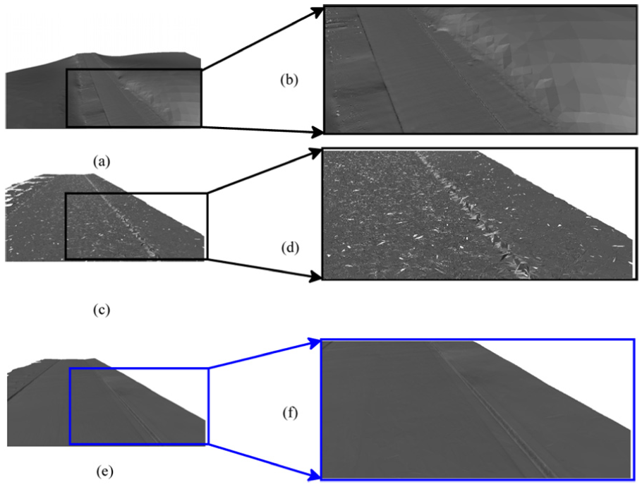
Comparison of surface reconstruction results obtained for the dataset Assas (Urban ♯1): (a) Poisson technique; (b) zoom-in view of the rectangular area selected in (a); (c) greedy projection technique; (d) zoom-in view of the rectangular area selected in (c); (e) proposed Automatic Ground Surface Reconstruction technique; (f ) zoom-in view of the rectangular area selected in (e).
Comparison between surface reconstruction methods; results obtained by running the algorithms on the dataset Urban ♯1 illustrated in Figure 3(c):
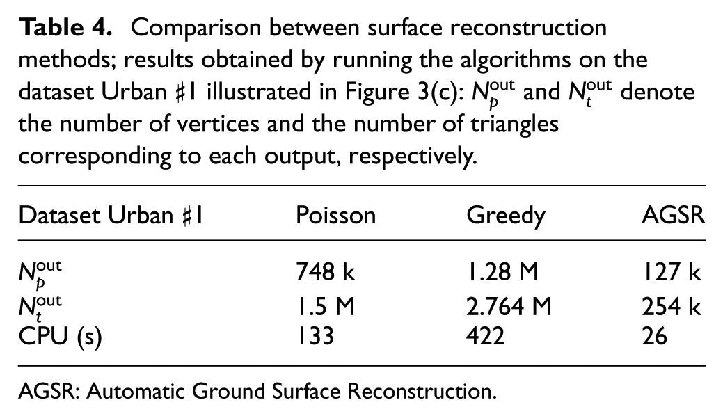
AGSR: Automatic Ground Surface Reconstruction.
By visually inspecting Figures 7(a) and (b), it can be observed that although the Poisson method provides a watertight surface, it results in mesh shrinkage around the sidewalk borders. Moreover, it reduces the number of points considerably, thus introducing inaccuracies between the point cloud geometry and the final surface. In contrast, the greedy projection method keeps all the measurements provided by the acquisition. Nevertheless, it results in discontinuity and high frequency peaks. The third row of Table 4 illustrates the computation time obtained using PCL 34 implementations. It can be observed that the proposed method increases the performances not only in terms of accuracy, as shown in Figure 7, but also in terms of computation time. More precisely, it allows one to decrease the runtime five times when compared to the Poisson method, and 16 times with respect to the greedy projection technique. Both methods, Poisson and greedy, are computationally expensive due to the normal computation step. When comparing the final results, it can be observed that although the proposed technique includes a computationally expensive decimation phase, beside the detail-preserving rendering capability, it features real-time surface reconstruction on parallel processing units.
9 Scaling-up detail-preserved three-dimensional ground meshes
The proposed surface reconstructed algorithm was tested on several datasets acquired by two different MMSs: Stereopolis 29 and L3D2 30 equipped with Riegl and Velodyne sensing devices, respectively. Following the 3D sensor device, different smoothing parameters were used.
Two examples of the surface reconstruction result obtained for several datasets are depicted in Figure 8. For the dataset Cassette, for computation time for one chunk with 3 Mpts acquired along 50 m, the algorithm performs the surface reconstruction in about 17 s. For 100 chunks, the algorithm processes 100 Mpts representing the ground in about 28 min. When applied to long-distance surveys, for 100 km non-stop driving and data acquisition, the MMS acquires six billion points and the ground surface reconstruction can be computed in about 10 h. In this research work, we focus mainly on providing an accurate and scalable surface reconstruction algorithm, time scalability being beyond the scope of the paper. Nevertheless, an upgrade of computational resources by a factor of 10 results in real-time surface reconstruction capabilities. When such an upgrading scheme is adopted, the algorithm can deliver the entire road network for 10,000 km length in about 5 days, non-stop driving, data acquisition, and processing at 90 km/h.
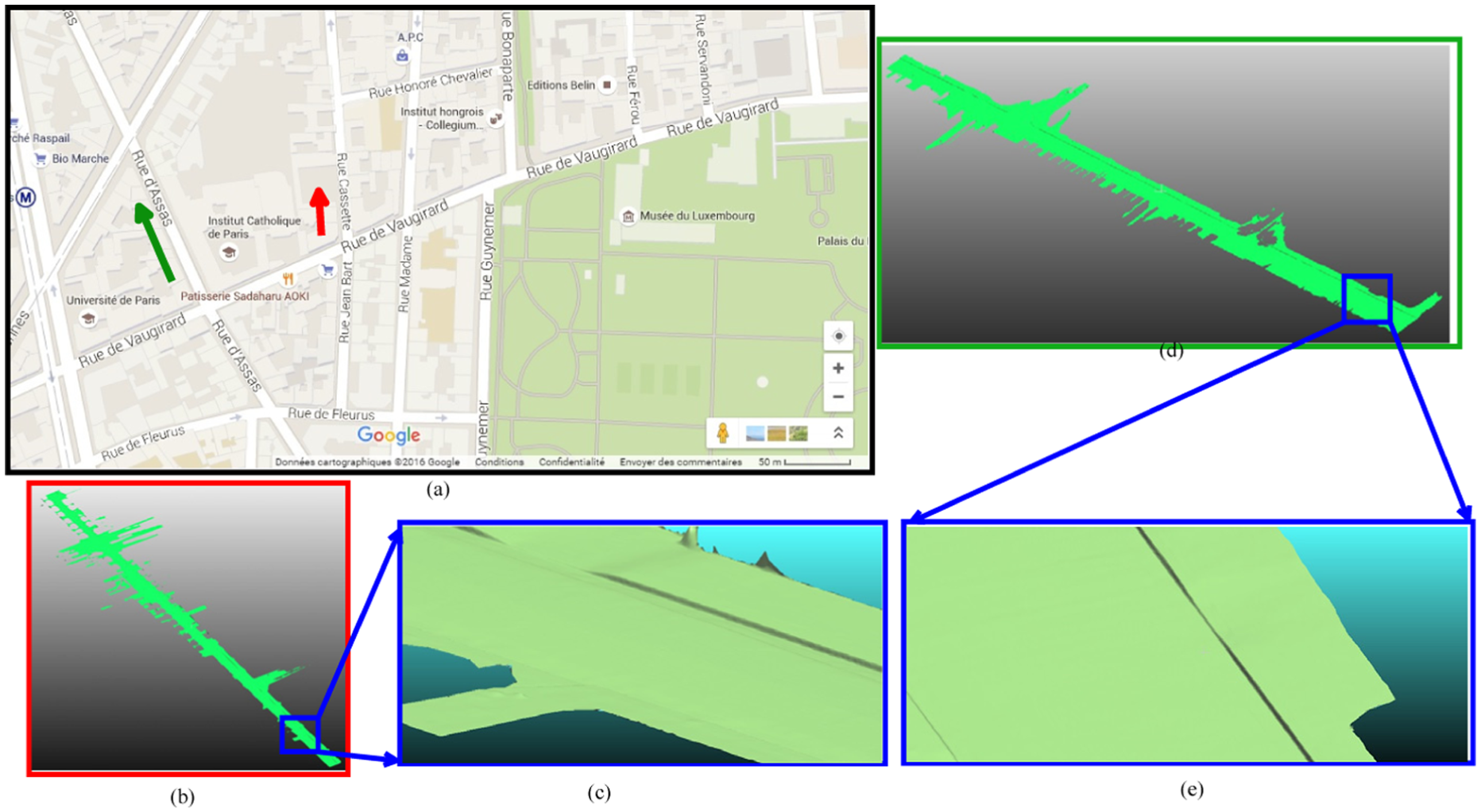
Surface reconstruction results obtained for several datasets: (a) Google Maps view of two areas surveyed by the Sterepolis mobile mapping system: Assas Road (Paris, France) – indicated by the green arrow, Cassette Road (Paris, France) – indicated by the red arrow; (b) surface reconstruction results obtained for five scan segments, overall length: 319 m; (c) zoom-in view of the blue rectangular area presented in (b), illustrating the accuracy of the reconstructed ramp access and sidewalks; (d) surface reconstruction results obtained for four chunks, overall length: 217 m; (e) zoom-in view of the blue rectangular area presented in (d), illustrating the accuracy of the reconstructed ramp access and sidewalks. (Color online only.)
10 Conclusions and research perspectives
The present research work introduces the AGSR algorithm designed to supply scalable and detail-preserving ground surface reconstruction in a fully automatic fashion. The proposed technique generates accurate 3D models of outdoor environments adapted for the driving simulator engine or for being embedded onboard mobile platforms for autonomous navigation applications.
The reported technique addresses several open issues of the currently existing surface reconstruction techniques, such as accurate reconstruction of sharp depth features in the presence of noisy datasets, scalability, and memory usage.
Research perspectives of the present research work are focusing on the photorealist surface reconstruction problem through the joint use of laser reflectance and RGB cameras. A second research perspective is related to the facade surface reconstruction and ground–facade merging within a global referential frame.
Footnotes
Funding
The presented research work is funded by the SIMVIR [2] project.