
Abstract
A finite element-based simulation was carried out to investigate the effects of friction-induced thermal load on rail under varied wheel slip conditions. The surface temperature rise from six different percentage slips (1%, 1.5%, 2%, 5%, 8.5%, and 10%) at the contact interface was examined for eight-wheel pass. The residual stresses and accumulated plastic strains evolved by the effect of localized temperature rise are estimated. Analytical formulation for conduction mode of heat transfer at the contact patch is used to estimate the temperature distribution. The interaction of thermal-elastic-plastic field conditions is obtained by a proposed simulation model. This is implemented in commercial finite element software ANSYS 14.0. In order to capture the steep thermal gradient beneath the contact surface, refined mesh is used in the upper layers up to a depth of 2 mm of the simulation domain. For better manifestation of thermally affected material layers, a temperature dependent bilinear-kinematic hardening material condition is applied. Results indicate the maximum temperature rise at about 0.6a from the trailing end in the contact ellipse of semi-major axis a. At higher slippage conditions the initial pearlitic rail steel gets converted to martensite which is often observed on rail surface as white etching layer known to be associated with rolling contact fatigue. The study reveals the mechanisms of thermally induced defects observable on rail surface. The outcomes, in addition, can provide useful information for the development of thermo-mechanically superior rail steels.
Keywords
1. Introduction
The rail–wheel system operation utilizes friction to transmit power. These friction/traction forces generate heat due to changes in relative slip between the contacting wheel–rail surfaces. Rise in temperature over the contact region is of critical importance to understand the accompanying queries. It can lead to material softening, 1 together with deterioration of rail–wheel profiles by promoting plastic flow in the material. 2 This may help initiate crack and subsequent propagation in either of the contacting elements.3–5 Often wheel slip protection systems are used to control the available traction and minimize slippage. Variation in speed and braking schedule are common the in rail-operation process. All these cause changes in the contact stress distribution. Further, variations in environmental conditions and track irregularities make the involved contact phenomenon more complex. Slip between wheel and rail for even a fraction of a second can intensify heat at the tiny rail–wheel material volume surrounding the touching region to several hundred degrees. Existing conditions develop a thermal state sufficient to produce observable damage on the rail in the form of rail burn, white etching layer (WEL), etc. These are localized metallurgical transformations over a small material volume. With the progress of time and subsequent rail-pass this damage gives rise to easy crack formation or corrosion cracking (see Figures 1–3). The presence of such damage endangers the safety of the transport system in particular. Thus, it is imperative to study the effect of thermal load, arising from variation in train speed, braking, and traction modifications, on rail material response.
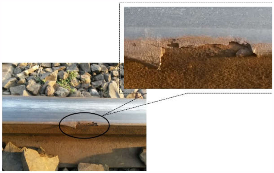
Rail edge damage due to thermal softening and accumulated material due to plastic flow at field end. Snapshot taken from around Dhanbad, India.
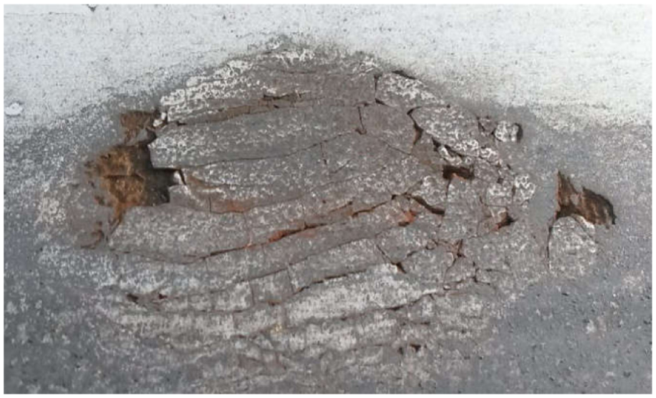
Rail surface damage due to martensite formation and disintegration by corrosion crack propagation. Snapshot taken from around Dhanbad, India.
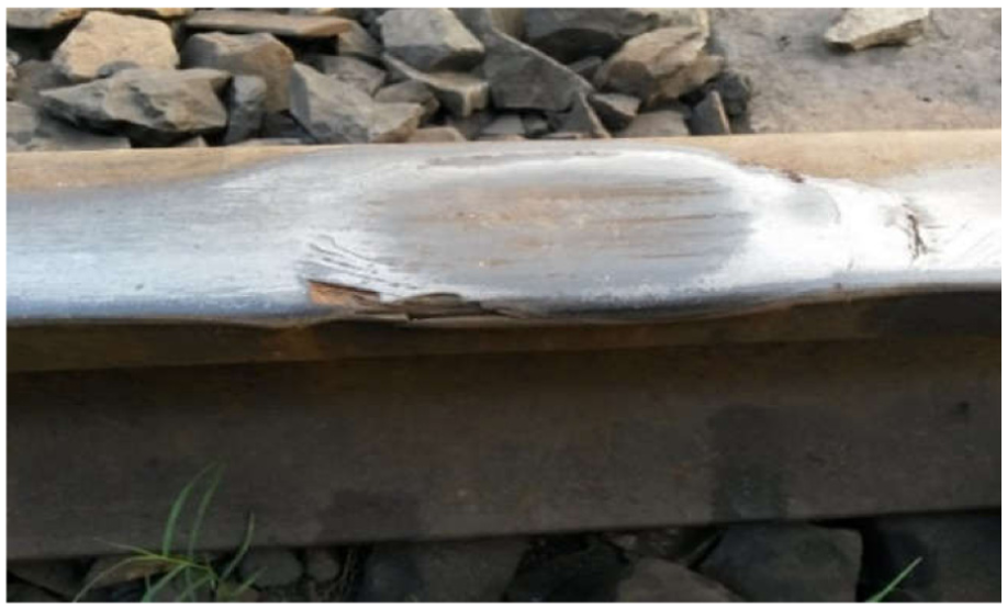
Rail burn at higher slippage. Snapshot taken from around Dhanbad, India.
A result of axle load transfer from wheel to rail is local elastic deformation over an elliptical area of contact. This contact zone embodies the stick and slip regions evolved from the velocity difference of the touching elements, shown in Figure 4. In the leading part of the contact ellipse forms the stick/adhesion zone while slip region appears at the trailing end. This slippage (occurring at the trailing end of the contact ellipse) is interchangeably called creepage or microslippage. Under varying traction and braking conditions microslippage occurs. In effect this increases the temperature of the dynamic wheel–rail contact interface by several 100 degrees kelvin. 6 The slip frequency increases significantly in the event of wheel lockup, hunting oscillations and in negotiating curved track/rail. With the increase in tractive force, the slip region increases reducing thereby the stick region. This results in a rolling-sliding contact condition. Once the tractive force reaches its saturation value, the stick region disappears, and the entire contact area turns into a state of pure sliding. Slippage variation at the wheel–rail interface increases due to improper track gradients, wrong driving practices (impulsive acceleration and braking), insufficient locomotive/traction power, and by contamination of the rail surface (like, oil, dust, dead leaves, etc.). All these can unfavorably reduce the available friction to an undesirable level that promotes skidding.

Rail–wheel contact mechanics showing contact zone, distribution of pressure, and shear stress over stick-slip region.
Moderate heat generation, evolved from the microslippage, in presence of a high-strain rate, induced by instantaneous increase in traction, often leads to the formation of shiny white surface on rail head popularly known as WEL. 7 Sudden braking raises the interface temperature impulsively to cause metallurgical transformation of the upper layer of rail head material’s microstructure, effective only to a film depth, from initial pearlite to martensite. The initial pearlite steel austenitizes at a favorable temperature to form a face centered cubic crystal structure that on rapid quenching further transforms to hard martensite of body centered tetragonal (BCT) crystal structure. 8 WEL is a martensite layer. During this conversion in the contact patch material, a volume expansion of about 0.5% is observed that induce residual tensile thermal stresses. 9 These residual thermal stresses in combination with rolling contact load cycle can promote crack initiation in hard and brittle martensite.
Heat transfer at the dynamic wheel–rail contact interface is an instantaneous process. It is, therefore, difficult to capture the value of the instantaneous temperature rise of the dynamic wheel–rail interface through any conventional experimental process. Progress on estimation of frictional heating by rubbing surfaces has a long history. The surface heat accumulation by sliding may easily be transferred by conduction into sliding bodies one being almost at ambient temperature. This effect has been studied by many researchers using analytical and numerical methods.6,10–16 The problem of temperature rise due to sliding contact was pioneered by Jaeger and coworkers and by Blok.17–20 Jaeger stated his theory on the frictional heating from rubbing surfaces, assuming that steady-state temperatures are achieved rapidly in the slider and most of the heat generated enter the stationary half of the contacting surfaces. Blok proposed highest temperature to develop at the sliding interface and specified it as flash temperature. The mathematical formulation with minor modifications is used to date to tackle contact (wheel–rail) problems.17–20 A detailed review in this respect was provided by Srivastava et al. 21
Tanvir approximated a fast moving heat source as an instantaneous static source and estimated the rise in temperature due to wheel slip on rail using the Laplace transform method. 6 Knothe and Liebelt analyzed contact temperatures for components in relative sliding motion combining Laplace transforms and Green’s function methods. 22 They identified that thermal stresses greatly affect the shakedown limit, expressed as the maximum contact pressure Po at the onset of yielding in the presence of residual stresses in wheel–rail contact. Fischer et al., 23 who extended the work of Knothe and Liebelt, 22 presented thermal stresses for frictional contact in wheel–rail systems. Ahlström and Karlsson described a one-dimensional analytical model of heat conduction for the thermally affected zone formed during railway wheel skid. 12 Sawley estimated the temperature developed in the sliding wheel and discussed the consequences of the rate of change of temperature on metallurgical means of avoiding spall type defect formation. 24 Gupta et al. used the finite element method to estimate the frictional heat across the contact patch for different combinations of creep and adhesion. 13 Widiyarta et al. proposed a computer model to simulate and predict wear and crack initiation in rails induced by thermal effects leading to ratchetting failure. 16 They predict frictional heating to increase the rate of damage accumulation by ratchetting.
The presence of damaged rails, caused by thermal stress, imparts noise, premature rail replacement, enhances the possibility of damage on wheels rolling on it, and has the potential to cause derailment. Thus, an assessment of the thermal response of rail material induced by variation in microslippage incorporated by different wheel slip percentage promises to be a very important way to understand different damage mechanisms occurring at the rail surface. An analytical solution limits its applicability only for idealized geometry and material parameters. Numerical simulation, on the other hand, is more versatile than analytical methods in terms of adaptability of varying material properties and wheel–rail geometry combinations. In this paper, a two-dimensional thermo-elasto-plastic finite element model of a rail section is used in the ANSYS 14.0 platform to simulate the problem. Six different slip percentages and up to eight wheel-pass conditions are considered to determine their effect on temperature distribution across the contact zone of rail section, residual thermal stress distribution, and the accumulated plastic strain developed therein.
The main objective of this study is to explore and expose the influence of thermal load in developing rail-surface damages and their possible range of penetration. The results from this study clarify the influence of slip percentage on temperature rise, thermal stress, and strain accumulation that will help to decide strategies for minimizing rail surface damage states. It may also be used to design contact surface materials to minimize maintenance and operating hazards on the basis of layers of materials being influenced by thermal effects.
2. Numerical modeling
The actual wheel–rail contact condition involves several loads acting simultaneously. These are dynamic load, impulsive load, together with traction and frictional load. These load systems are responsible for defect evolution mechanisms like material transformation, thermal softening, plastic deformation, and crack initiation and its propagation. The present study focuses on the effects of frictional heat introduced by varying slip percentages, thereby increasing the temperature level. Wheel slippage varies with the contact patch size, speed, curve tracking, and braking. This is the major source of temperature rise-induced thermal stresses in rail material. In the section to follow the analytical method for calculation of temperature rise is discussed. This formulation is used later for the finite element model validation.
2.1 Analytical method for calculating the temperature rise at the wheel–rail contact
Estimation of temperature rise in the contact region is an essential component in formulating the thermal stress evolved from microslippage. The major source of heat, in general, is considered to be the wheel temperature attained from a brake application condition and sink is the rail stock at ambient temperature. During rolling-sliding condition, on the other hand, the friction coefficient varies according to stick-slip zone distribution present. This, in turn, raises the temperature of the contact interface. The rail–wheel functional pattern introduces the contact dynamics that directs the heat transfer condition to be predominantly in conduction mode. Accordingly, the general heat transfer equation is used to govern the temperature field estimation in wheel–rail contact:
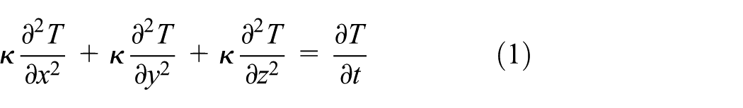
where x, y, z, and t are the spatial coordinates, T is temperature, and
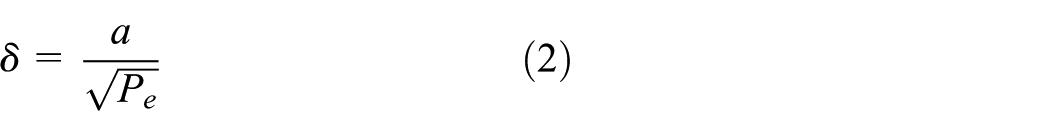
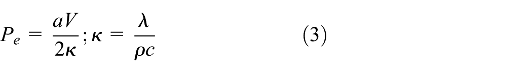
The wheel remains in contact with a location on the rail surface for a very short span of time. Frictional heat generated at the contact interface acts as a fast-moving heat source and the heat transfer is able only to affect a very thin layer of rail surface material. The thickness of the affected zone, termed as thermal penetration depth (δ), depends on the semi contact length (a) and the non-dimensional Peclet number (Pe) and is defined as follows:
The Peclet number is a function of the wheel/forward velocity (V) and the thermal diffusivity,
Ertz and Knothe suggested that for
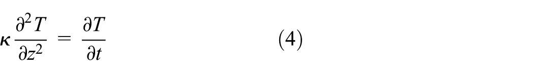
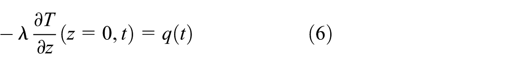
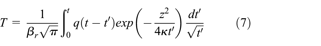
This second-order partial differential equation specifies the temperature to change with rail depth and time. A review of literature by the authors indicates that different methodologies can be adopted to solve this equation. 21 The approach of Ertz and Knothe for temperature estimation arising from pressure distribution on smooth surfaces is considered in this study and discussed here briefly. 10 The model follows a modified heat transfer relation given by Carslaw and Jaeger.17,18 The frictional contact pressure problem is treated to be a semi-infinite solid subjected to a moving heat source q(t) applied at a reference point on the surface, z = 0 at t≥ 0. The initial and boundary conditions for the Fourier heat conduction Equation (4) are as follows:

The general solution of Equation (4), shown by Carslaw and Jaeger, 17 is:
Ertz and Knothe modified this solution by introducing non-dimensional contact patch coordinates
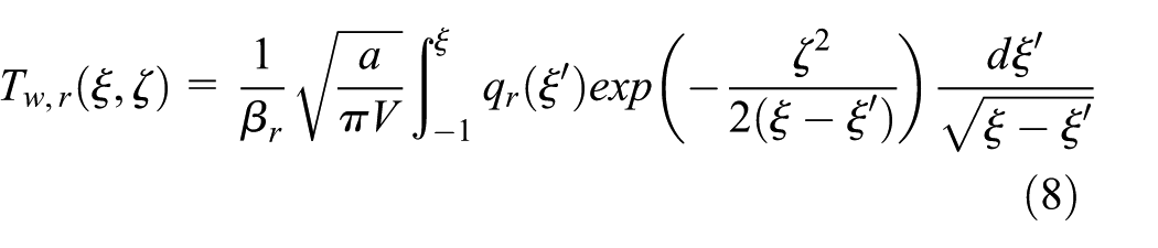
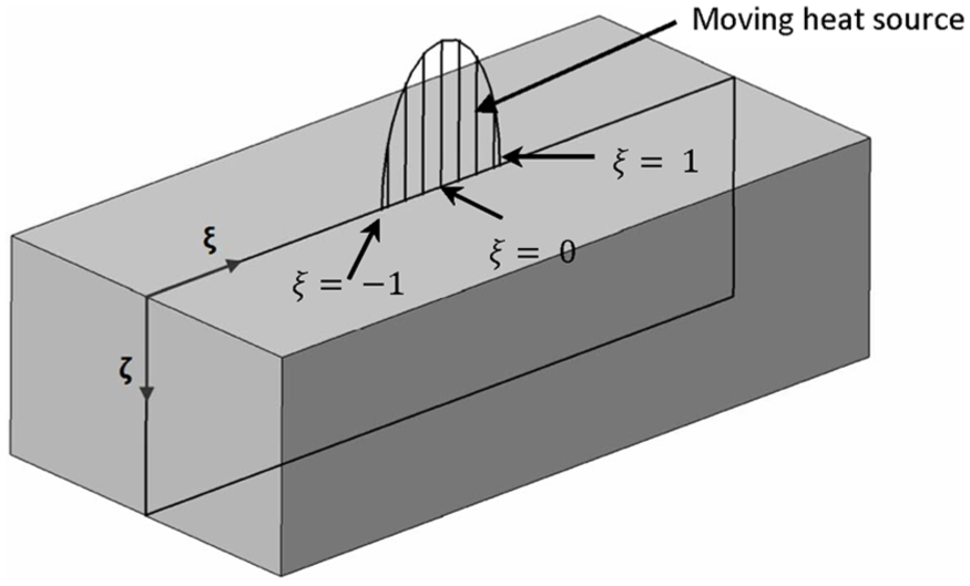
Non-dimensional coordinate system.
The analytical solution for this integral equation with constant heat flow rate qr at the rail surface (
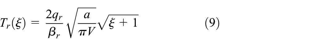
The result from this relation is used to validate the proposed finite element model.
3. Heat flux calculation
Hertzian contact theory, developed by Heinrich Hertz in 1882, considers two elastic nonconforming bodies. If pressed together the contact area assumes an elliptical shape with a semi-major axis a and semi-minor axis b. Similar is the condition in a rail–wheel contact. 25 The distribution of the contact pressure in this elliptical contact area is as follows:
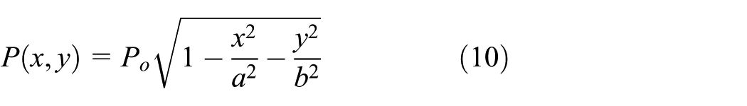
In the above,
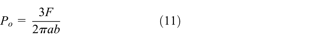
where F is the axle load. The semi-axes a and b can be obtained from the following:
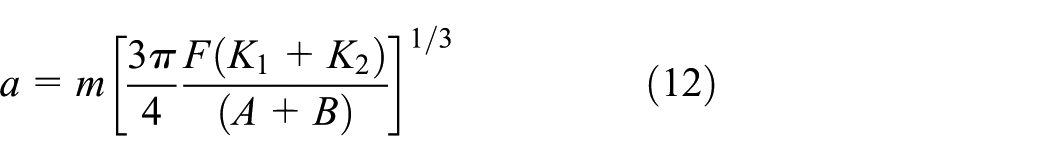
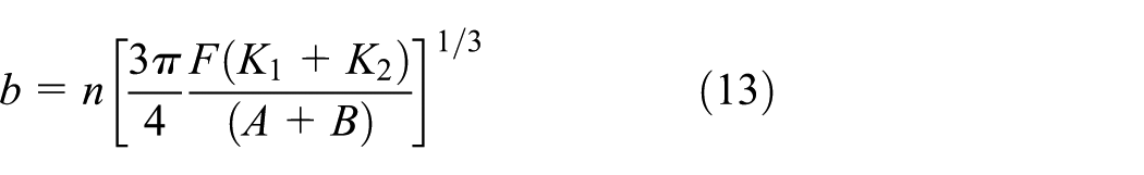
where K1 and K2 are constants given by

where µ is the coefficient of friction. During pure sliding condition, the heat flux rate


(a) Three-dimensional contact pressure distribution on Hertzian elliptical contact patch. (b) Simplified two-dimensional rail simulation domain taken from the middle of the rail section along the line of contact.
The nature and distribution of the evolved heat and the temperature fields at the interface are to satisfy thermodynamic equilibrium. For this, a heat partition factor, suggested previously,
21
is introduced to maintain the continuity of temperature and conservation of heat fluxes between the wheel and rail surfaces. In the present model, a constant heat partition factor (


while the total heat flux is given by:

4. Finite element model
Simulation of thermal effect due to percentage slip variation at wheel–rail contact is carried out for a 105 mm long rail segment. For all computations, vehicle running at a speed (V) of 90 km/h is considered. The semi-major axis (7.32 mm) of the contact stress ellipse is obtained from Hertz contact theory. Sequentially coupled thermal–structural stress analysis is adopted to obtain temperature field and associated thermal stresses across the wheel–rail contact interface by the model, as shown in Figure 7.
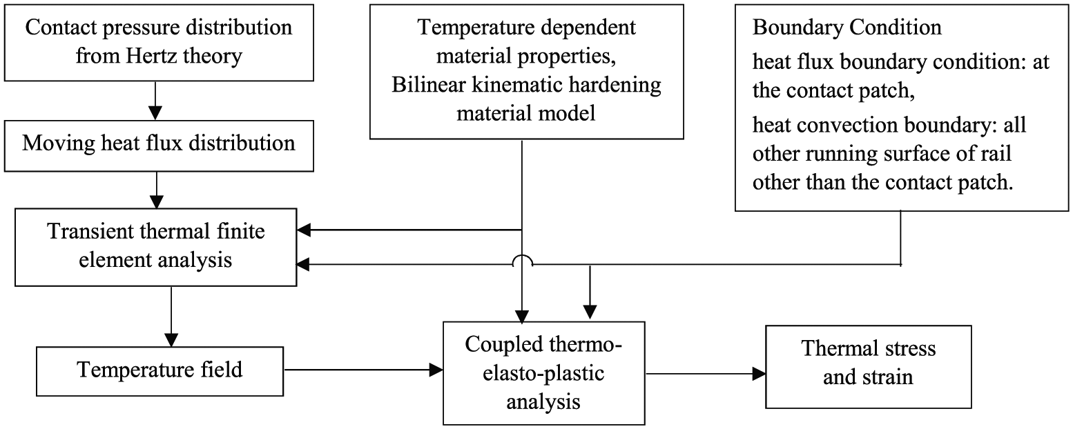
Finite element analysis model for the current simulation using ANSYS 14.0.
The heat flux distribution along the contact patch, shown in Figure 6(b), is translated on the rail surface for eight wheel passes. Rail surface other than the contact patch is subjected to convection mode of heat transfer. The heat transfer coefficient
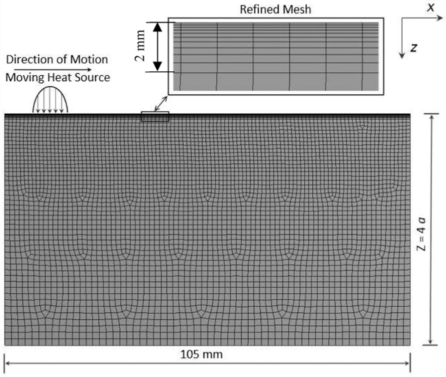
Two-dimensional finite element model for the problem domain.
5. Material model
A bilinear kinematic hardening material law is applied to simulate plasticity effect in the rail material. 30 For completeness of the presentation, the mechanics involved is briefly stated. The yield criterion has the form:

where

where the backstress

where G is elastic shear modulus and the shift strain is numerically integrated from the incremental plastic strain:
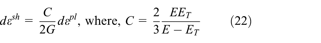
Here E is Young’s modulus and ET is the kinematic hardening parameter (also called tangent modulus or hardening modulus). The evolution of plastic strain can then be determined by the plastic flow rule:
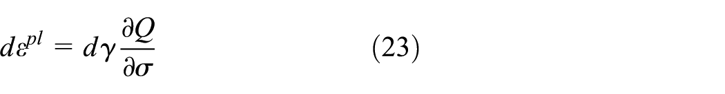
where
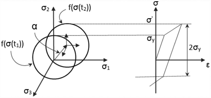
Stress–strain behavior of bilinear kinematic hardening material model.
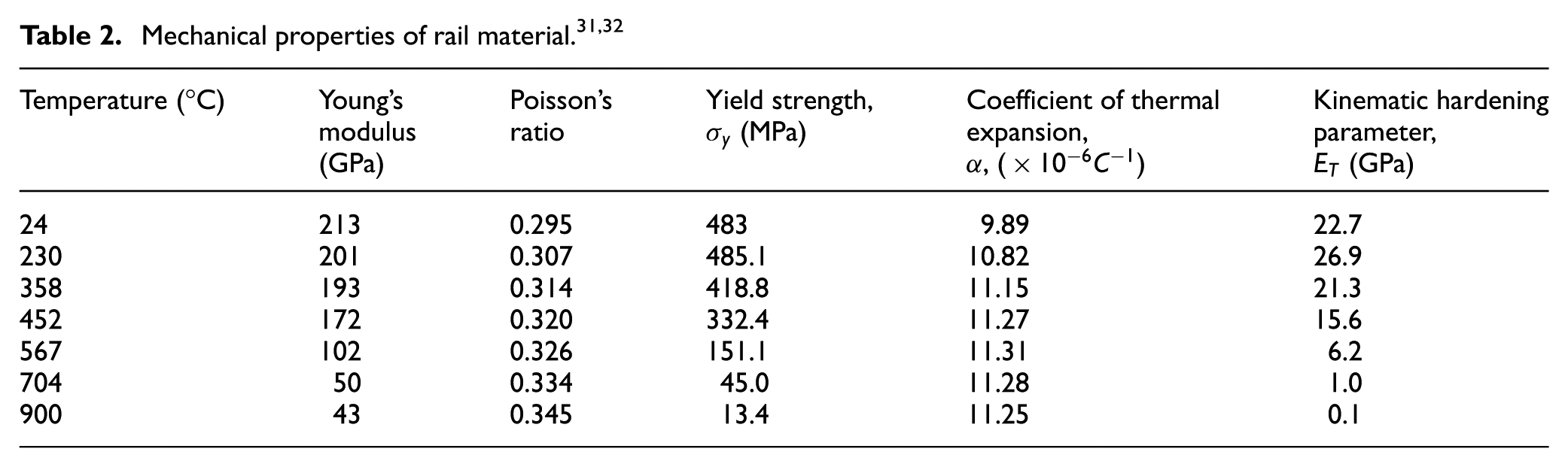
This material condition is used in the finite element model. Temperature-dependent thermal and mechanical properties are used for the rail material and the same are given in Tables 1 and 2, respectively.

6. Simulation cases
In order to simulate the contact conditions, six different slip rates are applied. The positions of the axles are shown in Figure 10. To obtain a more realistic manifestation of desired outputs, the frequency of loading over a contact region is applied in correspondence with wheel locations in Figure 10. The input parameters applied in the simulation are given in Table 3.
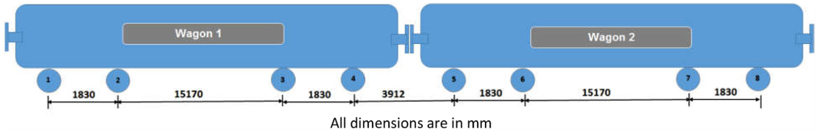
Schematic drawing for axle distance of the wagon used in the simulation.
Parameters used. 33
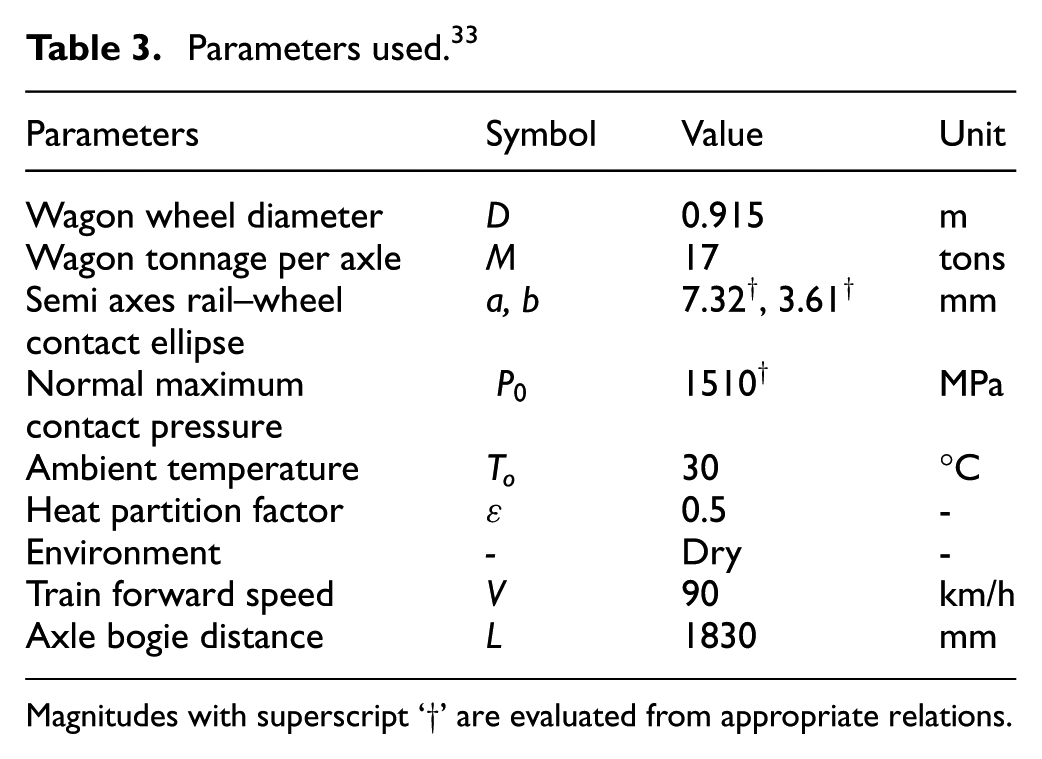
Magnitudes with superscript ‘†’ are evaluated from appropriate relations.
The friction coefficient and wheel sliding velocity acting along with the contact pressure (arising from axle load) produces the heat flux. This dynamic heat flux moves with contact location. Its schematic illustration is demonstrated in Figure 11 for a single wheel pass.

Schematic representation of wheel passes.
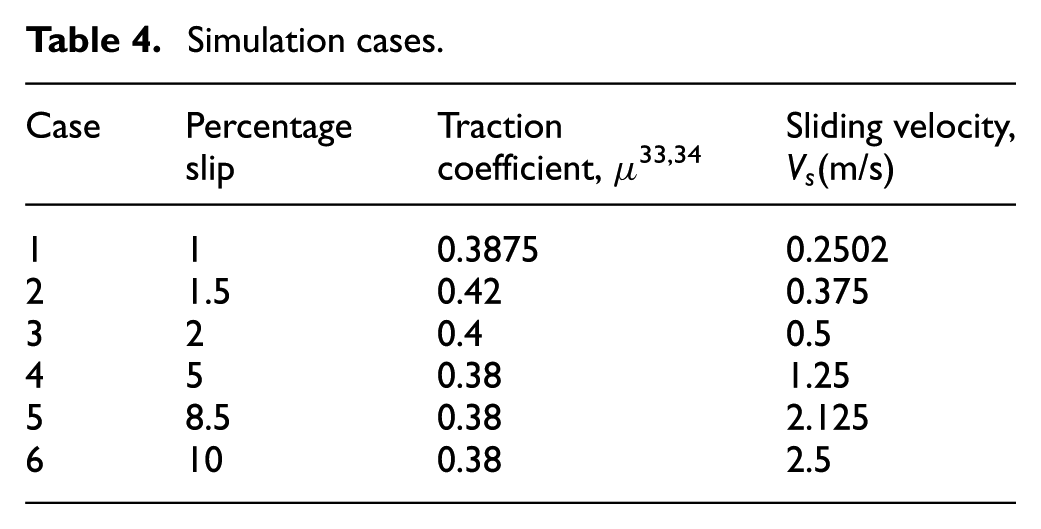
This flux is treated as frictional load over the contact patch. The wheel running condition is simulated by repeatedly translating the heat flux on rail surface from left to right of the domain shown in Figure 11. Traction/friction coefficients for six different slip percentages are taken from the literature. 33 Sliding velocities are calculated for the chosen six slip percentages. The parameters used in six simulation cases are presented in Table 4.
Simulation cases.
7. Model validation
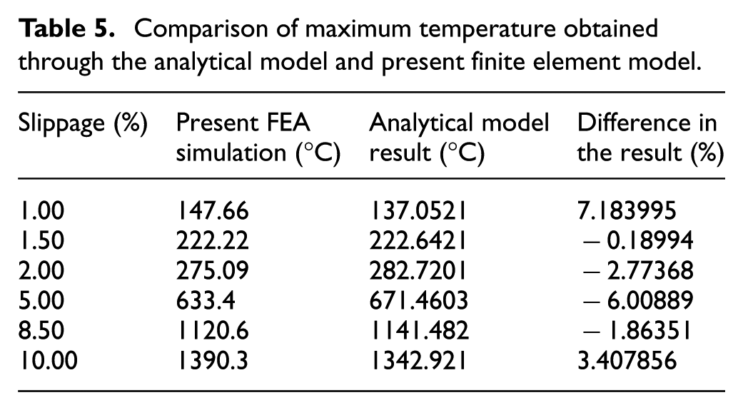
The mesh density in contact region is found to have a direct influence on the accuracy of the solution. 35 In an earlier study by the authors, 26 it was observed that for 1 mm element size in the contact zone, the numerical results could replicate the contact pressure distribution obtained from Hertzian contact theory. In order to re-affirm the analysis of the contact region, mesh with an element size of 1 mm (in the longitudinal direction) is chosen. The maximum temperature obtained from present FEA simulation compares well with the results from analytical model of Ertz and Knothe, 10 thus validates our FEA model. These authors categorically commented that for transient thermal analysis, finite element solutions are more reliable. The results are presented in Table 5.
Comparison of maximum temperature obtained through the analytical model and present finite element model.
8. Results and discussion
In order to estimate the effect of slippage on temperature rise and its effect on residual thermal stress and plastic strain a numerical simulation of the wheel–rail contact conditions are presented. A thermal-elastic-plastic finite element model is proposed for evaluation. Firstly, transient temperature field is obtained for various percentage slip conditions. Then this temperature field is used for the calculation of thermal strains and thermal stresses. Results are presented graphically to view their intensity variations along the contact patch and the rail depth represented in Figure 6(b). The temperature distribution along the depth for six different slip percentages for an instantaneous contact patch is shown in Figure 12(a) to (f). Noticeably, the maximum temperature occurs at higher slip percentage. The location of maximum heat flux is at the center of the contact ellipse, specified by ξ = 0. The leading edge and trailing edge of the ellipse are at ξ = −1 and ξ = 1, respectively. The peak temperatures are found at just prior to the trailing edge (around at ξ = 0.66) of the contact surface. After first wheel pass, the rail temperature does not reduce to the initial rail temperature. Accordingly, the residual heat accumulates by adding heat produced by succeeding wheel passes. This results in incremental temperature rise in the rail material. Residual temperature distribution across the rail depth after eight wheel passes for different slip rates is shown in Figure 13. It is observable that percentage slip variations do not produce any change in temperature distribution in rail section depth beyond 15mm. However, with higher slip rates specifically beyond 5% cognizable stiffer temperature gradient can be noticed up to 15 mm of rail depth.
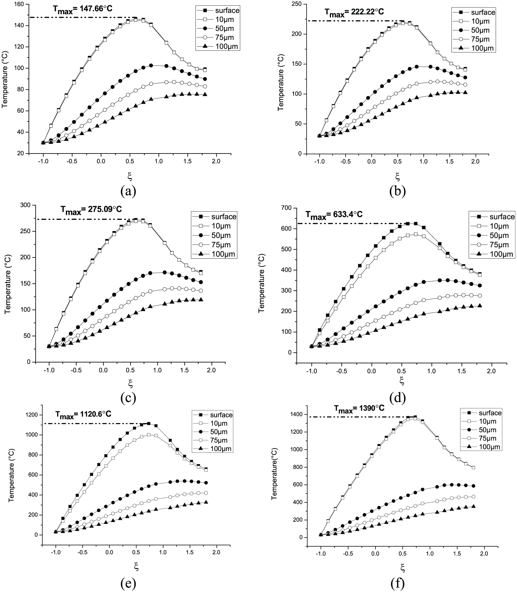
Temperature distribution along the contact patch at different depths for different slip percentages: (a) slip rate = 1%; (b) slip rate = 1.5%; (c) slip rate = 2%; (d) slip rate = 5%; (e) slip rate = 8.5%; (f) slip rate = 10%.
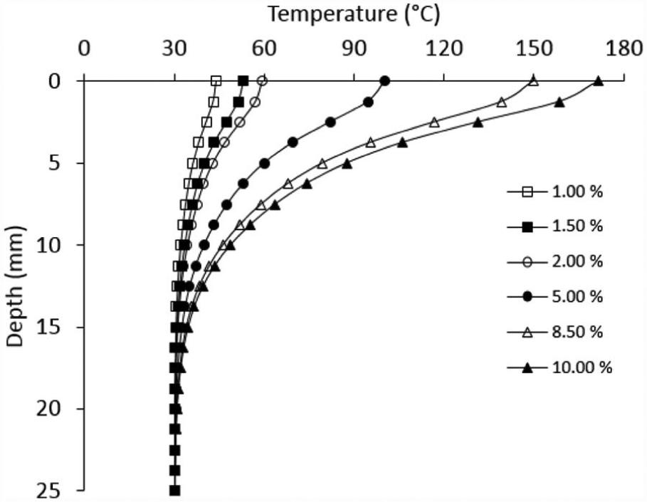
Residual temperature after eight wheel passes along the rail depth for different slip rates.
The layer material temperature once reaches 500°C, as can be seen in Figure 12(d)–(f), and for percentage slip above 5%, the thermal softening phenomenon initiates. This occurs by spheroidization of the cementite phase existing in initial pearlitic structure as lamellar cementite. 1 Spheroidization is also activated by plastic deformation in high-temperature surrounding. Thermal softening favors plastic flow of material and also brings in a reduction in fatigue life of rail material. 1
Figure 14 describes the residual effective plastic strain variation with the depth of the rail material after eight-wheel pass. Since the attained temperatures are more for higher slip rates (5%, 8.5%, and 10%) in regions close to rail surface, the effective plastic strains are also higher for these instances eased by thermal softening of the material. The variations of the effective plastic strain at the rail surface with the increase in wheel passes number for different slip rates are given in Figure 15. This clarifies that the accumulation of plastic strain at the rail surface does not change significantly for a given slip rate and up to eight number of wheel passes considered in this study.
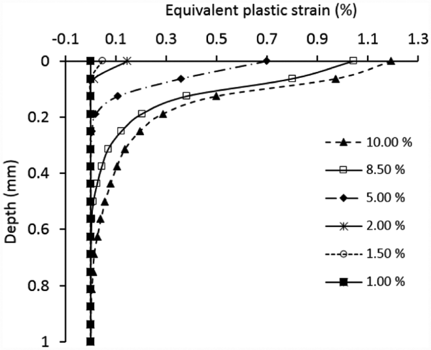
Variation of residual equivalent plastic strains along the rail depth for different slip rates.
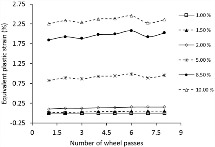
Variation of equivalent plastic strain at rail surface with increasing wheel passes for different slip rates.
Figure 12(e) and (f) correspond to the evolution of maximum temperatures crossing rail material’s lower critical temperature of 723°C for 8.5% and 10% slip rates. At such high temperatures, initial pearlitic rail material transforms to martensite with a BCT crystal structure, 8 which is naturally hard and brittle. During this transformation in the contact patch, about 0.5% volume expansion is observed that induce residual stresses. 9 These residual stresses in combination with rolling contact loading cycle promote crack initiation in hard and brittle martensite. Figures 16 and 17 describe the variation of residual von Mises stresses, along the rail depth, arising from the thermal effects caused by different slip rates after eight wheel passes. These figures indicate that for slip rates up to 2%, the location of maximum von Mises stress occurs at a depth of about 0.1 mm. For higher slip rates (5%, 8.5%, 10%), the location of maximum von Mises stress shifts to a deeper zone of around 0.2 mm. The position and level of von Mises stress signify the onset of plastic flow or condition of material’s ability to resist any crack initiation. Due to higher stress at these locations of rail surfaces, these sites are more prone to crack initiation.
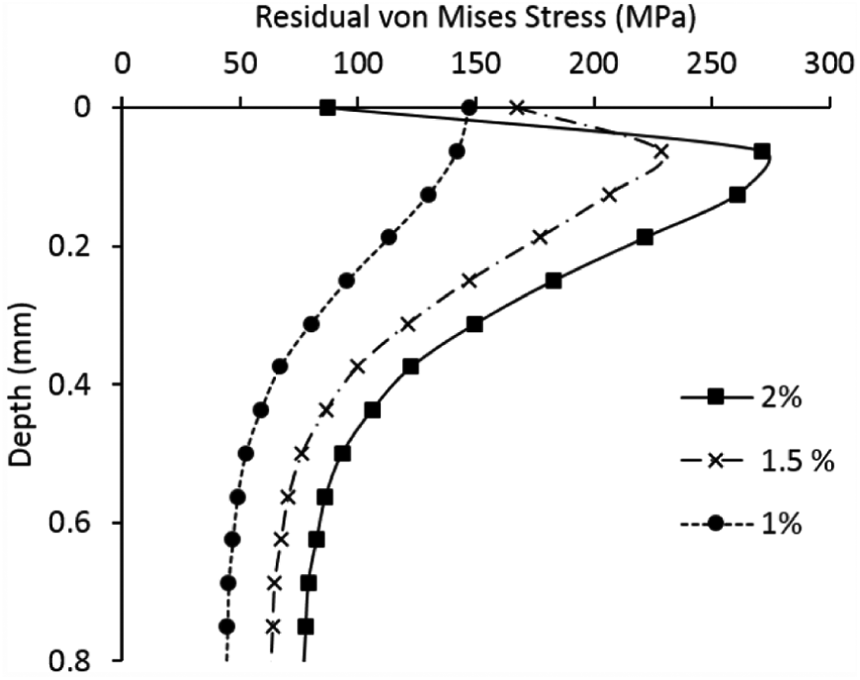
Variation of residual von Mises stresses along the rail depth for lower slip rates (1%, 1.5%, and 2%).
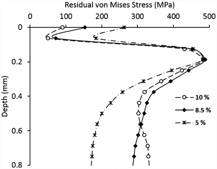
Variation of residual von Mises stresses along the rail depth for higher slip rates (5%, 8.5%, and 10%).
9. Conclusions
Two-dimensional transient thermal and elastic–plastic finite element analysis based solutions are provided to examine the effect of frictional heat generated by change in slip percentage at the dynamic wheel–rail contact interface. Six different slip percentages (1%, 1.5%, 2%, 5%, 8.5%, and 10%) are considered to illustrate their influence in terms of temperature rise, residual thermal stress and plastic strain on the surface and subsurface of the rail material. Surface temperatures of several hundred degrees Celsius are observed. Results indicate that the heat penetration below the surface is shallow and the thermal gradients are steep up to 15 mm. The incremental growth in temperature rise with each rolling pass of the wheel on rail causes thermal softening and hence fosters plastic flow of rail surface material. For higher slip rates, the temperature rises beyond the lower critical temperature. This promotes microstructural transformation of the rail material to martensite formation at outer layer interchangeably stated as WEL. Percentage slip variation is significantly high at curved segments of rail. For reducing wear from wheel–rail flange contact appropriate lubricants are necessary. This study can guide in selection of lubricants to sustain thermal loads. Rail surface damage characterization from friction induced thermal load can be studied in succession. The findings of this research may also help railway operators and maintenance engineers to estimate a priori the thickness of damage on the rail surface and the depth of grinding needed to eliminate it. The study is limited by a specified number of wheel passes considered in the analysis.
Footnotes
Appendix 1
Funding
This research received no specific grant from any funding agency in the public, commercial, or not-for-profit sectors.