
Abstract
To obtain real-time haptic interactions in virtual cockpit systems (VCSs), a real-time trajectory planning method based on kinematical optimization for haptic feedback manipulators (HFMs) is presented in this paper. Firstly, the control panel area is extracted in the workspace of the HFM, in which the interacting point is located. Then a feasible interacting configuration is calculated as the objective configuration of the trajectory encoded by a parametric representation. The trajectory planning problem is formulated as a non-linear optimization problem based on kinematics, which is solved in real-time by finding a good initial solution with machine learning methods. Simulations show that trajectories with a compromise between safety and rapidity can be calculated in real-time by this method, which provides a basis for haptic interaction in VCSs.
Keywords
1. Introduction
The virtual cockpit system (VCS) is a flight simulator with human–computer interaction based on virtual reality technology, in which the physical cockpit and control mechanisms are replaced by virtual display and motion-tracking devices. Compared with the physical cockpit system, the advantages of higher flexibility in the structure and functionality, as well as the lower cost, make the VCS meaningful in flight simulation. 1
Haptic feedback is of great significance for better immersion and interaction in VCSs. However, efforts in this direction are still very limited. 2 In order to achieve haptic interactions in the VCS without sacrificing the advantages of low cost and high flexibility, a haptic feedback system based on the servo serial manipulator is presented. On the basis of the traditional VCS, a mechanical system including a serial manipulator (called a haptic feedback manipulator, HFM) and a concise control panel equipped with different kinds of button linked with the end-effector is placed in front of the user. The position and posture of the user’s hand are measured by motion-tracking sensors as the hand moves. Once the interactive operation is detected, the user is able to see the virtual hand operating the control panel in the virtual environment through the virtual display. Meanwhile, the HFM brings the end-effector with the control panel to the objective position the user intends to operate with to provide haptic feedback.
To achieve interactions with human hands, trajectory planning for the HFM according to hand motion is required, which brings the corresponding button on the end-effector to the predicted interacting point at the interacting time. Two key problems need to be solved.
Interacting configuration determination, that is, determination of the objective configuration of trajectory planning. The objective of trajectory planning is to make the manipulator move from the current configuration to the interacting configuration corresponding to the interacting point, which is located in the simulated control panel area. Therefore, we need to analyze the workspace of the HFM, extract the control panel area, and consequently determine the interacting point and its corresponding configuration.
Real-time trajectory planning. There are three key points. (a) Real-time performance. The trajectory needs to be re-calculated according to the variation of the predicted interacting configuration. One trajectory planning needs to be done in one predicting period. (b) Rapidity of motion. The motion time of the HFM is required to be as short as possible to make sure that the end-effector can reach the objective point before the human hand to provide haptic feedback. (c) Safety of motion. The positions, velocities, accelerations, and torques of the joints of the HFM need to be restricted to avoid injuries to users.
To satisfy the above requirements, firstly, we analyze the workspace of the HFM and extract the optimal control panel area, which is used to determine the interacting point and the corresponding interacting configuration. Then, a non-linear optimization model is established on the rapidity and safety criteria, in which the trajectory is encoded by a parametric representation. Finally, the global minimum is solved by finding a good initial solution through the regression model, which is obtained by machine learning methods with the database generated offline.
1.1. Related work
1.1.1. Haptic feedback in the VCS
To achieve haptic feedback in the VCS, Semi-Virtual Reality Cockpit solutions have been proposed3,4 based on the principle that “Seeing is virtual and touching is believing.” The scenes in and out of the cockpit are created by the virtual reality technology, while all touchable parts keep 1:1 proportions to provide haptic feedback. However, due to the large size and poor flexibility, these solutions sacrifice the advantages of the VCS.
Another VCS scheme was developed by STRICOM with haptic feedback achieved by the TOPIT (Touched Objects Positioned in Time) technology.5,6 A mechanical system equipped with various kinds of buttons is placed in front of the user. Each button is used to simulate all the buttons of the same type in the real cockpit. When the user’s hand moves, the servo system brings the desired button to the position the user aims at to provide haptic feedback. The control panel is simplified and different kinds of control panels can be simulated only by changing software. However, the mechanical system is still large. Moreover, the button can only move in a two-dimensional plane area so that interactions in three-dimensional space are barely achieved.
We improve the TOPIT scheme by employing a serial manipulator as the servo mechanical system, which can achieve three-dimensional movement with smaller size, larger workspace, and better flexibility.
1.1.2. Trajectory planning for the serial manipulator
The traditional point-to-point trajectory planning is started from interpolation-based methods, such as polynomial interpolation7,8 and B-spline interpolation.9,10 In general, pure interpolation-based methods are able to accomplish the required tasks, but fail to achieve optimal performance in specific aspects. To overcome this shortcoming, some trajectory planning methods are presented based on non-linear optimization.11,12 The non-linear optimization problem is developed with an optimal objective based on time, energy, and power consumption. Constraints such as mechanical structure, time, and obstacle avoidance 13 are considered as well. Von Stryk and Schlemmer 14 investigated non-linear optimization with three separated criterions of minimum time, minimum energy, and minimum power consumption and solved it by a numerical method of combining a direct collocation and an indirect multiple shooting method. Chettibi et al. 15 presented the optimal planning problem and tried to find a trade-off between time, energy, and power consumption and solved it using the Sequential Quadratic Programming (SQP) method. However, none of the aforementioned optimization-based methods are real-time due to the complex computation of non-linear optimization.
Bäuml et al. 16 presented three pure kinematical objective functions and implemented parallel computation with multiple initial solutions to obtain the global minimum in real-time. However, their method has a stringent demand for hardware due to the parallel computation with 32 CPU cores. Lampariello et al. 17 and Werner et al. 18 take the dynamics into consideration and consider the criterion of minimum power consumption. Several machine learning methods are adopted to find the global minimum in real-time. However, this method is only suitable for the case of a fixed initial robot configuration and a fixed starting point of the target trajectory.
Recently, a different approach to generate trajectories originated from trajectory learning and generalization, learning-by-demonstration (LbD),19,20 has been presented. The motion of a manipulator is modeled as a dynamical system21,22 whose parameters are learned from demonstration by a human. With this method, natural human-like movement can be achieved by robots. Furthermore, it is suitable for a dynamic environment with obstacles and disturbances, since it is able to model the non-linear and uncertain factors in a mechanical system. However, compared with the optimization-based method, it is unable to obtain the optimal solution according to some criteria.
To achieve the safety and real-time performance of the haptic feedback system, we combine the trajectory planning method based on non-linear optimization with the real-time solving method based on machine learning. The non-linear optimization problem is established with the criterion of safety and real-time performance to find the trade-off between them. Machine learning methods are implemented for choosing the initial guess of the solver to overcome the high computational complexity of non-linear optimization.
2. Haptic feedback system based on the servo serial manipulator
2.1. Haptic feedback system
A haptic feedback system for the VCS based on the servo serial manipulator is introduced in this paper. As shown in Figure 1, it consists of motion-tracking sensors, computers, and a serial manipulator, called the HFM, linked with a concise control panel. Motion-tracking sensors are used to track hand motion and detect interactions. The concise control panel linked with the end-effector of the HFM is equipped with various kinds of buttons, such as a pressing button, rotating button, and sliding button, which provide haptic feedback to users. Computers work to perform hand trajectory prediction, trajectory planning, and control for the HFM.
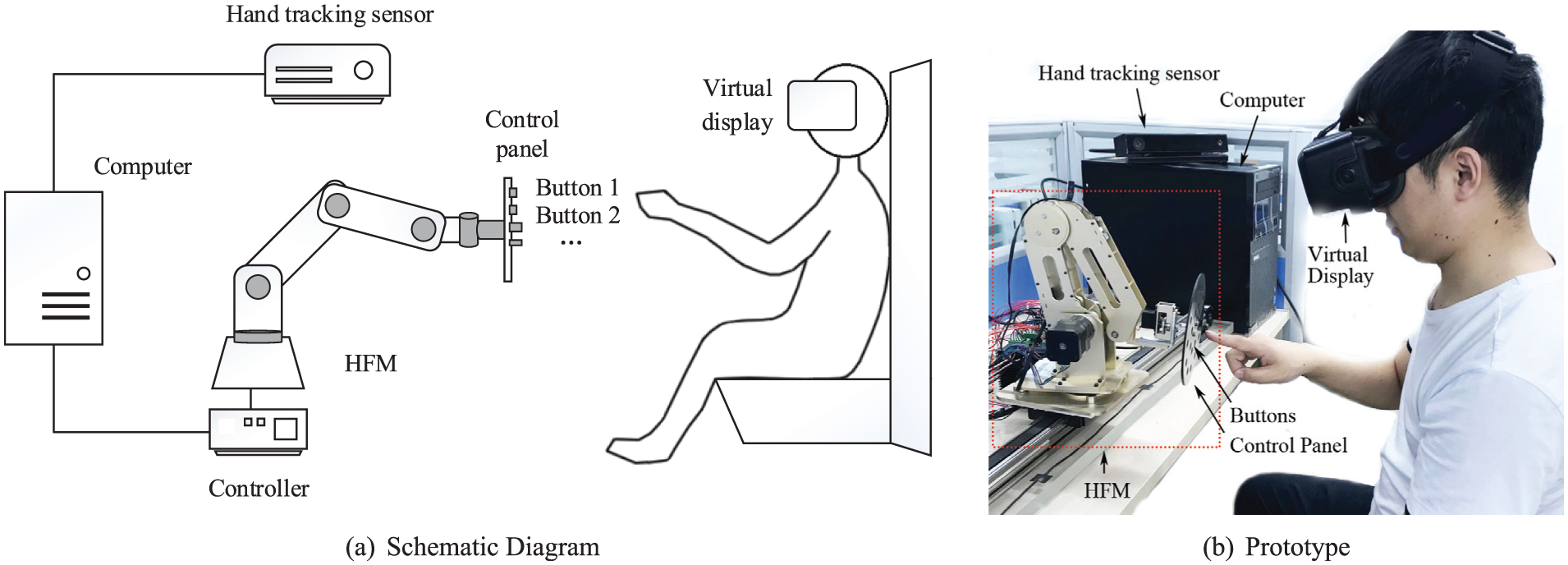
Components of the haptic feedback system based on the servo serial manipulator. HFM: haptic feedback manipulator.
The workflow is shown in Figure 2. When the user’s hand moves, hand motion data are measured by tracking sensors, and then processed by computers to calculate the position and pose, predict the trajectory of the user’s hand, and determine the interacting time
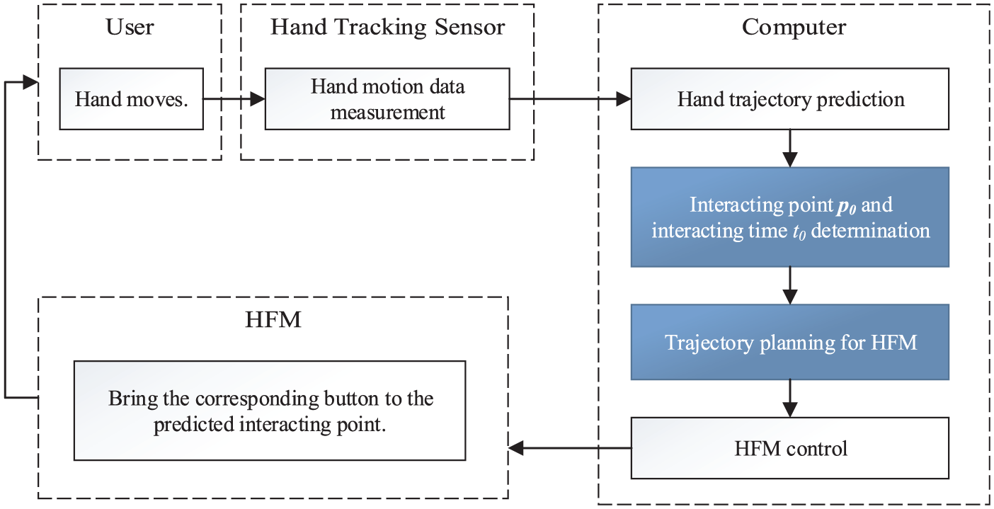
Workflow of the haptic feedback system. HFM: haptic feedback manipulator.
This haptic feedback scheme needs merely a concise control panel with several buttons instead of the full-scale control panel in a real cockpit, for which the size and cost are greatly reduced. Compared with TOPIT, the spatial movement in three dimensions can be achieved with a smaller size and larger workspace by employing a serial manipulator. In addition, different types of aircraft can be simulated only by changing the specific software, making it more flexible in functionality.
2.2. Haptic feedback manipulator
A six-degree-of-freedom (6-DOF) serial manipulator is adopted as the HFM in this paper (Figure 3). The six joints of the serial manipulator are the waist, shoulder, elbow, pitching wrist, yawing wrist, and rotating wrist joint. The position of the end-effector is determined by the waist, shoulder, and elbow joints, while the orientation is determined by the three wrist joints. The pitching wrist and yawing wrist joints are used to adjust the orientation of the concise control panel. In addition, the rotating wrist joint is used to switch the states of some buttons to further reduce the number of buttons on the control panel. For example, the state of a sliding button can be translated from on to off, or in reverse, by rotating 180 degrees.
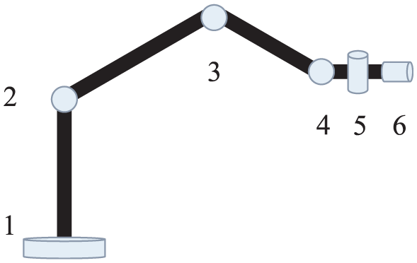
The structure of the haptic feedback manipulator. 1: waist; 2; shoulder; 3: elbow; 4: pitching wrist joint; 5: yawing wrist joint; 6: rotating wrist joint.
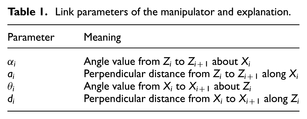
The Denavit–Hartenberg (DH) convention
23
is adopted to describe the kinematic chain of a manipulator, as shown in Figure 4.
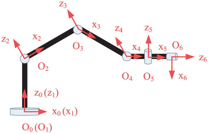
Denavit–Hartenberg coordinate system of the haptic feedback manipulator.
Link parameters of the manipulator and explanation.
3. Workspace analyses and interacting configuration calculation
3.1. Workspace generation and control panel area extraction
According to the workflow of the haptic feedback system shown in Section 2.1, we first need to predict an interacting point, which serves as the objective of trajectory planning for the HFM. To achieve the consistency of the virtual environment and real word, we need to extract an area in the reachable workspace of the HFM to simulate the control panel, in which the interacting points are located. In addition, as users and the HFM work in a shared workspace and perform physical interaction, the motion range of the HFM is influenced by hand motion to guarantee the reality and safety of human–robot interaction. Therefore, it is necessary to perform workspace analysis of the HFM.
In real cockpits, multiple control panels are distributed almost in all the directions around the pilot. This paper aims at theoretical research on trajectory planning of the haptic feedback servo system and does not consider any specific airplane model type. Top panels and lateral panels are thus neglected. We take the control panel located right forward, for example, and simplify the control panel as a flat rectangular panel on which button distribution is designed artificially.
Firstly, the reachable workspace of the HFM is generated by the Monte Carlo method, which is denoted as
Then, the reachable workspace is divided into parts A and B by plane C (called the control panel plane), as shown in Figure 5. The control panel area, in which all the contacts of the user’s hand and the end-effector of the HFM performed (denoted as
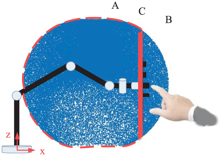
Interaction of the end-effector and the user’s hand. (Color online only.)

Control panel plane and control panel area.
As shown in Figure 8, the reachable workspace is symmetrical with respect to the plane xOz. The z-axis is perpendicular to the ground. The user’s hand gets close to the manipulator along the opposite direction of the x-axis. Therefore, we select a plane perpendicular to the x-axis as the control panel plane, which is symmetrical with respect to the plane xOz and is located right forward of the user. The workspace is divided into a series of layers perpendicular to the x-axis, in which a layer is selected as the control panel plane. As the layered result shows (Figure 9), the point distribution in the workspace is non-uniform and a cavity exists inside the workspace. The density of the points close to the center of the workspace tends to be larger, which indicates that the manipulator is more flexible. Likewise, the area of the cross-section becomes larger. However, there is a cavity inside the workspace, which is unreachable for the end-effector and thus the control panel area should be kept away from it. Consequently, to obtain a control panel plane with larger area and better joint flexibility, while keeping it away from the cavity, the first layer back to the cavity is selected as the control panel plane. Finally, a rectangular area with the largest area in this plane is extracted as the control panel area.
3.2. Interacting configuration determination
When the user’s hand moves, the trajectory of hand motion is predicted by the haptic feedback system. The interacting point
According to Section 2.2, the position of the end-effector is only determined by the first three joints. Thus,
To guarantee the control panel is perpendicular to the x-axis, we have the following:


and according to the required direction of the particular button,

In addition, if more than one feasible solution of
4. Real-time trajectory planning based on kinematic optimization
4.1. Problem statement
When the haptic feedback system works, the trajectories of the hand movement and the interacting point are predicted according to the current hand motion periodically with the period
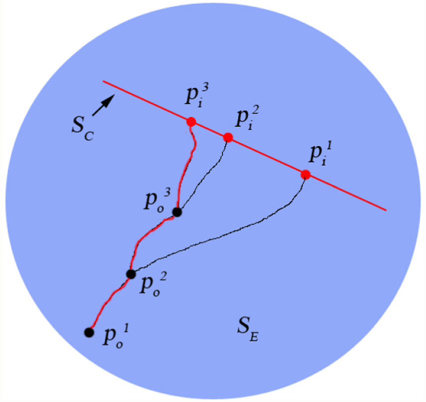
End-effector trajectory of the haptic feedback manipulator.
As for the trajectory planning in each period, it is necessary to generate a trajectory from the initial configuration
The trajectory planning problem is generally costly due to its strong non-linearity and the requirement of frequent re-planning. To achieve the real-time performance, some assumptions and approximations are made to simplify the problem.
The trajectory planning is implemented in joint space. Three joints of the HFM are required to reach the objective configuration at the same time, which are planned independently. Compared with Cartesian space, joint space planning has low computational complexity without large amount of inverse kinematics calculations, since the controller actuates joint motion in joint space. In addition, it is convenient to implement mechanical constraints, for example, constraints of position, velocity, and acceleration of joints. Furthermore, mechanism singularity can be avoided.
A pure kinematical optimization is chosen, in which the objective function and constraints depend only on positions, velocities, and accelerations of joints, not on the torques. Dynamics is significant in the motion of the manipulator, but complicated in computation and costly in time, which are unsuitable for real-time applications. As for haptic feedback application, the joint velocity constraints dominate the manipulator motion, since the motion time is short and the acceleration and deceleration phases take up a slight proportion. Therefore, the details of acceleration and deceleration are less important for overall performance and we just need to conservatively choose the maximally allowed acceleration to ensure that the torque never exceed its limit.
The movements of the HFM are encoded by trapezoidal velocity ramps. As argued above, the precise characteristics of the acceleration and deceleration phases are not essential for the overall performance. Trapezoidal ramps can be easily analytically expressed with a few independent parameters, and significantly simplify the computation since only acceleration and maximum velocity need to be limited.
4.2. Trajectory parameterization
Trapezoidal velocity ramps are employed to encode the trajectories, which consist of three phases as follows: uniform acceleration phases
We define the following:

where
The trajectory of each joint can be represented as follows:
For each joint, the trapezoidal ramp can be defined by two independent parameters: a and
The parametrized trajectory is represented as follows:
4.3. Kinematical non-linear optimization
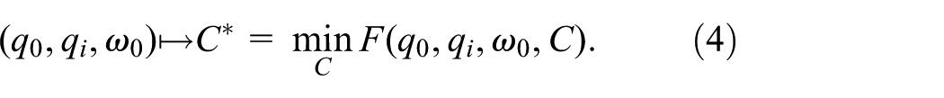
4.3.1. Optimization problem
The non-linear optimization problem with non-linear constraints can be described as follows:
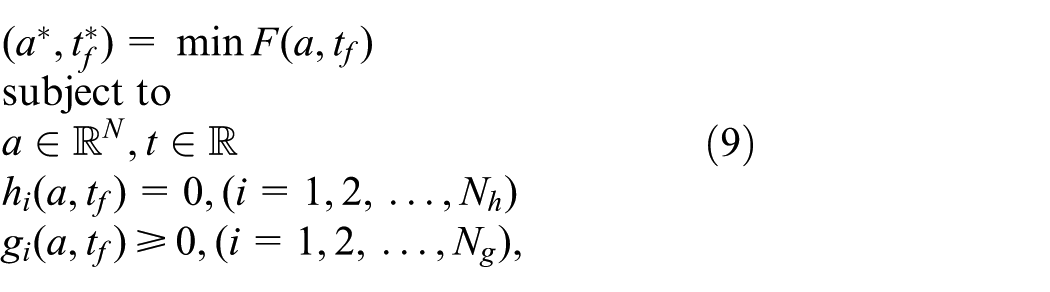
where F is the objective function and
4.3.2. Objective function
Three optimization modes are presented in this section.
Safety is one of the most important factors in human–manipulator interaction applications. To ensure safety, the HFM is required to move softly with accelerations that are as small as possible:
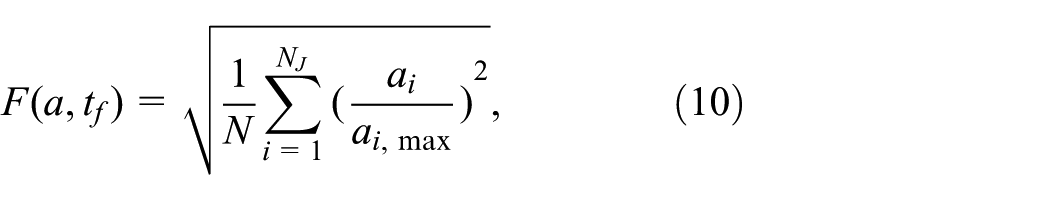
where
To achieve rapidity of motion, the HFM is required to reach the objective configuration quickly with motion time as small as possible:

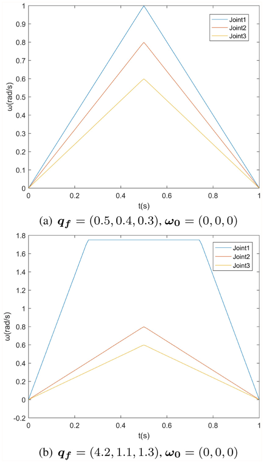
Simulation results show that the acceleration minimization mode is usually mechanically harmful if working in the acceleration phase all the time (Figure 11(a)) or working with maximum velocity (Figure 11(b)). In addition, working with small acceleration requires large motion time, which may reduce the rapidity performance. Similarly, the motion time minimization mode is less safe due to working with large acceleration (Figure 12).
To compromise the safety and rapidity of the motion, we consider a balance between acceleration and motion time as follows:
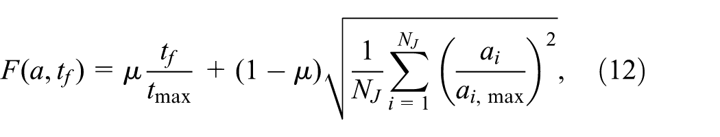
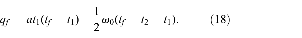
which can be converted to the following:
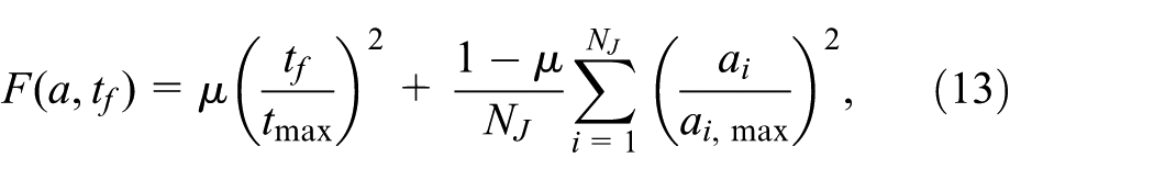
where
4.3.3. Constraints
The joint offset from the current configuration to the objective configuration, that is, the interacting configuration, is as follows:

The trapezoidal velocity ramps are satisfied to the following:


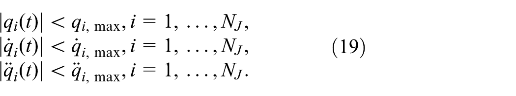
The positions, velocities, and accelerations of the joints are required not to exceed the mechanical limitations during the motion:
The HFM is required to reach the interacting configuration before the time user’s hand reaches the interacting point:

4.4. Real-time solver based on machine learning
The SQP method is adopted to solve the non-linear optimization problem to minimize the objective function described in Section 4.3.2 satisfying the constraints in Section 4.3.3. The solver easily becomes stuck in the local minimum due to the non-linearity of manipulator’s kinematics. It would be difficult to obtain the global minimum by randomly choosing an initial solution. To overcome this problem, different initial guesses are chosen to generate a set of local minima, in which the best is taken as the global minimum. This method is rarely used in real-time applications since it takes a prohibitively long time to solve a large number of non-linear optimization problems. For example, it takes about 1 minute and 8 seconds to handle 625 and 81 groups, respectively, of initial guesses for three-degree-of-freedom (3-DOF) robots.
Therefore, a machine learning-based method is presented to choose a good initial guess of
The detailed procedure is as follows, in which Steps (1) and (2) are offline and Steps (3) and (4) are online.
(1) Generate database.

(2) Establish the mapping from joint variations to parameters.
The motion time is the primary parameter we are concerned about, since the joints are required to reach the objective positions at the same time. Therefore, motion time

Then other parameters are determined according to

(3) Choose a good initial guess.
For an arbitrary

(4) Calculate the global optimization.
The optimal parameters
5. Results
5.1. Workspace analyses
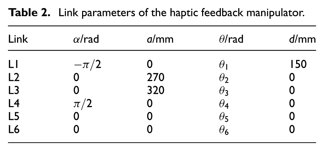
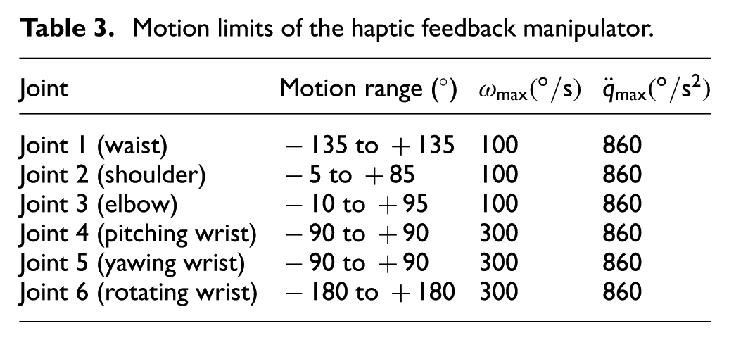
The link parameters and motion limits of the HFM are chosen, as shown in Tables 2 and 3, respectively.
Link parameters of the haptic feedback manipulator.
Motion limits of the haptic feedback manipulator.
The workspace is simulated by the Monte Carlo method with 100,000 points. Examples of the obtained point clouds are shown in Figure 8.
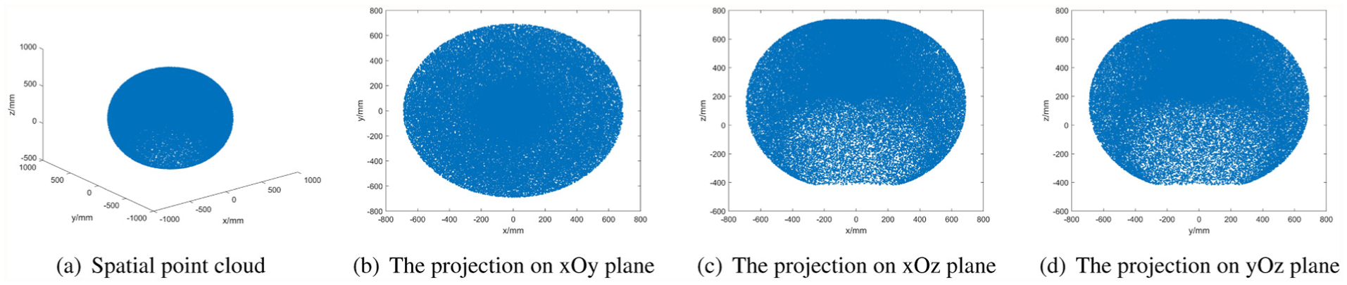
The reachable workspace of the haptic feedback manipulator.
The point cloud is divided into 40 layers along the x-axis and the projection on plane yOz of each layer is shown in Figure 9. It can be seen that a cavity exists in Layer 34 and vanishes in Layer 35. Therefore, Layer 35 is selected as the control panel plane and the largest rectangle in it is extracted as the control panel area, which is delineated by the red lines in Figure 10.
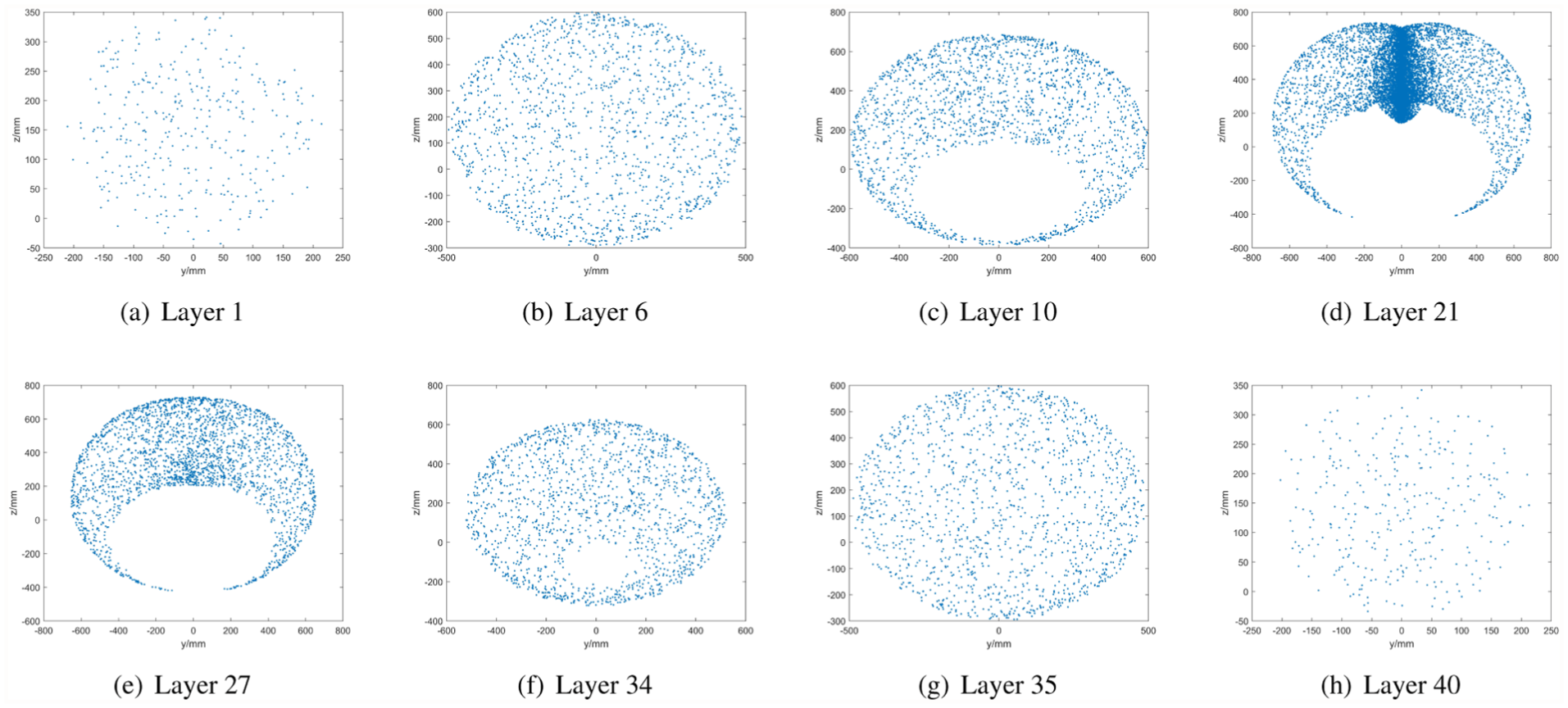
Projection of each layer of the workspace.
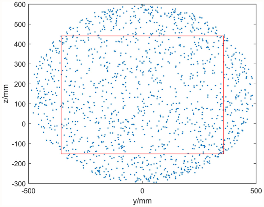
Control panel area. (Color online only.)
5.2. Real-time trajectory planning
5.2.1. Three optimization modes
To analyze the performance of non-linear optimization, we first consider
Firstly, the velocity profiles of the three optimization modes are depicted.
The case
We choose
Velocity profile of the acceleration minimization mode.
We choose
Note that in this mode, the acceleration is as small as possible and therefore the motion time is quite large so that it reaches the upper limit. In the case of Figure 11(b), for a large expected variation of Joint 1, it works with the maximum velocity for a long time to reduce the acceleration.
The case
We choose
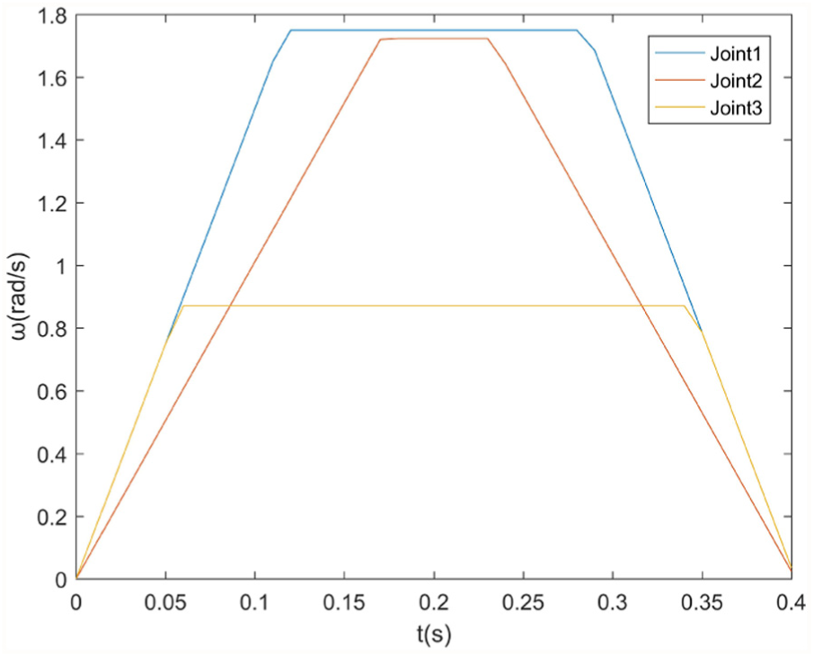
Velocity profile of the motion time minimization mode.
We choose
Results with different
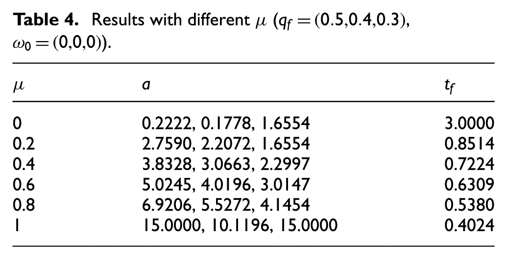
Results with different
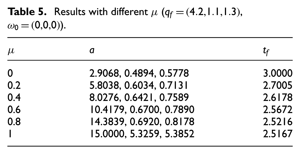
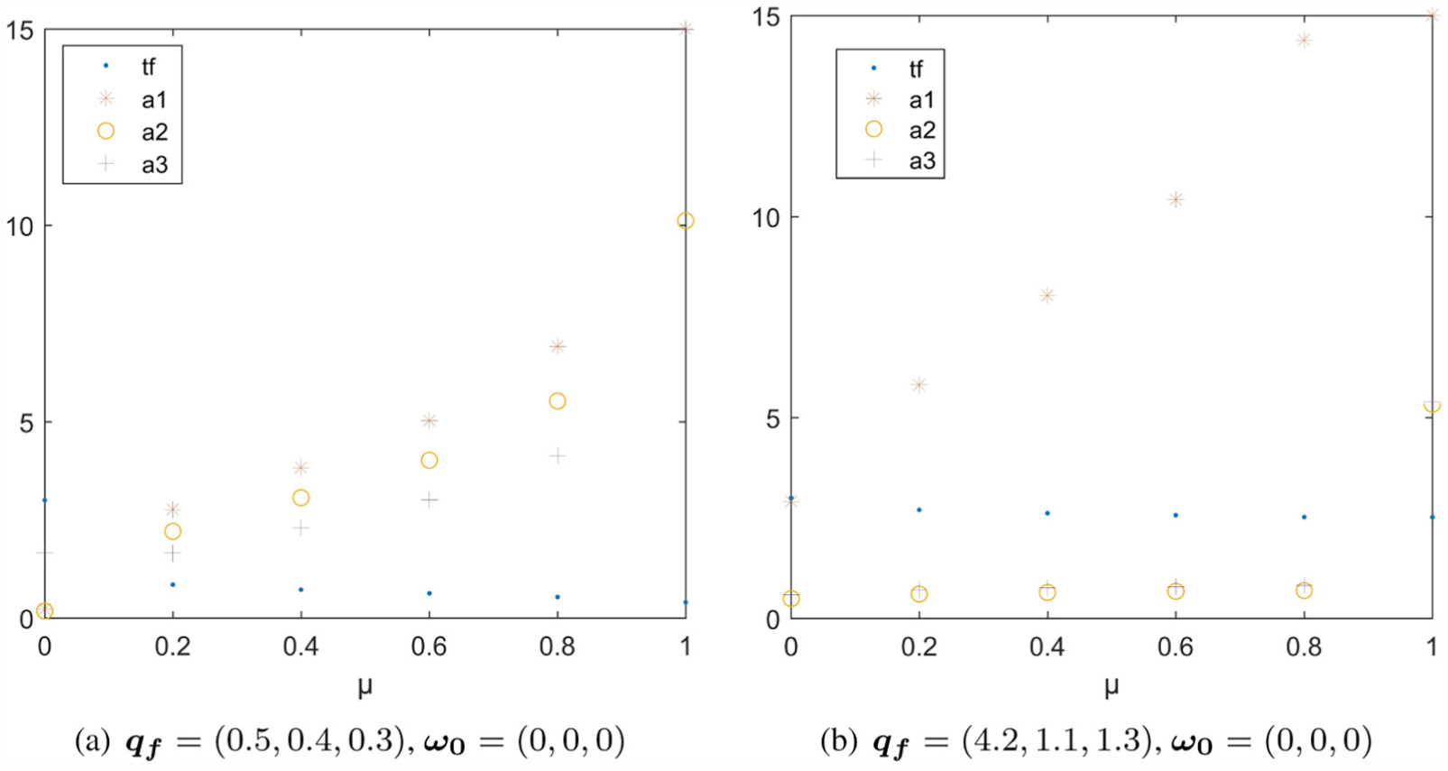
Results with different
Comparing Tables 4 and 5, we can see that the joint variations of Joints 2 and 3 in Group 2 are larger than those of Group 1, but the accelerations are smaller. This is due to the increase of motion time caused by the significant large variation of Joint 1 in Group 2. It shows that the parameters are dominated by the joints with large variation.
5.2.2. Local minimum and initial guess
In the case
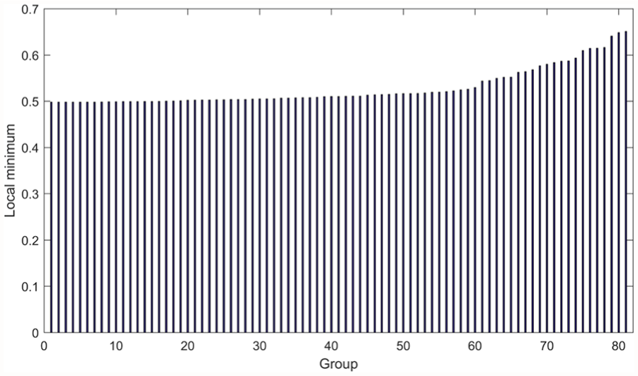
The distribution of local minima corresponding to different initial guesses.
The minimum of these local solutions is 0.4979 (Group 1) and the maximum is 0.6509 (Group 81), which is 30.72% larger than Group 1. Therefore, it is necessary to choose multiple groups rather than only one group of initial guesses to find the global minimum.
The first 20 groups of local minima increase slowly, in which the value of Group 20 is only 0.81% larger than that of Group 1. Therefore, the solution of Group 1 can be taken as the global minimum.
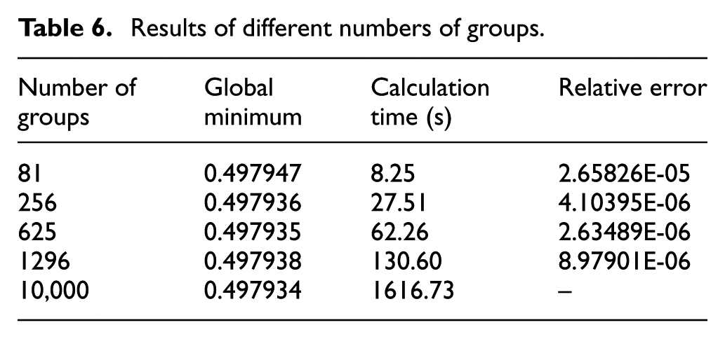
The more groups of initial guesses are adopted, the more accurate the obtained global minimum is, but the longer the calculation time will be. The relative errors and calculation times of different numbers of initial guesses are shown in Table 6. It can be seen that from 81 to 10,000 groups of initial guesses chosen, the relative errors are all very slight but the calculation time increases rapidly. Thus, we choose 81 groups of initial guess to reduce the computation cost as well as satisfy the precision.
Results of different numbers of groups.
5.2.3. Machine learning-based solver
Firstly, we randomly select 1200 groups of joint states in the motion range (shown in Table 3). For each group of joint states, 81 groups of initial guesses are used to calculate the global minimum. Then a database is generated with
By randomly choosing
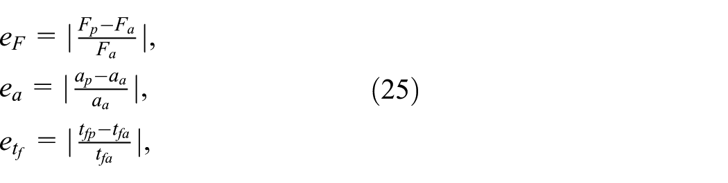
where
The relative errors of the objective function value and the parameters are shown in Table 7, and the calculation time is shown in Table 8. The following can be concluded.
The relative errors of the objective function values obtained by SVR and GPR are 0.47% and 0.27%, respectively, which are both very slight. The GPR model is more accurate than the SVR model, but takes much longer time to build offline.
The relative errors of
The relative error of
The online calculations for optimal parameters cost 25.63 ms on average, which can be implemented in real-time.
Relative errors of objective function value and parameters.
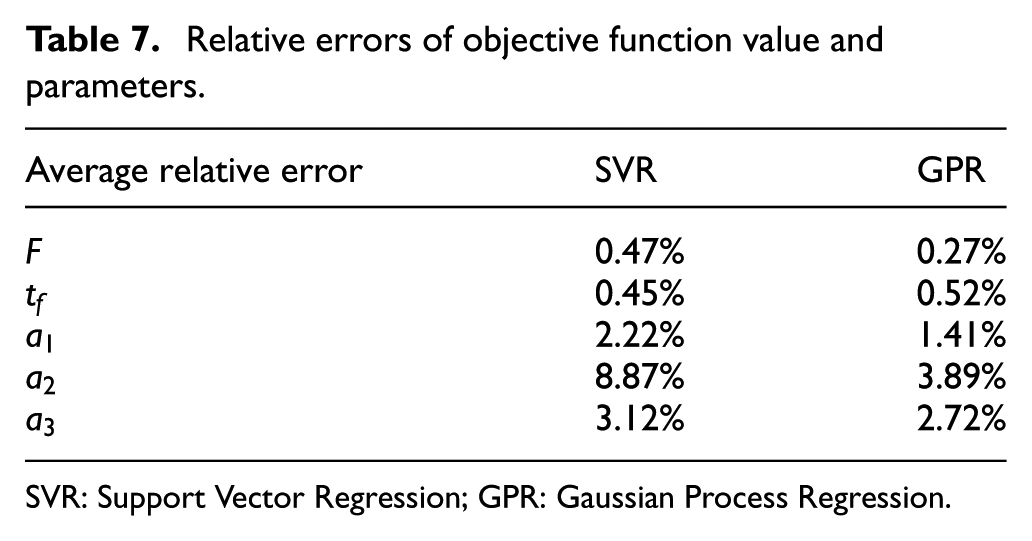
SVR: Support Vector Regression; GPR: Gaussian Process Regression.
Calculation time.
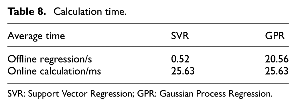
SVR: Support Vector Regression; GPR: Gaussian Process Regression.
5.3. Trajectory planning for haptic feedback
In haptic feedback applications, the trajectory is re-planned in every prediction period according to the updated interacting point and time. Considering the 6-DOF HFM described in Section 2.2, we select
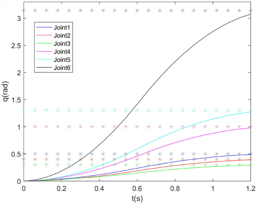
Predicted positions at each period and position profiles of the entire course.
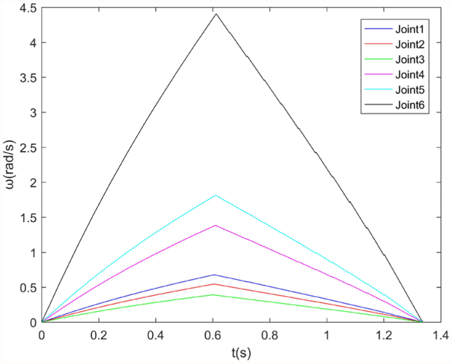
Velocity profiles of the haptic feedback course.
The whole process includes 21 trajectory planning periods, which are illustrated by examples in Figure 17. Trajectory planning of each period on average costs 38.78 ms. The calculation time of each period is below
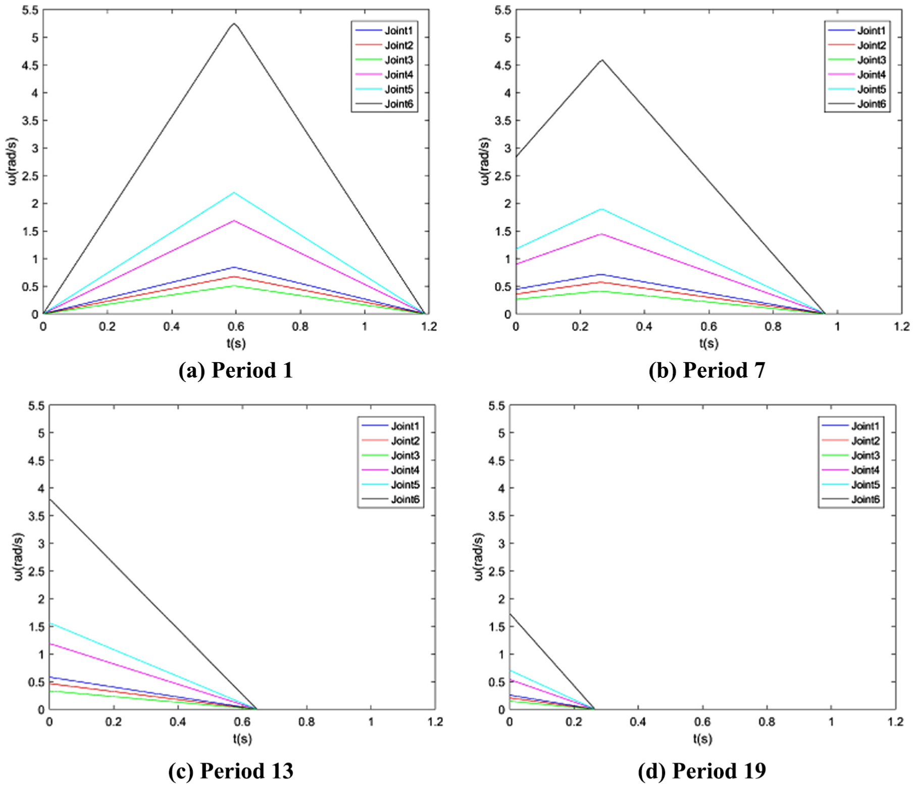
Velocity curve of each period.
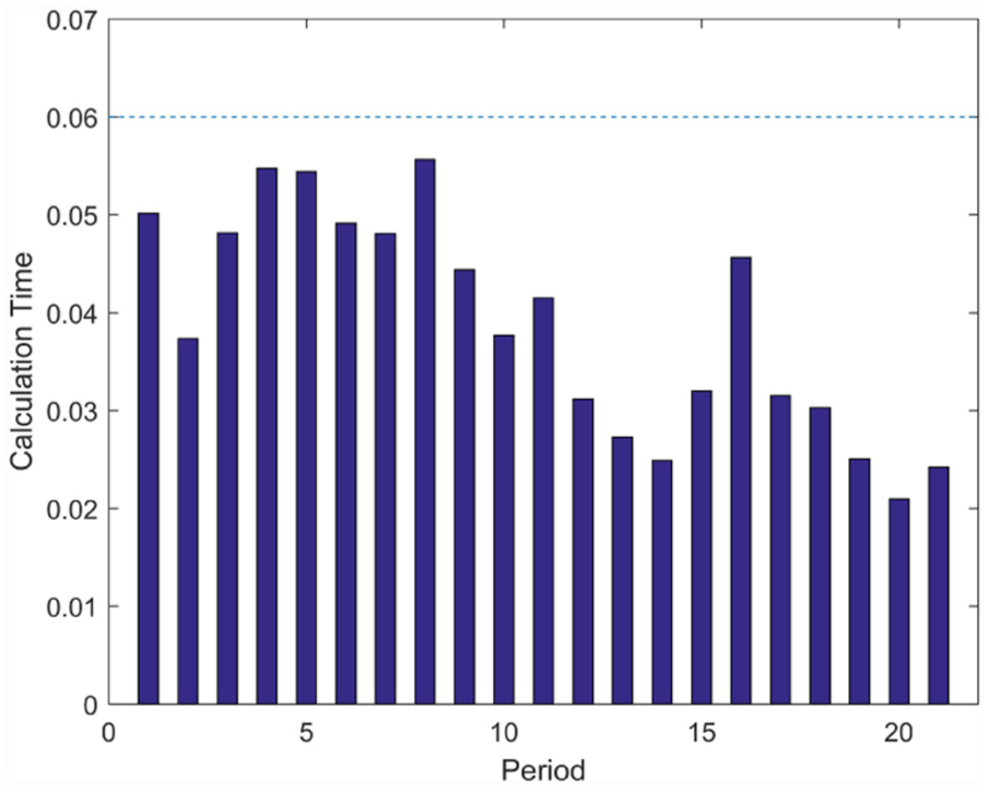
Calculation time of each period.
6. Conclusion
A haptic feedback scheme for the VCS based on the servo serial manipulator and a trajectory planning method for it are presented in this paper. We analyze the workspace of the HFM and firstly find the interacting configuration as the objective of trajectory planning. Then trajectory planning based on kinematical optimization is performed and solved in real-time with the machine learning method.
A haptic feedback system based on the servo serial manipulator is presented and the type of the manipulator is determined.
An interacting configuration determination method is presented. Firstly, the control panel area is extracted by analyzing the workspace of the HFM. Then the interacting point and the corresponding interacting configuration are determined by intercepting the hand trajectory with the control panel.
A trajectory planning method based on kinematical optimization and a real-time solver based on machine learning are presented. The trajectory planning problem is formulated as a non-linear optimization problem based on kinematics and the global minimum is found in real-time by choosing a good initial solution with the regression model built offline.
However, some limitations should be considered in future work.
In this paper, we simplify the control panel of real cockpits, only considering the forward panel. In future work, we would like to develop the HFM by adding DOFs to simulate multiple control panels in different directions and make it close to the real situation.
The trajectory planning method presented in this paper is based on kinematics and the trapezoidal velocity profile, which is incapable of torque limitation. In future work, we would like to extend this method to dynamics by considering torque and energy in non-linear optimization and using polynomial interpolation for trajectory parameterization.
Footnotes
Funding
This research received no specific grant from any funding agency in the public, commercial, or not-for-profit sectors.