
Abstract
This paper presents the concept of a novel telemanipulator for minimally invasive surgery, along with numerical analysis to validate the main system performance. The proposed kinematic structure consists of a passive and an active module. The passive module is similar to the Selective Compliance Assembly Robot Arm - SCARA robot. The active module is based on a parallelogram mechanism. The results of the numerical study are discussed, focusing on the influence of geometry parameters of the kinematic chain on the displacement accuracy of the end-effector. In particular, the paper deals with the identification of the main factors that impact the position accuracy of the robot.
1. Introduction
Over the past years, robotics has played an important role in the medical practice of clinical hospitals and small institutions, providing medical health services and improving the life quality of patients.
Due to the use of robotics, medical centers and institutions may provide a broad range of treatments and therapies, achieving a strong position in the market. In addition, medical robots may positively affect the activities of the surgeon and the medical staff, thus increasing the success of therapies. From the patient’s perspective (e.g., customer service supported by new technology), innovative robot-assisted medical procedures, usually associated with less stress before and after surgical intervention, help in health recovery and provide a quicker return to daily activities.1–5
Analyzing the state of the art and robotic applications,6–9 as well as observing the offers available on the market, robots may be classified by the type of purpose that they are mainly used for:
rehabilitation (wheelchairs and systems to maintain a stable position of the patient)10,11;
hospital service (personal patient care robots and robotic transport systems)12,13;
surgical procedures (telemanipulators and robots for locating and assisting with diagnostics).14,15
Currently, surgical robots are the most effective and advanced medical devices. 8 They combine the latest innovations in the field of materials science, engineering, mechanics, electronics, control, and information processing. Most of them are used for minimally invasive laparoscopic procedures (MIS – minimally invasive surgery).16–21 Over the past years, MIS has played a crucial role in improving medical practices. It is based on small incisions of the body (e.g., abdominal wall), allowing the access for surgical instruments and cameras. This method offers significant advantages in terms of high accuracy and low risk of infection, including reduced trauma to the body. In addition, MIS allows for reducing any negative effects of hand tremors or unsteadiness during surgeries. The main feature of such treatments is the use of special tools (graspers, retractors, coagulants, endoscopic cameras, etc.) that are inserted into the abdominal wall through the trocar cannulas (usually three or four), located in small skin incisions of the patient. 22 These procedures, called "keyhole surgery," are carried out without the direct visual perception of the surgeon. The small incision avoids blood loss and lowers the chance of post-operative complications, guaranteeing faster convalescence and reduced costs of patient care. These types of procedures also have an important post-operative cosmetic effect on the patient, compared with traditional approaches.
Currently, there is a broad range of available telerobotic systems.23–27 Nevertheless, there are many open challenges and opportunities to improve system performances by focusing on robot kinematic chain and geometry parameters.
This paper aims at describing the conception model of a novel surgical telemanipulator dedicated to MIS. It also presents the results of a numerical study of stiffness on the proposed surgical telemanipulator. In particular, the influence of geometric parameters of the kinematic chain on the displacement accuracy of the end-effector (quality of positioning, robotic laparoscopic instrument) is evaluated and discussed. The positioning accuracy of the surgical telemanipulator provides a fundamental contribution to the effectiveness of the mechatronic model. The paper is concluded with a discussion of the results and directions for further research. All of this constitutes the basis for the next steps in developing the mechatronic system prototype.
This paper presents a telemanipulator based on the primary concept of the use of the medical robot arm in MIS developed by Trochimczuk. 28 This is the result of a set of evaluations and optimizations performed in previous studies and solutions of surgical robots.8,29 For geometrical modeling and numerical analyses, SolidWorks (computer-aided design (CAD)) and SolidWorks Simulation (computer-aided engineering (CAE)) have been used, respectively.
2. Materials and methods
2.1. Conception of a novel telemanipulator for minimally invasive surgery
Currently, many research centers design and develop new constructions of surgical robots.8,30 This is due to the increased demand for mechatronic devices in performing specific medical procedures. Therefore, designing a compact telemanipulator with highly accurate positioning of the surgical tool is becoming a priority.
In order to design a mechatronic surgical robot system properly, it is required to apply formal methods of conceptual design using models of hierarchical31,32 and mechatronic action systems. 27 After that, the construction of a telemanipulator, which consists of 11 links (Figures 1 and 2), is performed during the detailed design phase. Two main groups of links of the kinematic chain are defined as the passive manipulator and the active manipulator. The passive manipulator is represented by links 1–4 attached to a fixed column 0 (Figure 2). This structure is similar to a modified construction of the Selective Compliance Assembly Robot Arm (SCARA) robot. The use the revolute joints in the proposed surgical telemanipulator allows for a more precise, consistent, and faster movement of the passive and active manipulator to the desired position during a surgical procedure on the patient’s body. In particular, the use of revolute joints in the passive manipulator allows for greater flexibility in selecting of the location the telemanipulator on the operating table. This structure also allows one to reduce the distance between the telemanipulator and the patient’s body. The robot arm size becomes more compact, rationalizing the operating room space. Compared to solutions of prismatic joints in the passive manipulator, used by other designers of surgical robots, the described construction significantly helps to reduce the robot system production cost. An example of these solutions is one of the first versions of the robot RobIn Heart8,9 and other structures in which a passive manipulator is manually positioned and blocked in the given position depending on the entry point of the surgical instrument. In this way it is implemented in robots mounted directly to the surgical table. This is due to the absence of Cartesian prismatic joints, which are expensive to manufacture. The additional link 2 in the structure of the passive manipulator allows for increasing the stiffness of the kinematic chain, improving the accuracy of positioning of the end-effector, and this link also was used in the previous version of the manipulator. It enables the possibility to generate strong force directed perpendicularly to the surface of the operating table. This could be important in certain surgical procedures. The proposed kinematic structure allows for obtaining a small mass of the robot at the relatively high payload necessary for the maintenance of the active manipulator. The inclination of link 4 at an angle of 45 degrees to the fixed base removes the need to modify the structure of the active manipulator, so that the surgical instrument can be freely inserted into the patient’s body. Otherwise, this could lead to the increase in the total weight of the active manipulator and thus increase the effect of inertial forces, which strongly affect the quality of positioning surgical instruments. A similar solution has been applied in the da Vinci surgical robot from Intuitive Surgical, Inc., one of the most recognizable structures in world. The location of these links relative to the global coordinate system (GCS) is fixed during the surgical procedure. It is defined by settings and the configuration of links depending on the requirements of the particular procedure. The active manipulator consists of links 5–10 fixed to link 4 of the passive manipulator. Link 11 is the endoscopic instrument of a surgical robot.
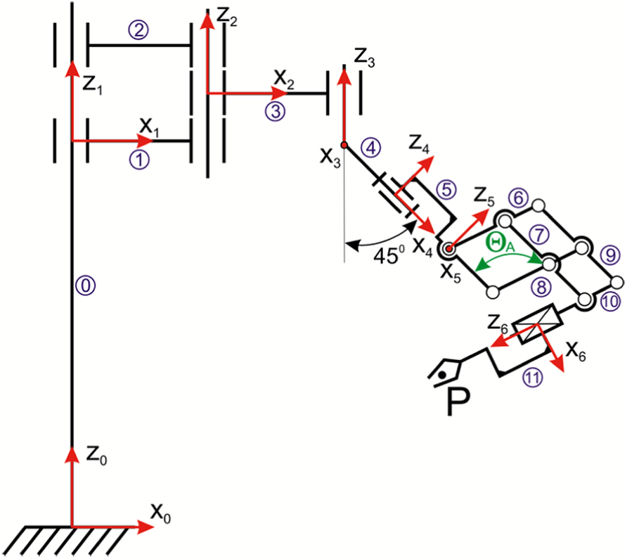
Kinematic structure of a novel surgical telemanipulator.
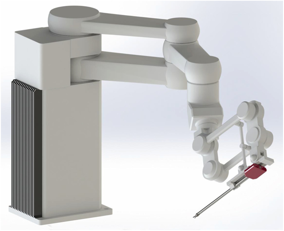
Computer-aided design model of a novel telemanipulator dedicated to minimally invasive surgery.
The presented solution is a modification of the previous version of the robotic arm proposed by Trochimczuk. 28 In the earlier conception of the surgical arm, the active manipulator was based on the classical parallelogram mechanism. It was actuated by three electric drives. Control of the actuators moving the RCM (Remote of Center Motion) mechanism was performed by a mechatronic logic (i.e., using information processing from sensors). In the novel structure of the active manipulator, the number of drives has been reduced to two actuators by adding link 8 (Figure 1). The RCM point is provided by kinematic point fixation. It allowed one to reduce the weight of the active manipulator and simplified its control. This provides a relatively simple solution for the forward and inverse kinematics of the surgical telemanipulator, making it possible to create position control for the surgical end-effector. It has a new form of the articulated parallelogram mechanism by adding the new link 8. In the same way, to increase the range of the displacement of the parallelogram mechanism, links 6 and 7 are attached to a different side of links 5 and 9.
These modifications allow for reducing the number of telemanipulator drives and increasing the stiffness of the active manipulator mechanism, thus simplifying the control. The stiffness of the parallelogram mechanism guarantees the required accuracy and repeatability of the surgical instrument positioning. The additional link 8 allows for obtaining the RCM point in the kinematic way. This choice simplifies the control algorithm.
The proposed structure of the surgical robot arm may have a wide variety of applications. The main idea is to apply the proposed structure to minimally invasive procedures, since access to the internal organs by the RCM point (e.g., cardiac, colorectal, general, gynecologic, thoracic, and urologic surgery) is required.
2.2. Kinematical analysis of the telemanipulator
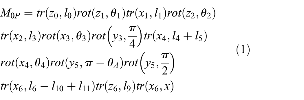
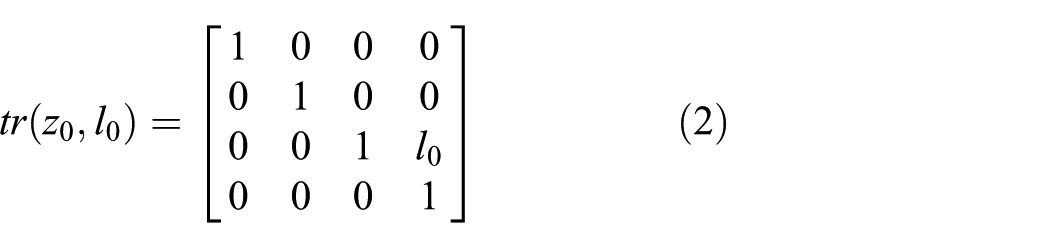
Referring to Figure 1 and according to the double term method, the kinematic equation of the telemanipulator may be written as a set of rotations and translations around/along the axes of the local terms, as shown in (1), where tr(x,y) indicates a translation y along the x-axis and rot(x,y) indicates a rotation y around the x-axis.
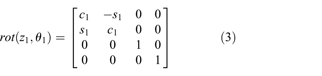
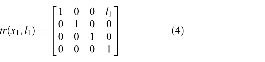
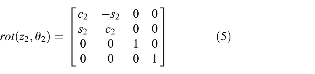
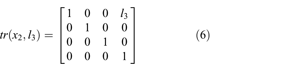
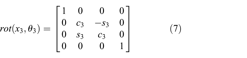
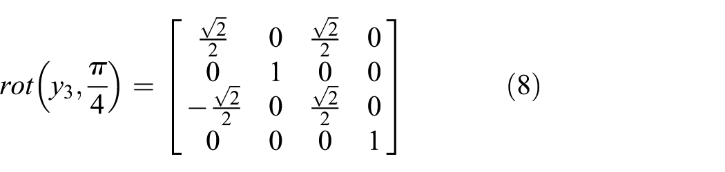
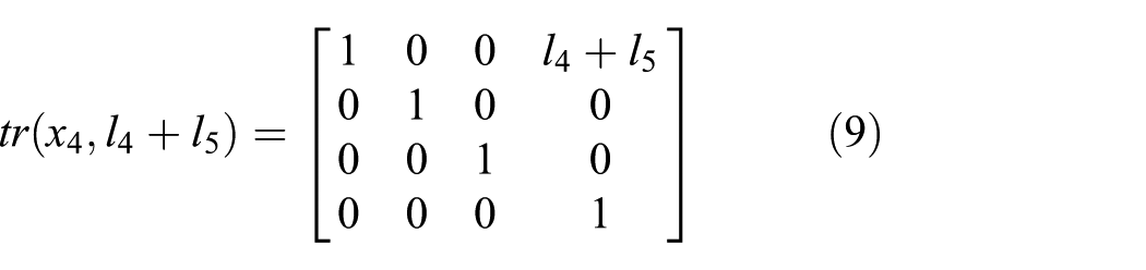
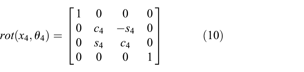
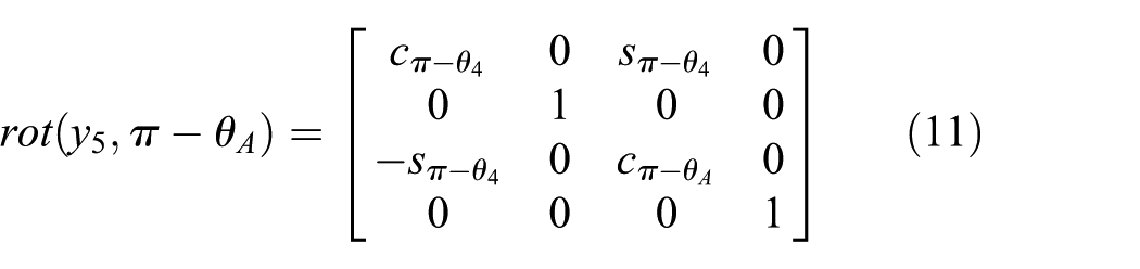
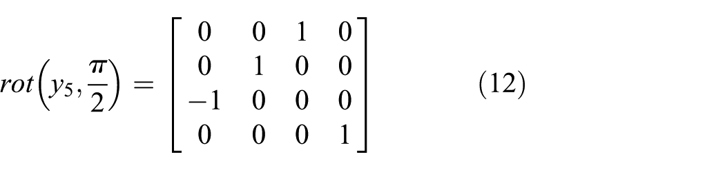
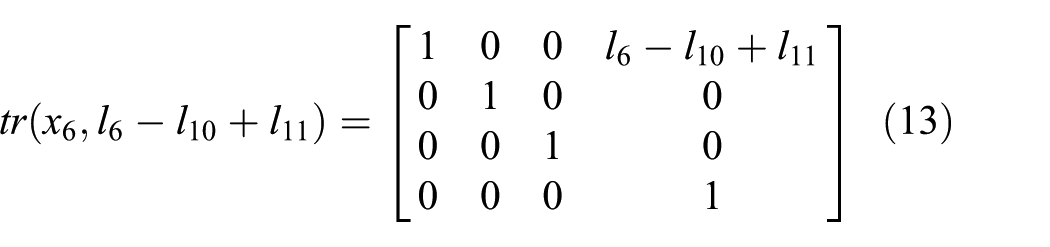
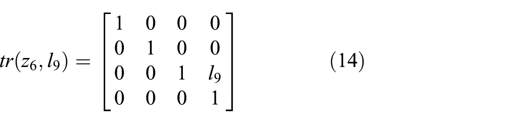
The translations and rotations mentioned in (1) are indicated in (2)–(14), where ci and si represent, respectively, the cosine and the sine of the angle θi, then li indicates the ith link:
Thus, the kinematics of the manipulator (1) may be rewritten in terms of the rototranslation matrixes Ai and Qi, as shown in (16):

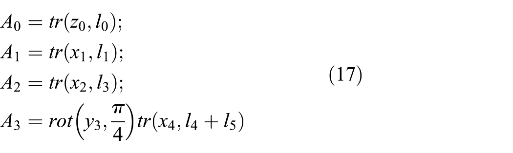
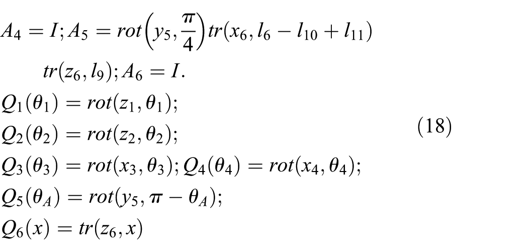
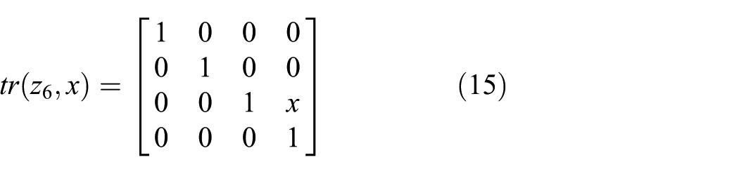
In fact, two terms are present on the ith link: the term (i) indicated in Figure 4 with xiyizi axes and the term (i’) that is rototranslated with the origin that coincides with the term (i+1) and x’iy’iz’i axes. Their position is described by the constant rototranslation matrix Ai (17). Furthermore, the position on the term (i) with respect to the term (i–1)’ is the described by the rototranslation matrix Qi that depends on the joint variable qi (18). In (17) and (18), Ai matrixes are defined without referencing the (i’) terms to avoid an “iper-notation.” The six degrees of freedom (DOFs) of the manipulator are described by the joint variables θ1, θ2, θ3, θ4, θ5, x, as shown in (18).
This analysis permits one to evaluate the workspace of the proposed system and to understand the potential applications, as shown in the next section.
2.3. Stiffness finite element method analysis of passive links of the telemanipulator arm
The passive manipulator of the surgery system is the most important factor that contributes to the stability of the active robot. The stiffness of the structure of the passive manipulator largely depends on the accuracy of the positioning of the active manipulator and the surgical instrument. Therefore, a numerical analysis is required to optimize the constructed solutions and ensure high-quality positioning in the surgical system. In this section the stiffness of links of the passive telemanipulator are analyzed. The finite element method (FEM) and SolidWorks Simulation software (CAE) have been used. The passive telemanipulator has been modeled as assembly in the SolidWorks MCAD system. 33 It includes four components (links 1–4), as shown in Figure 1.
In this context, some simplifying assumptions are adopted. CAD models of links 1–3 are thin-walled in the middle section with thickness of 5 mm (Figure 3). To simplify the finite element (FE) discretization of the CAD model, fillets, and chamfers of edges have been deleted. The active manipulator equipped by the laparoscopic tool is defined as one solid body, having one characteristic position (axis Z6 is perpendicular to axis Z5). It is in a fixed position relative to link 4 (plane X4Z4 is in the Y3Z3 plane) (Figure 4). Multibody techniques have been applied to change the CAD model of the active manipulator from the “assembly” to “part” state with a single solid body in order to simplify the FEM analysis model. 34
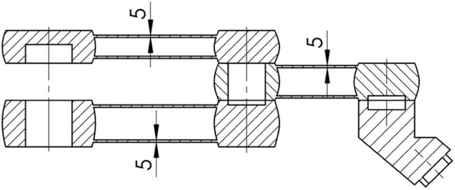
Cross-section of thin-walled links 1, 2 and, 3 of the passive telemanipulator.
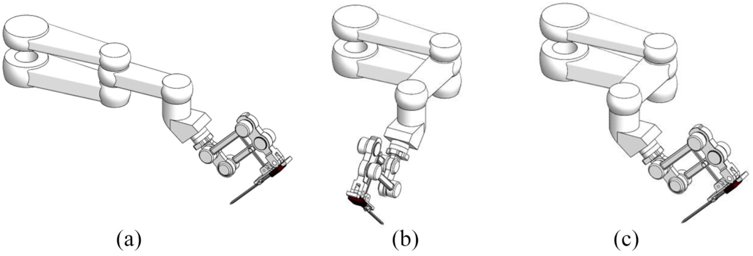
Analyzed positions of the surgical telemanipulator: (a) configuration 1; (b) configuration 2; (c) configuration 3.
Three configurations of the passive manipulator are analyzed (Figure 4) as follows.
Configuration 1: planes X1Z1, X2Z2, Y3Z3 (see Figure 1) are in the XZ plane of the GCS (Figure 4(a)); in this case links, 1, 2, and 3 are only load by bending.
Configuration 2: plane X1Z1 is in the XZ plane of the GCS, planes X2Z2 and Y3Z3 are perpendicular to plane X1Z1 (Figure 4(b)); in this case links 1 and 2 are loaded by bending with torsion, while link 3 is bending.
Configuration 3: plane X1Z1 is in the XZ plane of the GCS, plane X2Z2 is perpendicular to plane X1Z1, plane Y3Z3 is perpendicular to plane X2Z2 (Figure 4(c)); in this case links 1, 2, and 3 are loaded by bending with torsion.
Link 4 is bending in all configurations.
The GCS of the CAD model, which has been used in the analysis, is equivalent to Coordinate System 1 (defined by the rotation of links 1 and 2 relative to link 0), as shown in Figure 5(a). In addition, a local coordinate system (LCS) has been defined. The X-axis of the LCS is compatible with the Z6 axis of the laparoscopic tool (link 11 in Figure 1).
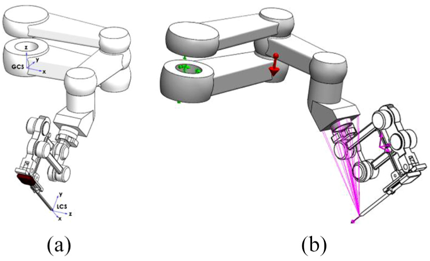
View of the surgical telemanipulator: (a) definition of the coordinate systems; (b) boundary conditions and loadings applied to the passive manipulator.
In order to perform the analysis, a set of assumptions on the boundary condition has been considered. In particular, it has been assumed that the main holes in links 1 and 2 have a fixed geometry. This means that a configuration with six DOFs is equal to 0.
Three cases of loading are assumed (Figure 5(b)) as follows.
Gravity: it is in opposite direction of the Z-axis of the GCS.
Remote Mass: the active manipulator mass properties are used as loads. In this case, bodies that are treated as remote masses are excluded from meshing; nevertheless, their mass properties and moments of inertia are included. For this reason, the active manipulator has been saved as one solid body and used in the assembly for loading passive links. The mass of the active manipulator is 2.53 kg.
Remote Load: force values are equal to 50, 5, –50, and –5 N in the direction of the X-axis of the LCS. These simulated forces are applied on the end-effector.
The program automatically calculates and applies equivalent forces to the selected faces. An applied force of the remote location transfers a force and equivalent moments to the selected faces. The values of the remote loads have been chosen from the state of the art.6,29 These values may simulate real tool loads during the surgical procedures. Remote mass and remote load are applied on the front face of link 4.
The mesh of the FE consisting of 105,217 tetrahedral elements with quadratic interpolation (four vertex and six mid-edge nodes) and 177,757 nodes.
The static and linear-elastic simulations have been performed for 12 cases. The calculated results are based on the maximum Huber–Mises stress, the resultant displacement in the GCS, and the X-axis displacement in the LCS.
The considered material of the telemanipulator passive and active arms is polyether ether ketone (PEEK). It is a colorless organic thermoplastic polymer that is part of the polyaryletherketone (PAEK) family. This material is used in engineering and biomedical applications. The parameters of PEEK used in the numerical analysis are as follows: Young’s modulus – 3.9 GPa; Poisson’s ratio – 0.4; density – 1.310 kg/m3; tensile strength – 95 MPa; compressive strength – 125 MPa.
2.4. Results
Considering the presented configuration of the kinematic scheme, an analysis of workspace was carried out. It is an important kinematic indicator that is used to change the position and orientation of surgical instruments. Exact knowledge of the shape, dimensions, and structure of the robot workspace is important for defining and testing new surgical procedures in the space where the robot can work inside the patient’s body. The view of the shape and volume (see dimensions) of the workspace, in the case when active manipulator is fixed in position – link 5 is perpendicular to link 6 in the parallelogram mechanism, is presented in Figure 6. 35
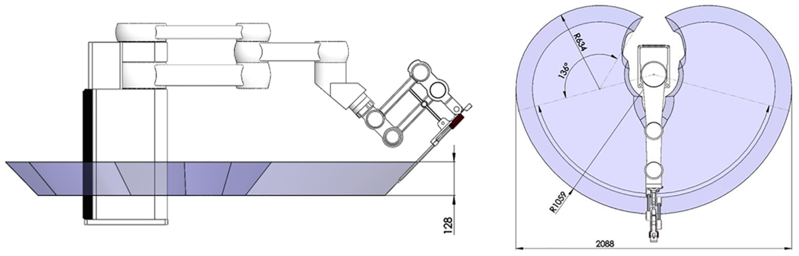
View of the workspace of the novel telemanipulator dedicated to minimally invasive surgery.
The results of FEM computations are presented in Table 1.
Results of analyses for three configurations with loads: gravity, remote mass, and remote loads applied in positive and negative directions of the X-axis of the local coordinate system (LCS).
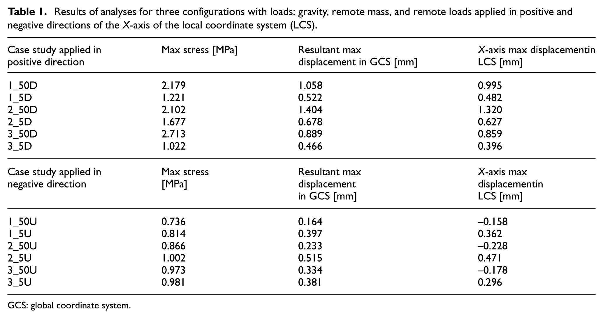
GCS: global coordinate system.
The following symbols were used in the description of each case study:
telemanipulator arm configuration;
load value;
direction of loading.
For example, notation “1_50D” means the following:
1 – configuration case (see Figure 4(a));
50 – load 50 N;
D – load in the positive direction of the X-axis of the LCS.
The notation “D” (Table 1) indicates that the remote load has been assumed as “Down” in the positive direction of the X-axis of the LCS. Meanwhile, letter “U” (Table 1) shows that the remote load has been considered as “Up” in the negative direction of the X-axis of the LCS.
The results obtained from the finite element analysis (FEA) show that the maximum resultant displacements do not exceed 1.5 mm in all considered cases. The absolute differences between the values of resultant displacements in the GCS and maximum X-axis displacement in the LCS are no greater than 10%. When the remote load is applied in the positive direction of the X-axis of the LCS (Table 1), and the directions of the vertical load components (gravity, remote mass, and remote loads) are congruent, the displacement values increase when the remote load is in the negative direction of the X-axis of the LCS.
In the second case, the effect of kinematic chain offloading is considered. The direction of the vertical component of the remote load is opposite to the directions of gravity and remote mass. It causes negative values of X-axis displacement in the LCS for all three configurations loaded by remote force equal to –50 N (studies 1_50U, 2_50U, 3_50U in Table 1). This case is the most adverse condition (2_50D) due to the stiffness of the passive manipulator, since the value of the X-axis displacement in the LCS is equal to 1.32 mm. In particular, the difference between the values of the maximum X-axis displacement of the LCS of 2_50D and 2_50U conditions is the largest of all analyzed scenarios, and it is equal to 1.548 mm.
In the same way, if the remote load is applied in the negative direction of the X-axis of the LCS (Table 1) the most adverse condition is 2_5U, where the value of X-axis displacement in the LCS is 0.471 mm.
The results from Table 1 were presented as bar charts (Figure 7) in order to better illustrate and compare the results of FEM analyses.
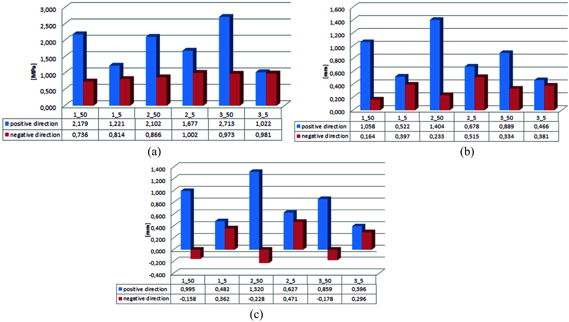
Results of (a) the maximum stress value versus the case of study analyses, (b) maximum resultant displacement in the global coordinate system versus the case of study analyses, and (c) X-axis displacement in the local coordinate system versus the case of study analyses.
Figure 8 presents the results of the X-axis displacement in the LCS for the second configuration and case study 2_50D and 2_5U. These cases are the worst in stiffness, namely: 2_50D for the positive direction and 2_5U for the negative direction.
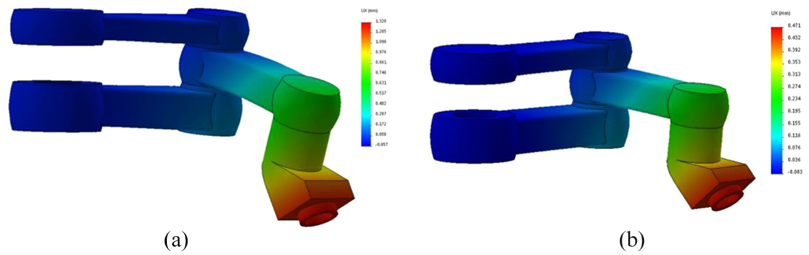
The results of X-axis displacement in the local coordinate system for configuration 2 (scale of deformation – 100):(a) case 2_50D; (b) case 2_5U.
The best results, taking into consideration the stiffness of the passive manipulator, were obtained in the third configuration. However, the range of the passive manipulator is lower than in the first configuration. In addition, the obtained values of the X-axis displacement in the LCS are lower than in the first configuration by 16% and lower than the second configuration by 54%. In this case the remote load is assumed equal to 50 N and applied in the positive direction of the X-axis of the LCS (Table 1). Furthermore, when the remote load is equal to 5 N, the obtained values in the third configuration are lower than in the first and second configurations by 21% and 58%, respectively.
Considering the remote load applied in the negative direction, the third configuration absolute values of the X-axis displacement (Table 1) are greater than the first configuration by 11%, while they are lower than the second configuration by 22% (50 N). When the remote load is 5 N, the obtained results of the third configuration are lower that the first and the second conditions by 22% and 59%, respectively.
Figure 9 presents the results of Huber–Mises stresses and places of their maximum values. The second configuration and case studies 2_50D and 2_5U are considered as in Figure 8.
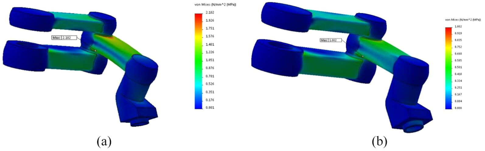
The results of Huber–Mises stress for configuration 2 (scale of deformation – 100): (a) case 2_50D; (b) case 2_5U.
The stress values of the analyzed case studies do not exceed 3 MPa (Table 1). The values of stresses and displacements are dependent on the material properties and geometry of the links. An increase of the stiffness is possible by changing the wall thickness and redesigning the internal structure of links (e.g., ribs, honeycomb, etc.). The presented results will be used in future works focused on the surgical telemanipulator system development. In particular, the kinematic and dynamic analysis, including singularity of the arm position of the telemanipulator, will be improved.
The reaction and inertial forces of movement of the active manipulator will be applied to create new numerical simulation models. The obtained results will optimize the structure of the telemanipulator and the development of the prototype. It is possible to use the new solution of robot structure with a 2 DOF effector 36 or to implement parallel kinematics.37,38
3. Discussion
This paper aims at presenting a novel telemanipulator for MIS. Starting with the solid model of the robot, the results of the numerical study on the proposed device are discussed, focusing on the influence of the geometric parameters of the kinematic chain on the displacement accuracy of the end-effector. The main guidelines are as follows.
The quality of positioning also depends on the following:
smoothness – this is the parameter associated with the movement of the telemanipulator with an endoscopic instrument (e.g., grasper, scalpel, coagulant, endoscopic camera, etc.), movement of the surgical table, and the transmission of video images from the surgical field to the master surgical console (image processing is an additional component of the positioning feedback);
accuracy – this allows for moving the instrument in steps of 0.1 mm, maintaining the scalability of movement, mirroring movements of the surgical instrument, and positioning the surgical table;
repeatability – this is an important parameter for the purpose of maintaining the RCM point of the surgical laparoscopic instrument.
The stiffness of the structure is a very important factor to be considered in designing a surgery telemanipulator with accurate positioning of a surgical instrument. The structure stiffness increase is possible by changing the wall thickness and designing a more complex internal structure of the telemanipulator links (e.g., ribs, honeycomb, etc.). The use of numerical methods may optimize the construction of the robot arm, considering the different states of loads and adopted positions.
4. Conclusions
The proposed structure of the robot arm allows the implementation of many common surgical procedures through the fixed RCM point in the patient’s body. To the authors’ knowledge, the arm has a new, unique structure. The surgical robot kinematics solution proposed in the paper will become the basis for the development of a fully functional laboratory prototype, which will be subjected to further research.
The quality of the positioning of the surgical robot subsystems depends mainly on the stiffness of the telemanipulator (e.g., the stiffness of the passive and active manipulator) and the operating table. Positioning errors should be taken into account using a control algorithm. The results of numerical analysis and simulation should be applied in this algorithm.
Footnotes
Acknowledgements
This paper was performed within the framework of S/WM/1/2016 and S/WM/1/2018, realized in Bialystok University of Technology. Some ideas were made with the collaboration of researchers from the University of Science and Technology (Bydgoszcz, Poland) and Università degli Studi di Brescia (Italy).
Funding
This work was supported by the Ministry of Science and Higher Education of Poland.