
Abstract
Understanding the dynamics of complex systems requires developing and combining different kinds of models that can be simulated separately and together. Modeling the interactions as separate models contributes to building flexible hybrid simulation frameworks. In this research, a Discrete Event System Specification–based Interaction Model (DEVS-IM) framework is developed based on the Knowledge Interchange Broker (KIB) approach. This KIB-based RESTful modeling composition framework is shown to enable systematic modeling and simulation of interactions between disparate simulatable models. It supports storing IMs developed for componentized Water Evaluation and Planning System (WEAP) and Low Emissions Analysis Platform (LEAP) tools. It generates the skeleton of DEVS-IMs stored in database for DEVS-Suite simulator. An exemplar model consisting of water, energy, and IMs demonstrates this methodology for developing nexus models of water–energy systems.
Keywords
1. Introduction
Modeling the connections in hybrid simulations contributes to simulation-based understanding, development, and operation of heterogeneous systems. The complexity of such system-of-systems spans structure and behavior at the individual and combined resolutions. Among the key attributes of such systems are hierarchy, choice of components, and their linkages characterized, in part, as interaction frequencies. 1 The systems affect one another as influencers and influences, thus resulting in a nexus which by itself is a system with varying degrees of abstraction. It is straightforward, for example, to observe a water system consisting of groundwater and rivers while an energy system consisting of fossil fuel, wind, and solar. The users of such water–energy systems include individuals, households, and industries forming municipalities with varying needs under many supply and demand scenarios. As systems-of-systems, water, energy, and interaction systems can have different kinds of structure and behavior exhibiting simple to complex dynamics at varying scales. 2
The above indicates that the development of large, complex models should be simpler and scalable when they are built from smaller, less complex models. Various concepts and methods exist for constructing whole models from parts.3,4,5,6 It is beneficial and even necessary to use distinct modeling methods when the scope of simulation studies expands. It is well understood that models should be developed according to concise composition and decomposition methods. The methods can be broadly categorized to be homogeneous and heterogeneous. In the former, composed models have identical structure and behavior. In the latter, the composed models have distinct structures and behaviors. Heterogeneous models commonly have continuous- and discrete-time models.
Practitioners and researchers may contemplate questions of interest on one part of a system-of-systems at high resolution while the other parts interact with it at low resolution. This approach is attractive as some of the parts that affect or are affected by others are simplified relative to others. This approach can significantly restrain overall model scale and complexity, for example, by replacing the dynamics of some systems as input and output time trajectories. Considering the water–energy systems, the amount of available photovoltaic energy can be modeled as a piecewise constant variable in modeling a water system. The photovoltaic system can be modeled to have fluctuating power production under different conditions such as demand at different times of the day.
With the above in mind, understanding the inner workings of a system-of-systems entails developing models that consist of parts and connections. Therefore, it is necessary for the models developed in one method to be combined with others developed using other methods. The models developed may belong to the same model type but are used in separate simulation engines. Some existing frameworks and their tools are quasi-component-based from the strict modularity and hierarchical composition standpoint. A modular model has input and output interfaces with concise structural and behavioral specifications. The interfaces allow relationships between disparate models to be formalized in terms of separate data, control, and time specifications.
The Water Evaluation And Planning (WEAP) system can be used to model and simulate the usage of water for consumption. 7 In this system, the input and output variables are shared variables among model elements. External inputs and outputs to/from the models can be defined as written using script or other programming languages. Such languages can be perceived to have input and output interfaces, but they are not modeling languages. Similarly, energy usage can be modeled and simulated using the Low Emission Analysis Platform (LEAP) system. 8 The relationship between the water and energy systems forms a nexus, thus being a system just like the water and energy systems.
Different parts of the WEAP system and the details of the design and development of the componentized WEAP RESTful framework are presented in detail in previous work. 9 An overview of the framework, from communication perspective, is presented in section 4.2. The same approach for componentized WEAP is applied for the LEAP system. The componentized WEAP and LEAP RESTful frameworks offer a foundation for the underlying intricacies and structure of WEAP entities through proxy component models. The componentized frameworks use the same schema for a project, its scenarios, entities, and every entity’s input/output variable. As the first attempt to develop a framework for the interconnection between water and energy systems, an Algorithmic Interaction Model (Algorithmic-IM) framework was developed based on the Knowledge Interchange Modeling (KIB) approach and object-oriented principles. 10 This IM lacks a sound, system-theoretic basis for formally specifying the interactions between water and energy models. As the second attempt, an IM (called Discrete Event System Specification–based Interaction Model (DEVS-IM)) based on the KIB approach, parallel DEVS formalism, and system-of-systems approach was developed for the class of WEAP and LEAP models. 11 The result is the RESTful framework that supports composing water, energy, and IMs and simulating them enabled by componentized WEAP, componentized LEAP, and DEVS-Suite simulator. 12
Previous papers explained the design and implementation of the frameworks (componentized WEAP, Algorithmic-IM, and DEVS-IM) to define an IM for the water–energy nexus. This article focuses on the DEVS-IM framework communication with simulatable models. Along with explaining the conceptual approach in the rest of the paper, it will be also explained how to start from a simple water–energy model, develop them in the WEAP and LEAP systems, extract the water and energy parts/components that have significant roles in the IM, develop the DEVS-IM model, and finally, run the simulation for the Water-Engery Nexus (WEN) model. The contributions of this paper, excluding those published in earlier venues, are (1) the DEVS-IM framework that enables design and development of IMs with a generic ontology for the disparate external systems, (2) an abstract structure with elements and a process to define specific kinds of DEVS-IMs, (3) developing an exemplar water–energy with nexus IM, and (4) a detailed formulation of the DEVS-IM communication with the componentized WEAP and LEAP systems.
In the following, sections 2 and 3 briefly cover water–energy systems, Knowledge Interchange Broker (KIB), parallel DEVS, and service-oriented architecture (SOA). Section 3 focuses on closely related works, frameworks for modeling and simulation of water–energy systems, and an exemplary water–energy nexus model. Section 4 presents the architecture and design of the implemented KIB-based interaction modeling and simulation in detail using the exemplar system. Sections 5 and 6 offer a discussion and conclusion, respectively.
2. Background
2.1. Water and energy systems
The water and energy demand and supply are often managed separately, but policymakers and resource managers need to understand the interaction amount competing water and energy needs. Understanding the nexus (interaction) between water and energy is necessary for their better use, production, and management. 13 By the end of this decade, it is expected the need for water to increase by 12% 14 and energy by 14% 15 compared to the 2019 demands, mainly because of the increase in population, urbanization, climate change,16,17 and resource availabilities.18,19 These systems have several bidirectional dependencies. For example, water is needed to cool power plants for energy generation, and energy is required for water treatment. In addition, climate change, population growth, and economic instabilities also contribute to the complexities of the systems. The linkages among the systems need to be modeled, simulated, and evaluated to identify, develop, and implement decisions that can account for the possible impacts these systems have on one another.
It is advantageous to use existing frameworks/tools such as WEAP and LEAP systems for simulating water–energy systems. They may reduce the effort and resources for model development. It also allows for better use of previously acquired domain knowledge and experience. The case study in this research is based on using the WEAP system to model, simulate, and evaluate the water system and the LEAP system to track energy consumption, production, and resource extraction of the energy system. Water and energy models are used as supply and demand entities. The models define the allocation of water and energy from different sources through preferences and mass balance constraints.
Both WEAP and LEAP systems have a scenario-based approach, and their entities have predefined input and output variables. Even though the water and energy input and output variables are known, the mass balance equations are not, and the interconnection between the entities and their variables is unobservable from the outside world. The variables for the entities appear to be shared within a system and between the systems given using the WEAP–LEAP internal linkage mechanism (see section 3.1). All the WEAP and LEAP input data must be available prior to the start of being used in model execution, and all output data will be accessible after the execution completes. Most of the calculations in the LEAP are computed on an annual time granularity (except for some variables that run on time-slice units for a year). A year in the WEAP system is divided into n equal time steps (see Fard and Sarjoughian 10 for more details).
2.2. Knowledge Interchange Broker
Model composition methods from a system-theoretic standpoint can be classified into four types: mono-, super-, meta-, and poly-formalism. 20 Each method ensures that the interactions among composed models have well-defined structural and behavioral specifications. Considering homogeneous modeling, in a mono-formalism method, different parts of a system are modeled via a single formalism, such as Discrete Time System Specification. 5 The single formalism (one syntax and semantics set) is used for multiple models. In the super-formalism approach, models developed in distinct but closely related modeling formalisms are combined in a model that conforms to another formalism. 21 An example is approximating continuous to discrete-event models. 22 In the meta-formalism method, not closely related formalisms are transformed into another modeling formalism. An example is the Actor model of computation 23 used for combining different types of functional, sequential, and (untimed and timed) concurrent models. 4 In the poly-formalism method, one or more models, developed with distinct modeling formalisms, are composed of another model that has its modeling formalism. This formalism accounts for the differences between the syntaxes and semantics of the composed modeling formalisms. 24
The KIB abstraction based on the poly-formalism method specifies the interactions between the composed models. 20 The conceptual basis of the KIB is that disparities between different model types should be accounted for with a model with its syntax and semantics, thus enabling modular modeling of the interactions between the composed models. The KIB models the interaction between the composed disparate models in terms of data mapping, concurrency, synchronization, and timing (see Figure 1). A key concept for the poly-formalism modeling method is to separate model specification and its execution protocol. The data mapping element involves data (dis)aggregation from one dataset to another dataset, for example, using average calculations and unit conversions. The concurrency specifies simultaneous model executions. The synchronization specifies the interaction modes among composed models as sequential, synchronous, and asynchronous. The timing specifies managing the timescales used in the models that are composed.
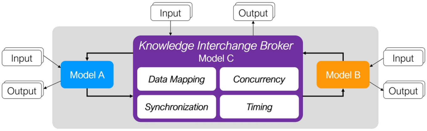
The KIB model for creating IMs.
2.3. Parallel DEVS formalism with abstract simulator
Using a formal modeling method to model and simulate the interactions between disparate models is advantageous. A component-based, hierarchical modeling approach that aligns with system thinking helps with the development, reuse, and maintainability of IMs. In a discrete-event abstraction, only a finite number of relevant events occur during a bounded time interval. A discrete-event model is characterized by the output events which are generated in response to a series of input events. There is no restriction on the internal state of the model, as the system is seen as a “black box.” 25
The Parallel DEVS is a system-theoretic formalism for modeling complex dynamical systems.11,5 Its system-theoretic foundation supports modular and hierarchical model construction.25,26 The term “DEVS” is used in the rest of the paper, referring to the parallel DEVS formalism. Models are defined as a combination of atomic and coupled models. Atomic models are specified as
Coupled models are specified as
The atomic and coupled models can be executed using abstract atomic and coupled simulator protocols. 27 A DEVS simulator implementing the protocols has a strict hierarchy mirroring the atomic and coupled DEVS models. An atomic simulator corresponds to each atomic model, a coupled simulator corresponds to each coupled model, and a root coordinator manages the execution of the coupled simulators.
The DEVS models can be developed and simulated using the open-source, object-oriented DEVS-Suite simulator. 28 It is developed using the Model Facade View Control (MFVC) architecture.29,30 It supports describing complex structures and behaviors of systems using object-oriented modeling techniques and advanced features of the Java programming language. The simulator supports a range of visualization and data storage features, including PostgreSQL database, automated data (input, output, and state) collection, input/output message animation, and linear/superdense run-time data trajectory. 28 This DEVS formalism with its abstract simulation protocols (supported with the DEVS-Suite simulator) is used for developing IMs for the KIB-based RESTful modeling composition framework.
2.4. Service-Oriented Architecture
Service-Oriented Architecture (SOA) is a technology-neutral, platform-independent development framework that provides the aspects of reusability, agility, loose coupling, and interoperability with the help of a collection of services. 31 Nowadays, there are two main web service protocols: the Simple Object Access Protocol (SOAP) 32 and the REpresentational State Transfer (REST). 33 The former is an Extensible Markup Language (XML)-based standard communication specification over a particular protocol, such as Hypertext Transfer protocol (HTTP) and Simple Mail Transfer Protocol (SMTP). The latter is a web-based architectural style with flexible message formats, such as XML and JavaScript Object Notation (JSON). From the client’s perspective, the SOAP is based on the operation/method, whereas the REST is based on the resource. The RESTful framework implements the REST architecture based on the HTTP protocol. 34 Asynchronous requests, higher security and reliability, and error reduction are the main reasons for choosing the SOAP standard. Greater scalability, compatibility, performance, and simplicity are the common reasons for choosing the REST standard. 35
3. Related work
Combining models defined using different modeling methods is studied extensively. A comprehensive collection of methods is formulated as Models of Computation using the Actor Model. 4 Models are classified as functional, sequential (event graphs and state machines), and (un)timed concurrent. The untimed models are further classified as rendezvous, process networks, dynamic dataflow, and synchronous dataflow. The timed reactive models are classified as continuous-time and discrete-event. There exist other methods commonly used for combining continuous and discrete models.36,37,38 Some of these methods are further extended to support other kinds of modeling methods.39,40,41 There also exists a large body of work for integrating simulation models using middleware software technologies supporting distributed simulation. A prominent framework is the High-Level Architecture 42 with the Object Model Template 43 and Base Object Model 44 standards. More broadly, model composability and simulation interoperability are complementary and supported by a variety of methods, frameworks, tools, and practices. 45
Many tools/frameworks have been developed to model and simulate the combined natural and built systems. These can be roughly categorized into resource-environmental footprint quantification models to quantify the resource and economic efficiency (e.g., Urban Water Optimization Tool (UWOT) 46 and Regional Energy & Water Supply Scenarios (REWSS)) 47 , performance evaluation of the natural-built systems (e.g., Competitive Markov Decision Process (CMDP)), 48 and optimal management of intricate interacting processes (e.g., Climate, Land-use, Energy and Water Strategies (CLEWS) 49 and WEAP–LEAP).50,8
3.1. KIB-based modeling frameworks
The compositions of simulatable heterogeneous models have been developed for discrete-time and discrete-event, cellular automata, ordinary differential equations, partial differential equations, and constrained-based optimization models. An early realization of the KIB is for parallel DEVS and Composable Cellular Automata (CCA) modeling formalisms.51,24 Socioecological IMs are developed for agent models using DEVS and for the environment using Discrete-Event Composable Cellular Automata (CCA-DEVS). IMs can be developed based on Parallel DEVS restricted to have natural numbers and infinity as time base. The composition of agent, landscape, and IMs is applied to studying long-term human landscape activities and evolution. 52
In another research, the Geographic KIB (GeoKIB) introduces spatially based interactions among models. 53 Two independent models may have data associated with any two-dimensional geographic data maps. GeoKIB specifies data transformation between any two regions, each having different map cell sizes and boundaries. This kind of interaction modeling specifies discrete-time spatiotemporal data transformations belonging to discrete-time cellular automata models and discrete-time synchronous reactive models. The cellular automata map data may change by any agent that is assigned to any cellular automaton. Input/output for GeoKIB can be time-synchronized or not. GeoKIB is designed using object-oriented principles and methods and implemented in Java.
Also, a CCA-DEVS framework is developed for discrete-time CCA and parallel DEVS models at the I/O level. 54 In this framework, supported in the DEVS-Suite simulator, 28 DEVS-based agent and ordinary differential equation (ODE)/ partial differential equation (PDE) models are composed. In particular, the simulator supports run-time component-based animation, run-time spatiotemporal 2D visualization, and linear/superdense input, state, and output time trajectories for the DEVS and cellular-based ODE/PDE models. The ODE and PDE models are supported using OpenModelica and others. This approach can help better understand cell-to-cell and CCA-to-CCA interactions. This KIB uses GeoKIB to compose CCA models having different distinct temporal and spatial scales. The interactions in the CCA-DEVS framework are modulated in terms of spatiotemporal data transformations, control schemes, and distributed execution.
An Algorithmic-IM framework was developed based on the KIB approach and object-oriented principles to couple the componentized WEAP and LEAP models. 10 In the Algorithmic-IM, two levels of Module and Transformation structured elements define a separate model for the interactions between the water and energy models. The framework has a cyclic, fixed, discrete-time synchronous execution protocol. The data transformations are handled in the transformation elements. The outcome was a concurrent and bidirectional IM for data mappings between the water and energy models. However, this IM does not separate model specification from its execution protocol (a fundamental principle of the KIB modeling approach for model composability). This KIB has four significant constraints: (1) one level of the hierarchy can be used to define the IM structure (i.e., modules in the first level and transformations in the second level), (2) the model structure and execution protocol are interwoven in the Algorithmic-IM design and implementation, (3) the execution protocol is fixed (six sequential steps), and (4) finally, the structure and behavior of the model must be defined via programming language (i.e., Java programming language).
An early realization of the KIB approach was developed for the DEVS, model predictive control (MPC), and linear programming (LP) formalisms and demonstrated for Intel’s semiconductor supply-chain system.55,56 This framework provides a set of suitable message mappings and transformations. The execution of the models and their KIB are supported with a parallel a/synchronization protocol. DEVSJAVA, the DEVS-Suite predecessor, MATLAB, OPLStudio, and CPLEX are the tools. The IM’s data transformations are devised as time-based XML with implementation in Java. This KIB is extended with hierarchical XML schemas for large-scale IM specification. 57
3.2. Service-oriented simulation
A comprehensive study highlighting the benefits and uses of service-oriented simulation for distributed modeling and simulation. 58 The study proposed a three-dimensional reference model as a systematic framework for understanding and comparing various service-oriented simulation approaches. Also, simulation as services, service coordination, quality of service (QoS), and software engineering principles are also presented. A unifying methodology/framework is also designed to facilitate the development and management of complex simulations by encapsulating simulation components as services, enabling their modular composition to build more extensive and adaptable simulation systems. The authors emphasize the advantages of this service-oriented approach, highlighting its potential for creating modular and reusable simulation components that can streamline the development and maintenance of intricate simulations across various domains. 58
Regarding the use of the REST approach with distributed simulation, the RESTful-CD++ middleware leverages RESTful web services to expose simulation resources through hierarchical Uniform Resource Identifiers (URIs), allowing for interoperability across heterogeneous simulation components. 59 Users’ data and simulation services are organized in a structured database, and HTTP methods are used to access and manipulate these resources. The middleware integrates CD++ simulation engines for distributed simulation, facilitating seamless modeling reconfiguration and partitioning. Performance tests demonstrate the middleware’s stability and efficiency, even under high concurrent load. By standardizing simulation semantics through XML messages and RESTful web services, this framework offers a flexible and accessible solution for distributed simulations, simplifying both client and server implementations.
Other research focuses on the interoperability among DEVS simulators and simulation frameworks via web services. An automatic DEVS interface for web services (named DEVSI4WS) to enable formal modeling of web services is presented in the work by Seo and Zeigler. 60 The interface converts web services into DEVS models, with a focus on enabling dynamic testing and interoperability among Business Process Execution Language models implemented by different vendors. A tool is developed to support the users to integrate, execute, and simulate web services. In another research, focusing on DEVSJAVA (Java) and ADEVS (C++) simulators, web services were created for each implementation and enable them to communicate seamlessly and exchange information. 61 To ensure interoperability, DEVS messages were transformed into XML-style messages for neutral message passing between the different languages and platforms. The study introduces an interoperable message conversion mechanism, particularly in the context of DEVSJAVA and ADEVS. The resulting system successfully integrates these DEVS simulators, allowing for coordinated simulation of complex models. 61 A service-oriented simulation framework is developed based on High-Level Architecture (HLA)/ Run-Time Infrastructure (RTI) with support for model specification akin to actors, templates, and code generation, model checking, and service-oriented multi-agent simulation. 62
3.3. Water–energy system modeling and simulation
In recent times, there has been a notable surge in the exploration of the water–energy systems. The quantity of research efforts and the capacity of the scientific community to evaluate this subject have been increasing, primarily driven by the intention to gain a deeper comprehension of the intricate interaction between water and energy systems. One study scrutinized 35 distinct methods, tools, and frameworks pertaining to the water–energy systems, taking into consideration factors, such as geographical scale and the scope of the interconnections. 63 This study focused on the intricate interplays between water, energy, and other interconnected aspects, such as the environment, food, land, and climate.
Considering simulation studies of integrated water and energy systems (with other systems, such as food and climate), frameworks/tools such as Precipitation Runoff Modeling System (PRMS) 64 and WEF Nexus Tool 2.065 have been developed. These tools are not based on component-based modeling principles and service-oriented computing. The PRMS is a deterministic, distributed parameter, physical process–based modeling system developed to evaluate the impacts of various climate and land use combinations on surface-water runoff, sediment yields, and general basin hydrology. The WEF Nexus Tool 2.0 is a scenario-based tool for guiding resource allocation at the country level for a given level of food self-sufficiency and a set of technologies, land uses, and resource availabilities. The Climate, Land, Energy, and Water (CLEW) framework is based on a system’s approach to analyzing interactions between interconnected sectors. 66 It uses existing simulation tools (WEAP, LEAP, and Agro-Ecological-Zoning (AEZ)) based on a modular structure to illustrate synergies and tradeoffs within the CLEW areas for decision-making related to achieving development goals. 49 The CLEW framework applies to different geographical scales from global to regional, national, and urban levels. 67 Tools with higher complexity scores (e.g., CLEW, WEAP, and LEAP), unlike those with lower complexity scores (e.g., WEF Nexus Tool 2.0), can capture details for specific resource interactions, whereas they are unable to cover a larger number of interactions and system components, simultaneously. 68
From a model coupling perspective, the WEAP and LEAP systems have an internal linking mechanism established in 2012 that can bidirectionally share data to read variables from one to another. Domain experts and researchers widely use the coupled WEAP and LEAP tools for WEN analyses. 49 The WEAP and LEAP models’ scenarios and time granularities must be mapped for given projects. Some restrictions must be satisfied for this connectivity. First, both projects must have the same start and end year for the simulation. Second, both projects must have a matching set of timesteps, for example, monthly or daily. 10 Third, WEAP and LEAP systems must be installed on the same machine. Fourth, the WEAP and LEAP tools must be executed manually and sequentially. After coupling the WEAP and LEAP systems, they can bidirectionally share data. Nevertheless, users must know all details of the defined water and energy models in the WEAP and LEAP systems. Any changes in one system need strict consideration in the other system. The following water–energy model is used in the remainder of this paper.
3.4. Exemplar water-energy nexus model: Part A - conceptual
The example presented in Figure 2 illustrates a schematic of the water and energy entities (models) for a simple water–energy system. Given the necessity of understanding, making, and supporting decision policies, the water and energy models satisfy some primary constraints individually and relative to one another. In Figure 2, the “Farm” needs 0.2
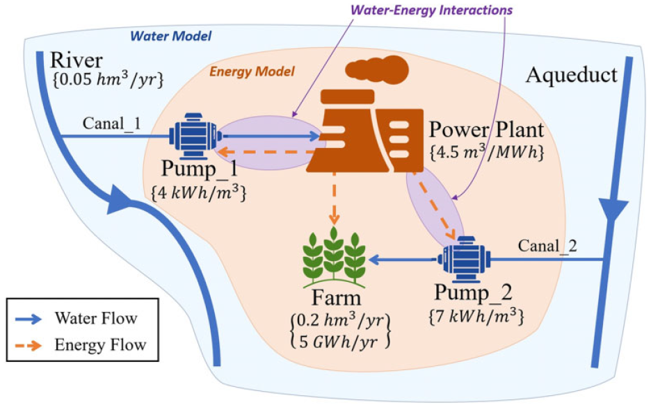
A schematic view of a water and energy system and their interaction.
Suppose having seasonal time granularity for the water and yearly time granularity for energy. Equations (1), (2), and (4) show the data transformations for the models which form the combined constraints for the interactions between the water and energy systems. The year property can be between the start-year and end-year. The required energy for “Pump_1” equals the sum of the Flow in “Canal_1” in all seasons of a year, multiplied by 0.004 (see Figure 2). The same equation is used for the required energy in “Pump_2,” but with a different constant factor (i.e., 0.007). Equation (4) shows that the water required for the “Power Plant” is calculated by multiplying the generated electricity in a year by 4.5 (see Figure 2):
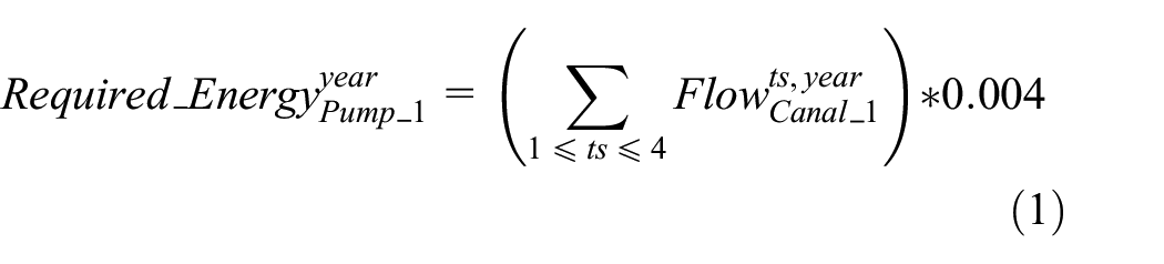

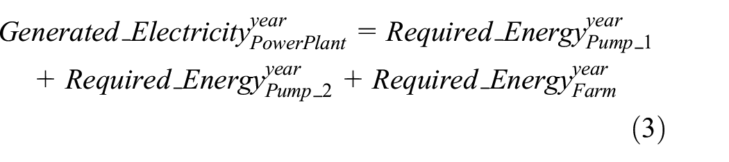
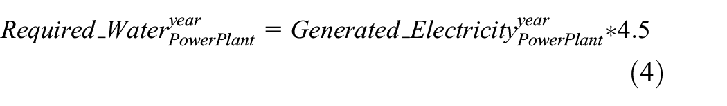
Figure 3 illustrates the developed models in the WEAP and LEAP tools for the water–energy system in Figure 2 (suppose ignoring the different time granularity in the systems and using the WEAP–LEAP internal linkage). The water model has two River, two Transmission, and two Demand Site entities. The energy model has one Resource, one Transformation, and three Demand entities. The solid blue (Flow values) and dotted orange (Electricity values) arrows between the water and energy models are the interconnection among the systems (without using a separate IM). The “PowerPlant” demand site entity in the WEAP model needs to know the amount of generated Electricity by the “PowerPlant” transformation entity in the LEAP model. The “Pump1” and “Pump2” demand entities in the LEAP model need to know the amount of Flow in the “Canal1” and “Canal2” transmission link entities in the WEAP model. The required amount of water for the “Farm” demand site entity in the WEAP model (which is
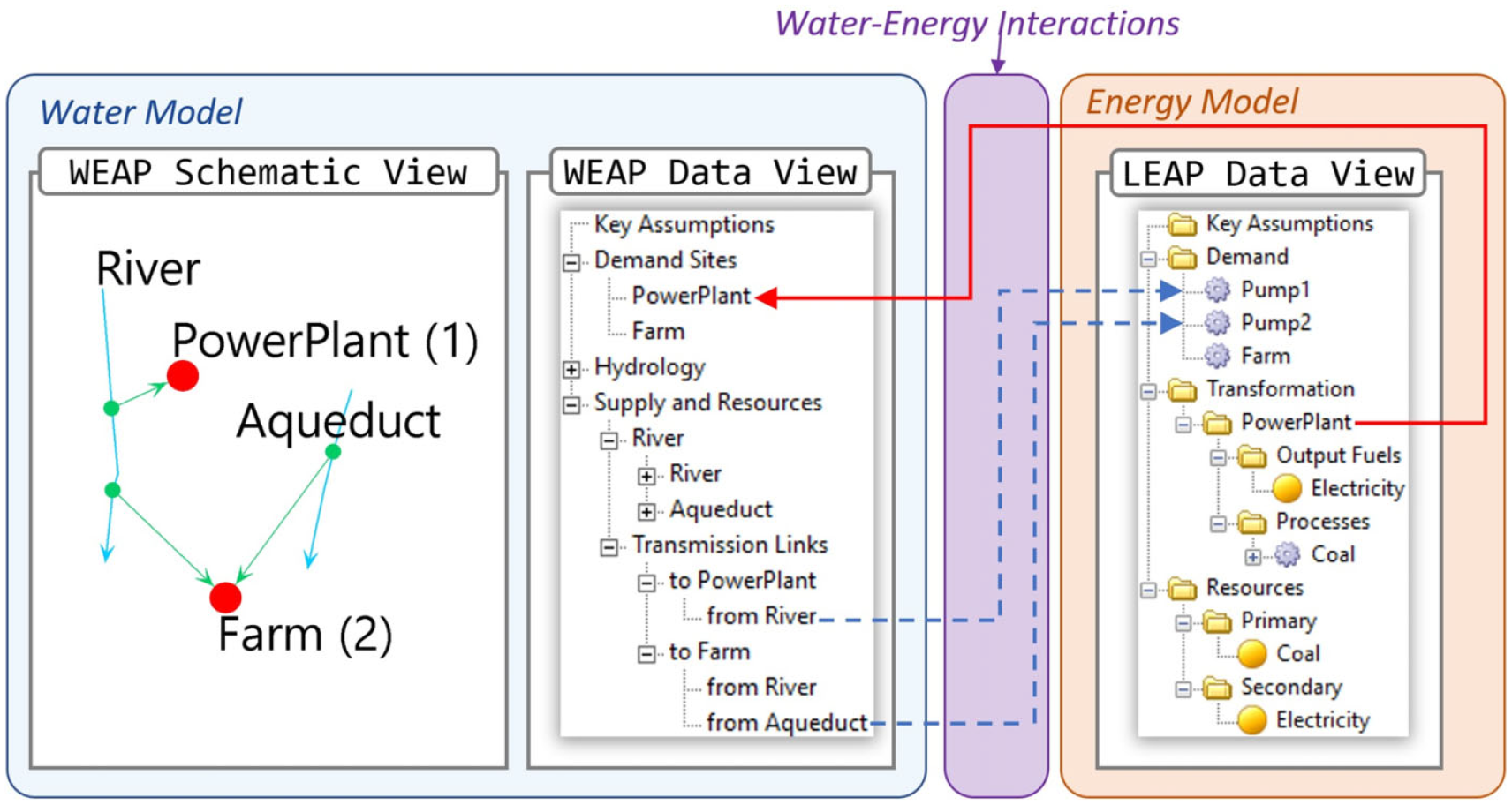
The exemplar water and energy models developed in WEAP and LEAP systems communicating with hidden read functions.
4. Approach
Using a formal modeling method to model and simulate the interactions between disparate models is advantageous. A component-based, hierarchical modeling approach that aligns with system thinking helps with the development, reuse, and maintainability of IMs. An IM framework is designed and developed based on the KIB approach and DEVS formalism (called the DEVS-IM framework). It has a unified concept for specifying general-purpose logical and persistent atomic and coupled DEVS models. The models are used to specify the hierarchical tree structure of the IM. The leaves of the tree structure are atomic DEVS models, and the rest are coupled DEVS models. The input and output ports can be defined for the models as the interface for message communication. The atomic and coupled models can be connected using coupling between their ports. The DEVS-IM framework supports storing models in the MongoDB database. Model creation, access, and manipulation are accessible via REST APIs. The DEVS-IM framework has some predefined elements (derived from the atomic and coupled DEVS models) to facilitate defining the IM for the users who are unacquainted with the DEVS formalism. Furthermore, the framework has a set of elements to define a generic ontology for the disparate external systems connected to the IM. Ontology has a critical role in simulation modeling, particularly in distributed simulations by addressing the challenges in simulation application integration, component-based simulation, and modeling at various abstraction levels. 69
4.1. DEVS-based IM
Figure 4 illustrates the conceptual architecture of the DEVS-IM framework. It is divided into three main sections; “Interaction Model,”“External System Schema,” and “External System.” The first two sections (the purple area) define the IM between disparate systems. The “Interaction Model” section is a coupled DEVS model to realize the KIB properties. The “External System Schema” section defines a tree structure as an interface for the external system. It implements the actual communication between the IM and the external systems. The “External System Schema” section is used to model the external system at different levels of abstraction. Any type of system/model can be considered as an external system; a stand-alone application, web services, database, library, and file system; for example, the developed water-interaction-energy model in this article (using the WEAP and LEAP systems) employs web services.
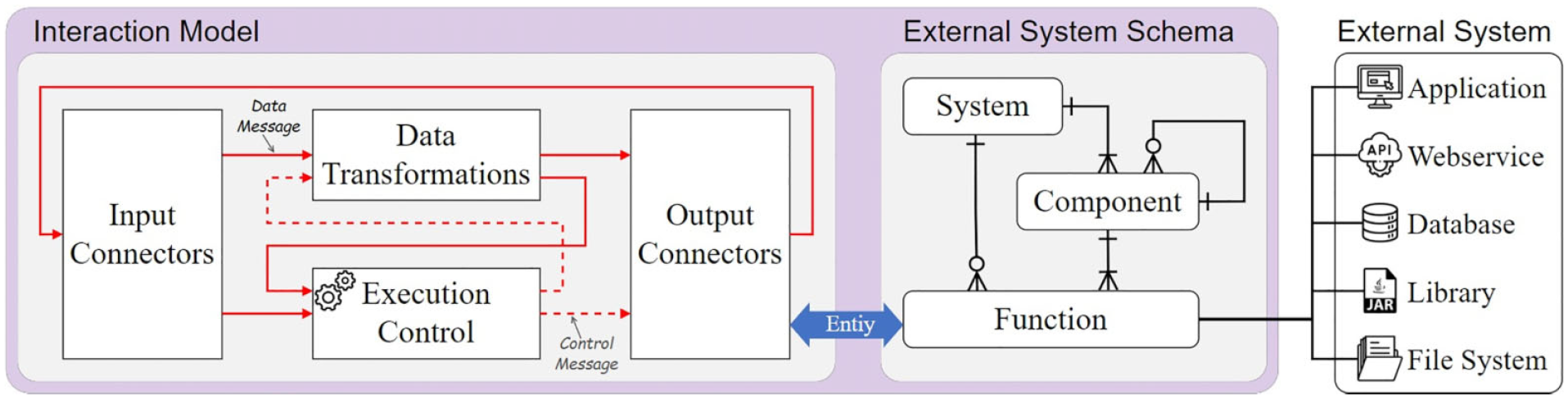
Conceptual architecture of the DEVS-based IM framework.
In Figure 4, the “Data Transformations” part contains all elements to process the input messages (e.g., aggregate, disaggregate, or convert the data) and then generate output messages. This part is the realization of the data transformation property of the KIB approach (the same functionality of the Transformation element in the Algorithmic-IM framework). The data carried in a message in the DEVS-IM framework can be as simple as a primitive data type value (e.g., integer or string) or as complex as a user-defined model. The “Execution Control” part in Figure 4 involves timing, synchronization, and concurrency properties of the KIB approach. Each disparate model executes in its framework and follows its execution protocol. As the coordinator, the DEVS-IM model has its execution protocol to coordinate and synchronize the executions among the DEVS-IM models and disparate external systems. Synchronization control is crucial to ensure message ordering and causality among the models. The “Execution Control” section can send control messages (dotted red arrows) to the data transformations or output connectors based on the received data messages (solid red arrows) from input connectors and data transformations. Given different DEVS-IM execution algorithms, the disparate models and the IM can be executed sequentially or in parallel. The Time property of the KIB in this research focuses on controlling the logical time of the DEVS-IM model and the external systems. It ensures that when a model receives a message from another model (probably with a model developed in a different formalism), the essential time associated with the message represents the same time in the model. It must be done at the modeling specification and simulation/execution levels.
The “Input Connectors,”“Data Transformations,” and “Execution Control” in Figure 4 are pure DEVS models. The “Output Connectors” communicate with the outside world via the “External System Schema.” A communication message between the “Interaction Model” section (specifically, the “Output Connectors” part) and the “External System Schema” section (specifically, the “Function” part) must be inherited from the Entity class (a base class in the DEVS-Suite simulator). The “Function” part is responsible for receiving/sending data from/to the external systems in any format or structure. Indeed, the results from the outside world (received in the “Function” part) must be converted to the Entity type before returning them to the “Output Connectors” part. During the simulation execution, the received data in the “Output Connectors” part (from the external systems) are sent to the “Input Connectors” (indicated by the solid red arrow from “Output Connectors” to the “Input Connectors” in Figure 4). In general, disparate systems present distinct specifications on the model structure. Therefore, the structural composition specification of the KIB is desired to handle the differences in the interface structures between the models in different systems.
4.1.1. IM specification
The DEVS-IM model can be defined using predefined IM, Input Connector, Output Connector, Process, Task, Port, and Coupling elements. It also supports defining an interface for external systems using predefined System, Component, and Function elements. Figure 5 illustrates the order of defining different elements of a DEVS-IM model. A Project element can contain multiple IMs between disparate systems. The purple solid line and yellow dotted line elements in Figure 5 are used to define the “IM Model” and “External System Schema” sections in Figure 4. The IM element defines the IM between the systems (the root element of an IM). It can contain four types of sub-elements/children; Input Connector, Output Connector, Process, and Task. The Input/Output Connector element defines an interface for the IM element to receive/send data from/to the external systems. The Task element defines a data transformation, and the Process element provides the hierarchy modeling. A Process element has a set of Process and Task elements as its sub-elements. The Port element (input and output) defines the communication part between Task, Process, and Connector elements. Finally, a Coupling element can be defined between two Port elements or between one Connector element and one Port element (the solid and dotted red connections in the “Interaction Model” section in Figure 4).
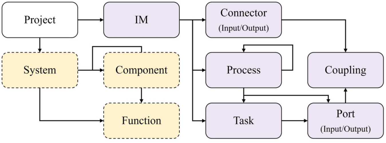
Abstract structure defining the elements and their relationships in the DEVS-IM framework.
In defining the “External System Schema,” the System element defines the root node of a tree (usually with the same name as the external system). Multiple Component and Function elements can be defined under the System element (see the Entity Relation diagram in the “External System Schema” section in Figure 4). Each Component element is a representation of a specific entity in the external system. It can contain multiple Component and Function elements to define the hierarchy structure of the schema for the external system. The Function element (which is always a leaf of the tree) handles a specific functionality of the representative entity in the external system. Each Function element has two responsibilities: (1) sending/receiving data to/from the external systems (e.g., calling APIs in the presented WEN Example) and (2) data type conversion between the acceptable type by the DEVS-IM simulator (i.e., Entity class) and an acceptable type/format by the external system (convert Message to JSON and vice versa).
Figure 6 illustrates the architecture of manipulating the model structure in the DEVS-IM framework. The DEVS-IM is supported by a RESTful framework to define the model’s structure and store them in the MongoDB database. Different elements can be created, read, updated, and deleted (CRUD operations) via the HTTP POST, GET, PUT, and DELETE methods. The “REST Request Handler” receives a request and routes it to a proper service. The body of the POST requests must have a specific structure (see Figure 7 in Fard and Sarjoughian). 11 A separate service for each DEVS-IM element is defined in the “Service Handler” section. At this step, the required verifications are checked on the incoming request (from the client), then the changes are applied to the database if all verifications are passed. A proper error message will be returned to “API Caller” if the request is not defined correctly or violates a rule. Otherwise, the database will be changed, and the retrieved data from the database (Domain models) are converted to the Data Transfer Object (DTO) model by the “Service Handler,” and then converted to the JSON object by the “REST Request Handler.” Eventually, the client receives a response in JSON format.
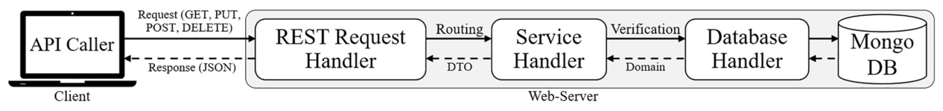
DEVS-IM framework architecture to define the model’s structure.
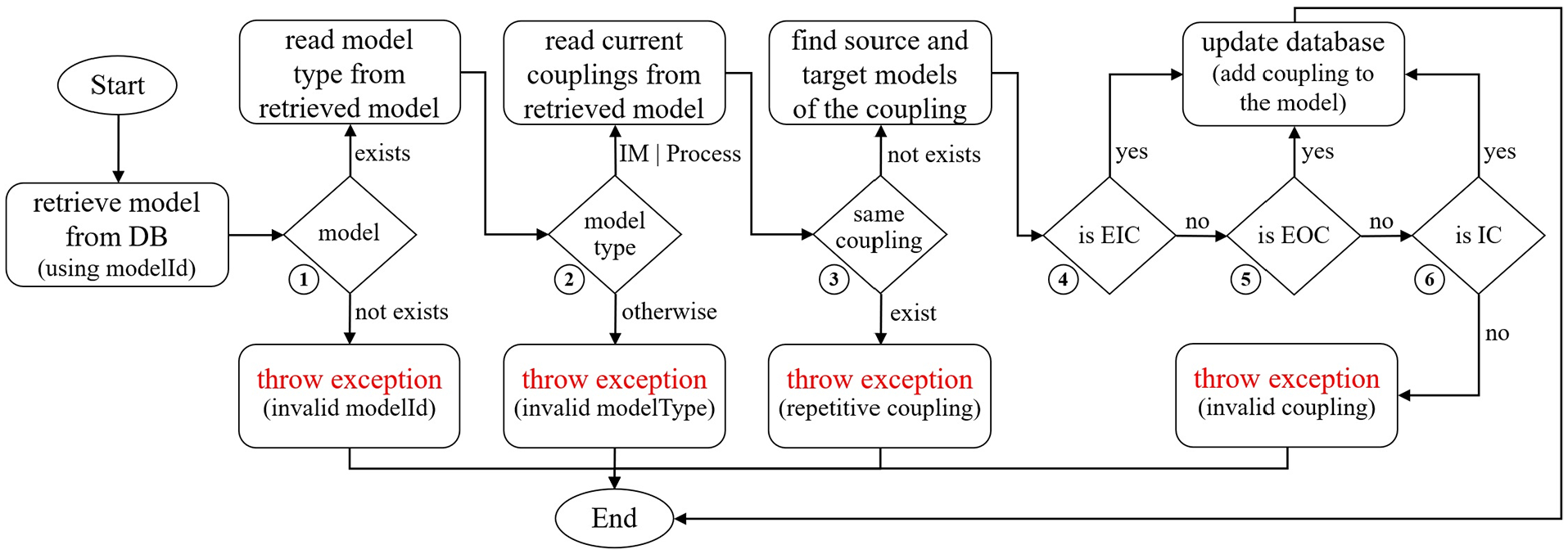
Structural consistency verification for inserting Coupling elements in DEVS-IM.
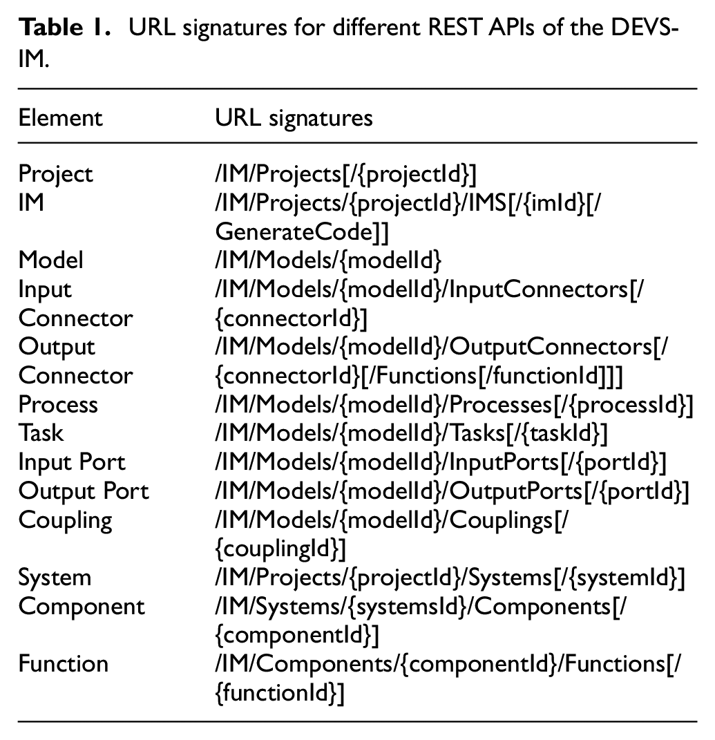
Table 1 presents the Uniform Resource Locator (URL) signatures for existing REST APIs of the DEVS-IM framework to define a model. In the signature of the URLs, constants are written in PascalCase style; parameters are written in camelCase style, and they must be inside the open and close pair curly brackets. The content inside each open and close pair of square brackets is optional to define different APIs for an element. Figure 7, in the work by Fard and Sarjoughian, 11 presents the REST APIs’ communication data schema (body of the requests). As an example of using APIs, calling the URL “/IM/Projects” via a POST method with “{“name”: “WEN”}” as the body of the request will create a new project and return the Id of the inserted data into the database if it passes the verification phase (i.e., if the project name has a correct pattern and it is not repetitive). As another example, calling the URL “/IM/Models/1” as a GET method will return a list of all sub-models and the couplings of the sub-model with modelId equal to one (given having a valid Id).
URL signatures for different REST APIs of the DEVS-IM.
4.1.2. Model verification
The applied verification on each received request guarantees that the stored model in the database is always a valid model from the structure point of view. Different verifications are defined for CRUD operations on each element. A proper error message is returned in JSON format if the request breaks any verification rule of defining the structure of the model. Otherwise, a JSON object with proper attributes to show successful operation will return as the response. For example, the framework prevents duplicate names for a type of element (e.g., Process, Task, or Input/Output Port) in the same scope (the same hierarchy level).
Figure 7 illustrates a structural consistency for inserting a Coupling element in the DEVS-IM framework. Suppose an API caller requests the URL “/IM/Models/1/Couplings” via a POST method with “{“sourcePortId”: 1, “targetPortId”: 2}” as the body of the request. After routing to a proper service (see Figure 6), the verification starts by checking the modelId. It retrieves a model with id that equals one (based on the received id in the URL). The first checking will be passed if the model exists. Otherwise, an exception with the message “invalid modelId” returns to the caller. In the second step, the type of the model must be checked. The IM and Process elements (coupled DEVS models) can have coupling. So, an exception with the message “invalid modelType” returns to the caller if the type is not valid. In the third step, the model is checked for trying to insert repetitive coupling. So, an exception with the message “repetitive coupling” returns if the coupling already exists in the current model. The next step is finding the source and target models of the coupling (using the sourcePortId and targetPortId in the body of the request) to verify the coupling based on the DEVS specification. A coupling is valid if it is an External Input Coupling (EIC): coupling from the input port of the current model to the input port of a sub-model, External Output Coupling (EOC): coupling from the output port of a sub-model to the output port of the current model, or Internal Coupling (IC): coupling from the output port of a sub-model to the input port of another sub-model (see section 2.3). An exception with the message “invalid coupling” returns if none of the conditions are satisfied (specified by numbers 4–6 in Figure 7). The model in the database will be updated (add the coupling to the model) if all checking steps are passed.
Furthermore, a tree structure must be defined for the “Interaction Model” and the “External System Schema” sections in Figure 4. So, the framework always checks not to have a loop in defining a model. In other words, a model cannot be a self-child. Otherwise, it makes an infinite loop in the defined model. Also, the “name” attribute of all elements (except the Port element) must follow the pattern “[a-zA-Z][a-zA-Z_$ 0-9]” because the name of these elements will be used in the code generation phase to define the name of the generated packages and files (the code generation is explained in the next section).
4.2. Exemplar water-energy nexus model: Part B - DEVS
The DEVS-IM model for the exemplar WEN system (see Figures 2 and 3) is defined using 88 APIs with the POST method from Table 1 (1 Project, 2 System, 10 Component, 8 Function, 1 IM, 7 Input Connector, 8 Call Output Connector, 2 Process, 5 Task, 22 Port, and 22 Coupling elements). Figure 8 presents a schematic view (drawn manually) of the defined DEVS-IM model. Two interfaces are defined for the water and energy external systems, and they are presented in a tree structure. The water interface has a run() function to execute the WEAP model and two sub-components for the demands and supplies. The required functions to get/set the values from/to the external systems are defined under the correspondence components (i.e., the setFlow() function under the “PowerPlant” component and the getFlow() function under “Canal1” and “Canal2” components). The same approach is applied for the energy interface to define its demands and supplies. The tree structure of an interface is not required to be the same as the structure of the external correspondence system. Different interfaces at different levels of abstraction can be defined for an external system (based on the modeler’s approach). Compare the defined interfaces in Figure 8 with the defined model in the WEAP and LEAP systems in Figure 3. For example, “Canal1” element in Figure 8 (under the supplies of the water interface) is a reference to the Transmission Link entity from the “River” to the “PowerPlant” entities in the WEAP model (see Figure 3). It is simplified to one element in the interface for the external system in Figure 8 (instead of defining the whole hierarchy presented in the WEAP model) and hides some details which are not important or not used in the IM.
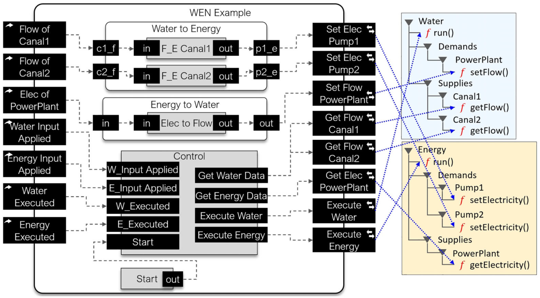
A schematic diagram of the defined DEVS-IM model for the exemplar WEN model.
The IM is defined using seven Input Connector, eight Call Output Connector, two Process, and five Task elements (the left side in Figure 8). Each output connector connects to a specific function of the external system schemas. There is a coupling between the output connectors and input connectors, but they are not presented in Figure 8 for simplification and focus on the connection between the IM and external system schemas. Indeed, all output connectors are coupled with a specific input connector (e.g., the “Get Flow Canal1” output connector is coupled with the “Flow of Canal1” input connector) to send the results. The “Control” element controls the synchronization between different parts of the IM and the external systems. It also manages the concurrency/execution of the three main systems (i.e., water, energy, and IM). The Process elements contain the Task elements to transform the Flow/Electricity values from the water/energy model to the Electricity/Flow values for the energy/water model (i.e., implementing the Formulas (1)–(4)). The execution mechanism is explained in the next sections.
As mentioned before, the DEVS-Suite simulator is used in this research to simulate the IM. The structure of models is defined using the DEVS-IM REST APIs and the data are stored in the MongoDB database. The required classes (in Java programming language) for the DEVS-Suite simulator must be generated to add the behavior for the atomic models (Task and Function elements) by the modeler.
4.3. DEVS-Suite code generation
The code generator of the DEVS-IM framework supports translating the models that are stored in the database to source code for target simulation and markup languages. Figure 9 presents the code generation schema from the DEVS-IM model to generate meaningful java classes, as the skeleton of a complete project in the DEVS-Suite simulator. The stored model in the database (defined via the REST APIs) is fetched and passed to the “Template Files” (using the “Template Models”) to generate multiple packages and files. A set of “stg” files (String Template Group) is used as the template to define the skeleton of the final generated classes for different types of models.
70
The “Template Models” contains a set of DTO classes to transfer data from the database to the “Template Files” (see Appendix 1). A package with the same name (as the project name) will be generated and contains all files related to the project. For each project, the code generator generates one package for each IM model and one package for each system (
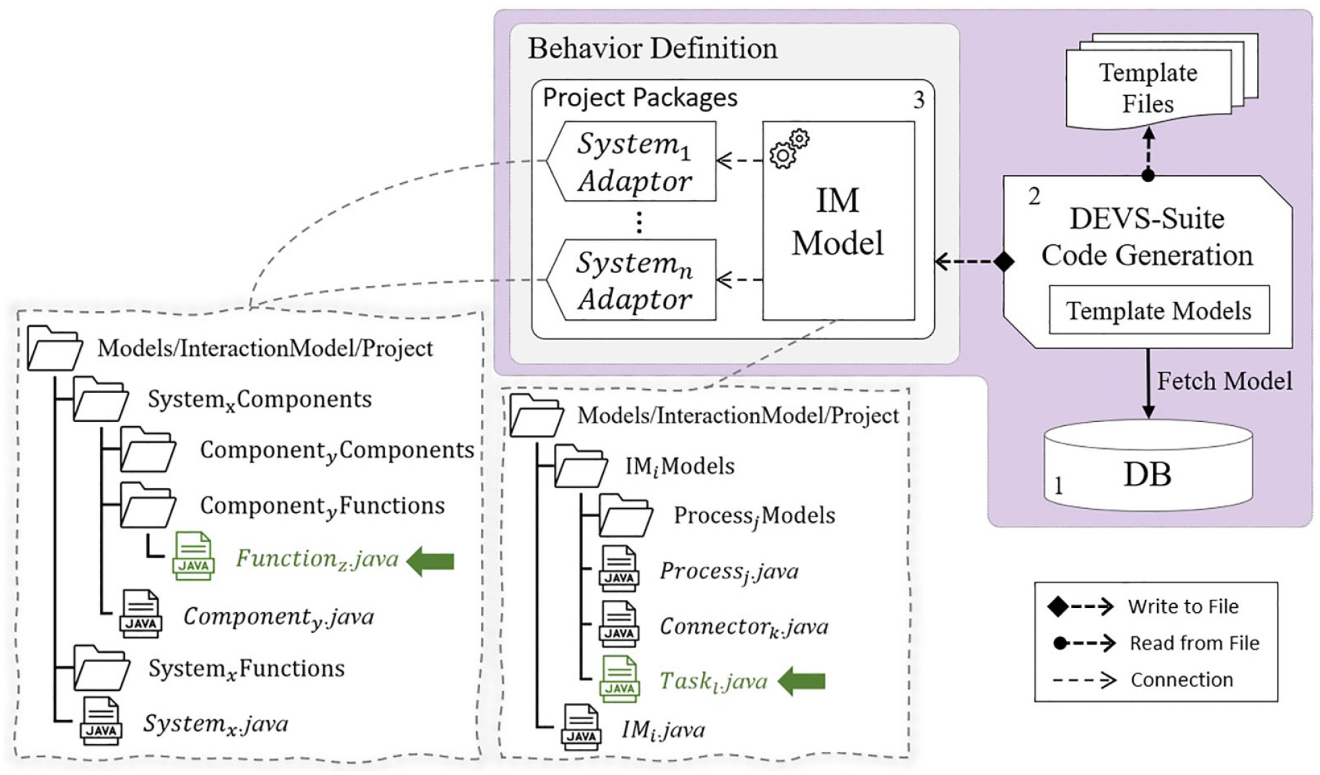
The code generation schema from the DEVS-IM model to the DEVS-Suite simulator.
From the DEVS specification point of view, the IM and Process entities are coupled models (but the IM does not have any input or output ports), and the Connector and Task elements are atomic models. The coupled models are presented using a java file to define the structure of the model and a package containing the sub-models. For example, in Figure 9, the “
To define a tree structure as an interface for the external system, the System/Component elements are presented using a java file to define the system/component and two packages for its sub-components and functions. For example, in Figure 9, the “
4.4. Exemplar water-energy model: Part C - DEVS-Suite
After using the Code Generation module of the DEVS-IM framework for the defined model in the previous step, the SimView window of the DEVS-Suite simulator and the generated packages (the focus of the Energy External System interface) for the exemplar WEN model are presented in Figure 10 (compare it with Figures 8 and 9). This is similar to DEVS-IM developed for the Phoenix Active Management Area (Phoenix AMA). 71 The Process elements are converted to the coupled DEVS models. The Task and Connector (input and output) elements are converted to the atomic DEVS models. The purple atomic models are used to control the execution (concurrency and synchronization), and the blue and yellow atomic models are connected to the water and energy models, respectively. Each connector has one input port (named “in”) and one output port (named “out”), which are added automatically during the model definition phase. The couplings between the output and input connectors are presented in this view (i.e., the coupling from the “out” output port of an output connector to the “in” input port of an input connector).
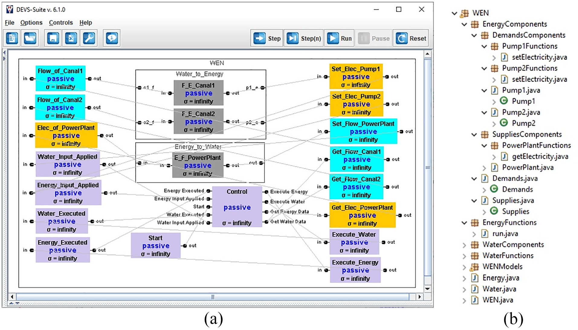
Automatically generated code for the exemplar WEN model. (a) The DEVS-Suite SimView. (b) Generated packages focus on the energy external system interface.
The “Interaction Model” and “External System Schema” sections of Figure 4 have been explained and the code generation module generates the required classes and packages related to these sections. Now, the communication between the “Function” part and the “External Systems” section in Figure 4 needs to be defined via coding. There exist a wide variety of tools for modeling and simulating the external systems (i.e., the water and energy systems). Also, various approaches have been proposed to transform legacy software systems into integrable with other software systems. 72 One of these approaches is “wrapping,” where any proprietary legacy software system with input/output API (e.g., WEAP and LEAP systems) can be encapsulated inside other software systems.73,74 Indeed, individual functions in the legacy software are wrapped into web services. This research follows the rationale and the general approach of transforming a legacy system into flexible service-oriented software frameworks in addition to component-based modeling and simulation.
The WEAP–LEAP system is appealing to domain experts from the standpoint of ease of use for rapid model development. In our previous publication, 9 the WEAP entities, input and output variables, and their data are represented using the Ecore meta-modeling approach, where each proxy model component corresponds to a WEAP entity. The Ecore presents a well-defined componentized specification for the WEAP legacy modeling and simulation system. These components are used in a flexible service-oriented framework. The outcome is the componentized WEAP RESTful framework. The framework helps to consider a set of component models instead of thinking about a group of shared variables (belonging to different entities) that are used in mass balance equations. Also, the REST APIs ease the use of the WEAP system in modern computing platforms, including its integration with other tools to model and simulate more complex systems, such as the WEN system. Every model entity developed in the WEAP system is automatically extracted and included as a componentized model in the componentized WEAP RESTful framework. In the following section, the componentized WEAP RESTful framework is presented from the communication perspective. The same approach is applied to the LEAP system.
4.5. Legacy tool componentization
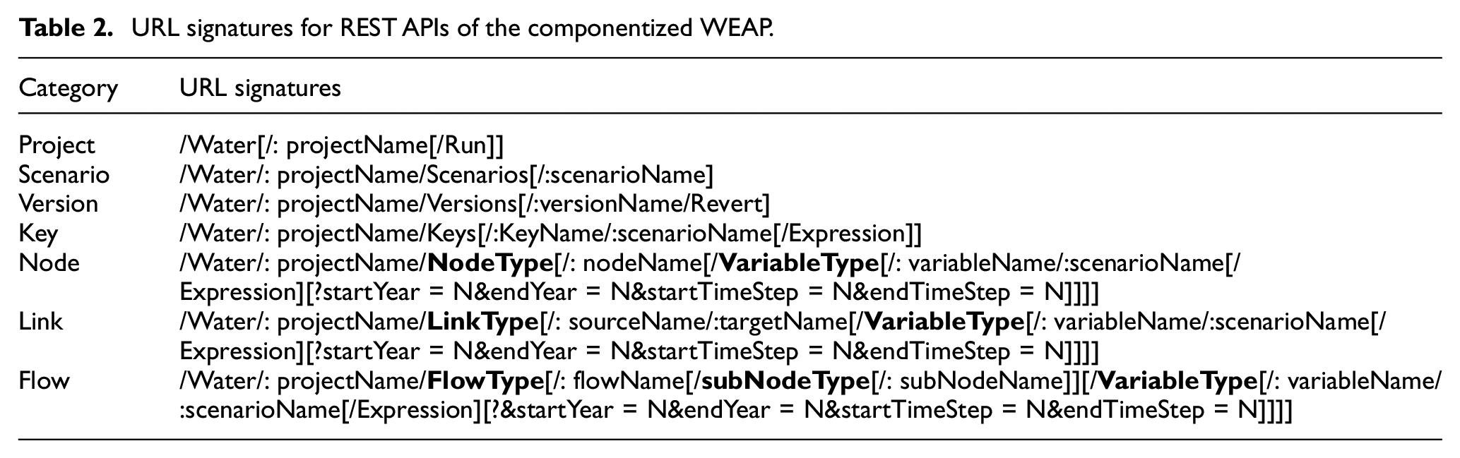
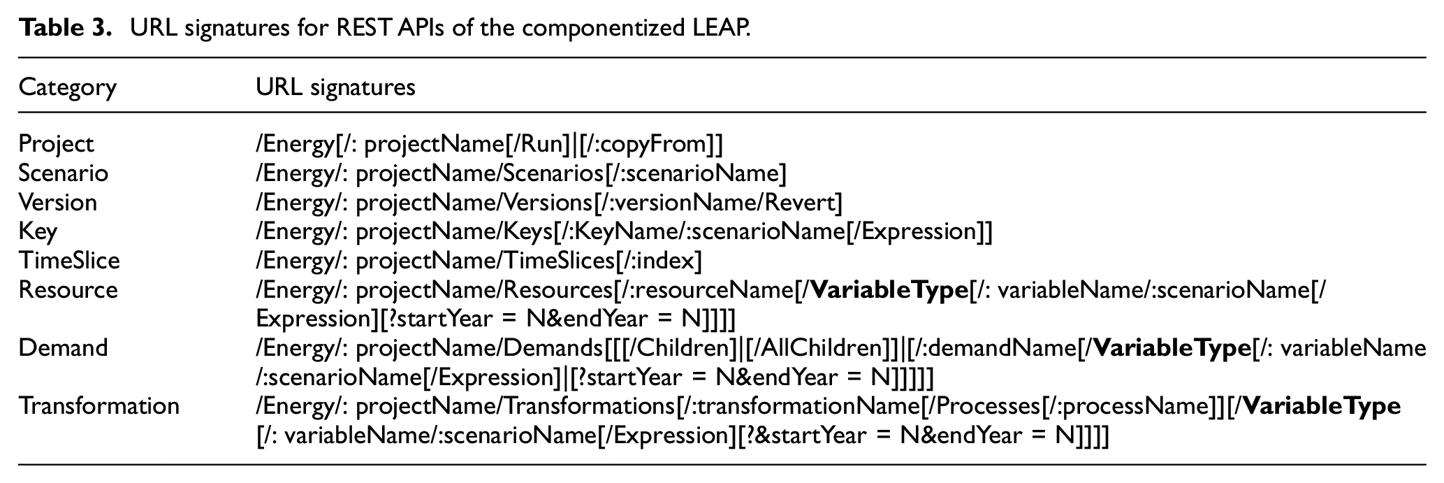
The componentization of the WEAP and LEAP systems supports a higher degree of control for manipulating and simulating the water and energy entity models. 9 The approach can help simplify the design of simulation experiments and optimization studies that can be difficult using the scripting languages supported in the WEAP and LEAP systems. The RESTful framework with the WEAP–LEAP componentization can lend itself to better support the development of customized tools. The API signatures of the componentized WEAP (in seven categories) and LEAP (in eight categories) RESTful frameworks are presented in Tables 2 and 3 in Appendix 2.
URL signatures for REST APIs of the componentized WEAP.
URL signatures for REST APIs of the componentized LEAP.
The componentized WEAP and LEAP frameworks represent the defined model in the WEAP and LEAP systems in a well-structured format. Figure 11 illustrates the data retrieving in the componentized WEAP RESTful framework. The process steps for a request are shown by the numbers 1–5 in the diagram. The process starts with receiving a request from the “API Gateway.” Based on received parameters (i.e., Entity Type, Entity Name, and so on), a proper method from the “Componentization” part is called to fetch data from a specific WEAP entity. Each entity has a list of variables (e.g.,
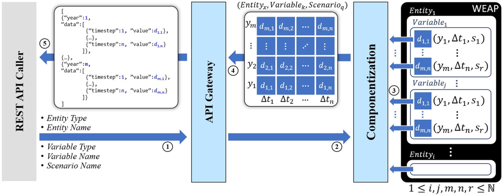
Data retrieval in the componentized WEAP RESTful framework.
There are two approaches for the componentization process; Pre-Componentization to componentize to entire water model before receiving any request, and Runtime-Componentization to componentize the required parts of a model based on the received requests at run-time. The first approach needs considerable time to componentize the whole model, whereas a small part of the model usually interacts with other systems. Furthermore, sometimes the API needs a portion of the values related to a variable (e.g., the first year of values). So, in this research, the componentized WEAP is developed based on the Runtime-Componentization approach. The componentized WEAP can filter the interval of the data (from
Compared with the scripting language supported in the WEAP tool, the performance evaluation for the componentized WEAP shows that the impact of componentizing the WEAP model on total time for simulation studies is negligible (around 4%). However, this evaluation for the componentized LEAP is varied and API-dependent because the WEAP system has scripting methods to get the data in the fine-grain time resolution (e.g., daily, weekly, or monthly). 7 However, the scripting language supported in the LEAP system returns data in yearly time resolution (even though the data are defined in a finer time resolution). To overcome this limitation in the componentized LEAP framework, the data of a variable are first saved in the flat files. Then, the required data are extracted from them. So, the performance of APIs related to the fine-grain time resolution data is lower because of using many flat files.
4.6. Exemplar water-energy model: Part D - JSON syntax
Considering the defined water and energy models in the WEAP and LEAP tools in Figure 3, Figure 12 presents the JSON results of calling some APIs to get data for the defined entities, variables, and simulation values. Given the execution of the WEAP–LEAP tool and the componentized WEAP–LEAP framework, Figure 12(a) shows the result of calling “/Energy/WENExample/Demands” via the GET HTTP method. The result contains a list of demands defined in the “WENExample” project (see Figure 3). Each demand has name, id, parentId, and order properties. Figure 12(b) shows the result of calling “/Water/WENExample/Demands/PowerPlant/Outputs” via the GET HTTP method. The result contains a list of all output variables of the “PowerPlant” demand site in the “WENExample” project. Each variable has name, unit, min, max, isReadOnly, and isUserDefined properties. Figure 12(c) presents the retrieved dummy data from the water model for “Water Demand” variable of the “PowerPlant” demand site for “CurrentAccount” scenario and data are filtered for 2010 values (by calling URL = “/Water/WENExample/DemandSites/PowerPlant/Outputs/Water Demand/Current Account?startYear = 2010, endYear = 2010”). The data section has four values for different timesteps (i.e., seasons). The similar API from the LEAP system, Figure 12(d), returns one value per year because it is assumed to have yearly time granularity for the energy system in the WEN example (see Figure 3).
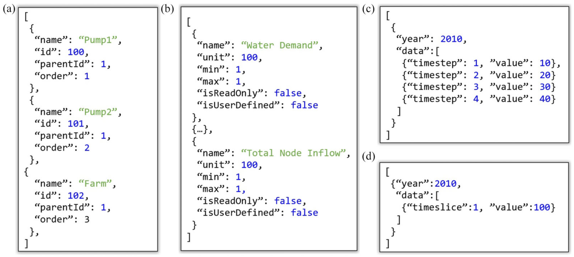
(a) JSON result of calling URL: “/Energy/WENExample/Demands,” (b) JSON result of calling URL: “/Water/WENExample/DemandSites/PowerPlant/Outputs,” (c) JSON result of calling URL: “/Water/WENExample/DemandSites/PowerPlant/Outputs/Water Demand/CurrentAccount?startYear =2010,endYear = 2010,” and (d) JSON result of calling URL: “/Energy/WENExample/Demands/Pump1/Inputs/EnergyIntensity/CurrentAccount?startYear = 2010,endYear = 2010.”
4.7. DEVS-IM behavior definition
Calling the componentized WEAP REST APIs must be defined in the Function elements of the IM (see Figure 4). A base package named “core” is implemented in the DEVS-Suite simulator, which contains the super abstract classes for all element types of the DEVS-IM framework (see Figures 2 and 3 in Fard and Sarjoughian)bib11. 11 A partial behavior for the Task abstract class is defined in the core package. The inherited class from the Task class must complete the behavior. The Input/Output Connector abstract classes in the core package are inherited from the Task class, and their default behavior is defined, as well. The design of the classes in the core package has the flexibility to define a new type of element by the modeler (e.g., a new connector element).
4.7.1. DEVS-Suite core models
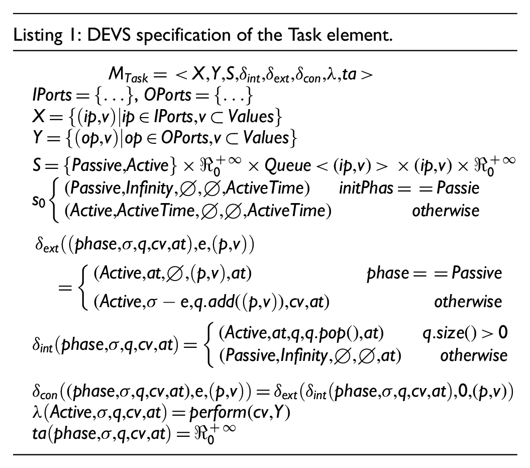
The DEVS specification of the Task element is defined in Listing 1. The modeler must define the input and output port names and values. The state variable is defined using the phase, sigma, queue, current message, and active time. The “Active” and “Passive“ are two valid values for the phase attribute. The queue stores the input messages received on the input ports if the model is processing another input. The current message indicates the message that the model is processing. The active time indicates the required time to process input (amount of time for being in the “Active” phase). The default value for the active time is zero. However, it is an input parameter of the Task class in the DEVS-Suite simulator, so it can be set to different values for different task instances. The external transition function sets the active time and input message to the sigma and current message state variables if a model is in “Passive” phase. Otherwise, the input message is added to the queue variable, and the sigma is updated. The internal transition function starts processing the next input message if the queue is not empty. Otherwise (the queue is empty), the phase is changed to “Passive.” The actual data transformation must be defined in the perform method. The output function is responsible for calling the perform method and passing the required parameters to it (the current message and the output set). The specifications for the remaining functions are straightforward. By having these specifications for the Task element, a modeler who is not an expert in the DEVS formalism can define the behavior of the transformations (in the perform method) without going deep into different functions of the atomic DEVS model.
One input connector type is defined in the DEVS-IM framework (i.e., the TransientInput connector element). 11 The DEVS formal specification is presented in Listing 2. All predefined input/output connectors in the DEVS-IM framework have one input port (named “in”) and one output port (named “out”). The behavior is defined as transiently transferring any input message on the “in” input port to the “out” output port of the model (active time is zero). The state variable is defined using the phase, sigma, and the received Values on the message.

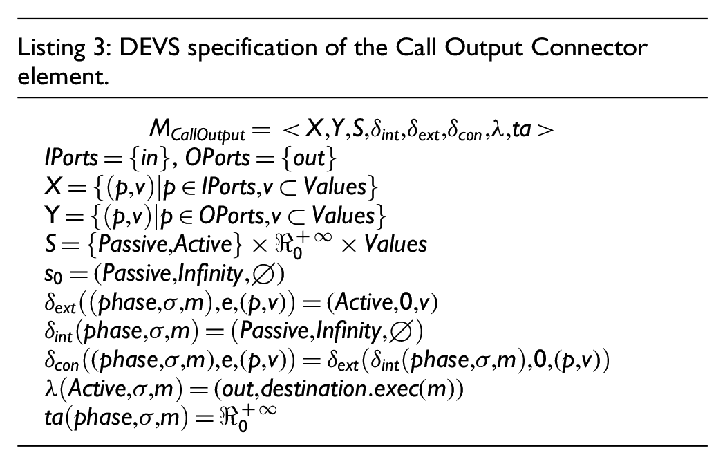
Three types of output connector elements are defined in the DEVS-IM framework; CallOutput, TransientOutput, and QueueOutput connectors (please see section 4.2 in Fard and Sarjoughian 11 for more details). The CallOutput connector is connected to one Function element. The defined behavior for this model is sending the received message on the “in” input port to the connected Function element. Then, execute the exec method of the Function element and put the result of the execution to the “out” output port of the connector (which will be sent to an input connector). The DEVS formal specification of the CallOutput connector is presented in Listing 3. Like the TransientInput connector, the state variable is defined using the phase, sigma, and the received Values on the message. The destination in the output function refers to the connected Function element to the model. The TransientOutput connector is connected to a set of Function elements. The defined behavior for this model is sending the message received on the “in” input port to all connected Function elements and executing their exec method. The QueueOutput connector queues the message received on the “in” input port to be read in the future.
4.7.2. Execution control
Different modeling formalisms in a heterogeneous modeling environment provide their approaches for modeling behavioral specification and execution protocol. Consequently, the simulation time management and synchronization mechanisms of different modeling formalisms can be so distinct that the dynamic interaction between the disparate models may result in unexpected errors without a well-defined composite behavioral specification or a well-designed coordination execution protocol. The DEVS-IM framework is grounded in system theory and component-based modeling. The model specification and execution protocol are separated in the DEVS-IM framework (based on using DEVS formalism). It supports the model reusability, flexibility, and maintainability traits essential for developing realistic simulations (such as coupled energy and water systems). The Parallel DEVS supports concurrent execution of the DEVS models. Therefore, the DEVS-IM model may send messages to disparate external systems simultaneously. Also, the DEVS-IM model must be capable of dealing with concurrent messages from external systems.
The DEVS-IM simulator framework supports synchronous communications/executions. Based on the defined execution control in the IM (see section 4.1), multiple requests from the external system/s (e.g., send data, receive data, run the external simulation, and so on) can be invoked sequentially or in parallel. The time inside the IM would not be elapsed while it is waiting for the result/s from the external system/s. In the sequential execution control, the IM requests a specific action from an external system and waits for its result. Then, another request from the same or another external system can be invoked. In the parallel execution control, the IM requests multiple external systems simultaneously and waits for all results. A hybrid execution can be defined in the IM, meaning that some intervals follow the sequential execution, and others follow the parallel execution (based on the defined execution control for the model). Even though asynchronous execution can be supported by the programming language of the DEVS-Suite simulator (the Java programming language), the simulator cannot guarantee a robust execution for the asynchronous behavior.
4.8. Exemplar water-energy nexus model: Part E - formal specification
Listing 4 shows a pseudo-code to control the execution for the exemplar WEN model. It has five input ports and four output ports. Lines 1–5 define the local variables with their initial values. Lines 6–8 must be implemented by all Task elements to define the behavior of the model. In this example, two sub-procedures are called to read the messages on the input ports and produce some messages on the output ports. The CheckInputMessages procedure (Lines 9–20 in Listing 4) sets the local variables based on the read messages on the input ports. For example, the control starts executing by receiving a message on “Start” input port; or it increases the EnergyInputApplied variable for one unit by receiving a message on the port “Energy Input Applied”; and so on.
The FillOutputMessages procedure can have a sequential execution for the external systems (Lines 21–36 in Listing 4). In the sequential execution, the water and energy models run alternatively (see toggling the isWaterExecuted and isEnergyExecuted local variables). The WaterInputApplied and EnergyInputApplied variables check that all output values are applied to the external systems (i.e., set_Elec_Pump1 and set_Elec_Pump2 for the energy system, and set_Flow_PowerPlant for the water system). Lines 36–49 in Listing 4 present the parallel execution of the water and energy systems. These are two samples of the sequential and parallel executions applied by the Control model. Any other execution can be implemented by the user (based on the input and output messages and the coupling from Control to the other models). Different execution controls for the same systems can produce different results.
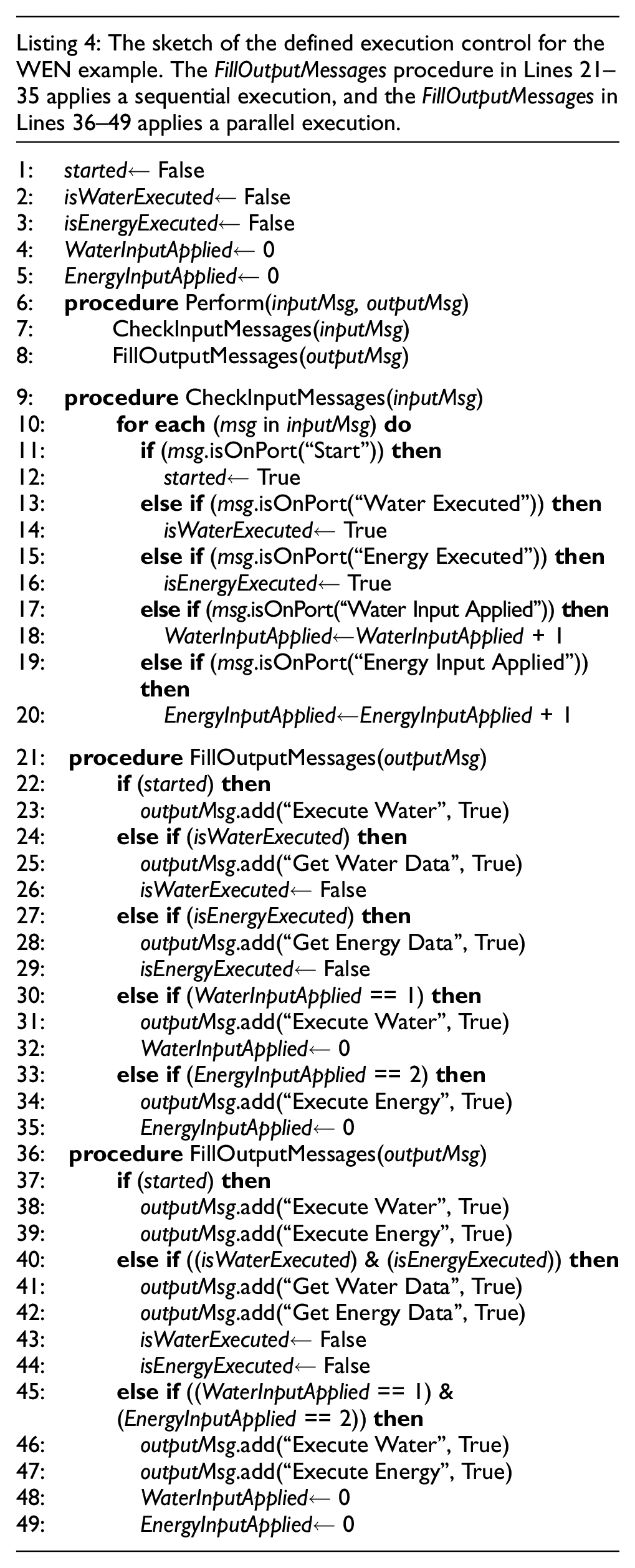
Figure 13 illustrates a Unified Modeling Language (UML) activity diagram for round-based execution of the exemplar WEN model defined in DEVS-IM model. The previous section was focused on the control mechanism in the IM. The communication between Interaction Model, External System Schemas, and the External Systems is described here. The IM can call functions from the Water and Energy Schemas (see Figure 4 for the Function component concept and see Figure 8 for the schemas of the exemplar WEN model). The functions of the water and energy schemas are responsible for calling proper APIs from componentized WEAP and LEAP services. The External System Schema not only presents an interface for the External System but also converts all incoming messages from the outside world (JSON messages coming from componentized WEAP and LEAP) to Entity and sends them to the IM.
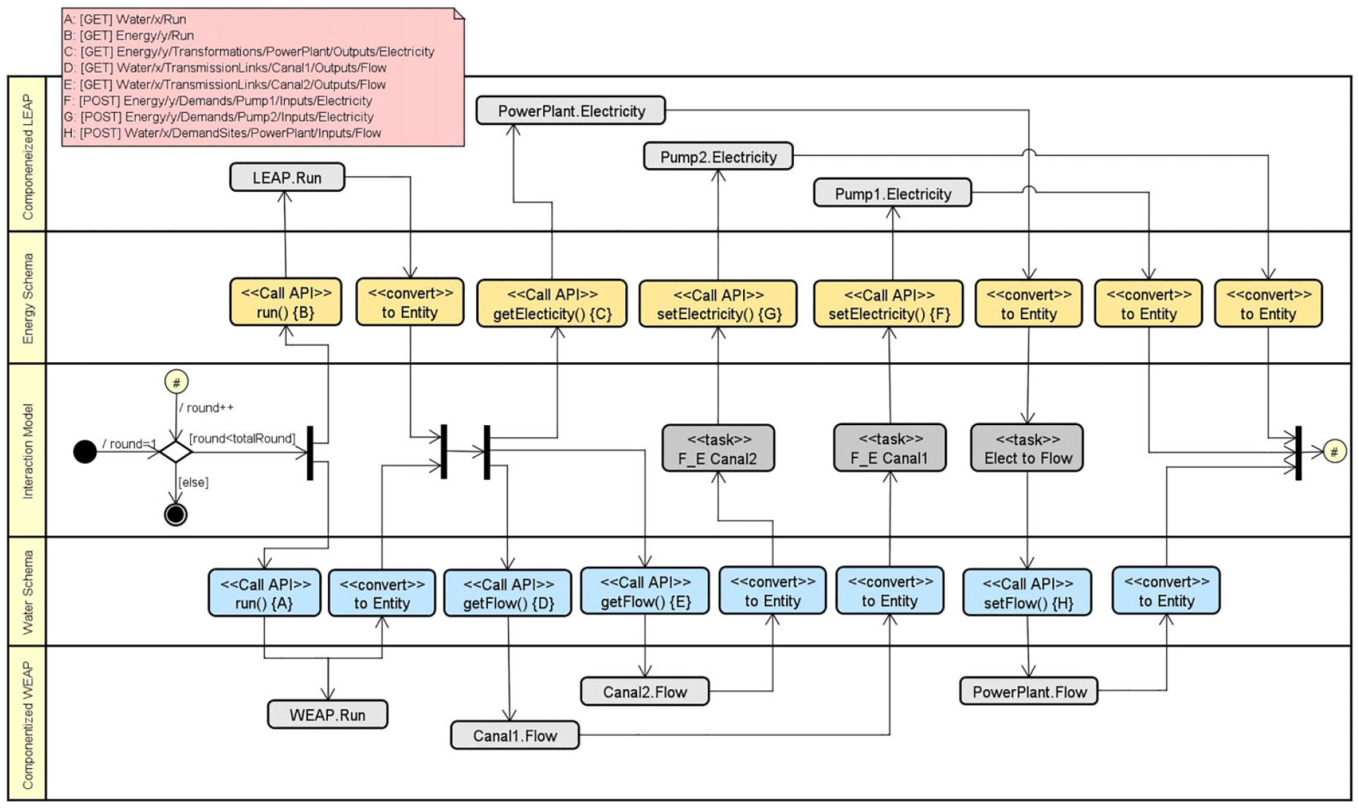
UML Activity diagram for the round execution of the exemplar WEN model.
Regarding a round-based execution for the exemplar WEN model, the totalRound parameter defines the total number of rounds to execute the model. The simulation execution stops when the value of the current round is equal to the totalRound. Otherwise, a round execution will be started which includes three steps. First, the water and energy models will be executed simultaneously. Second, the Flow of the of the Canal1 and Canal2 components and the Electricity of the PowerPlant component are fetched from the water and energy models. Third, the transformation from Flow to Electricity, and vice versa, will be triggered and the results will be sent to the water and energy models (i.e., componentized WEAP and LEAP).
Figure 14 illustrates the sequence diagram of executing the water system (WEN project of the WEAP tool) in the defined DEVS-IM model. Compare the models (in Energy Schema and Water Schema partitions) in the sequence diagram with the models in Figure 10. In Step 1, a message is sent from cont object (an instance of the Control atomic model) to the ew object (an instance of the Execute_Water output connector) via their coupling. In Step 2, the ew object calls the exec() method of the runWEAP object (an instance of the run function). In Step 3, an API from the componentized WEAP framework is called to run the “WEN” project. In Step 4, the componentized WEAP framework executes the project and returns the True value in JSON format. Then, the runWEAP object puts the received JSON result in a message of type Entity (see section 4.1) and returns the message to the ew object. All communications from Step 2 up to this point were a synchronous process. In Step 5, the ew object sends the received message to the we object (an instance of the Water_Executed input connector) via their coupling. Consequently, the received message is sent to the cont object in Step 6. Finally, the isWaterExecuted variable of the cont object is set to True (see (a)). The same steps apply to read/write values from/to a specific variable of an entity in the WEAP and/or LEAP models.
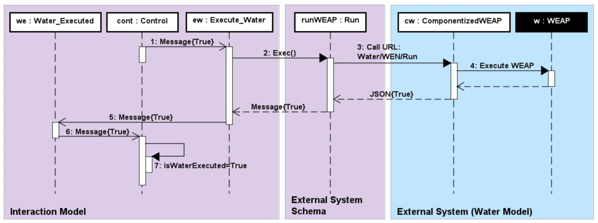
Sequence diagram snippet specifying the order of message calls and signals between the DEVS-IM and the WEAP system.
5. Discussion
The role of KIB-based model composition for modeling hybrid water–energy systems sheds light on the difficulty and challenges of combining models. Considering the use of WEAP–LEAP internal linkage, it is impractical to independently manage the water and energy models’ distinct time resolutions without defining their interactions as a separate model. Aside from time, the remaining data mapping, control, and concurrency aspects of the KIB are also not supported or challenging to achieve. The approach of WEAP–LEAP internal linkage to combine water and energy models faces complications without interaction modeling:
First, the same time granularity (e.g., daily or yearly) is assumed; otherwise, the time resolution in one model must be adjusted to that of another model. 10 Using the DEVS-IM allows the time granularities in the water and energy models to be completely independent of one another. Time granularity differences are entirely accounted for in the DEVS-IM.
Second, the WEAP and LEAP system and their internal linkage can only be executed on the same computer. 75 This requirement is unnecessary for the KIB-based RESTful composability framework since its underlying SOA allows the water, energy, and interactions models to be simulated on different computers.
Third, the water and energy model interaction can be sequential and manually simulated. 75 The execution control in the DEVS-IM framework allows synchronous (parallel) execution. 11 This may lead to efficient executions of the whole water, energy, and IMs.
Fourth, to use the WEAP–LEAP internal linkage, modelers should know the internal details of water and energy models to model their relationship. 75 In comparison, the DEVS-IM modeling benefits from the modular, hierarchical capabilities of the DEVS modeling and simulation.
Comparing the Algorithmic-IM framework and the DEVS-IM framework, the former has four significant restrictions:
First, one level of the hierarchy is allowed to define the IM structure in the Algorithmic-IM, 10 whereas the DEVS-IM supports arbitrary levels of hierarchy.
Second, the model structure and execution protocol are inseparable in the Algorithmic-IM. The DEVS-IM’s realization is the DEVS-Suite simulator which allows any IM to be simulated using the same execution protocol.
Third, the execution order of data transformations from water to energy and vice versa is fixed (six sequential steps) in the Algorithmic-IM, whereas the DEVS-IM framework allows arbitrary parallel ordering of data transformations.
Fourth, the IM must be defined using Java language and stored in flat files in the Algorithmic-IM. The DEVS-IM framework facilitates the use of the DEVS-Suite simulator and storing IMs with their combined water–energy projects.
The applicability of the KIB-based model composability framework detailed in section 4 is demonstrated for the Phoenix AMA. 75 The DEVS-IM has 6 water supplies (2 River, 2 Groundwater, and 2 Wastewater Treatment Plant entities) and 18 demands (12 Catchment for irrigation and 6 Demand Site entities for the rest of the demands) using 61 connections between them (56 Transmission Link and 5 Return Flow entities) to form the water system. 76 The defined energy model has 9 Resource, 1 Transformation with 27 processes, and 93 Demand entities. 77 The water and energy models interact with one another in 183 ways (172 from the water model to the energy model and 9 from the energy model to the water mode). The interactions for the Phoenix AMA are defined as a three-level hierarchical model with 307 atomic models and coupled models, 942 ports, and 740 couplings. 75 This IM contributes to the transparency of building high-fidelity simulations of water–energy systems compared to WEAP–LEAP internal linkage and other prototypical ways the models can be combined. The computational cost of simulating the Phoenix AMA using the DEVS-IM is higher (~2.5 times) than using WEAP–LEAP internal linkage and similar compared to the Algorithmic-IM using the same computing platform. 11 However, the KIB-based interaction modeling serves essential benefits, such as the kind of model that can be systematically and at scale developed, simulated, verified, and validated that can be difficult at high cost or otherwise impractical.
6. Conclusion
Model composition for independently developed models should reduce or remove the complications that arise because of data sharing, input/output communication, and mapping models from one abstraction level to another. While some homogeneous modeling formalisms offer concise syntax and semantics for model composition, their power and simplicity are limited for heterogeneous modeling. This paper shows that although the water and energy models are developed using the same method (i.e., constrained-based discrete-time modeling), it is useful to compose them using a separate IM. In the water–energy application domain, the limitations or impracticality of embedding one model into another or mapping them to another model should be evident. Earlier works on KIB-based modeling demonstrated the use and importance of model composability. In this paper, it is shown that the use of model composability (via interaction modeling) leads to improved model development, verification, and validation even when the models to be composed do not have distinct different syntaxes and semantics or are otherwise closely related to each other (e.g., combining system-theoretic continuous-time and discrete-time modeling formalisms). Also, the collective data mapping, concurrency, synchronization, and timing traits of the KIB approach promote taming scalability and complexity for building, simulating, and using composite models. The KIB is proposed as a solution to reduce the complexity of nexus modeling. The nexus modeling should shed light on some hidden intricacies of actual systems and possibly lead to reducing the complexities of existing or future systems. The WEAP-KIB-LEAP RESTful framework is developed and applied at a realistic scale (i.e., Phoenix AMA). Further research in the theories, methods, frameworks, and tools for composing heterogeneous models is needed for systems-of-systems that continue to grow in variety, complexity, and scale.
Footnotes
Appendix 1
Appendix 2
Acknowledgements
The authors thank the anonymous referees for their constructive and careful reviews of an earlier version of this article.
Funding
This research was supported by the National Science Foundation (NSF; grant no. CNS-1639227, “INFEWS/T2: Flexible Model Compositions and Visual Representations for Planning and Policy Decisions at the Sub-regional level of food-energy-water nexus”).