
Abstract
The engineering of IoT systems brings about various challenges due to the inherent complexities associated with such heterogeneous systems. In this paper, we propose a library of statechart templates, STL4IoT, for designing complex IoT systems. We have developed atomic statechart components modeling the heterogeneous aspects of IoT systems including sensors, actuators, physical entities, network, and controller. Base system units for smart systems have also been designed. A component for calculating power usage is available in the library. In addition, a smart hub template that controls interactions among multiple IoT systems and manages power consumption has also been proposed. The templates aim to facilitate the modeling and simulation of IoT systems. Our work is demonstrated with a smart home system consisting of a smart hub of lights, a smart microwave, a smart TV, and a smart fire alarm system. We have created a multi statechart with Itemis CREATE based on the proposed templates and components. A smart home simulator has been developed by generating controller code from the statechart and integrating it with a user interface.
1. Introduction
The Internet of Things (IoT) paradigm has brought about new challenges in software and systems engineering due to the complex, heterogeneous systems that are required to cooperate reliably in an uncertain and ever-changing environment. IoT is revolutionizing application domains from consumer and commercial to industrial and infrastructure. 1 Smart home systems have gained immense popularity with applications such as smart lights, smart appliances (smart fridges, smart washing machines, smart microwaves, etc.), smart TVs, and smart garages. Smart home automation aims to control the numerous systems used within a home as well as monitor energy consumption autonomously. 2
The different facets of IoT—software, hardware, network, and environment—need to be addressed in the design of such complex systems. The cyber-physical and heterogeneous nature of things and the wide array of possible applications make simulation essential for the design and deployment of smart services.3,4 We also need to design our system using the most appropriate modeling languages at the most appropriate levels of abstraction. In this work, we focus on modeling techniques for IoT system design.
Statecharts 5 are commonly used for behavioral modeling, simulation, and code synthesis. The behavior of each smart system along with the coordination of the different systems can be modeled and simulated with statecharts. The complex design of such systems includes various generic components modeling the hardware, software, network, and environment, and the interplay among them. Having templates that provide guidelines and give a head start in modeling IoT/cyber-physical systems (CPS) system behavior would be quite beneficial for designers. This would also be helpful for modelers who do not have deep knowledge of the heterogeneous components of such systems.
Previously, we have proposed a statechart template library to model the behavior of IoT systems. The templates come with a library of atomic components to model various aspects of IoT systems, namely sensors, actuators, controllers, and networks, as well as an additional component to be used for modeling power consumption. The goal of the template is to facilitate the process of modeling complex IoT systems by assisting designers with building multi-state machines to detail the system behavior and to reduce development time and effort. As an illustrative example, we developed a training simulator for a smart home system using our library of templates.
This paper is an extension of a previous study by Rempillo and Mustafiz. 6 It introduces new features in the template library along with an extended and more complex smart home application. The extended application is used to validate the new templates and demonstrate the capabilities of the extended template library.
We have extended the library with a new template for physical entities.
The illustrative example of the smart home application has been extended with a smart hub of lights. We have validated the usefulness and reusability of our hub template with a smart lights hub to demonstrate that the template can be used to model hub of hubs. Specifically, the following parts of the provides examples are new: (1) the smart lights model has been redesigned to use the newly introduced physical entity template, (2) the smart hub of lights model has been created to demonstrate the design of smart hub of hubs using our hub template, (3) the smart home simulator dashboard has been redesigned along with the addition of testing panels, (4) the simulation environment model has been created to explicitly model the environment generating sensor readings and configuring the data variables, and (5) the templates have been re-factored and revised, mainly due to the introduction of the simulation environment.
We have expanded the description of each system within the smart home with requirements models and added an architecture diagram of our smart home system. Models of the smart microwave and smart TV systems are also provided.
We provided more details on the templates and process.
We expanded the related work section with a detailed comparison table.
A demo video covering the new features and the extended example has been made available.
This paper is structured as follows: Section Background provides essential background information. Section Related Work discusses existing related work within the target domain. Section Statechart Template Library introduces STL4IoT, the statechart template library for IoT system design. Section Using the Templates provides guidelines for designers on using the framework in Itemis CREATE. Section IoT Application presents an IoT application, namely the smart home system. Section Modelling the Smart Home System demonstrates the practical application of STL4IoT to design the smart home system. Section Smart Home Simulator presents the smart home simulator. Finally, Section Discussion discusses the benefits and limitations of this work and Section Conclusion concludes the paper and mentions some future work.
2. Background
Our work in this paper is based on the statecharts language. In this section, we provide a brief background on statecharts and our target application domain, IoT.
2.1. IoT systems
In this paper, we follow the unified definition of IoT/CPS proposed by Greer et al. 7 IoT and cyber-physical systems comprise interacting logical, physical, transducing, and human components engineered for function through integrated logic and physics.
The things constituting an IoT system (or corresponding “physical” entities in a CPS) have common goals and need to interact and cooperate to fulfill the functionalities of a smart system. The need to communicate with and control physical devices assigns new characteristics to such systems. The many facets of IoT—software, hardware, network, and environment—have to be taken into consideration during system design. An IoT/CPS system has a logical state and a physical state. A change in physical state triggers sensors to produce values for the logical system, which may lead to changes in the logical state. This may in turn trigger actuation events that lead to a change in physical state.
In this paper, although we refer to the target domain as IoT, our work applies to both IoT and smart CPS.
2.2. Statecharts
The Statecharts formalism is an extension of Deterministic Finite State Automata with hierarchy, orthogonality and broadcast communication. 5 It is a popular formalism for the modeling of the behavior of reactive systems. It has an intuitive yet rigorously defined visual notation and semantics. It is the basis for documentation, analysis, simulation, and code synthesis. A statechart model is usually described with the following basic elements: states (basic, orthogonal, composite), transitions (event-based or time-based), enter/exit actions, history state, guards or conditions, and actions. The reader may refer to Harel’s study 5 for details. Many variants of statecharts exist, including the one in the UML standard. 8
2.2.1. Limitations
Although statecharts offer useful ways of modeling the concurrent behaviors and numerous states of complex systems, they still come with inherent limitations. Managing the complexity within statecharts can become challenging, especially in large complex systems, requiring meticulous design and documentation. Verifying the correctness of statechart models, particularly for large or intricate systems, can be difficult. To enable code generation, the models need to be detailed and precise. Creating these statecharts from scratch requires time and effort. Since designers typically do not have any assistance available for this modeling process, the models may not be complete or correct. Despite these limitations, statecharts remain valuable for modeling complex systems, but their use requires careful consideration and management of these constraints.
Another formalism commonly used in the field of model-based simulation to represent and analyze the behavior of dynamic systems is Discrete-Event System Specification (DEVS). DEVS 9 offers a structured and well-defined approach to modeling and simulating systems, enhancing comprehension, analysis, and design of intricate systems characterized by discrete events. DEVS consists of atomic and coupled components, where each atomic component describes the behavior of a reactive system, which can be coupled with other sub-models to design complex systems. DEVS is a complex language with a steep learning curve, which may deter modelers from using it. Tool support for DEVS is still limited and not user-friendly enough. Due to these reasons, DEVS is not as widely used. Statecharts have a significantly lower learning curve and are popularly used in academia and industry. Our objective was to develop a library based on a modeling language that is in common use for wider dissemination, due to which statecharts is the formalism of choice in this work. With the proposed library, we aim to address some of the challenges of employing statecharts outlined above and bring about a reduction in the design time and effort as well as a reduction in complexity associated with developing IoT systems.
2.2.2. Tool support
Itemis CREATE 10 (formerly called Yakindu) is a modular toolkit for modeling and simulating statecharts. It also supports the generation of executable finite-state machines (FSM). Itemis CREATE Statechart Tools is based on Harel’s Statecharts and supports the Statemate semantics. 11 It also supports multi-state machine modeling that enables complex behavioral models to be modularized by splitting the model into smaller state models. This allows for the separation of concerns and for the models to be reused by embedding in other statecharts. Multiple instances of a given statechart can be created. A system can thus be modeled as multiple collaborating statecharts. Itemis CREATE statecharts hold structural properties in addition to the behavioral aspect. These properties include variables and events that define the interface of the statechart. CREATE provides code generation support for Java, Python and C languages among others. CREATE has numerous industrial partners ranging from Siemens and Blackberry to Amazon Robotics and Deloitte (https://www.itemis.com/en/partner). While CREATE is a commercial tool, a non-commercial license is available free of cost for the standard edition with all features and no restrictions.
3. Related work
In this section, we discuss existing work related to reusable solutions for software design, statechart-based frameworks, modeling and simulation-based design of IoT and CPS systems, as well as modeling solutions for smart home applications.
3.1. Template-based and composition frameworks
Design patterns 12 provide reusable solutions to common design problems and encapsulate best practices and proven strategies for structuring, organizing, and implementing software systems effectively. Our work is conceptually similar to design patterns but specifically provides reusable solutions for designing IoT systems at a higher level of abstraction.
Clark et al. 13 presented the multi-level modeling method which introduces multiple levels of abstraction in meta-modeling for language engineering. It supports the specification of meta-models that define the structure and behavior of models at various levels of granularity. If we were to build our tool for IoT statechart modeling from scratch, multi-level modeling could have been used for creating multiple levels in the statechart language to represent the templates along with the instantiations of the template for specific applications. However, the Itemis CREATE metamodel is not publicly available and hence cannot be extended for this purpose. Our reasons for using Itemis CREATE are discussed in Section 2 . Moreover, developing a new standalone tool for statechart modeling would likely attract very limited users, since designers would prefer to use mature tools.
Molnar et al.14,15 introduced the Gamma framework for development, validation, and verification of reactive systems. Gamma uses statechart models for designing atomic components, and system assembly is facilitated by a domain-specific modeling language, Gamma Composition Definition, built on top of Itemis CREATE. Gamma provides statechart composition support with the use of a textual scripting language but does not offer any templates for statechart modeling. Csuvarszki et al. 16 build on the Gamma framework by extending the composition semantics. This work extends the use of Gamma to the CPS domain. STL4IoT provides a template library as well as composition support based on statecharts and is tailored for IoT system design.
It is worth noting that there is a notable lack of work on statechart-based frameworks and templates, especially within the IoT/CPS domain. Apart from statechart-based approaches, Dinkelbach et al. 17 introduced a methodology for the automated generation of programming language-specific code from CIM/CGMES specifications by leveraging a template language to ensure complete compliance with CIM/CGMES specifications within software projects. They detail the process of code generation and the integration of codebases. They provide practical examples, including the development of a CIM/CGMES web editor in JavaScript and two CIM/CGMES libraries in C ++ and Python. The proposed approach is tailored for Smart Grids.
Chatterjee et al. 18 proposed a modeling tool, xMAS, which deals with the micro-architectural level of system design, particularly in the context of communication fabrics. It identifies a set of micro-architectural primitives to describe complete systems through composition alone, aiming to simplify the modeling process and reduce common errors. While STL4IoT has a similar goal, it is domain-specific and the library was developed by integrating IoT and CPS domain concepts and components.
Rainer et al. 19 introduced AutomationML, a markup language based on XML primarily focused on modeling industrial automation systems and processes, encompassing components, devices, interfaces, connections, and behaviors within manufacturing and production environments. AutomationML is a broader standard for modeling various aspects of automation systems beyond just behavior, 20 whereas statecharts is a specific formalism tailored for modeling behavior, particularly in smart systems. However, both approaches can complement each other, and depending on the specific requirements and context, engineers may choose to use one or both to model the behavior of automation systems effectively: AutomationML for modeling various aspects of automation systems via structural modeling, and STL4IoT for facilitating the behavioral modeling and management of statecharts in IoT applications.
Wei et al. 21 presented a review on asset administration shell (AAS), a standardized framework for describing the structure and lifecycle of industrial assets, by employing a structured data model, often based on standardized ontologies and data formats, to represent industrial assets and their digital twins. AAS emphasizes metadata, semantic descriptions, and lifecycle information to provide a comprehensive view of the asset within the industrial ecosystem. While both AAS and STL4IoT are used in the context of IoT and digitalization, they serve different purposes and operate within different domains. AAS focuses on representing industrial assets within the Industrial IoT context and the structural model of these systems, while STL4IoT focuses on the behavioral modeling aspect of IoT system models.
3.2. Modeling and simulation approaches for IoT and CPS design
In this subsection, we discuss existing research work pertaining to modeling and simulation for IoT and CPS application domains, albeit without the use of templates. We considered approaches that use statecharts as well as other modeling languages.
D’Angelo et al. 3 emphasized the significance of simulating IoT scenarios for evaluating intelligent service deployment strategies across diverse territories. Tackling the complexity of these scenarios, this work aims to create scalable simulation environments capable of real-time execution in highly populated IoT ecosystems. Combining these techniques with agent-based, adaptive parallel and distributed simulation (PADS) approaches enables detailed simulations as needed. The approach is demonstrated with the use of a vehicular transportation system.
Sztipanovits et al. 22 proposed OpenMETA for CPS and aims to reduce design cycles through the “correct-by-construction” principle. While OpenMETA aims for horizontal integration layers to enhance flexibility and adaptability in CPS design flows, STL4IoT provides structured templates and components for modeling and simulating diverse IoT applications.
IBM’S RSARTE 23 serves as a comprehensive modeling and development environment specifically aimed at creating stateful, event-driven real-time applications, particularly in safety-critical contexts like complex cyber-physical systems. There is, however, no provision of templates for design or composition of CPS.
Boutot et al. 24 introduced IoTMoF, a model-driven framework for rapid prototyping of IoT systems. IoTMoF provides support for requirements development, platform-specific modeling, and code generation for IoT systems. It employs a domain-specific use case modeling language, UCM4IoT, for requirements modeling, along with a domain modeling language aligned with the IoT architectural reference model (ARM). 25 IoTMoF and STL4IoT share a common goal of facilitating the design and development of IoT systems through model-driven approaches. Both frameworks use statecharts for behavioral modeling. However, IoTMoF does not provide or use any templates or patterns for statechart modeling. The work is applied on a simple smart light application and does not address composition challenges of complex IoT systems.
Xiao et al. 26 proposed a coherent architecture for IoT development. Their objective is to enable interoperable, low-cost, and user-customizable IoT rapid prototyping. Within this architecture, each IoT component is abstracted into an independent web service described by transferable states. The research establishes a Finite-State-Machine (FSM) model-driven architecture, exemplified by the hyper sensor markup language (HSML). Almeida et al. 27 proposed an approach for developing multi-modal multi-device applications using SCXML state machines, focusing on interaction aspects or behavior within multi-device systems. Sinha et al. 28 introduced parametric statecharts, an extension of statecharts that can be dynamically customized to accommodate varying configurations of smart homes.
STL4IoT goes beyond the modeling support provided in these approaches by providing reusable templates and components that enable IoT designers to model without having to start from scratch, thereby promoting easier access to fast and easy modeling of smart systems using the templates and component library.
3.3. Smart home design and development
There exists a wide array of work on smart home automation focusing on IoT components, hardware platform, and implementation aspects or on the use of artificial intelligence (Williams et al. 29 and Gunge and Yalagi 2 ). These works have helped us understand the architecture of IoT systems and derive the core components to integrate in our templates. In the context of modeling and simulation, there exists some work which focuses on smart home design and automation.
Costa et al. 30 focused on the challenges of representing heterogeneous entities and verifying quality of service (QoS) properties in IoT applications. The proposed approach involves SysML4IoT and SysML2NuSMV, utilizing an SysML profile based on the IoT-A Reference Model and a model-to-text translator for model checking.
Harrand et al. 31 presented ThingML which comprises a modeling language, tools, and a methodology for developing IoT applications. The ThingML language integrates software-modeling constructs aligned with UML, including statecharts and components, along with an imperative platform-independent action language and constructs tailored for IoT applications. The tools include editors, transformations, and a multi-platform code generation framework supporting various programming languages.
Song et al. 32 contributed in the IoT domain, particularly within the domain of smart homes. This work focuses on the rapid development of IoT in smart homes by discussing family networking technology and proposing typical smart home system solutions. In addition, they have conducted a modeling and simulation study for WiFi and LTE coexistence scenarios; however, the study is still in the exploratory stage with many solutions yet to be validated.
Rouillard et al. 33 conducted a smart home simulation study using SCXML statechart diagrams. However, their primary focus was on the communication between the user and smart systems, specifically for sending commands. They presented an overall statechart for simulating user interaction with the smart system, using three entities: action, object, and place. This statechart outlines the actions to be performed on an object at a specific location.
Corno et al. 34 addressed the increasing complexity of Smart Environments (SmE) and emphasized the significance of correctness, reliability, safety, and security in SmE applications. It proposes a design-time modeling and formal verification methodology to ensure error-free and requirement-compliant implementation of SmE systems. This methodology utilizes various modeling approaches, such as ontology and statecharts, and employs model checking to verify SmE components against specified requirements.
While the above approaches provide modeling, analysis, or simulation support for IoT systems with a focus on smart home application, unlike STL4IoT, they do not facilitate the system design activity with templates or patterns customized for the target domain.
3.4. Summary
A comparison of the related work based on several criteria is presented in Table 1. The review considered support for and relevance to the following: system design with the use of modeling templates or model composition techniques; IoT and CPS domains; modeling, simulation, and code generation; and case studies or applications used for validation. Note that SC in the table refers to statecharts.
Comparison of the approaches (supports (), does not support ( ×), unknown/unclear (-)).
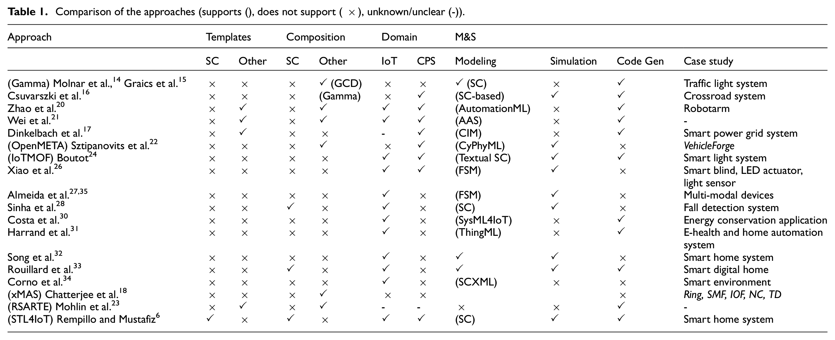
There is limited work available for facilitating the design process of such complex systems using model-based simulation techniques. Some existing research work has adopted statecharts to design the intricate dynamics of IoT and CPS systems. Their focus extends to modeling user behavior, environmental influences, control mechanisms, and interactions, underscoring the pivotal role of these elements in fortifying system models. Several of these works prioritize code generation, bridging the conceptual models with practical implementations. There is indeed a need for templates or patterns that support the design process along with a comprehensive framework for modeling, simulating, and generating code in the IoT and CPS domains. STL4IoT offers an extensive template library and toolkit for modeling and simulation of IoT systems. By leveraging statecharts and innovative modeling strategies, this research aims to make a meaningful contribution to the continuously evolving fields of IoT and CPS, providing a versatile tool for modeling a diverse array of smart systems.
4. Statechart template library
In this section, we introduce, STL4IoT, a library of statechart templates and components for modeling the behavior of IoT systems. The hub and IoT statechart templates are reusable skeletons used for building statecharts for smart systems for simulation and code synthesis. They can be easily modified and/or extended at any time according to the complexity of the system. The library also contains a collection of reusable statechart components, which can be used to model various smart IoT systems without having to build from scratch. STL4IoT is an open-source framework which contains a growing collection of components and base systems that can be considered as building blocks for developing complete, sophisticated, and complex IoT systems, through the use of Itemis CREATE or other modeling frameworks supporting statecharts. We have taken inspiration from the IoT literature25,36,37 and designed reusable atomic components and base system units that are applicable for a wide range of IoT applications.
A component can be of two types: (1) atomic and (2) base system unit. Using the IoT template, we follow the structure presented within the statechart template and reuse specific library components to essentially build the system under study. Essentially, the base units are just individual units working autonomously and the IoT statechart template is used to integrate the atomic components with the base unit to design a complete smart system. Moreover, we also developed a hub template for IoT systems that play the role of a coordinator or hub for multiple systems. The hub template can be extended by adding desired systems.
The STL4IoT library along with the components and dependencies are shown in the concept map in Figure 1. The library of templates has been implemented with Itemis CREATE Statechart Tools 10 (see Figure 2). CREATE provides support for simulation of smart system models constructed with our library and for the generation of statechart code from these models. A video demonstrating the template library is available at https://mde-tmu.github.io/STL4IoT/#demo-videos.
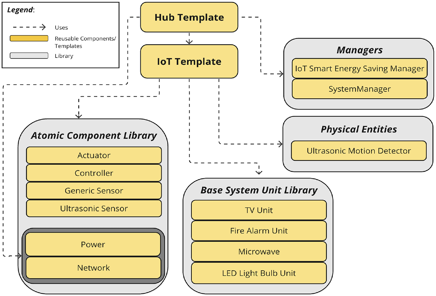
STL4IoT overview.
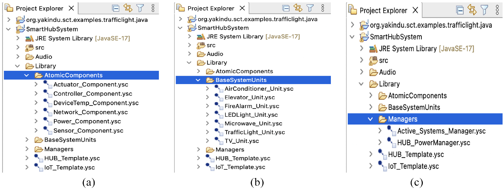
Library structure: (a) atomic components (b) base system units (c) managers.
4.1. IoT template
The IoT Statechart Template (shown in Figure 3) is used to model and represent the intricate behavior of smart systems composed of IoT components, such as, sensors, actuators and/or physical entities. Considering the complex behavior of these systems, using a template that explicitly identifies the numerous interacting components, their internal behavior, and the interactions between them would help streamline the modeling process and enhance the development, implementation, and maintenance of these systems.
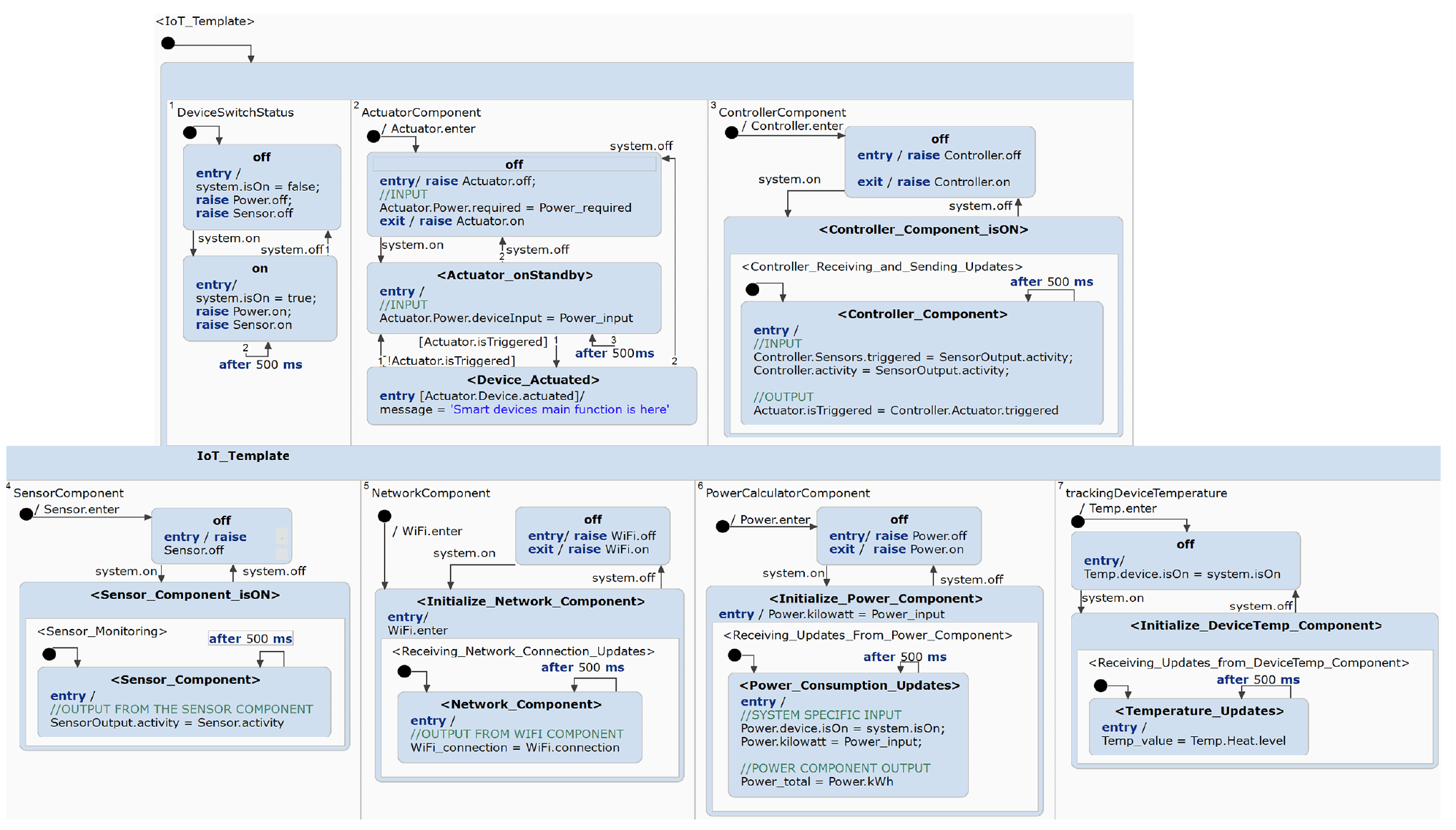
IoT statechart template (extract).
Within the template, there are orthogonal regions that are used to import the atomic components from the template library along with the pre-designed base system units into their designated regions. Essentially, the IoT Template allows users to design IoT systems using the pre-built templates and components. We have modeled the default template to have seven orthogonal regions; however, these can be extended depending on the system complexity. Once each system is modeled, it can then be added into the Smart Hub Template to design a Smart Hub System, which is used to interconnect and manage other smart systems. All systems enter a default state that contains the seven orthogonal regions. These regions have composite states that contain the components with the initial state off. When the event system.on occurs, this will also raise the on events in all connected systems.
The
4.2. Smart hub template
The Smart Hub Template (shown in Figure 4) is used to effectively model the intricate behavior and dynamics of hub systems by explicitly setting a baseline for the behavior of coordinators, in addition to supporting features, such as power and safety management.
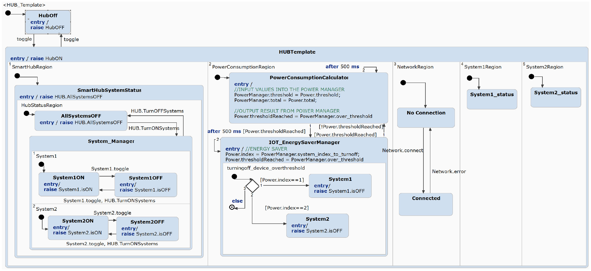
Hub statechart template.
The hub template is composed of pre-defined orthogonal states and regions that are used to manage the coordination between multiple smart systems. Figure 4 shows the regions for each IoT system controlled by the hub. To simulate a network connection between the hub and the systems, we have also added the Network component in the hub.
When applying the template, more systems can be added by adding an orthogonal region per system and reusing the state machine defined in the template. The template covers some basic functionalities: (1) turning on and off individual smart systems (see first region from the left in Figure 4), (2) turning on and off all of the smart systems at once, (3) calculating the total power consumption using the
The hub is modeled with the use of multi-state machines. When the hub is turned on via an external event, the statechart enters multiple orthogonal regions in the
4.3. Smart hub of hubs
The concept of Smart Hub of Hubs (SHoH) embodies an approach within the domain of interconnected Smart Hub Systems.38–40 SHoH introduces a novel paradigm that goes beyond the conventional capabilities of standard smart hubs, achieving seamless integration of multiple Smart Hub Systems, each with its specific functions, within a unified and efficient ecosystem.
We propose a technique to implement the hub of hubs approach using the hub template (see Figure 4). We begin by identifying the hierarchical structure of the hub of hubs scenario and determining how many layers of hubs are involved and what their specific roles and functions are within the overarching system. Each layer may represent a different level of control and orchestration. Using the hub template, we can establish clear definitions for the relationships between the hubs at different levels and define how information and commands will flow between the hubs and how they will communicate with one another. This could involve specifying interfaces, protocols, and data exchange methods. We can do this by modeling an independent hub using hub template and then proceed to importing the hub into the top-level hub.
The hub template which is used to model hub systems also allows the integration of hubs within another hub, for instance, a smart lights hub within a smart home. When importing into the top-most hub layer, the hub would be added into an orthogonal region for systems and also inside system manager as a state. This will allow the top-most hub layer to control any number of hubs that are connected to it. For example, a Smart Home Hub System can modify and send commands to a Smart Lights Hub because the Smart Home Hub System is the higher-level hub and the Smart Lights Hub is connected to it.
4.4. Atomic components
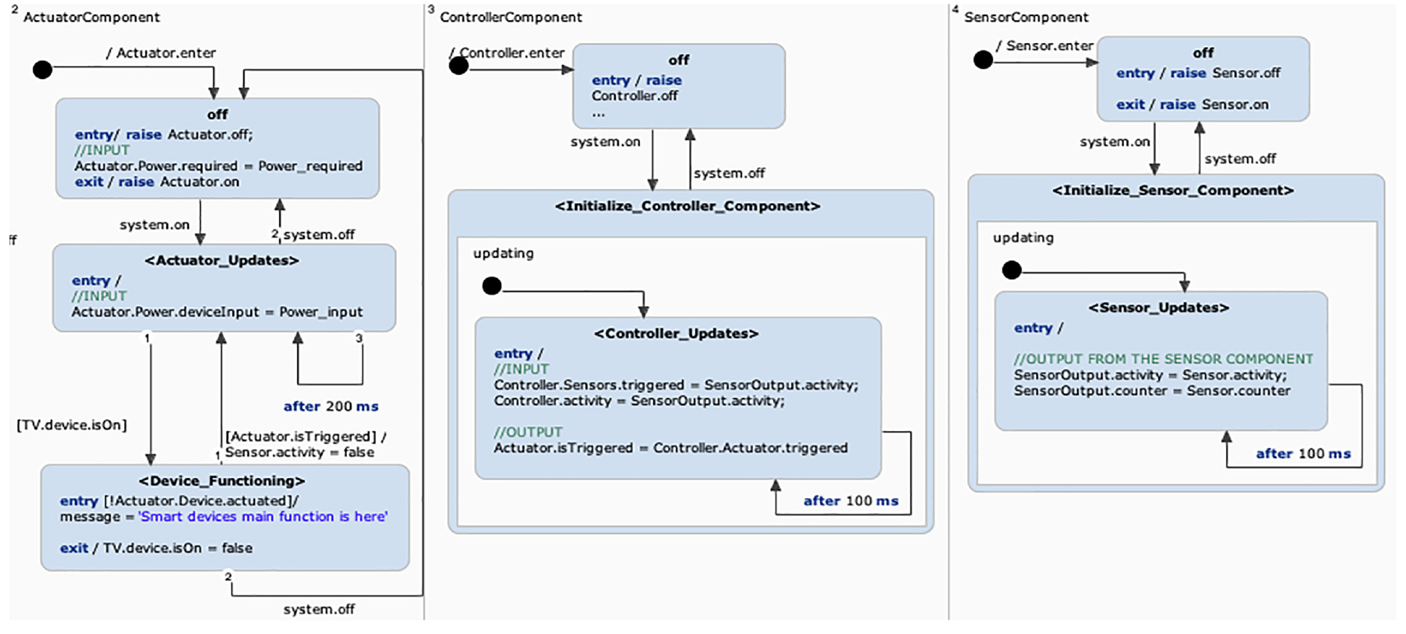
The atomic components are essential building blocks designed specifically for IoT systems. These components encapsulate basic functionalities or services that are integral to IoT applications, such as sensors, data processing algorithms, network communication protocols, and device management routines. By providing standardized and reusable units of functionality, atomic components in STL4IoT facilitate the rapid development and deployment of IoT solutions while promoting modularity, interoperability, and scalability. They serve as the foundational elements which developers can use to facilitate a more efficient modeling process. The IoT statechart template includes a composition of components that defines an IoT smart device or system. In order to properly design an IoT system, we must model the constituent atomic components. These are designed to exhibit the behavior of the heterogeneous software, hardware, and network components of an IoT system. We have modeled the IoT Template to be composed of the following atomic components:
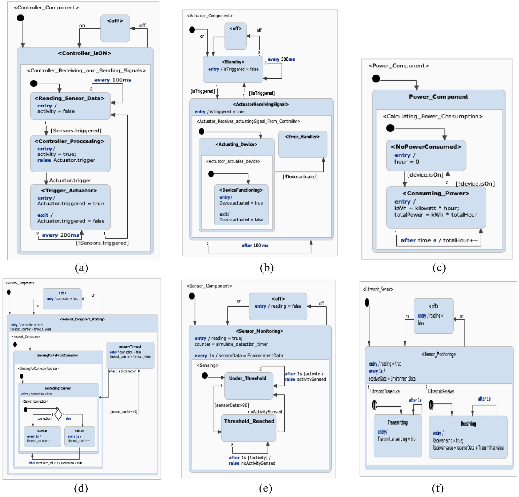
Atomic components statechart templates: (a) controller (b) actuator (c) power (d) network (e) generic sensor (f) ultrasonic sensor.
Importing atomic components via configuration panel.
4.5. Base system units
The
4.6. Physical entity
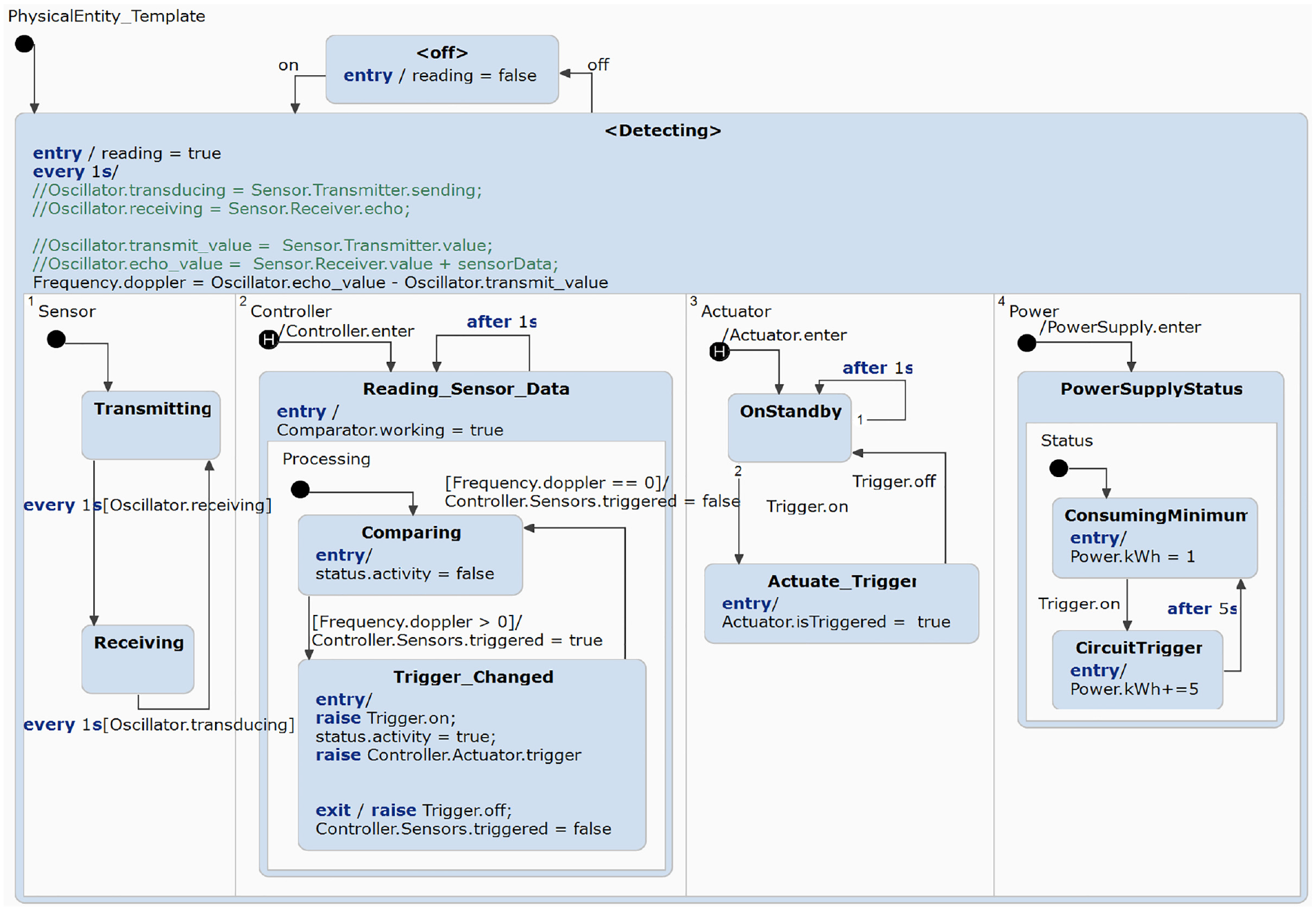
Physical entity template.
Within the
4.7. Manager components
The
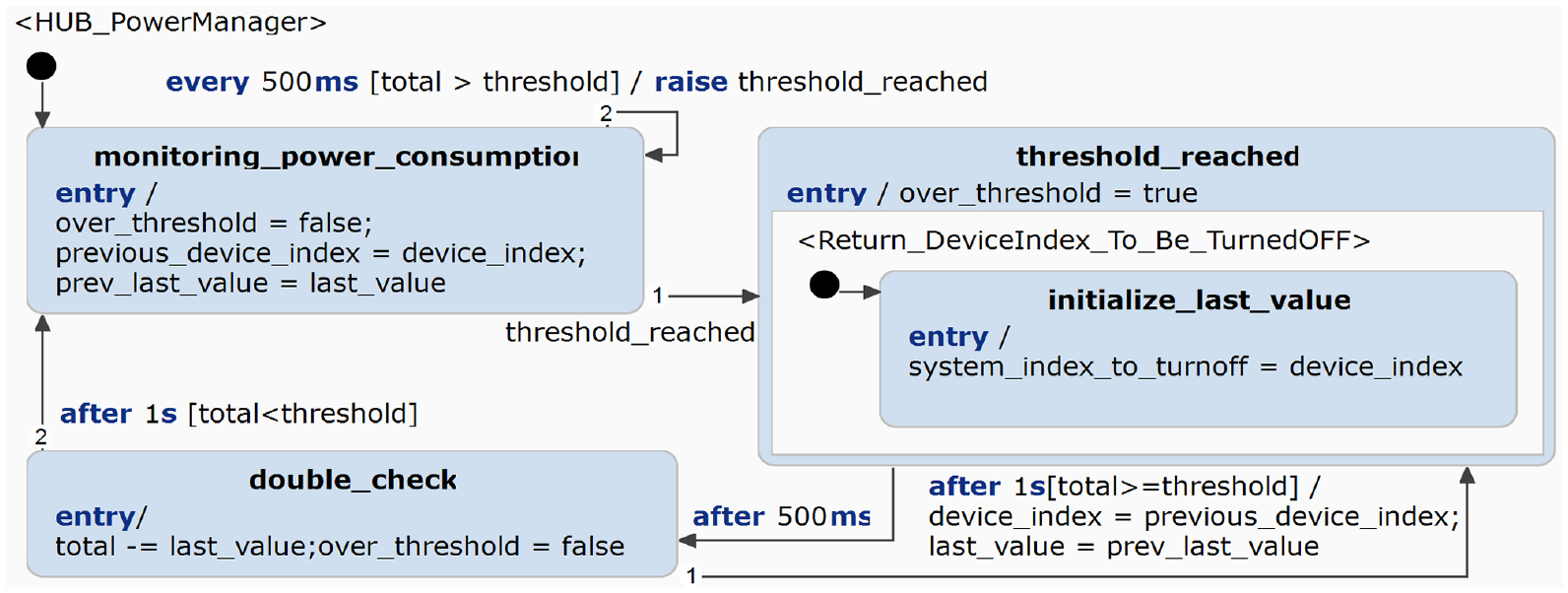
Manager component: hub power manager.
5. Using the templates
To use STL4IoT, the user must be able to understand the structure and design of the templates. The IoT template has been designed to contain all of the necessary atomic components (ie.
The following are guidelines for modelers using the STL4IoT framework built on top of Itemis CREATE.
Modeler must refer to the IoT Template when designing a smart system. If the modeler desires to model a hub to link smart systems together, then the Hub Template must be used.
Once a template is chosen, the modeler must determine which states and regions are editable.
For the IoT Template, the modeler can only edit the model by adding more
The application-specific functionality has to be added as a base system unit. The modeler can refer to the base system unit library for this; however, if the desired unit is not available, then the user will have to design their own. Adding a unit means importing the base system statechart via the configuration panel, and then assigning an appropriate variable to the statechart. This will allow for an easier use of the base system’s built-in variables and events. Once the base system and the components are finalized, the statechart can now be used as a smart system.
For the Hub Template, the modeler only needs to edit the number of smart systems connected. The hub can be connected to numerous smart systems as long as it is imported and extended properly, as shown in Figure 9. This can be done by importing the smart system statecharts via the configuration panel and assigning these to specific system variables. Doing this will allow accessibility to the smart system variables and events from the Smart Hub level.
Using the Hub Template, the designer can also model a SHoH system by defining each hub layer and integrating a hub into a higher-layer hub.
Importing statechart models in Itemis CREATE.
A systematic approach to use the hub template for designing an SHoH is described below.
Identify the multiple Smart Hub Systems that you want to integrate within your environment, each with its specific functions. The hubs to be composed are not required to be designed with the use of the Hub Template
Create a centralized hub using the Hub Template, referred to as the SHoH, which will serve as the orchestrator for these interconnected hub systems. You can import each hub system just like how you would import individual smart systems.
Utilize the hub template to design the architecture of your SHoH. This template should define the relationships and communication protocols between the various hub systems, ensuring seamless integration and efficient operation.
Once the hub design is established, you can proceed to implement it by connecting the individual instances of smart lights or other devices to the respective Smart Hub Systems and, in turn, linking these systems to the SHoH.
6. IoT application
In this section, we introduce the smart home application, which is a representative case for IoT systems.29,41 The smart home system is composed of a smart fire alarm system, a smart lights hub system, a smart TV system, and a smart microwave system. All systems are integrated into a central smart hub system.
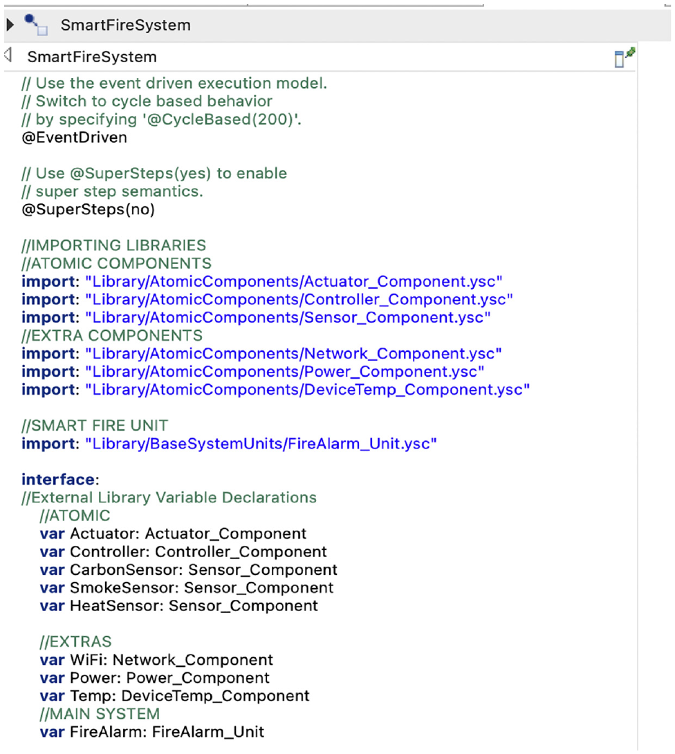
6.1. Smart fire system
The Smart Fire Alarm System is a smart system that continuously monitors the heat, smoke, and carbon monoxide levels within a monitored environment, and if any risk of danger is sensed by the sensors, the fire alarm is activated. The following describes the system’s behavior:
Smart Fire Alarm System must always start from a safe state and monitor the heat, smoke, and carbon levels within an environment.
While monitoring the smoke, heat, and carbon levels, the controller determines whether any of the levels are above the threshold.
If the threshold value is reached, the system will enter warning mode and activate the timer.
If the timer runs out and the warning status is not resolved, then the system will transition to
6.2. Smart lights system
The Smart Light System is an IoT system composed of ultrasonic sensors and actuators. An ultrasonic motion detector, which contains an ultrasonic sensor, is used to detect activity within the light’s vicinity. When it detects movements, the actuators come into action to turn on and manage the lights. The light system features an integrated WiFi component that simulates an Internet gateway connection to the server, which allows the hub to connect to the system.
Moreover, to keep track of how much energy the system is using, we have added a power component that calculates the energy consumption in kilowatt-hours (kWh). This energy data can be sent to a hub for efficient control and optimization.
The following describes the behavior of the system:
Smart lights system will always start from the
Using the
The motion detection will trigger an actuating event to activate the light.
While the lights are on, the system has a timeout caused by inactivity, which is continuously monitored by the sensors.
When the timer runs out, the lights will automatically turn off.
6.3. Smart TV system
The Smart TV System is a smart system that models a television system that has sensors and actuators. The system can either be controlled through the hub or manually through the TV unit. The system includes basic TV functionalities such as satellite channels, HDMI connection and more. The TV’s sensor component is used for monitoring inactivity, to help prevent the problem of continuous TV usage during inactivity. After a certain number of seconds of inactivity, the system will prompt the user to check if the TV is still being used. After the user’s confirmation, the system will either stay active or be turned off. The following describes the behavior of the smart TV system.
The TV system is initially off and can be turned on or off manually directly at the unit or remotely through the hub.
The motion sensors are turned on only when the system is on and will continue monitoring for activity.
When the sensors no longer detect any physical activity in the nearby surroundings, then it will start the timeout counter. After the timeout, the system will request for activity feedback from the user.
If no response is received, then after the timeout value, the system will be turned off automatically. However, if the user responds, then the system will stay on and cancel the timeout counter.
6.4. Smart microwave system
This Smart Microwave emulates the functionality of a traditional microwave oven while incorporating smart features. In addition to fundamental operations like opening and closing, setting timers, and initiating or halting the microwave, this system introduces smart capabilities. It can detect the presence of food inside the microwave using sensors, conserves power during periods of inactivity, and establishes network connectivity via WiFi. The following list describes the behavior of the smart microwave system.
The smart microwave starts in the idle mode once switched on by the user.
The system will go on active mode when the door is opened, and then it will return to idle/standby mode if there is no activity after the timeout using the timer component.
The sensor component will monitor any presence of food to ensure that the microwave is not used when empty.
The system also includes a heat sensor to monitor the internal temperature and prevent explosive accidents within the system, hence, allowing the microwave’s controller to automatically turn itself off if it reaches the temperature threshold.
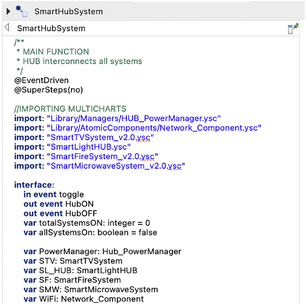
6.5. Smart hub system
The Smart Hub System is an IoT system that acts like a hub and integrates multiple smart systems and allows each one to communicate and be controlled through the hub. In this example, the smart hub for the smart home is composed of these smart systems: Smart Fire Alarm, Smart Lights Hub System, Smart TV, and Smart Microwave.
Each system works autonomously and is interconnected through the hub, which acts as the central terminal that manages the coordination of the systems. The hub device enables the user to switch on/off the smart systems, except for the smart fire alarm, remotely.
If the Smart Fire Alarm System activates the fire alarm when a fire is detected, it will notify and alert the hub. The Smart Hub will process this emergency procedure, deactivate all of the other connected systems and restrict them from being operated until the fire alarm is turned off and safety is confirmed.
Other hub features such as Power Manager are also implemented to manage the power consumption level of the home environment and ensure that the total power consumption level stays under the threshold. If the total consumption crosses the threshold, the manager recognizes this and turns off the most consuming system until the total is under the threshold again. This emulates the real-world application of circuit breakers in a household environment, which helps ensure that the household stays under the designated power circuit threshold.
The smart hub services are summarized in Figure 10 and the required behavior is detailed below.
The Smart Hub System enables the user to switch on/off the smart systems remotely including the Smart TV System, Smart Light System and the Smart Microwave System.
Using the Power Hub Manager, the system manages the power consumption level of the home environment and ensures that the total power consumption level stays under the threshold. If the total level exceeds, then the Power Hub Manager recognizes this and turns off the most consuming system until the total is under the threshold again.
When the Smart Fire Alarm System sends a critical message to the hub, the hub deactivates all of the other smart systems including the Smart TV System, Smart Light System and the Smart Microwave System. The hub restricts the user from using these systems until the danger is handled and the fire alarm is turned off.
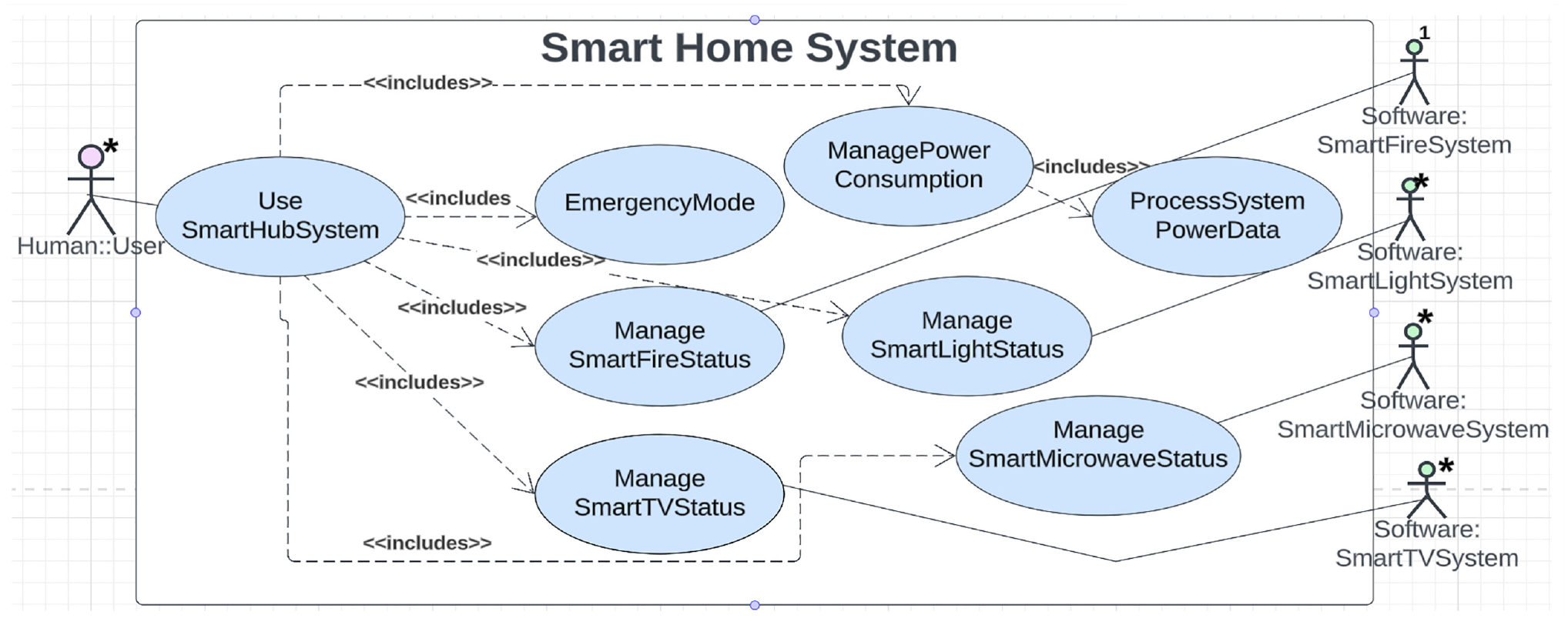
Smart hub system: use case diagram.
6.6. SHoH application: Smart hub of lights
The concept of a SHoH is the use of a central hub that serves as a unifying point for connecting and controlling multiple other specialized hubs in a network or smart home ecosystem. These specialized hubs are often designed for specific functions, such as lighting, security, entertainment, or heating and cooling. The central hub acts as a coordinator, allowing these different hubs to communicate with each other and be controlled through a single interface. Each specialized hub is responsible for controlling and managing a particular set of smart devices. For this specific example, we have a light hub system that controls all of the smart light bulbs with the environment. Moreover, we have a higher-level hub system, which connects the other smart systems and the smart hub of lights. Essentially, it acts as a bridge, translator, and controller, allowing the systems to interact with one another and automate the various devices connected to the specialized hubs. To demonstrate the SHoH concept, we have used the Smart Hub of Lights or Smart Lights Hub System which embodies the following behavior:
The smart lights hub enables the user to switch on/off multiple smart lights remotely.
Using a
When the central hub receives any system anomaly, it will deactivate all of the other smart systems including the hub of lights.
6.7. Smart home architecture
The architecture diagram shown in Figure 11, depicted as a UML component diagram,
8
describes the overall structure of the smart home system and the interactions between each smart system and its components. The model specifically describes the data flow between the Smart Hub System and the other connected smart systems. The
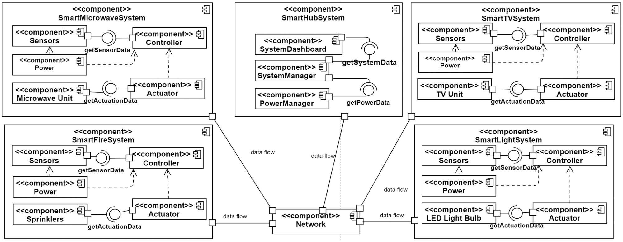
Smart home system: UML component diagram.
7. Modeling the smart home system
In this section, STL4IoT is used to design the smart home system (introduced in Section IoT Application) according to the guidelines provided in Section Using the Templates. Using the IoT Template, we have designed multiple smart systems and connected all the systems to a smart home hub by designing a main controlling hub using the Hub Template.
Prior to developing STL4IoT, we had initially modeled a few smart systems, including a smart fire system, with statecharts 5 from scratch. Despite a long and tedious modeling process, we realized that we had incomplete and imprecise models which were missing various domain-specific elements, such as the IoT atomic components. To streamline the modeling process, we gathered information on the most commonly found components in smart systems, such as sensors, actuators, controllers, and so on. We have designed statechart templates with designated regions for each atomic component, as shown in Figure 3 and Figure 13. With the use of the STL4IoT template, we ended up with more complete models for the subsequent systems modeled. We cover such as example in our demo video (https://mde-tmu.github.io/STL4IoT/#demo-videos) and discuss how the template library led to a more efficient and effective modeling process.
7.1. Smart home design
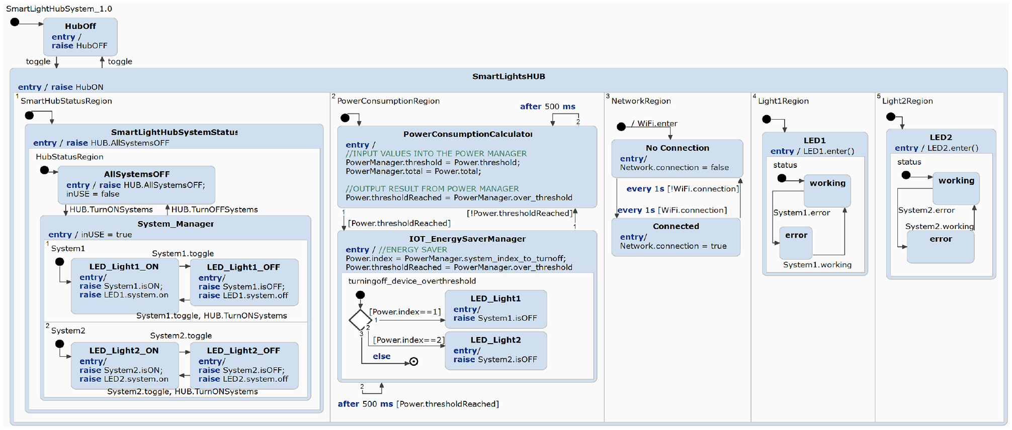
The Smart Home System statechart, was designed using the Hub Template, which aims to connect and link all smart systems located within a smart home system, as shown in the orthogonal regions in Figure 12. Once the hub system enters the on state, all of the orthogonal regions will also enter all of the corresponding initial states. For example, in the left-most region of Figure 12, the initial state indicates that all systems, excluding the smart fire system, will enter the off state. The hub system has a PowerManager component, which monitors the total power consumption of the system (see the second left region of Figure 12). The power manager continuously monitors the total power and only exits from the
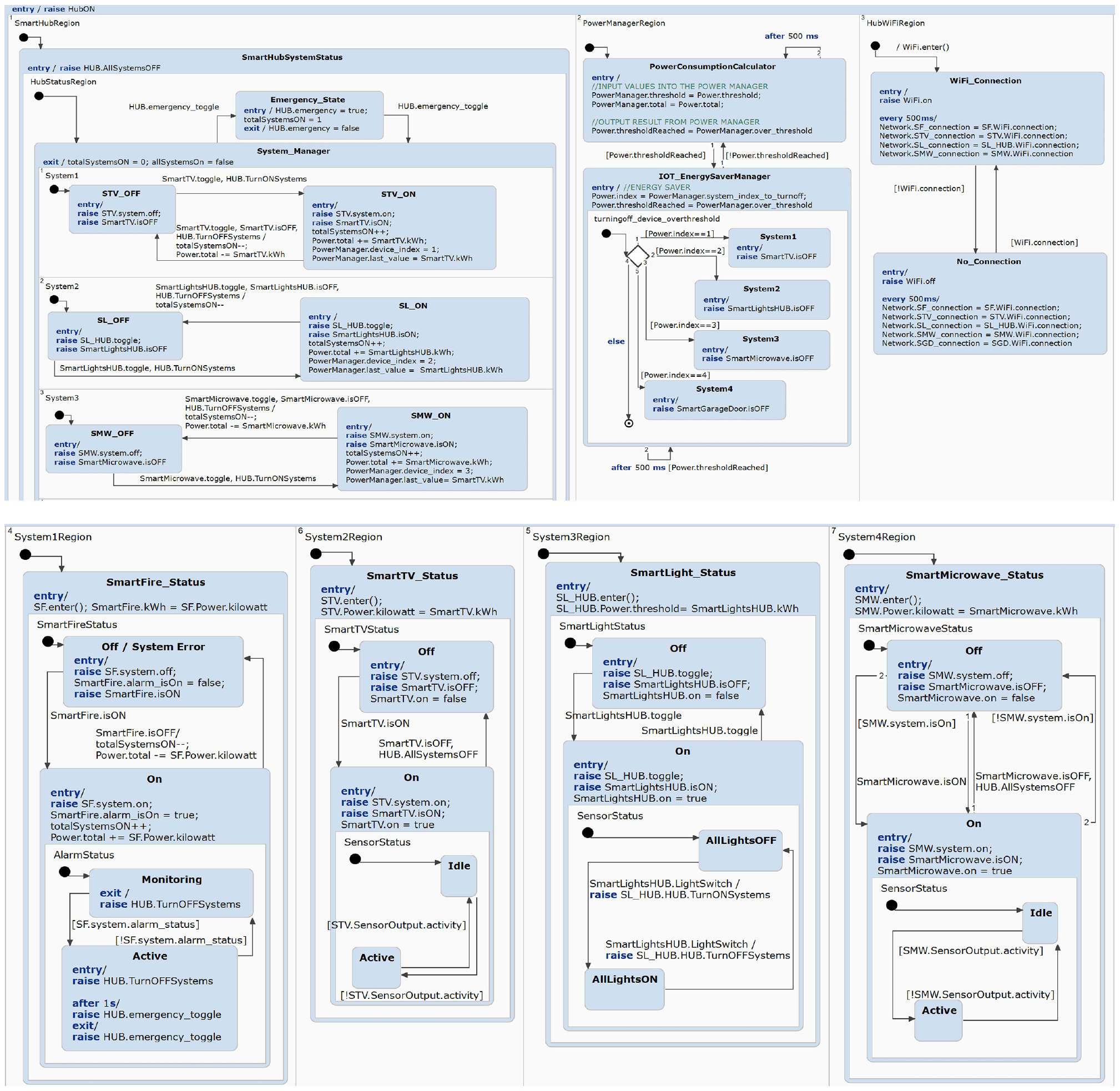
Smart home system: statechart model.
7.2. Smart fire alarm design
The Smart Fire Alarm System is composed of the main atomic components, namely
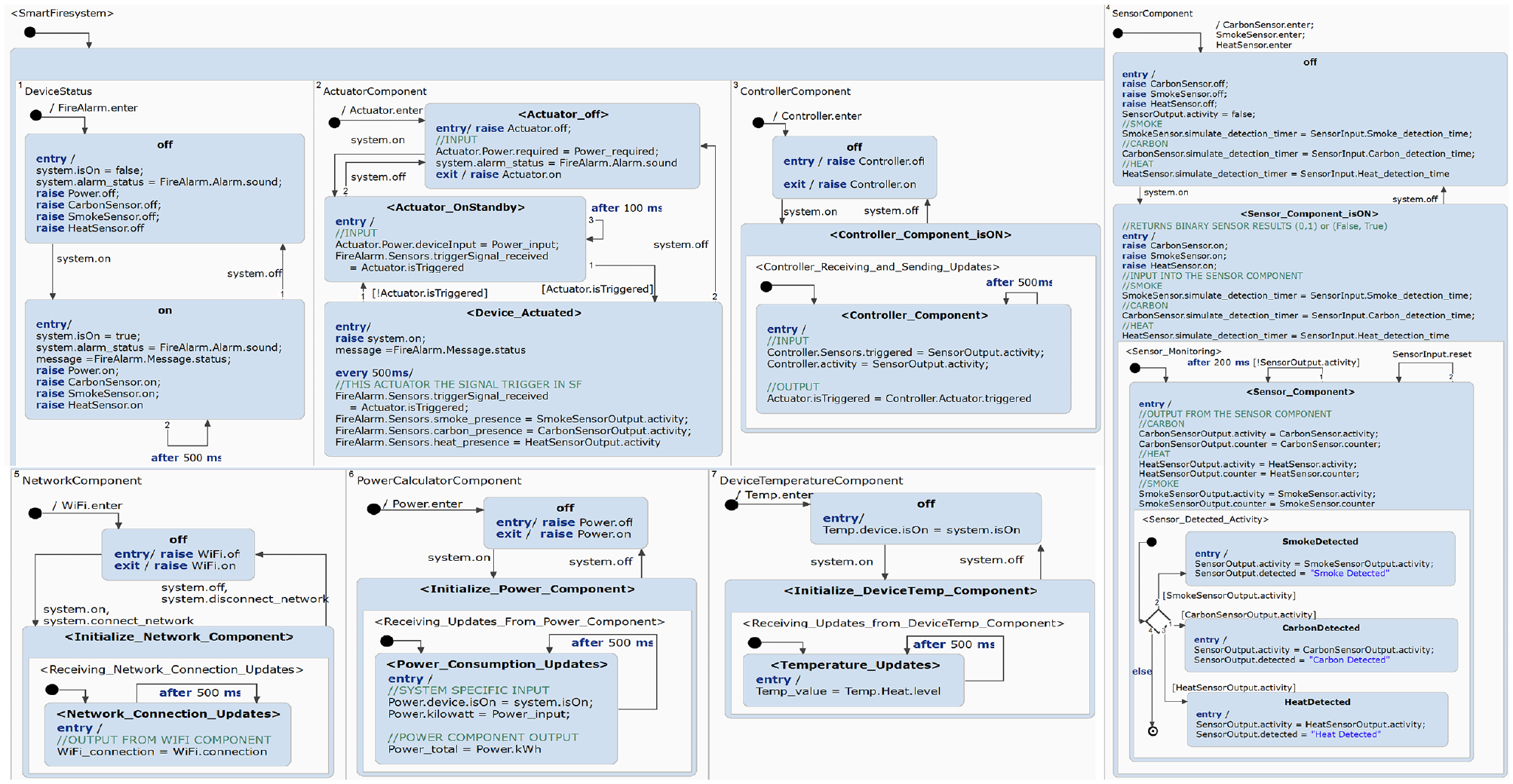
Smart fire system: statechart model.
The basic functionalities of a smart fire system are pre-designed within the base Smart Fire unit and are imported into the IoT template (see Figure 13). Once imported, the pre-defined atomic components will work accordingly. For simulation purposes, random detection times are assigned to the sensors (via the UI). Once the detection occurs, this raises an event that enables a transition to the ActivitySensed state within the
The
7.3. Smart TV design
The Smart TV System is composed of the main atomic components, such as the
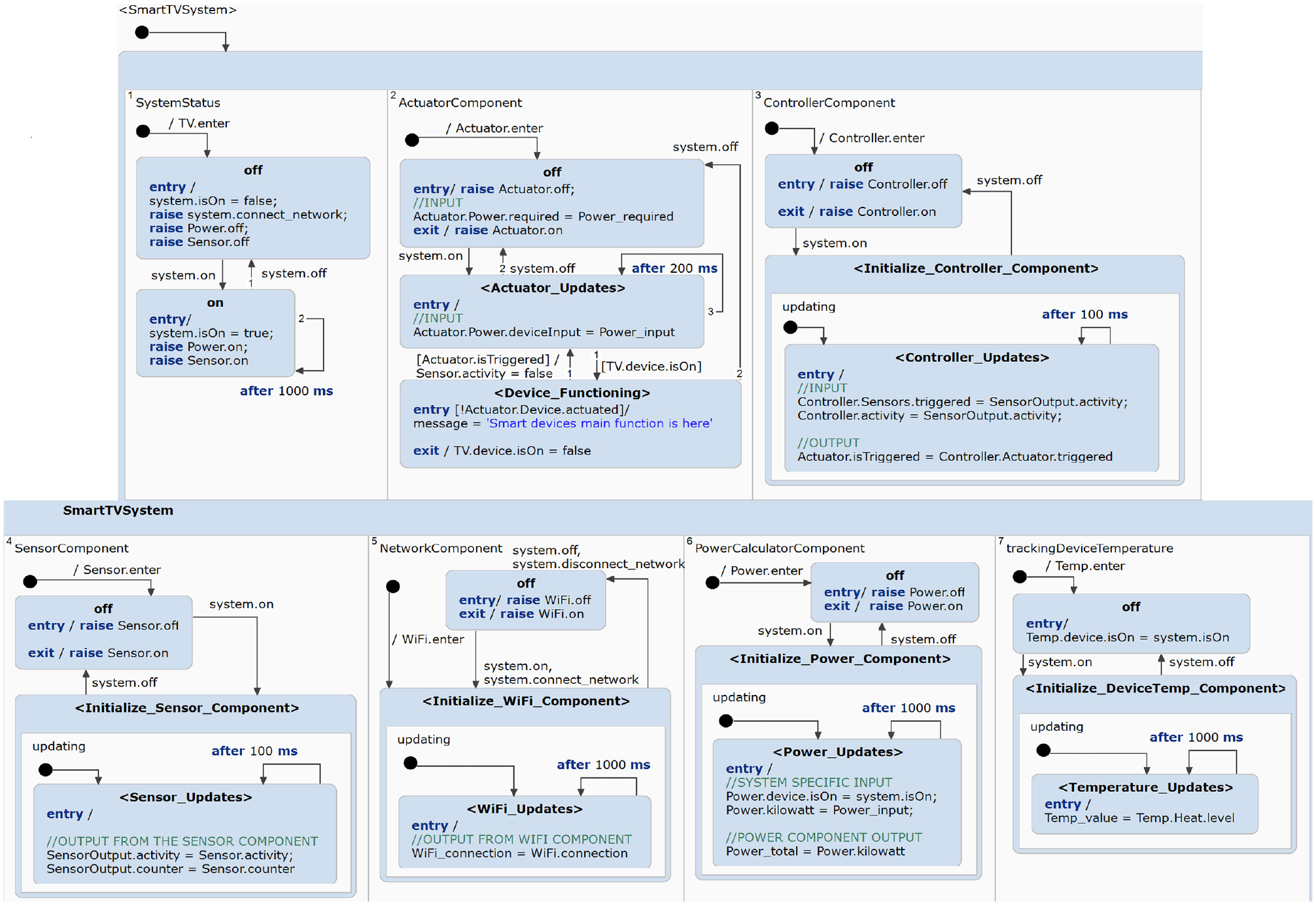
Smart TV system: statechart model.
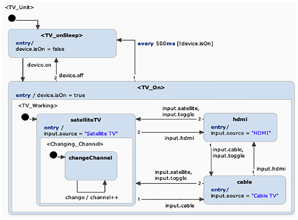
Base TV unit.
The base TV unit statechart works independently without the smart components. It models the core TV functionalities such as changing channels and managing the input sources. Additional smart components, such as the WiFi Gateway, Power Calculator, and Temperature Monitor are integrated within the template. Unlike the Smart Fire System, we use the Smart TV’s sensors specifically for detecting inactivity. The intention is to save energy when the system is not being used. The sensors will continue to monitor for activity in the near surroundings. When there is a lack of activity, the
Input/Output in Atomic Components (Extracted from Figure 3).
7.4. Smart microwave design
The Smart Microwave System is a smart system that has traditional microwave functionalities and some additional smart features. Similar to the previously discussed systems, it is composed of the atomic components,
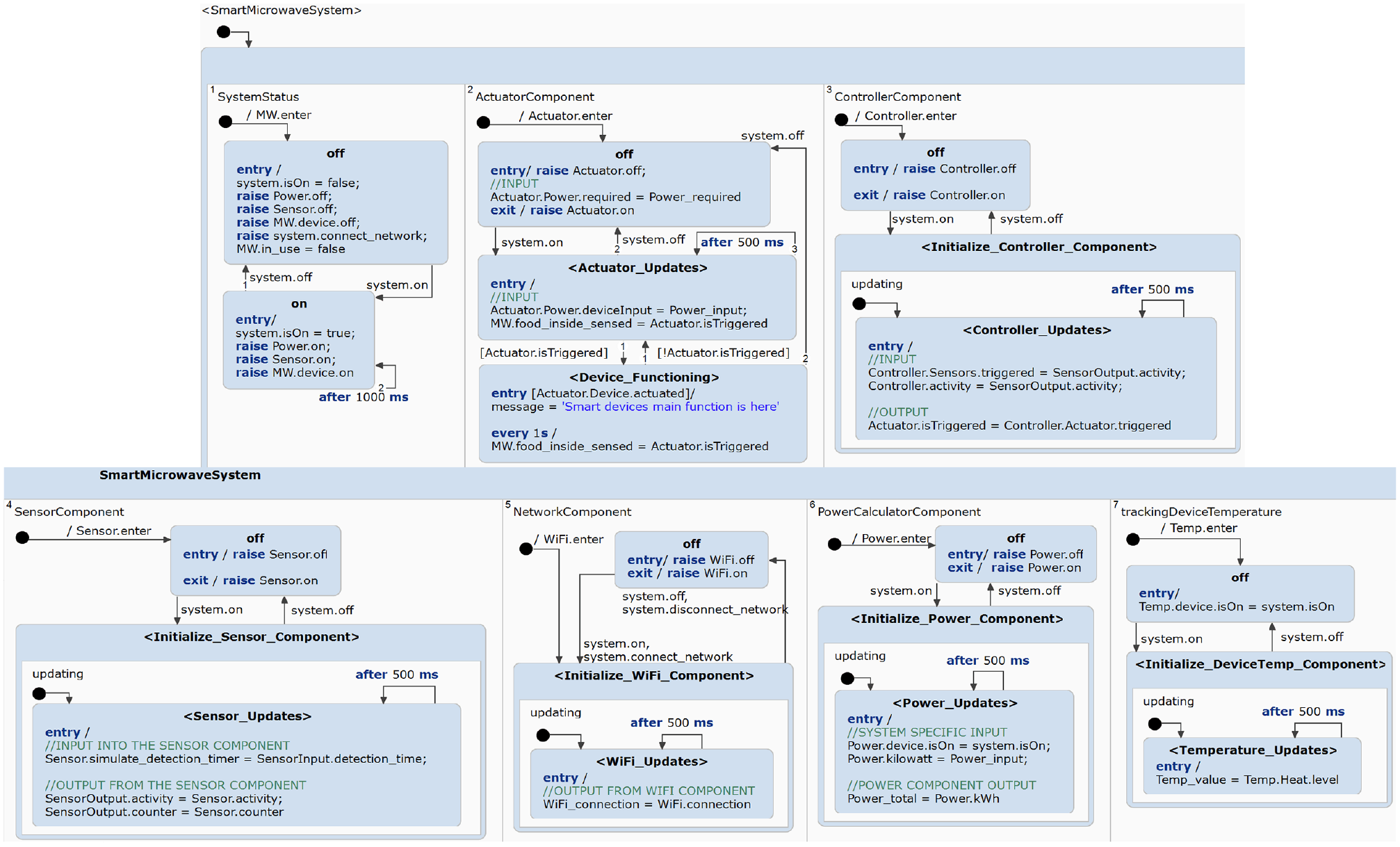
Smart microwave system: statechart model.
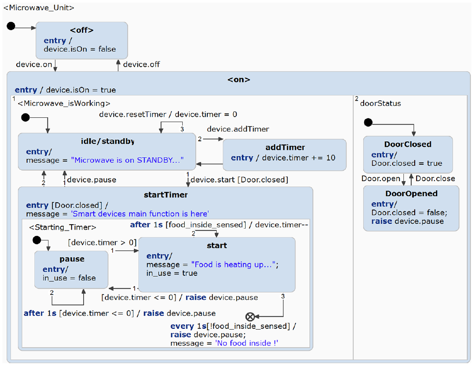
Base microwave unit.
Integrating the base
Until the
7.5. Smart light design
The Smart Lights System is implemented with the atomic IoT components,
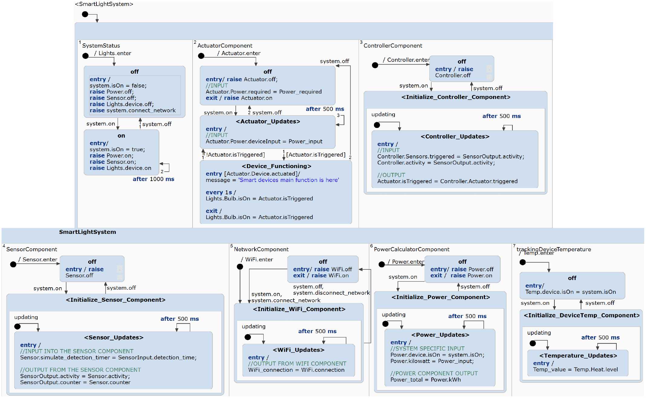
Smart light system: statechart model.
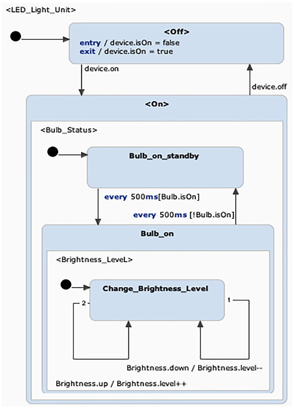
Base LED bulb unit.
7.6. SHoH concept
The successful application of the hub template at the level of the Smart Home Hub of Hubs, as demonstrated in Figure 21, validates the use of the STL4IoT approach within the domain of smart hubs. While further testing and refinements may be necessary to ensure versatility and compatibility with specific use cases, this approach provides a powerful framework for managing interconnected Smart Hub Systems and optimizing their performance within a unified ecosystem.
SHoH example: Smart lights hub statechart model.
We successfully modeled the smart systems, described in Section IoT Application, using STL4IoT. The dependencies between the library and the application-specific models are portrayed in Figure 22.
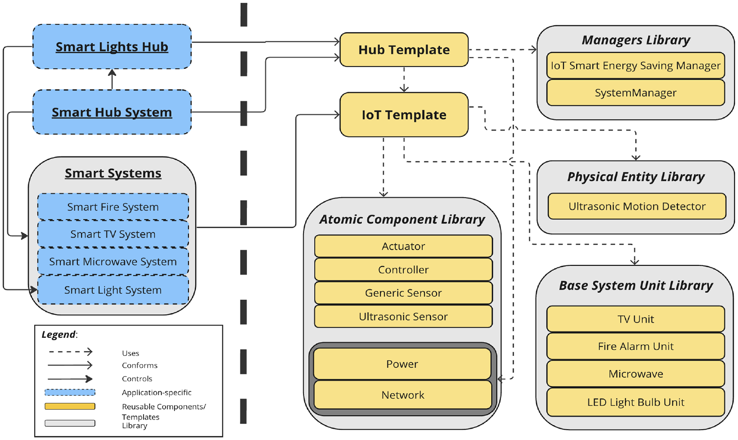
Use of STL4IoT for modeling the smart home system.
For improved readability, all of the figures included in this paper can also be accessed at https://zenodo.org/doi/10.5281/zenodo.12745242.
8. Smart home simulator
This section demonstrates that the statechart models developed using STL4IoT can form the basis for simulation and code synthesis.
8.1. Simulation dashboard
The design model created with our framework can be used to generated working code for the system controller, hence reducing the effort for creating statecharts for new systems. The code can then be integrated with a dashboard, web application, or mobile application. The generated code may also be integrated with hardware and deployed.
In this paper, we have built a training simulator for a smart home system to demonstrate the usability of the code generated from the statecharts built using STL4IoT. We have developed a dashboard with Java that serves as the user interface (UI) for the smart home. Using the code generation feature of Itemis Create, we generated Java source code from the statecharts, which is then integrated with the user interface. The tool also supports code generation in C and C ++ . The integration code is application-specific and needs to read from the statechart source code. Moreover, the source code is regenerated with every change made to the statechart.
A video demonstrating the smart home system developed with our templates is available at https://mde-tmu.github.io/STL4IoT/#demo-videos.
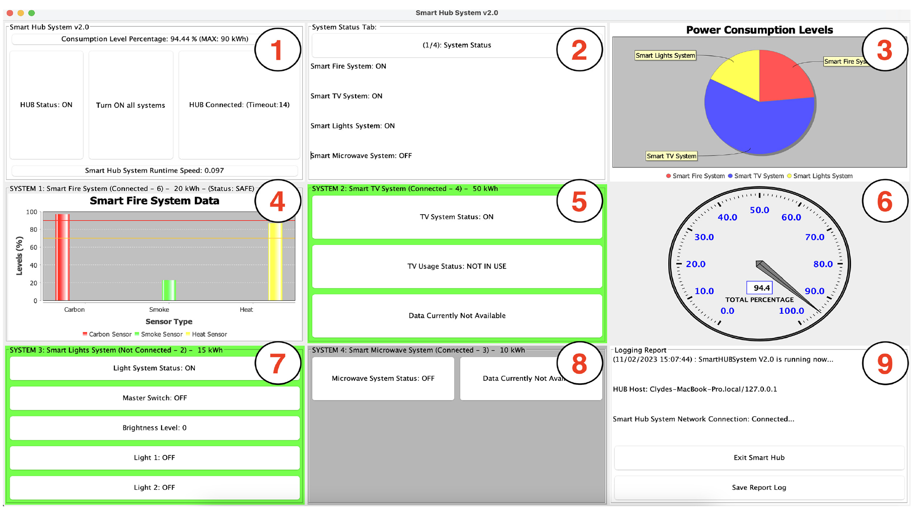
The dashboard is composed of nine panels as shown in Figure 23.
Panel 1 in the top-left displays the system status of the hub, which includes its’ network status, notification system, master switch, main hub switch and the power manager.
Panel 2 or middle-top panel indicates the status of all of the smart systems connected to the hub, such as its’ usage, power, and network connectivity status. The status can be viewed by clicking on the tab button.
Panel 3 or the top-right panel shows the percentage of the power consumed by each system in relation to the current total power consumption. The pie chart includes systems that are turned on and are contributing to power consumption.
Panel 4 or the middle-left panel displays the status of the Smart Fire System. It shows a bar graph depicting the carbon, smoke, and heat levels based on sensor readings.
Panel 5 or the middle panel contains the control system for the Smart TV System.
Panel 6 or the middle-right panel shows the total power consumption of the home environment.
Panel 7 in the bottom-left contains the control system for the Smart Lights System, which is essentially a smart hub of lights.
Panel 8 or the bottom-middle panel contains the control system for the Smart Microwave.
Panel 9 in the bottom-right is the report logging panel which logs all the reports and saves them into a data text file.
Smart home system v2.0: simulation dashboard with plots.
Moreover, we have implemented separate testing panels as shown in Figure 24. The testing panel is implemented to test the functionality of the simulator through the UI. Each button is used to simulate the process of triggering each specific sensor. For example, in the
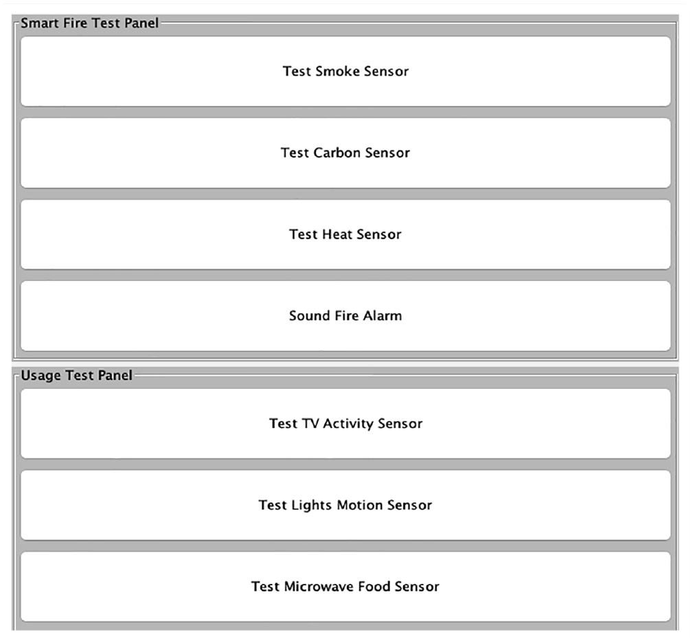
Smart home system: simulation dashboard with sample testing panels.
8.2. Simulation environment
We have also explicitly modeled the simulation environment which is responsible for generating sensor readings and configuring the data variables for each smart home system, as shown in Figure 25. The randomly generated sensor values are logged and saved into a data file and are then read by the sensors of each smart system.
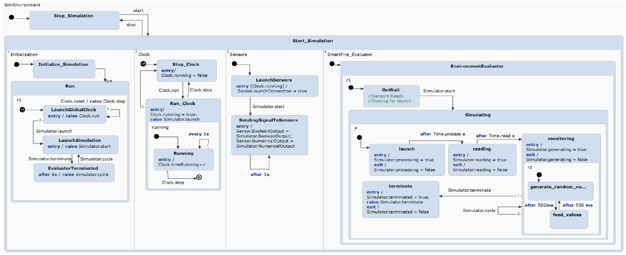
Simulation environment: statechart model.
8.3. Simulation results
We have also built support for displaying and plotting the simulation results with the data extracted from the statechart. Integration of plots in the dashboard enhances the understanding of system behavior and facilitates informed decision-making in IoT system design. In order to effectively display and plot data, we have made use of Java and Java libraries, namely JFrame (https://www.javatpoint.com/java-jframe) and JFreeChart (https://www.jfree.org/jfreechart/), enabling the visualization of data extracted from statechart’s source code.
The simulation results for power consumption are presented in Figure 23. The middle-left panel displays the change in carbon, smoke, and heat levels in the home based on the sensor readings in the Smart Fire System. The top-right panel shows the power contribution of each smart system with a pie chart, while the middle-right panel shows the total power consumption of the smart home.
9. Discussion
STL4IoT offers a versatile framework for modeling a wide range of smart systems with precision and flexibility. By utilizing statecharts, a powerful formalism for describing system behavior, STL4IoT allows developers to describe complex IoT applications clearly and intuitively. Whether it’s controlling home automation devices through a hub, optimizing industrial processes, or managing smart city infrastructure, STL4IoT provides a unified platform for capturing the intricate interactions and dynamic states inherent in these systems. Moreover, its template-based approach enables the creation of reusable and scalable models, facilitating the development of diverse IoT applications while maintaining consistency and reliability across projects. By abstracting common patterns and functionalities into reusable templates, STL4IoT promotes code reuse, simplifies maintenance, and accelerates the development of smart systems. STL4IoT offers a generalized approach that can be applied for the design of applications in the IoT and CPS domains, making it a valuable asset for IoT developers seeking to build maintainable and scalable solutions.
While STL4IoT offers significant advantages in designing complex IoT systems, it still has some limitations. One notable constraint is its learning curve, particularly for users unfamiliar with statechart-based modeling approaches. Mastering the intricacies of statecharts and understanding how to effectively translate system requirements into statechart models is a pre-requisite for using the library. Moreover, while STL4IoT provides a framework for modeling system behavior, some aspects of IoT development are yet to be supported, such as low-level device communication protocols or hardware-specific constraints. Users may need to supplement STL4IoT with other tools or frameworks to address these aspects comprehensively. Furthermore, as with any modeling tool, STL4IoT’s effectiveness depends on the accuracy and completeness of the models created by the users, which can introduce the risk of errors or oversights. Despite these limitations, STL4IoT remains a valuable resource for modeling and simulating IoT systems, offering a structured approach to capturing and analyzing system behavior.
10. Conclusion
The paper proposes a library of statechart templates to model the behavior of IoT and cyber-physical systems. Two templates, IoT template and Hub template, have been developed that provide skeletons for modeling statecharts for smart systems as well as smart hubs (e.g., a smart hub coordinating multiple smart systems in a home). An extensible library of basic atomic components modeling the different aspects of IoT systems, including hardware, software, and network, has been proposed. A generic statechart template that is reusable for various IoT systems has been designed for each of the atomic component, namely, sensor, actuator, controller, physical entity, network, and power calculator. We demonstrate the use of our templates with a representative case of a smart home system composed of multiple smart systems (smart lights, smart TV, smart microwave, and smart fire alarm) including a smart hub of lights. The templates are not just provided as documentation but have been implemented in Itemis CREATE, thus providing a platform for modelers to reuse and/or extend the models in the library for their own specific examples. The template library offers a generalized solution and can be used to design systems outside the smart home domain. STL4IoT is domain-specific, catering to the IoT domain, but is not application-specific.
As a next step, we intend to extend the set of templates to cover systems with a broader range of components, hardware devices (e.g. tags) and network connectivity (e.g. LPWAN and Zigbee). For further evaluations, we plan on using the templates to design training simulators for more complex systems, such as a smart city. Moreover as future work, we will be modeling the architectural view of the system along with the statechart model to go toward synthesizing code for deployment based on the architecture.
Footnotes
Acknowledgements
The authors would like to thank Prof. Hans Vangheluwe for his valuable insights on this work.
Funding
This work is partly funded by NSERC and Toronto Metropolitan University.
Author biographies
![]() .
.