
Abstract
Establishing digital twins is a non-trivial endeavor especially when users face significant challenges in creating them from scratch. Ready availability of re-usable models, data, functions, and tool assets, can help with creation and use of digital twins. A number of frameworks/platforms exist to facilitate creation and use of digital twins. In this paper, we propose such a platform to manage digital twin assets, create composable digital twins from re-usable assets and make the digital twins available as a service to other users. The proposed platform supports the management of re-usable assets, storage, provision of compute infrastructure, communication, monitoring, and execution tasks. Two case studies are used to demonstrate the capabilities of this platform.
Keywords
1. Introduction
Digital Twins (DTs) are used to add value to Cyber-Physical Systems (CPSs) of interest, typically called Physical Twins (PTs). At the heart of a DT is a collection of models describing characteristics of PT, which is used to provide additional services for it. Many such services can be imagined, and it is the vision of these capabilities that makes DTs so valuable: the main motivation for DTs is to enable real-time monitoring, analysis, and simulation of a PT. This technology facilitates improved decision-making, predictive maintenance, and optimisation in various industries, including manufacturing, 1 healthcare, urban planning, and energy storage. 2 DTs enhance efficiency, reliability, and sustainability by providing a comprehensive understanding of complex systems and supporting data-driven insights. They represent a natural stepping stone from the massive availability of sensors and data in different industries, and it is our conviction that DT architecture is common across many such industries.
However, the implementation of DTs is still a major endeavor, requiring a significant effort from stakeholders with different disciplinary backgrounds. For instance, establishing the communication between the PT and the DT requires potential knowledge of computer networks and architecture as well as programming skills, while building predictive models of the PT requires potential knowledge of the corresponding physics domain. Furthermore, in order to promote re-usability, a DT may marshal a collection of data sources and sinks, generic functions, and tools. Delivering such a DT can be a complex task; coordinating and orchestrating the numerous services and models remains a challenge. This is especially true because of the need for several different modeling approaches, including information models, geometry, physics, and behaviors.3,4
In this work, we present the Digital Twin as a Service platform (DTaaS). It aims to both (1) speed up development of DTs and (2) simplify its management during operations based on the notion of re-usable DT assets: data, functions, models, and other software components that can be reused by multiple DTs. A number of DT platforms have been proposed to reduce the implementation effort in relation to the structural aspects of DTs, 5 and some also recognize re-usability as a major challenge, but these platforms that support the creation and execution of DTs from composable components6,7 enforce certain implementation styles and are not service oriented. Recently, a similar idea of establishing a DTaaS platform has been proposed, 8 but with a primary focus on services related to Augmented Reality.
Our DTaaS platform targets not only re-usability in the design stage of DTs, but also re-usability at operations—different life cycle phases of a DT require different assets. DTaaS gives a practical platform to manage DTs throughout their respective life cycle.
1.1. Contribution
Our main contributions are (1) a precise definition of DT assets and DT life cycle, (2) an architecture for DT design and operations based on these definitions, and (3) an implementation of this architecture with an evaluation on the incubator 9 DT and firefighter DT of the O5G-N-IoT project. 10
1.2. Prior work
This work is an extension of previous work from the co-authors which has introduced the foundations of DTaaS, 11 its nomenclature and life cycle phases for DTs deployed in the platform.
This manuscript introduces the definition of a re-usable DT asset, an extended and adopted architecture to support this definition, and two realistic case studies as an evaluation. The current manuscript also expands on prior work by providing details about how two case studies have gained from establishing DTs using DTaaS. From those case studies, we describe the benefits of re-usable assets, the use of different life cycle phases, the realization of the DTs and their performance evaluation. Moreover, we provide a more detailed comparison with existing platforms, and introduce two new re-usable commonly used DT services (visualization and alerts).
1.3. Structure
The rest of this paper is structured as follows. We first introduce Background and Related Work in DT platforms. Afterwards, we introduce the two different Case Studies (a DT for food fermentation and a DT for rescue mission support in firefighting), which are consequently used as running examples for illustration. Then we give the definitions and illustrations for Re-usable Digital Twin Assets, Digital Twin Definition, and Phases in Digital Twin Life Cycle, before we give an overview of the system architecture and its platform implementation. We provide feature comparison of DTaaS with other DT platforms in platform implementation. Afterwards, we illustrate the implementation of case studies on the platform and describe the performance evaluation. The paper ends with discussion and future work and concluding remarks.
2. Background and related work
2.1. DT definition and realisation
In abstract, DT is a digital representation of a physical object (PO), which influences the future behavior of the PT. However, this definition hides the variants and possible interpretations.9,12 In this manuscript, we refer to DT as a software running remotely in conjunction with cloud services that collectively add value to an existing PT through the use of models and simulations. 13 Some of the existing literature proposes three subcategories of DTs: 14 (1) Digital Model (DM), in which PO and DO have no automated exchange of data, (2) Digital Shadow, where PO emits data to the DO automatically, and finally (3) DT, in which case, there exist a two-way automated data exchange between the DO and PO. Only in this case, the PO is referred to as a PT. Nevertheless, a DT should be created to accomplish certain business goals, that is, in terms of optimisation or provision of insights, 15 and therefore, the inclusion of simulation models, inference and reasoning mechanisms, and data analysis become essential. 16 The orchestration for including these components toward achieving the business goals of DTs is called the DT constellation. 17
A five-level DT architecture has been proposed previously. 18 On the lowest level (1) Smart Connection, resides the data exchange between DT and PT; (2) Data-to-information conversion, concerns conversion and aggregation of data for monitoring and to make it useful for (3) Cyber, which is the central information hub and source of analysis across multiple data sources. At level (4) Cognition, the knowledge acquired from lower levels are made available for decision-making, and finally at level (5) Configuration, is where decisions or reconfiguration from the DT is fed back to the PT, to make it self-adaptable. Thus, to create a DT, infrastructure, tools, models, and configurations must address each level.
In the DT platforms discussed next, we focus on those that promote the implementation of the (3) Cyber and higher layers, choosing to leave out platforms whose goal is to enable the Smart Connection and Data-to-information conversion layers, as platforms falling in this category have been surveyed before.16,19
2.2. Re-usability in DT implementations
Completely new development of a DT for each PT is not necessary if the DT or its parts are re-usable. 20 DTs should therefore be engineered and operated by reusing the parts previously developed for other DTs. Toward this end, we highlight two approaches, detailed next: asset reuse and code generation.
2.2.1. Asset reuse
A prior work in the HUBCAP and DIGITbrain platforms 21 shows that a DT can be structured to be composed of re-usable assets other than models. The DIGITbrain project 22 introduces the notion of four re-usable assets: data, models, 4 algorithms, and behaviors. The software tools and frameworks have also been included in the algorithms asset. Each behavior contains a pair of model and algorithm. The data and behaviors assets are selected and configured to create new DTs. Such re-usability can also be seen in both medical, manufacturing, and maritime DTs.6,23–26 The Digital Twin Platform Stack Architectural Framework of Digital Twin Consortium 27 proposes data, multiple representations of models (both static and computable), algorithms and services as re-usable assets.
Knowledge graphs 28 have been recognized early as a possible technology that can be used to configure DTs. 29 Subsequently, several DT architectures have used knowledge graphs. The SINDIT 30 is a component-based framework and architecture for rapid prototyping of DTs that uses knowledge graphs to represent the relationship between assets. A few cognitive twins 31 have used ontologies to connect simulation units 32 and component description. 33
2.2.2. Code generation
An alternative to re-usable assets is the use of code generation techniques, informed by domain-specific languages (DSLs) descriptions, to generate DTs. 20 The proposed DSLs describe domain, data, tagging, constraint, and graphical user interface (GUI) as input to a set of generation tools, to create the application-independent parts of a DT platform. The proposed platform can then be tailored by a domain expert for a specific purpose, using a web-based front-end.
We argue that code generation approaches are complementary to asset reuse since the configuration of such assets can be generated by means of a DSL. Several commercial and open-source projects propose DSLs to specify composition of a DT as a configuration of models, relations, and data exchange. 34
Microsoft Azure’s Digital Twin Description Language (DTDL) 35 and Eclipse Vortolang 36 provide object-oriented modeling capabilities, such as class, property, method, and association, as well at specifying data exchange endpoints. 34 The commercial platforms have come up with their own DT DSLs. 5 Examples include DTDL for Azure DTs, Eclipse Hono, 37 Eclipse Ditto, 38 and also AWS IoT twinmaker. 39 Other platforms, such as Eclipse BaSyX 40 are designed based on the Asset Administration Shell (AAS) meta-model, which is one of the outcomes of the German initiative Reference Architectural Model Industrie 4.0 (RAMI 4.0), 41 which recently turned into the IEC 63278-1:2023 Standard. 42 Some of these platforms and frameworks have been previously analyzed.5,16 A feature comparison of these platforms and DTaaS is available in Comparison with Existing Platforms.
2.3. Comparison with related work
DTaaS takes a complementary approach across different DT frameworks and platforms. Multiple prior surveys16,43,44 compare existing DT frameworks based on system architecture, interoperability, scalability, reproduction of previous results, and composition. DTaaS intends to provide the infrastructure where complementary services can be orchestrated to run and maintain DTs with a well-defined DT asset configuration. Hence, there can be coexistence of existing DT platforms and DTaaS. 45
DTaaS provides two additional features not available in comparable DT platforms, namely, (1) providing private workspaces for authoring and verification of re-usable assets and (2) enabling sharing of DT assets to foster collaboration and re-usability.
Some of the challenges in the theory-to-practice transition of DT platforms are the support for different operating phases of the DT and the orchestration of services.16,46 DTaaS development process addresses these challenges by following successful software engineering practices such as microservices, DevOps, and GitOps, which have found their way into the development and operation of DT platforms.47,48 In addition, it can include extended functionalities to perform verification of the published assets with DevOps 49 and provisioning of DT execution infrastructure by using Git workflows. 50
In DTaaS, the user is presented with two ways to work with a DT. In the simplest form, a pre-existing pre-packaged DT is made available on the platform. For example, a DT can be realized as a set of tightly coupled services that exchange messages and stream data to/from a PT. Some of these services can execute models to provide their services. This form of DT is consistent with the DT implemented for an incubator machine.9,51 In this case, the DT as a whole is re-usable. However, the services and the embedded models are tightly coupled preventing their reuse. The need for more enhanced re-usability motivates the second realization of DTs which is the focus of this paper. In this paper, a DT is realized as a set of re-usable assets are categorized as Data assets, Model, Function, and Tools. A key innovation in our platform is that these four categories of assets, detailed later in Re-usable Digital Twin Assets, can be declared in the platform by the user and made available to be reused by other users wishing to build DTs.
2.4. Monitoring of DTs
Monitoring of DTs and there by their linked PTs is one of the use cases for DTs. Runtime monitoring tools are suitable for creating monitors especially from safety properties defined on either DTs or PTs. The Temporal Stream-based Specification Language (TeSSLa) 52 has been used to integrate monitoring into the described firefighter DT. TeSSLa refers to both a specification language and an associated tool-chain developed within a community-driven open-source initiative. 53
The fundamental principle of TeSSLa lies in its ability to describe transformations of data streams from inputs to outputs. It can be used within DTs to monitor (1) data from PT and (2) predictions of DT. In both cases, the deviations can be reported to either users or to decision-making software.
TeSSLa specifications are constituted by a set of input stream declarations. The specification defines derived streams created by applying specific operators to the input and previously defined streams. Some of these derived streams are designated as the specification’s output streams. TeSSLa provides libraries and supports the creation of macros. Macros are user-defined stream operations constructed from the core operations or other macros, thereby aiding the specification of complex properties. TeSSLa specifications allow for the creation of advanced output streams, including statistical data, with timestamps for events and support compiling into monitors binary, executable monitors that may be integrated into DTs.
3. Case studies
3.1. Incubator
The incubator PT is a box containing a heater and a fan connected to a controller that can turn on and off the heater/fan. The controller is supported by temperature sensors placed inside the box. The incubator has a single requirement which is to save energy if the user forgets to close the lid, or simply misplaces it. The incubator PT is used to produce tempeh, 54 which is a food produced by growing mold around soybeans. The original method for producing tempeh, discovered in Indonesia, consists of: (1) Hydration of soybeans: Soybeans are soaked either overnight in cool water or for a shorter period in hot water. (2) Removal of skins: The hydrated beans are rubbed together with water, either before or after cooking, to remove skins. The loosened skins float away with the water. (3) Partial cooking: The beans are partially cooked by steaming or boiling, retaining firmness. (4) Inoculation: After cooking, all liquid is drained, and the beans are inoculated with scrapings from a previous fermentation. (5) Fermentation: The inoculated beans are wrapped in banana leaves and placed in a warm location to ferment. Mold mycelia bind the beans into a compact cake, and enzymic digestion softens individual beans. (6) Further processing: Raw tempeh can be sliced and dried, roasted, cooked in soup, or deep-fried before consumption.
The incubator is designed to support the fermentation process, where the user is expected to open the box lid to inspect its contents and determine whether the fermentation has been concluded. Figure 1 shows an example tempeh production process at the beginning (left), halfway through (middle), and finished (right). As can be seen, the mold mycelia in white grows around the soybeans, consuming them and becoming a compact cake. What makes this case study deceivingly simple is the fact that at its highest growth rate the tempeh switches from being a heat sink into a heat source, 54 effectively changing the dynamics of the system. This effect varies substantially from batch to batch because it is a biological system and depends on the number of factors such as the amount of starter mold as well as its genetics. Detecting the open lid is just a simplified use case of the DT used in this paper to illustrate the DTaaS platform.
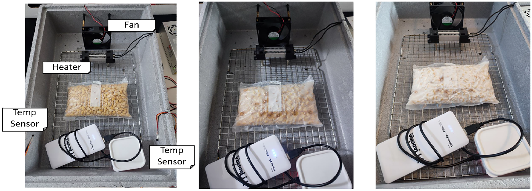
Example fermentation of tempeh using the incubator PT at the beginning (left), halfway through (middle), and finished (right).
3.2. Firefighter
The firefighting scenario, part of the O5G-N-IoT project, 10 aims to enhance decision-making and operational safety in emergency response situations. Firefighters equipped with self-contained breathing apparatuses (SCBAs), including oxygen tanks, operate in hazardous, rapidly changing environments. This scenario presents various challenges that necessitate quick, informed decisions based on accurate, real-time information.
Current firefighting practices involve firefighters periodically reporting their oxygen tank pressure to a mission commander. This method suffers from delays in information updates and the potential for human error, hindering real-time situational awareness. In contrast, a firefighter DT offers continuous, real-time monitoring and automatically updating crucial data like oxygen levels and firefighter locations. Using a firefighter DT significantly improves response strategies, adapting quickly to changes in the operation.
The primary requirements 55 for the firefighter DT are continuous monitoring of firefighters’ oxygen levels and locations within the building, providing actionable insights to the mission commander based on real-time data, and ensuring the safety of firefighters by predicting oxygen depletion and recommending safe exit routes. The primary challenge is ensuring firefighter safety while maximizing operational efficiency, which involves continuously monitoring SCBA oxygen levels and navigating through the building using real-time data. The firefighter DT and the coupled PT can also be used to simulate emergency missions.
The firefighter DT described in this paper requires the existence of localization services and the continued validity of the building model. The building under fire likely undergoes structural deterioration and transformation. If the changes in the building significantly deviate from the building model used in the firefighter DT, then the predictions made by the DT become invalid. Another limitation could be the over-reliance on a robust localization service in a very dynamic environment (building under fire). The current version of firefighter DT is not capable of handling intermittency in localization service. Further explanation on the limitations of the firefighter DT in terms of data collection, necessary prerequisites, and scope are available in a previous publication. 55
4. Re-usable DT assets
In the following sections, we introduce the core notions needed for an architecture for a DT platform that facilitates reuse of different models, tools, and other heterogeneous components:
The DT assets, which represent the smallest elements of a DT that can be reused.
The Digital Twin Definition itself, and its composition from DT assets and services as DT configuration.
The Phases in Digital Twin Life Cycle, and their relation to DTs.
The System Architecture that connects all these.
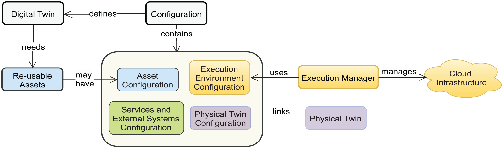
The relation between these concepts is shown in Figure 2.
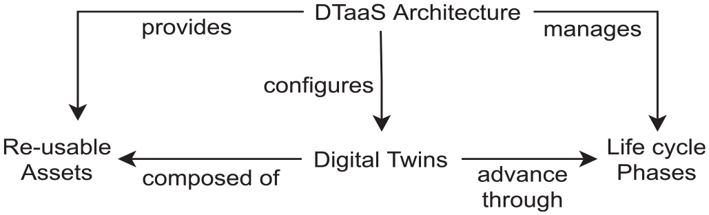
Relations between central concepts.
Let us turn to re-usable DT assets first. DTaaS treats DTs as having re-usable assets. In short, a DT asset is the smallest element of a DT that can be reused. These assets are put together and configured in a certain way. We use four categories of assets: data (D), model (M), function (F), and tool (T). This section provides explanations for categorisation of DT assets.
The data (D) asset refers to data sources and/or sinks available to a DT. Typical examples of data sources are sensor measurements from the PT and test data provided by manufacturers for calibration of models. Typical examples of data sinks are visualization software, external user software, and data storage services. There exist special outputs such as events and commands which are akin to control outputs from a DT. These control outputs usually go to the PT, but they can also go to another DT. 56
The model (M) assets are used to describe different aspects of a PT and its environment, at different levels of abstraction. Therefore, it is possible to have multiple models for the same PT. For example, a flexible robot used in a car production plant may have structural model(s) which will be useful in tracking the wear and tear of parts. It can have a behavioral model(s) describing the safety guarantees provided by the robot manufacturer. It can also have a functional model(s) describing the part manufacturing capabilities of the robot. Models have inputs, outputs, states, and parameters, as well as initial values for states, following the nomenclature of the Functional Mockup Interface (FMI) 57 standard.
The function (F) assets are primarily responsible for pre- and post-processing of data. The data to DT come from either PT or databases. These data are used for evaluation of models. Given that a DT might have multiple models, the data (and its format) required are not going to be the same for all of them. This observation is acutely true in cases of models developed long after data have been captured. Another case is that of normalization and unit conversion of data; well-implemented pre-processing functions help with this task. In the same vein, post-processing functions help with the conversion of model outputs into valid control inputs to PT. One such example is that of controlling a machine speed based on predictions of a machine learning model. The model provides normalized (say zero to one) prediction which must be converted into actuator input for the machine.
The software tools and frameworks (in short, tools) contain implementations of engineering domain-specific or generic computer algorithms. A few examples of domain-specific algorithms are: SIMPLE (computational fluid dynamics), Barycentric method (graph drawing), SPICE and Xyce (electronic circuit simulation), ant colony optimisation (genetics), and generative adversarial networks (machine learning). A few examples of generic algorithms are: Newtons method (numerical), Bubble sort, and Strassen matrix multiplication. Domain-specific tools such as Maestro CoE 58 contain implementation algorithms for conducting co-simulation. Same is the case with OpenFOAM 59 and TensorFlow. 60 On the contrary, MATLAB 61 is an example of a tool that has implementations of algorithms coming from many engineering domains.
These tools are executed on top of a computing platform, that is, an operating system, or virtual machines (VMs) like Java Virtual Machine, or inside Docker containers. The tools are used to create, evaluate, and analyze models. Most models require tools to evaluate them in the context of data inputs. There exist cases where models and tools are combined. The combined entity is run in the same way a tool is run.
4.1. Incubator
Let us now investigate the assets used in the incubator case study. Figure 3 provides an overview, and we detail the different kinds of assets next.
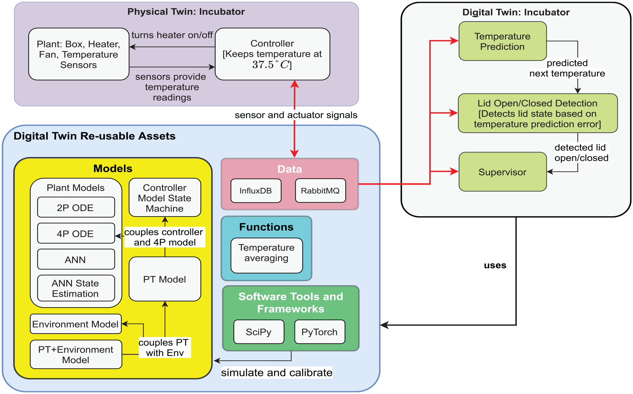
Summary of the assets used in the incubator running example.
The incubator DT therefore has the single requirement: to save energy if the user forgets to close the lid, or simply misplaces it. This requirement is implemented by the following DT services:
Temperature Prediction—Responsible for predicting the average temperature in the box at time t + H from the average temperature, control actuation, and room temperature, at time t. This service is triggered whenever a new control actuation is issued.
Lid Open/Closed Detection—Detect and signals, whether the incubator lid has been opened or closed.
The above services work together to fulfill the energy saving requirement as follows:
The open lid detection service compares the temperature predictions with the actual temperature, and when there is a deviation, it signals the lid as being open.
The supervisor then re-configures the controller accordingly to save energy by placing it in a low power mode.
We refrain from giving more details about how these different services coordinate, which is explored in prior work, 9 and focus on the assets used in the incubator DT.
The data assets are an InfluxDB time-series database and a RabbitMQ broker. The InfluxDB time-series database acts both as data store and visualization service. The RabbitMQ endpoint acts as bidirectional communication broker between PT and DT.
An example function is the calculation of the average between the two temperature sensors installed inside the box. If analogue temperature sensors were to be used, one would also need smoothing functions to eliminate the noise from the temperature measurements.
The models are:
4.1.1. Plant models
The incubator case study uses four different models for the plant itself, each for a different aspect.
2-Parameter Model: A simple scalar ordinary differential equation (ODE) representing the plant dynamics. It takes as inputs the room temperature, the state of the heater, and returns as an output the average temperature of the air volume inside the box. It contains two parameters related to the box-walls heat conductivity and air heat-capacity.
4-Parameter Model: A plant dynamic model (ODE) that takes as inputs the room temperature, the state of the heater, and returns as an output the average temperature of the air volume inside the box, as well as the temperature of the heating element.
ANN Model: A neural network–based model, which takes as inputs the room temperature, the state of the heater, the previous average temperature of the air volume inside the box, and returns as output the average temperature of the air volume inside the box.
ANN State Estimation Model: A neural network–based model, which takes as inputs the room temperature, the state of the heater, the previous average temperature of the air volume inside the box, and returns as output the average temperature of the air volume inside the box as well as the temperature of the heating element.
4.1.2. Controller model
A controller model (state machine), which takes as input the average temperature of the air volume and outputs the state of the heater.
4.1.3. PT model
A hybrid automata model. The input is the room temperature, and the set of parameters is the union of the four-parameter model and the controller state machine model.
4.1.4. Environment model
A simple algebraic model
4.1.5. PT + environment model
A model coupling the PT and Environment models.
Finally, tools such as the numerical solver from SciPy, 62 and the neural network framework PyTorch 63 are used.
4.2. Firefighter
The firefighter DT continuously monitors self-contained breathing apparatuses (SCBA) pressure levels and firefighter locations. If the oxygen level is deemed too low in relation to the fastest escape route, the DT alerts the individual firefighter. It also recommends the quickest and safest exit route based on the current location of the firefighter and building layout. DTaaS user in this scenario is a firefighter sub-contractor or mission controller, who deploys and adapts the system before firefighting missions take place.
Figure 4 provides an overview of re-usable DT assets used in the firefighter DT. The data used in this DT are provided by a mock PT (mock firefighter). Simulated SCBA pressure data and location data from inside of the building are sent to a MQTT broker to be ultimately used by the DT. The communication between PT and DT is based entirely on MQTT topics. Thus the DT case study outlined in this paper works for a real firefighter PT as long as the location and oxygen level data are sent to the DT. It then produces a prediction on mission time and raises an alarm if the oxygen level is deemed too low. The remaining mission time is also stored in InfluxDB—a time-series database. The InfluxDB acts as data storage. Real-time data visualization using InfluxDB and Grafana dashboards displays crucial information such as oxygen levels and remaining mission time for the usage by the mission controller.
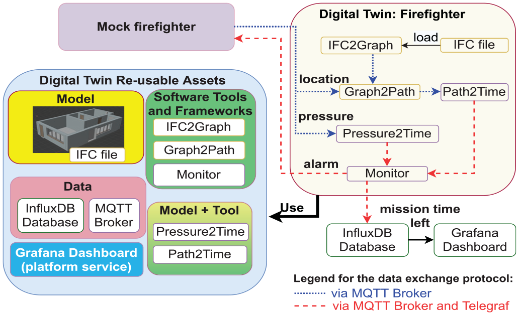
Re-usable assets included in the firefighter DT.
The 3D-building data specified as an Industry Foundation Classes (IFC)-file serve the role of model to the DT. Three tools are included in this DT.
Building Data Transformation (IFC2Graph), a tool that transforms building data from the IFC-file into a graph structure for navigation purposes. This tool is essential for creating an accurate and navigable representation of the building within the DT.
Route Determination (Graph2Path) determines the shortest path using the graph derived from building data. This tool plays a key role in the continuous route planning of the system.
Monitor is a runtime monitor for maintaining the safety of a firefighter. This monitor sends an alert if there is insufficient oxygen for the firefighter to safely exit a firefighting situation.
In certain cases, the models are integrated tightly into the tools and are published as one re-usable asset. Such integrations can be considered as model-tool pairs. There are two tools with integrated human physiological models in the firefighter DT. They are:
Air Consumption Calculation (Path2Time) is a tool that uses the shortest path information to calculate the amount of air consumed during navigation. This tool is vital for approximating the rate of oxygen depletion and managing the firefighters’ air supply.
Pressure to Time (Pressure2Time) uses the pressure sensor values to approximate the amount of time the air in the SCBA’s air cylinder will last.
Every asset in this list is reused for serving multiple firefighters with one DT for each firefighter. Multiple firefighters DTs can coexist at the same time on the platform, and their collected data can be shown in the same dashboard.
5. DT definition
Having defined the DT asset, we now turn to their composition into DTs. Indeed, for our purpose, a DT is mainly a (constrained) set of assets, called a DT configuration, connected to a physical system—the PT—using some services.
First, we investigate the constraints in the relation between assets to have a valid DT configuration. There is a dependency between the assets especially in the context of creating DTs (Figure 5): Only functions/tools can use models/data. A specific combination of these assets constitute a DT. We distinguish between the DT design (a set of assets) and its DT configuration.
A conceptual relationship between DT assets (Data, Model, Function, Tool) and DT configuration.
5.1. DT design
A DT design

We demand that a DT design has at least one tool.
5.2. DT configuration
The interconnections between assets, parameters (configurable runtime variables) of the assets need to be specified for each DT. This information becomes a part of the DT asset configuration (
The

Among all the configurations shown in Definition 2,
We denote an instance that stems from a design
Three situations demand adjustments to
A DT can also use external tools such as planning and optimisation. This is especially true in what-if analysis. If these tools are used exclusively within a DT, then, they can be considered as tools in the asset library. Otherwise, they are part of the infrastructure/external world.
5.3. Case studies
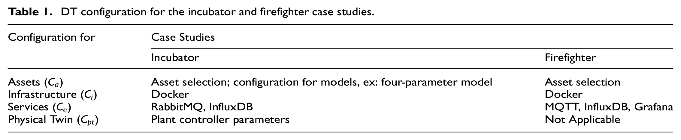
A mapping of
DT configuration for the incubator and firefighter case studies.
6. Phases in DT life cycle
A DT is a not a static structure—it transitions through a life cycle with different phases, and we consider it to be one of the main tasks of a DT platform to manage DTs in all these phases, as well as the transitions between these phases.
Two pioneering standards for DTs, namely, the ISO 23247:2021 Standard 65 (DT framework for manufacturing) and the IEC 63278-1:2023 Standard 42 (AAS for industrial applications which is based on the RAMI 4.0 model), use life cycle as a general principle for defining DTs. The former motivates the DT life cycle from the definition of product life cycle. However, such a definition states that DTs are more useful if the DTs in effect can be shared across the product life cycle, including design, planning, production, maintenance, and support. Similarly, the IEC 63278 standard motivates DT life cycle based on the life cycle of the physical asset that the digital representation is featuring, which can be done in a product or process. Digital twinning a product or a process require different (yet similar) life cycle phases, such as design, manufacturing, usage/maintenance, and end of life treatment for products, and design, implementation, operation/maintenance, and decommission for process. The life cycle phases so far are for DTs themselves. There is a need to translate these product life cycle phases onto DT platforms without the loss of conceptual and practical nuances. The rest of this section describes DT life cycle phases on DT platforms. The mapping of these phases to product life cycle phases is explained at the end of the section.
A DT life cycle on DT platforms consists of the create, execute, analyze, evolve, save, and terminate phases. The platform allows a user either to create a new DT or select an existing DT to engage with it in any of its phases. Thus, reuse is possible by reusing assets that existed before the DT is created, or reusing assets from prior runs and phases of the same DT. We next describe the phases on a conceptual level, and describe the used techniques in the case studies to illustrate them.
6.1. Create and execute phases
The create phase involves asset selection and specifying DT configuration. There is no creation phase at the time of DT reuse. The execute phase involves an automated execution of a DT based on its configuration.
6.2. Analyze and evolve phases
The analyze and evolve phases are concerned with monitoring and potential reconfiguration of a DT. Monitoring, at its most basic level, requires data gathering and storage, of the interaction between the PT and its environment, and among the PT’s assets. However, even for a simple system, such as the incubator, 66 monitoring requires that hidden quantities (that is, quantities for which we cannot obtain a sensor measurement directly) be estimated. This activity corresponds to analyze life cycle phase. Often these hidden quantities are represented by variables in various models used by the DT. The consequence is that estimates of these hidden quantities need to be stored in database, becoming then input to decision-making simulations, where all variables of the models need to be properly initialized. For more details, we refer the reader prior work. 51
Monitoring also informs the next life cycle stage of DT: the evolve stage. The evolve phase involves user/event-triggered reconfiguration of an instantiated DT. Note that the monitoring and planning steps make use of the other DT services.
6.3. Reconfiguration and consistency
The evolve phase requires reconfiguration of DTs. The aim of reconfiguration is to ensure consistency between DT and its PT, that is, the adequacy of the DT to mirror its PT, access its data, and enable the required analyses.
Reconfiguration may be triggered by different kinds of events, three of which we discussed above, they are specific to the system and, thus, reconfiguration procedures must be provided by the user. These procedures are highly application specific. The reconfiguration procedures must be able to access the current DT configuration and its assets. As the configuration is highly heterogeneous, the platform should offer a way for uniform access to it, that is, a representation mapping
6.4. Save and terminate phases
The save phase involves saving the state of DT to enable future recovery. If a DT is reused, there will be a temporal gap between creation and execution times of a DT. Thus, a need might arise for just-in-time (JIT) DT reconfiguration at the point of execution.
The terminate phase involves stopping the execution of the DT and releasing all the resources and connections mentioned in the DT configuration. It is also responsible for cleanup and correct shutdown of the PT (via its components), for example, for hardware-in-the-loop testing.
The create life cycle phase of DTaaS corresponds to creation of first prototype DT perhaps during the design phase. This create phase also corresponds to preparation of DT platform environment for DT execution. This DT will have to be executed to glean insights; such DT execution corresponds to execute life cycle phase via dedicated life cycle script/program. Depending on the results of execute life cycle phase, transition to other phases can happen. The save life cycle phase can be used to save DTs for reuse, that is future execution. The analyze and evolve phases together can help with DT management during the complete PT product life cycle. The terminate phase corresponds to termination of execution for a DT. This phase is specific to DT platforms and does not correspond to any PT life cycle phase.
6.5. Incubator
Figure 6 contains a mapping of different activities done for the incubator DT and the conceptual description of DT life cycle phases.
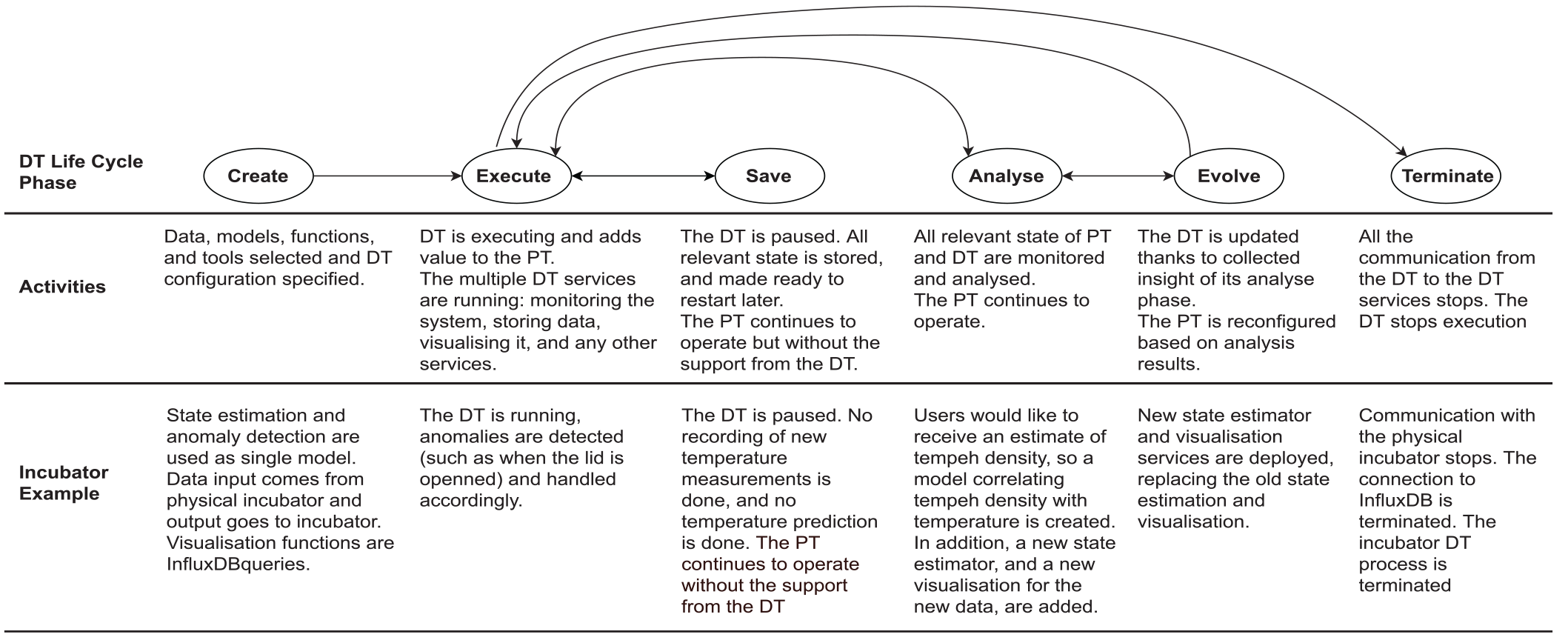
Mapping of the DT life cycle phases to the incubator use case. 66 The ODE acronym stands for ordinary differential equation.
In the create phase, state estimation and anomaly detection are combined into a single model. Data input from the physical incubator is processed, and the output is sent back to the incubator. Visualization functions are handled using InfluxDB queries.
During the execute phase, the DT runs, detecting and addressing anomalies, such as when the incubator lid is opened.
Transitioning to the save phase, the DT is paused. No new temperature measurements are recorded or predicted, but the PT continues to function independently of the DT.
In the analyze phase, users require an estimate of tempeh density. A model correlating tempeh density with temperature is created, along with a new state estimator and visualization for the new data.
In the evolve phase, new state estimation and visualization services are deployed, replacing the previous versions.
Finally, in the terminate phase, communication with the physical incubator ceases, the connection to InfluxDB is terminated, and the incubator DT process is concluded.
6.6. Firefighter
DTaaS platform’s management of firefighter DT is facilitated through a series of life cycle phases, detailed in the overview graphic in Figure 7.
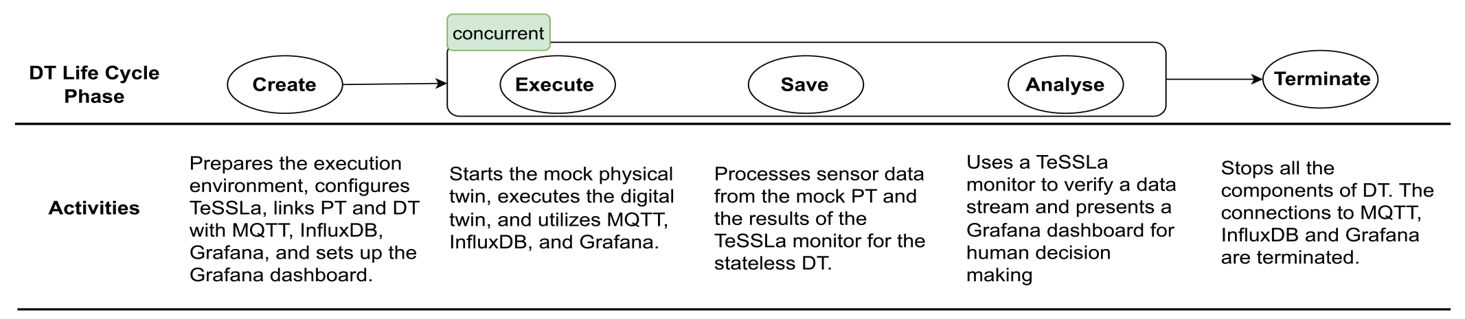
Mapping of the DT life cycle phases to the firefighter use case. 55
The DT assets are configured in create phase to create firefighter DT and to prepare the execution environment. The TeSSLa is configured, links between PT and DT are created using MQTT, InfluxDB, and Grafana dashboard is setup. Execute phase activates mock PT and DT. DT now employs MQTT for data transmission, InfluxDB for storing data, Grafana for displaying real-time information. Save and analyze phases are run concurrently to execute phase. The system’s design ensures that the most recent data from mock PT is always available, with historical data primarily used for human decision-making. In analyze phase, the TeSSLa monitor continuously checks for oxygen levels and sends an alert when the level is too low. In essence, the possibilities for firefighters to escape are continuously analyzed using monitor. The results are streamed in real-time to Grafana dashboard. This concurrent activation of execution, save, and analysis phases makes DT responsive and effective. The process concludes with terminate phase in which all the executing DT assets are terminated, connections to MQTT, InfluxDB, and Grafana are closed, ensuring an orderly shutdown of DT operation.
Through these life cycle phases, DTaaS manages the complex operations involved in the firefighting scenario, ensuring efficient data handling and real-time analysis for decision-making.
7. System architecture
Having established the notions of DT assets, DT configuration, and DT life cycle phases, we now examine the requirements for a platform that uses these concepts to manage DTs, as well as describe the microservice-based software architecture underlying DTaaS that realizes these requirements.
7.1. Requirements
The HUBCAP project 68 promoted the collaborative model-based engineering. One of the outcomes of the project is a collaborative sandbox platform in which the providers of the model authoring tools save their tools pre-packaged in VMs. The models are published as either public or private packages inside their workspaces. The users of tools instantiate VMs and work with their models. This experience has brought forth the need to support on-platform creation of DT assets. With the advances in virtualisation, it is now possible to support software tools inside containerised environments (Docker, Kubernetes etc.). In addition, there are cases where the generation of DT assets can be done impromptu. For instance, the safety monitoring use cases use runtime monitors like NuRV 69 which can generate the required model(s) for JIT execution of DTs.
The large-scale collaboration among partners creating DTs requires the ability to share re-usable assets and then help users discover the availability of existing assets. For example, the co-simulation-based DTs reuse Maestro tool. In addition, there is also significant reuse of functional mockup units (FMUs). Some of these FMUs are confidential. So there is a need to facilitate both the private and common spaces for DT assets. The DIGITbrain project 22 promoted the use of structured metadata for facilitating the discoverability of DT assets. It is important to note that the consolidation here refers more toward discoverability and less toward centralisation. As long as the assets are discoverable and integrable into DTs at execution time, their storage location is irrelevant. Such a decentralized storage of DT assets respects commercial advantages of asset owners and is not an impediment to DT execution. 70
The value of DTs is realized at execution time. This execution can either be manual or automated. It can also happen in centralized or distributed fashion. All these are possibilities DTs may take advantage of. For instance, incubator DT can be executed by users in their workspaces, or it can be executed as an automated service. It is also possible to package incubator DT into Helm Chart and execute the same on a Kubernetes cluster. Thus DT platforms need to support diverse execution environments for DTs.
The previous sections explain the advantage of re-usable DT assets and creation of DT from these assets using configuration. Thus support for configuration and reconfiguration is a vital feature on any DT platform. Some widely used DT platforms like Azure DT, Eclipse Ditto promote configurability as a means of managing DTs.
Monitoring and predictive maintenance are two prominent use cases for DTs. Monitoring of civil infrastructure such as bridges and power infrastructure such as wind turbine farms require DTs which are either 24 × 7 available or executable on-demand (CP-SENS project) 71 . For instance, a safety monitoring team might perform audit on the wind turbine farm and schedule the next audit after 12 months. If it is not desirable for the DT (as relevant to the audit scenario) to be run in the interim it is advantageous to save and re-instantiate the DT at the time of next audit. One of the key activities of a safety audit is to perform what-if scenario analysis to gauge the safety of the wind turbine farm under alternative weather conditions. The DT platforms must facilitate such a use case. One of the exemplar case studies developed on DTaaS is a fault injection based co-simulation. In this use case, faults are provided as DT configuration for a what-if scenario analysis.
Finally, users do have either direct or indirect interaction with DTs. The direct interaction needs to be facilitated via DT platform while the indirect interaction happens via services running on top of DTs. For example, the incubator DT integrates with InfluxDB on which pre-configured dashboards are loaded. The users can interact with these dashboards instead of directly interacting with incubator DT.
Summarized, the discussed user requirements are:
7.2. System components
Despite diverse requirements for different users, DTaaS presents a unified interface to the users. This unification is achieved by providing a gateway to consolidate the functionality provided by internal system components. Figure 8 shows the C4 system architecture 72 of DTaaS software platform. Users interact with the software via a web application. The gateway is a single point of entry for direct access to the platform services and is responsible for controlling user access to the containers. Each container contains a set of microservices. The term microservices shall be used henceforth to explain the system functionality implemented in C4 containers. The swapping of terms is to align with the architectural description of DT platforms in the existing literature. 73 The microservices are complementary and composable; they fulfill core requirements of the system. There are microservices for catering to store, explore, configure, execute, and scenario analysis requirements. Dedicated user workspaces enable authoring of DT assets. The microservices are packaged and deployed on Kubernetes cluster to take advantage of virtualisation, scalability, and service discovery.
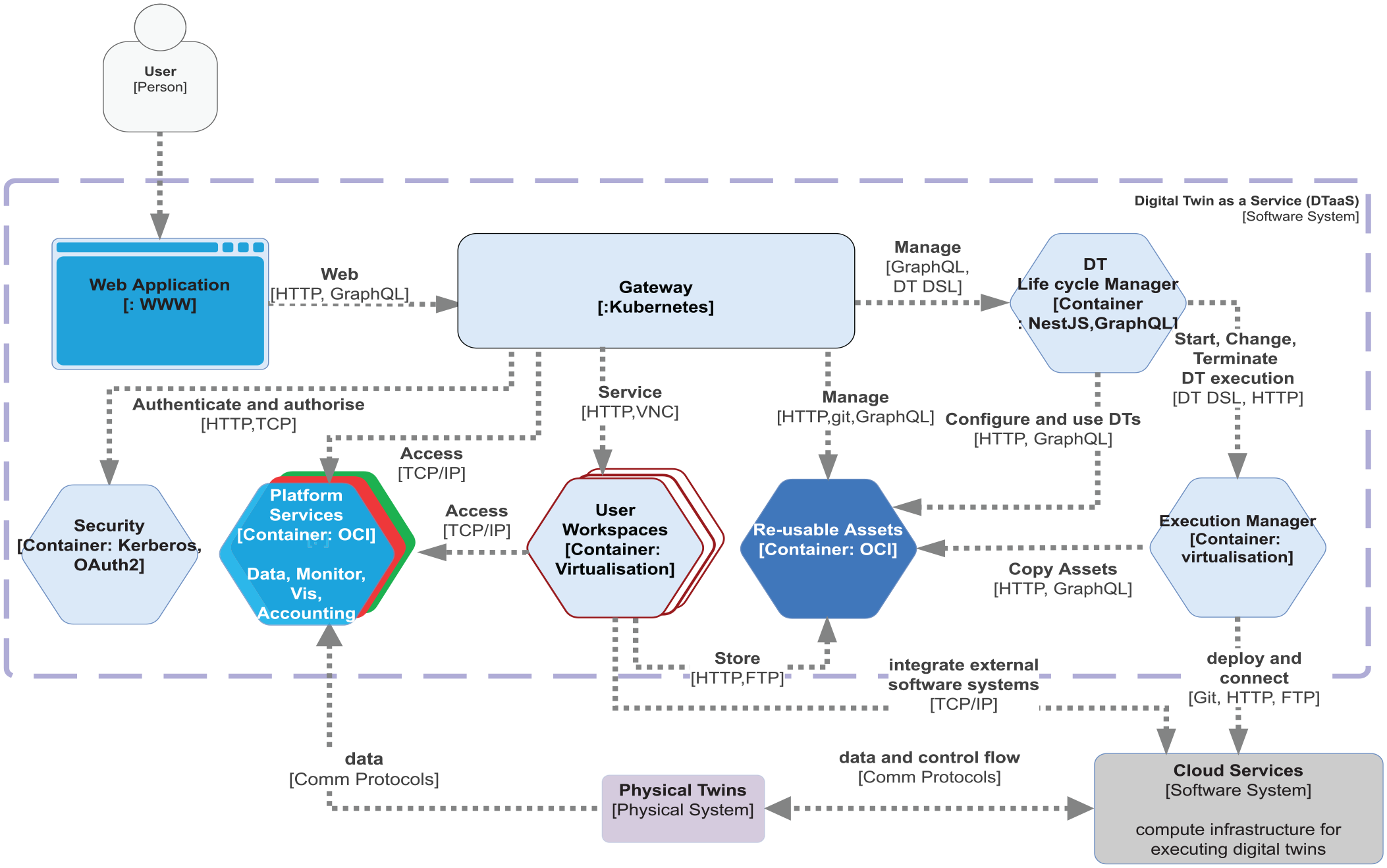
The software architecture of DTaaS platform. It is based on microservices architecture.
7.3. Microservices
The microservices illustrated in Figure 8 provide the bulk of the platform functionality. The security microservice implements role-based access control (RBAC) in the platform. The accounting microservice is responsible for keeping track of the platform, DT asset, and infrastructure usage. Any licensing, usage restrictions need to be enforced by the accounting microservice. Accounting is a pre-requisite to commercialisation of the platform. Owing to significant use of external infrastructure and resources via the platform, the accounting microservice needs to interface with accounting systems of the external services.
The data microservice is a front-end to all the databases integrated into the platform. A time-series database and a graph database are essential, from multiple reported cases in the state of the art. 1 These two databases store time-series data from PT, events on PT/DT, commands sent by DT to PT. It is possible to integrate dedicated Internet of Things (IoT) frameworks such as Eclipse Hono 37 into the data microservices. The PTs uses these databases even when their respective DTs are not in the execute phase.
The visualization microservice is again a front-end to visualization software that are supported inside the platform. Any visualization software running either on external systems or on client browsers do not need to interact with this microservice. They can directly use the data provided by the data microservice.
DTaaS is a collaborative platform. Users are able to have private and shared storage space to enable controlled sharing of either DT assets or DTs. The re-usable assets microservice (Asset MS) provides search, explore, and select functions over DT assets. Thus Asset MS should aid users in performing create-read-update-delete operations on the private and shared re-usable assets. Any ready to use DTs are also made available via the Asset MS.
The DT life cycle microservice assists users during all life phases of a DT. This microservice extensively uses other microservices to provide atomic operations at the level of DTs. This microservice acts as a controller to both the Asset MS and execution manager microservice (Exec MS).
The Exec MS is responsible for on-demand provisioning of virtual compute infrastructure. To make the platform scalable, the Exec MS must be capable of integrating with private and public cloud providers. Users operate with these isolated workspaces. The Exec MS receives DT configuration from DT life cycle MS and executes DT in isolated compute environment (ex: containers, VMs etc.). The Exec MS must interpret DT configuration specified in Definition 2. The required compute environment shall be provisioned as specified in
8. Platform implementation
The current implementation of DTaaS supports re-usable assets, DT life cycle, user workspaces and providing DTs as a service within the platform. Figure 9 shows the functioning system components providing the features mentioned here. There have been five releases of software so far and it is actively used by researchers and engineers from software engineering, electrical, civil, mechanical, and robotics domains. The entire DTaaS platform is available as two containerised packages. One is for the core platform and another is for the platform services. Users only need configure the OAuth, asset location, and network host/port information and the application becomes installable. There is also an DTaaS CLI python package 75 to perform user management of the platform.
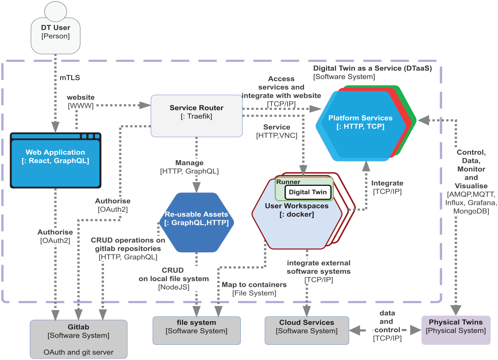
The current implementation of DTaaS platform. It supports composable DTs and provides integrated user workspaces. Re-usable assets microservice performs create, read, update and delete (CRUD) operations on DT assets.
The current security functionality is based on mutual Transport Layer Security (mTLS) and OAuth2 protocols. Users receive signed TLS certificates. The TLS certificate-based mutual TLS (mTLS) authentication and OAuth2 provides better security than the usual username and password combination. The mTLS authentication takes place between the users browser and the platform gateway. The gateway federates all the back-end services. The service discovery, load balancing, and health checks are carried by the service based on a dynamic reconfiguration mechanism. The OAuth2 integration is active for both the website and other services accessed via the service router.
Each DTaaS software installation comes with support for multiple platform services. These services are available to all users, DTs running inside the platform and the PTs linked to the DTs running within the platform. The DTs and PTs access the platform services using the standard network (TCP/IP) protocols. Thus any services supporting these protocols can be integrated with DTaaS. Five services have been integrated with the platform so far primarily to support the case studies already implemented on the platform. The integrated services provide communication, data storage, monitor, and visualization functionalities.
InfluxDB 76 time-series database and MongoDB 77 document database are also integrated into the platform. InfluxDB comes with data storage, and querying and visualization dashboards. The incubator case study uses this platform service for data storage and visualization. Users are permitted to share the dashboards. Thus DT experts can develop custom dashboards and share them with other users. MongoDB 77 Java Script Object Notation (JSON) document database is also part of DTaaS. If DTs or users wish to operate using data or asset configuration expressed in JSON, there is support for such usage.
There is support for AMQP, 78 MQTT, 79 and OPC-UA 80 protocol-based communication between PT and DT. These communication-related platform services can be used for bidirectional transfer of data and control commands between DT-PT pairs. Thirteen exemplar case studies have been made available publicly to showcase this support 81 out of which seven case studies have been summarized in this paper.
The Grafana 82 has been integrated as another platform service. This service is a de facto industry software to monitor, visualize, observe, and trace distributed systems. Given the need to support PTs deployed across multiple physical locations, software like Grafana is a good choice for monitoring and visualization. These services can be provided with data from PT in which case there is only PT monitoring and visualization. Digital Shadows provide one way communication from PT to DT. Even in this case, the Grafana and other platform services can be used to provide monitoring and visualization services. This same observation is valid even for DTs. A development version of the firefighter case study uses Grafana dashboard for monitoring and visualization purposes.
A re-usable assets microservice has been developed to provide access to re-usable DT assets to the platform users. This microservice uses GraphQL protocol for asset discovery and HTTP protocol for file transfer. The users can store both private DT assets and also get access to shared DT assets. Users can synchronize their private DT assets with external Git repositories. In addition, asset repository transparently gets mapped to user workspaces within which users can perform DT life cycle operations.
Many DTs do not provide API interfaces. Such a limitation reduces the integration possibilities of DTs with other DTs, platform services, and external software systems. In order to improve the integration possibilities, a runner microservice has been developed to create REST API wrappers around DTs. This microservice converts REST API calls to invoke life cycle scripts or any other scripts that can support direct operations on DTs. A user can create many DTs with or without runner integration. DTs with runner integration will be available as service to other users of DTaaS. Thus users have the flexibility to hide proprietary/private DTs and only provide access to them as services to other users. This feature gives rise to the possibility of creating collaborative DTs that are managed by multiple users.
A YAML Ain’t Markup Language (YAML) 83 -based configuration format is been defined to specify the DT configuration explained in DT Definition section. This configuration format will be used in future by the DT Exec MS. The users can fill the configuration template from their workspace or via web services exposed via the single page application.
All users have dedicated workspaces. The workspaces are implemented as docker containers running desktop Linux environment. These come with isolated docker containers having streaming desktop, VSCode, Jupyter notebooks, and remote terminal access.
A relational view of user workspace is provided in Figure 10. Each user workspace is private and is securely available via unified interface integrated into the single page web application. Users have access to re-usable DT assets. Users can install asset management tools of their own in the private workspace and use them to manage their DT assets. Users can also update the configuration of a DT and run life cycle scripts.
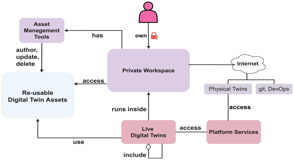
A relational view of the user workspace. The system components are all linked to the workspace and the DTs run inside the workspace. The DTs are also offered as services to internal and external users.
Users can run DTs within their workspace and make them accessible to other users. Any DT capable of providing services can be accessed by other users as services, thereby making DTs available as services.
Users can also permit remote access to live DTs via platform services. If a DT does not have an API interface, runner can be used to provide one which makes the DT becomes available as a service within and outside of user workspace. Using the service API interfaces of DTs with or without runner, users can treat live DTs as service components in their own software systems.
In addition, these workspaces have Internet access. Thus, the PT to DT bidirectional communication link is as simple as spawning required client-server communication protocol software. In addition, the platform services can always be used for bidirectional PT-DT communication. It is possible to restrict the DT-PT and DT-Internet communication. A suitable network firewall configuration can easily enforce the necessary restrictions. If users are well-versed in the software management processes, DevOps-related techniques can be used from within the workspaces.
8.1. Model management
It is important for DTs and DT platforms to support a combination of models produced using different mathematical paradigms. 85 DTs are heterogeneous of nature and thus when DTs are established for CPSs this support is paramount. In order to accommodate such integration, we make use of the FMI 86 standard but naturally there are other alternatives as well. The DTaaS already supports such diverse modeling paradigms. This support is made possible in four ways.
First is the availability of user workspaces in which models can be created and managed. Users are at liberty to use programming languages, engineering tools, and frameworks of their choice for model creation and management. The model generation tools such as Modelica, Gmsh 87 and Matlab can be installed and used for creation of models. Such tools can also help with the simulation of DTs in which these models are included. Thus models of different formats and representations are already supported inside the DTaaS. The exemplar case studies presented in Table 3 already have finite-element method (FEM), physics, ODE-based models published in FMUs, Modelica, and Python package representations. Other commercial partners have demonstrated proprietary System of Systems and FEM models as Matlab and Geo (by the Gmsh tool) files. These proprietary models could not be described in this paper due to commercial considerations.
Second is the JIT compilation of models. Sometimes users create models in one format (say in Modelica format) and compile them to another format (say FMUs) before the model is used inside a DT. Model compilation scripts used in the create DT life cycle phase (explained in Phases in DT Life Cycle) perform this kind of JIT compilation. The firefighter case study takes advantage of this technique to compile a Modelica representation into an FMU.
Third is the ability to use complementary and replaceable models for a single DT. The Re-usable Digital Twin Assets details different models in the incubator and the firefighter case studies. The selection of the available models for a DT is specified in the DT configuration.
Fourth is the dynamic, runtime integration of models into DTs. In this case, model integration and/or swapping happens during the evolve phase of a DT. This runtime change of DT models is controlled by DT configuration and data received by the DT at runtime. The Water tank model swap example (in Table 3) demonstrates dynamic swapping of FMUs.
While DTaaS allows the technical combination of different kind of models, it is in the responsibility of the DT creator to assure a semantically meaningful combination. Simulation granularity, especially notion of time, but also to the physical units, and so on has to be ensured when building a DT instance.
8.2. Comparison with existing platforms
Prior work5,16 provides qualitative comparison of DT platforms based on Structured data, Language specification, Co-simulation, Domain-specific, and Geospatial data DT frameworks and platforms. In order to objectively assess DTaaS proposed in this work, we take similar criteria to compare DTaaS with some existing frameworks and platforms that are used to realize DTs in the categories of Structured data, Language specification, and Co-simulation. The other two categories, namely, Domain-specific, and Geospatial data, are not considered since they are out of the scope of DTaaS platform.
Since some of the frameworks presented in previous surveys5,16 share similar characteristics, for example, AAS-based implementations (Eclipse BaSyX, SAP I4.0 AAS, NOVAAS, PYI40AAS, and AASX Package Explorer), IoT-based implementations (Eclipse Ditto, Azure DTs, and AWS IoT Greengrass), languages (DTDL, Eclipse Vorto, and Twined), and model-based implementations (INTO-CPS Co-simulation Framework and CPS-Twinning), a representative sample is taken with the most complete framework(s) per group based on the authors’ knowledge and experience with the tools and frameworks. Thus, the comparison considers Eclipse BaSyX and Eclipse Ditto in the Structured DT category, DTDL and Eclipse Vorto in the Language specification category, and INTO-CPS Co-simulation framework in the Co-simulation category. We compare the capabilities of DTaaS with the selected frameworks in a range of features, such as its capabilities regarding configuration files, which is relevant in frameworks like DTDL, 35 Eclipse Vorto, 88 and the AAS schema; its platform capabilities, which is relevant in frameworks like Eclipse BaSyX 40 and Eclipse Ditto; 38 its modeling and simulation capabilities, which is relevant in frameworks like the ones in the Structured DT and Co-simulation categories; and finally, its capabilities to integrate services both infrastructure- and DT optimisation-wise in comparison with the three categories mentioned above. Table 2 provides an overview of the comparison for the criteria Description of DTs and structures, Composition, DT-to-DT (DT-DT) relationships, Default bidirectional synchronization, Running simulators, Binding to infrastructure services, Binding to DT (optimisation) services, and Re-usability, inspired by the existing surveys on DT platforms/frameworks.5,16,90
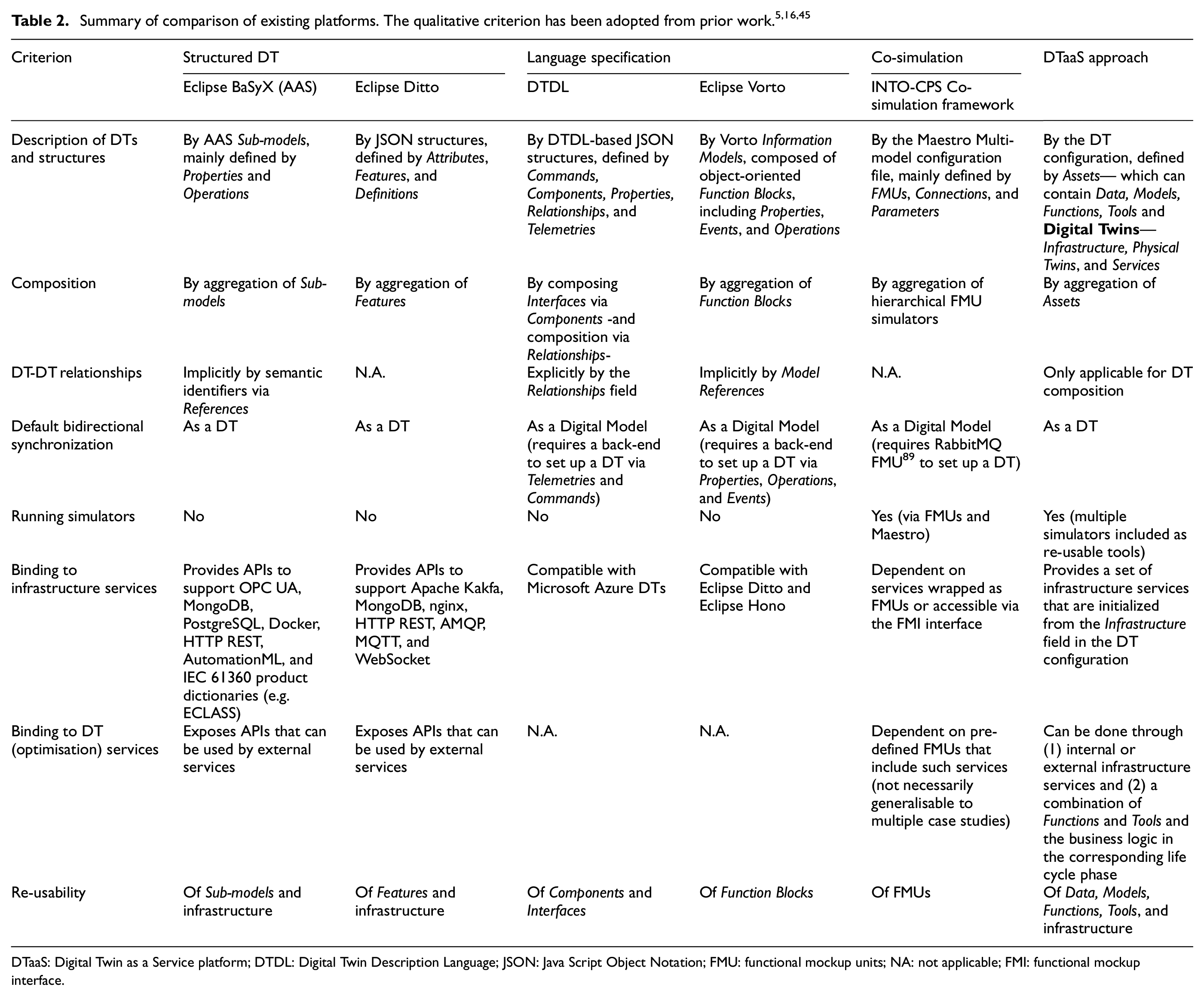
DTaaS: Digital Twin as a Service platform; DTDL: Digital Twin Description Language; JSON: Java Script Object Notation; FMU: functional mockup units; NA: not applicable; FMI: functional mockup interface.
In comparison to the selected platforms, as detailed in Table 2, DTaaS approach performs well in terms of the bidirectional communication capabilities, DT description, re-usability, binding to infrastructure services, and more importantly, integrating running simulators. Yet, it struggles with incorporating DT-to-DT relationships, especially for a more semantically accurate way to compose DTs, and with defining a more straightforward mechanism to set up and modularly attach DT (optimisation-wise) services. In addition, DTaaS supports hosting external third-party DT frameworks, such as the DT Manager, 45 where such an approach becomes a Tool in DTaaS context. This way, DTaaS can be used as a hub converging the realization of DTs where multiple tools, frameworks, and design paradigms co-exist.
9. Implementation of case studies
This section demonstrates use of DTaaS for working with DTs.
9.1. Incubator
The incubator was originally developed independently from DTaaS platform. This DT is an example of developing DTs outside of DTaaS and deploying them on it. The DT itself is re-usable in other DTs but does not have re-usable DT assets included in it.
Figure 11 shows the implementation of the incubator DT inside DTaaS. User instantiates an already available DT in the workspace as per the configuration. The DT connects with PT via RabbitMQ service and publishes time-series data to InfluxDB. A dashboard has been setup on InfluxDB to showcase analytical results produced by the DT. Please see prior work 91 for more explanation of the analytical results.
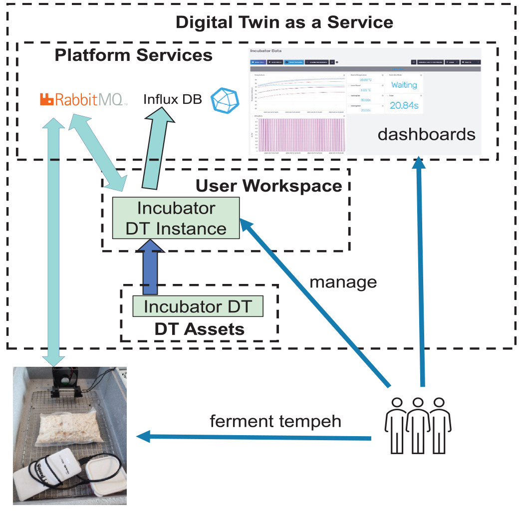
Incubator DT in DTaaS platform.
9.2. Firefighter
The firefighter DT case study implementation takes advantage of the DT concepts supported in DTaaS. The firefighter DT is put together from data, model, function, and tool assets as described in the Firefighter subsection. The DT uses MQTT, a lightweight messaging protocol, to handle data transmission. This broker acts as the central point for data exchange, ensuring soft real-time, and reliable communication among various system elements without the need for synchronization. The DT also uses data storage (InfluxDB) and visualization (Grafana) services integrated into the platform. Grafana provides a GUI for decision-making by the mission commander. A TeSSLa monitor is implemented for real-time monitoring of both the time needed to leave the building and breathing time left in the SCBA. It alerts when pre-defined thresholds are reached. The Telegraf-TeSSLa-connector 92 integrates TeSSLa into the system.
Figure 12 provides an overview of the sequence of events, facilitating efficient data exchange, and integration of different components. There are two sequences, each of which calculates a time. A graph is generated once in IFC2Graph with the 3D building file, in which navigation then takes place. The Graph2Path uses the position of the mock firefighter to calculate the path to the next exit. This path is used in Path2Time to approximate the time required to leave the building along a given path. The reported pressure values of the mock firefighters SCBA are used in Pressure2Time to approximate the time for which oxygen is available. These two times are monitored continuously. If there is a risk of insufficient oxygen available to leave the building, the firefighter is warned.
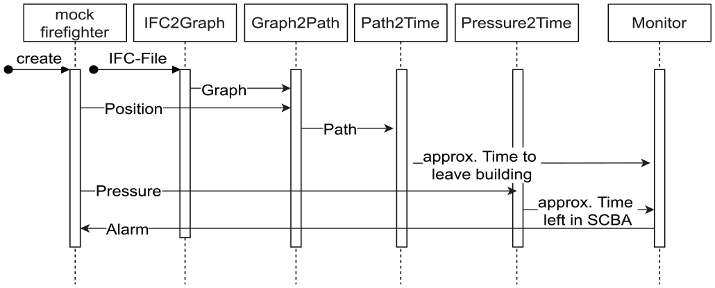
Sequence diagram of the DT for the rescue mission scenario.
The firefighter DT has been validated through simulations and feedback from firefighter technology providers involved in the O5G-N-IoT project as well as a few firefighters. These stakeholders have provided valuable insights into practical requirements and potential improvements for the system.
The firefighter DT is run in user workspace. DTaaS supports multiple firefighters DTs for each user while still maintaining the required isolation between all the active firefighter DTs. A collective monitoring results for different firefighter DTs can also be shown as one single visualization dashboard.
9.3. Other exemplar case studies
The existing users of DTaaS have developed multiple Digital Shadows and DTs to support their case studies. They have also generously contributed non-proprietary versions of their case studies as exemplars to other users of DTaaS. 81 Seven of these exemplars are summarized in Table 3. The exemplars come from diverse applications domains including Physics, Robotics, Food industry, and Water systems. The Desktop Robotti is a DT created for an autonomous agricultural vehicle; 93 the Flex-Cell Robots is a DT for flex-cell workstation. 94 The mass spring damper with runtime monitor demonstrates the use of NuRV 69 as a runtime verification (RV) and monitoring tool. This RV tool is integrated into the mass spring damper co-simulation DM. 95 There is no PT for this DM. However, this exemplar demonstrates use of two tools, namely NuRV and Maestro 58 for creating a DM. Such use of multiple models and tools ín one DT has been demonstrated again in other exemplars.
The implementation of seven more DT exemplar case studies inside DTaaS.
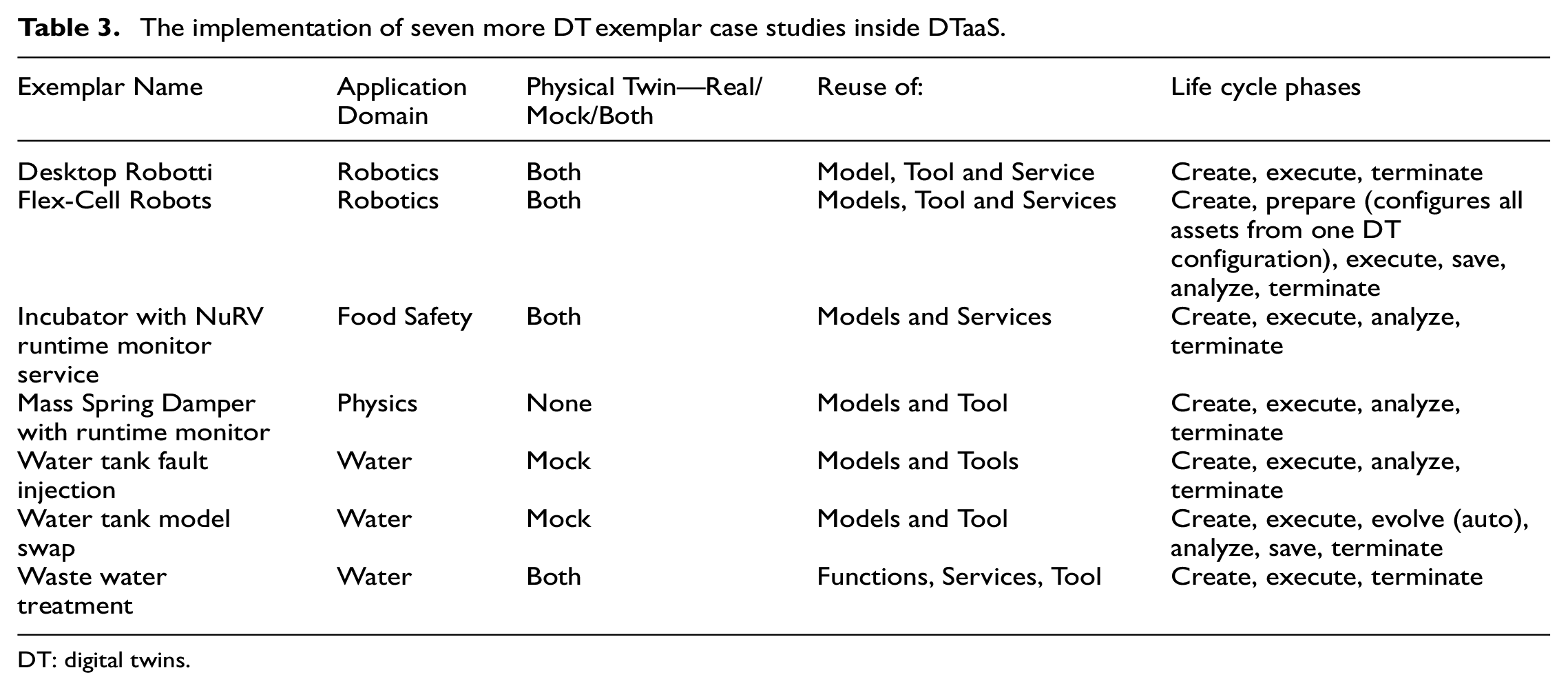
DT: digital twins.
The Water tank fault injection 96 and model swap 97 demonstrate the advantages of runtime fault injections and dynamic model swapping in DT.
There is a significant reuse of DT assets among the DTs created in different application domains. For example, the DT Robotti, Flex-Cell Robots, and Water tank model swap case studies use Maestro co-simulation engine as a DT tool asset. There is even reuse of models among the water tank model swap and water tank fault injection case studies. The incubator with NuRV runtime monitor service is a DT of incubator with integrated runtime monitoring service. This DT is an example of reusing one DT inside another DT. The Flex-Cell Robots is a pair of robots each of which have a unique DT which in turn are included in the Flex-Cell Robots DT. Thus it is possible to use more than one DT inside one DT and DTaaS supports such use cases as well.
Quite a few of these exemplars use the platform services integrated into DTaaS. The Desktop Robotti, Flex-Cell Robots, and incubator with NuRV monitor service use RabbitMQ service. The Flex-Cell Robots also uses MQTT service. The waste water treatment exemplar uses OPC-UA communication service. Thus the advantages of integrated platform services are evident in supporting the diverse case studies within DTaaS.
The Figure 13 illustrates the potential for re-usability of assets in DTs constructed using composition technique. The composition can be applied at either model/tool/service-level or at the DT level. There are two instances of a DT being composed in another DT. Such reuse is completely supported in DTaaS. Another advantage of this approach is to tailor the platform usability to the expertise of users. The expert users can create and manage all re-usable assets including DTs. Each DT is specified using one DT configuration stored in YAML format. The users of DT can create multiple instances of DT by having multiple configurations one for each DT instance. Thus users of DT need not concern themselves with the internal details of DT; they can just modify the DT configuration and instantiate a live DT which can then support the services built on top of it. These services can either be platform services or external services. The non-expert and decision makers can utilize the analytical results produced by the services. They do not need to even manage the DT itself; access to DT-supported services is sufficient.
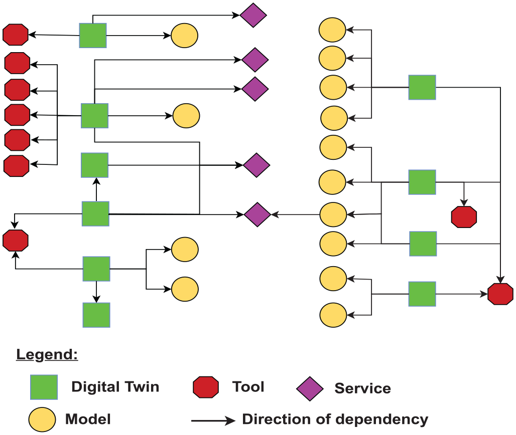
A dependency graph of all re-usable assets included in the case studies quoted in this paper. The dependency arrow goes from composing asset to composed asset.
10. Performance evaluation
10.1. Incubator
Multiple incubator DTs can be run by one user. Multiple users can run many incubators concurrently. The only limitation is on the capabilities of the underlying hardware to support the number of live incubators DTs. The incubator has a sensor that samples temperature values every 3 seconds. Thus the network delays and packet losses below 3 seconds are not observable.
10.2. Firefighter
In our performance evaluation, we conducted two experiments related to the firefighter use case to assess the system’s efficiency and robustness.
The first experiment involved comparing the performance of platform-hosted and remote MQTT servers. To compare, the system was configured to use either the integrated MQTT server or remote MQTT server and the communication times to and from a mock PT were measured with an additional MQTT subscriber. For each experiment 500 measurements were taken. The results are summarized in Table 4. The findings indicate that the integrated MQTT service significantly improves the system’s performance compared to the remote MQTT server.
Communication times for local and remote MQTT servers with and without network stress averaged over 500 measures each.
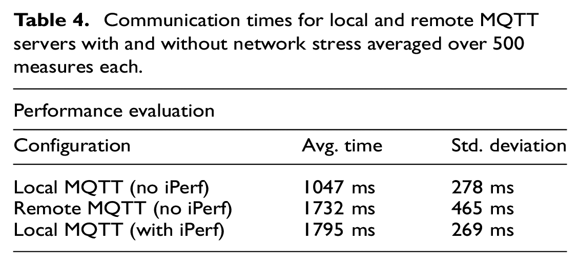
The second experiment focused on the impact of network stress on DTs running inside DTaaS. The network stack on the server hosting DTaaS has been kept busy by iPerf 98 throughput testing tool. The TCP client and server of the throughput test are on the same server. Thus the effective network bandwidth available to the DTs becomes reduced. The results are shown in Table 4. Despite the network stress, both the DT and DTaaS continued to perform as per the requirements, demonstrating its robustness under adverse conditions. The firefighter DT does not have safety and reliability system in place yet. We are currently working on a Fault Detection Identification and Recovery (FDIR) solution for some properties of the system. We intend to monitor the 5G configuration, possibly with some mesh network between the User Equipment (mobile devices) and the data rate usage of different data streams to detect faults, try to identify their causes and recover from them.
11. Discussion and future work
DTaaS is a platform for building, using, and sharing DTs. The reuse of DT assets is a guiding principle around which DTs are managed within DTaaS. This approach has been illustrated with two detailed case studies, and seven additional exemplar case studies. Significant progress has been made in the platform implementation, specifically in developing the re-usable assets microservice, enhancing scalability. The existing data, models, and tools have been shown to be re-usable, facilitating a smooth transition for users from their local development environments to DTaaS hosted on the cloud.
In addition, the DT configuration format has been defined and mapped to the two primary case studies, aiding new users in creating their own DTs and simplifying the adoption of DTaaS. A performance evaluation on the firefighter case study showcases DTaaS’s capability to handle PTs operating both on-premise and remotely, discusses the impact of network latency and validates the platform’s ability to execute multiple DTs concurrently. Five versions of DTaaS software have been released, and it is being actively used by researchers and commercial partners.
Ongoing work includes integrating semantic modules as a DTaaS platform service, enabling the interpretation of DTs as a knowledge graph for consistency checking and semantic querying. Future work will focus on extending the platform’s capabilities, enhancing the semantic module, and further validating DTaaS approach through additional case studies and user feedback.
12. Concluding remarks
There is a strong interest in the DT community to provide DTaaS to spread the user base of DTs. A typical DT life cycle on DTaaS involves create, execute, save, analyze, evolve, and terminate phases. Only software platforms developed with awareness of DT life cycle can aspire to fulfill DTaaS vision. Re-usability of DT assets, creation of meaningful DT configuration, scalable deployment is key challenges in the development of DTaaS platforms.
In this paper, we describe some nuances in DT configuration that is valid in the context of re-usable assets, shared infrastructure, and desired integration with external world. We believe that the ability to reuse DT assets on DTaaS will make it cheaper and easier to get started with DTs.
Footnotes
Acknowledgements
The authors thank in no particular order the successful discussions and feedback provided by the DIGITbrain technical coordination committee, Daniel Lehner, Mirgita Frasheri, Martin Sachenbacher, Gianmaria Bullegas and Omar Nachawati. They also thank in no particular order Artin Ghalamkary, Asger Breinholm, Astitva Sehgal, Cesar Vela, Emre Temel, Karsten Malle, Linda Nguyen, Mads Kelberg, Mathias Brændgaard, Nicklas Pedersen, Oliver Geneser, Omar Suleiman, and Phillip Jensen for contributing to the development of DTaaS platform. They thank Alberto Bonizzi, Alejandro Labarias, Henrik Ejersbo, Lucia Royo, Mirgita Frasheri, Morten Haahr Kristensen, and Valdemar Tang for generously contributing exemplar case studies.
Funding
This work has been partially supported by the EU Horizon 2020 projects DIGITbrain and HUBCAP and the Poul Due Jensen foundation, as well as the RCN grants PeTWIN (grant no. 294600), SIRIUS (grant no. 237898) and the German Federal Ministry for Economic Affairs and Climate Action, due to a resolution of the German Bundestag in the context of the project O5G-N-IoT.