
Abstract
The bending rigidity of laminated fabric was investigated considering the positions of the neutral axes in bending for components in addition to the tensile and in-plane compressive moduli of components. Theoretically derived equations were proposed to obtain the position of the neutral axis and to predict bending rigidity of laminated fabric. Eight face fabrics, ten adhesive interlinings and eighty laminated fabrics of those combinations were used for experimental samples. Tensile properties, bending rigidities and thicknesses of samples were measured and used to investigate the validity of the theory. The positions of the neutral axes for the face fabrics were obtained and they were not close to the centroid of the fabric. The calculated bending rigidities of laminated fabrics using the obtained position of neutral axes were more agreed with the experimental ones than the results by the method without considering the position of neutral axis. Therefore, it was found that the bending rigidity of laminated fabric can be predicted more precisely considering the position of neutral axis.
Clothing is made up of a number of subsidiary component fabrics. Among them, interlining is used to give garments a suitable appearance and stability. The interlining is one of the most important subsidiary materials, because of its role in the final appearance and function of the garment. An adhesive interlining using a thermoplastic resin is taken as a representative example. The properties of a fabric are considerably changed by laminating on an adhesive interlining. Therefore, quantifying the effects of adhesive interlining properties is desirable. In particular, the prediction of mechanical properties for laminated fabric bonded with adhesive interlining is of great interest.
There are some studies about prediction for mechanical properties of laminated fabric made of face fabric and adhesive interlining from the properties of components. Shishoo et al. 1 investigated the mechanical properties of laminated fabric with adhesive interlining and analyzed the relationships between the mechanical properties of face fabric and adhesive interlining statistically. According to the analyzed relationship, they derived simple regression equations for mechanical properties of laminated fabric. Fan et al. 2 investigated the relationship between the low-stress mechanical properties of fused composites and those of component fabrics. Based on these relationships, they suggested a set of equations to predict the low-stress mechanical properties of fused composites composed of fabric and fusible interlining fabrics. These studies proposed equations of prediction for the mechanical properties of laminated fabric based on statistical analysis. Although the prediction method by statistical analysis is a way of selecting adhesive interlining, a more precise prediction method is necessary because of its insufficient accuracy. Moreover, the relationship between the mechanical properties of adhesive interlining and laminated fabric is still unclear. If it becomes clear, more precise prediction will be possible.
Among the mechanical properties of laminated fabric, it is well-known that the bending rigidity of laminated fabric is much greater than the sum of bending rigidity for each component. Some researchers investigated the prediction of bending rigidity for laminated fabric through the theoretical approaches using the laminate theory of composite structures. Kanayama and Niwa
3,4
suggested prediction models for the bending rigidity of a composite based on the laminate theory considering the rigidity of adhesive. They verified those models with different types of interlinings. In the laminate theory, the increased amount of bending rigidity is explained as resulting from the strains by compression and extension at the original neutral axes of each component. When a fabric is bent, axial strain does not arise in the neutral axis. However, due to the laminating, strains by an extension and a compression of the original neutral axes will arise. The strains by these extensions and compression of the neutral axes form stress. The resultant force make additional moment so the bending rigidity of a laminated fabric will increase. If the elastic moduli in tensile and bending are the same, the bending rigidity of laminated fabric per unit breadth is given by Equation (1):
In Equation (1), it was assumed that the components were perfectly elastic continua. However, textile materials are not elastic continua, so the bending rigidity of laminate fabric has been separated into two parts, the contributions from the bending of the components and their extension and compression.
6
This is equivalent to differentiating between the tensile and bending moduli of the fabrics. Those differences have an effect on the bending rigidity of laminated fabric. If the elastic modulus in bending and tensile modulus of both fabrics are independent and the neutral axes in bending lie in the centroid of the cross-section, the bending rigidity of the laminated fabric is given by
However, some fabrics still showed relatively larger prediction errors than other fabrics. In this study, the reason for the errors was considered in detail. In Equation (2), the neutral axes of components were assumed to lie in the centroids. If the assumption is invalid, the bending rigidity of laminated fabric will be affected by it and the errors may be shown. Accordingly, it will be necessary to understand the effect of the position of neutral axes in components on the laminate bending rigidity.
In this study, a detailed bending theory of laminated fabric was proposed taking into account the position of neutral axes of fabrics in components. The theoretical equations of bending rigidity of laminated fabric were verified experimentally with samples that showed relatively large prediction errors by Equation (2).
Theoretical details
Let us consider a laminated fabric with component1 and component2, which neutral axes before bonding do not pass through the centroid. A cross-section through a laminated fabric, bent to a radius of curvature R, is shown in Figure 1. In Figure 1, component1 is inward and component2 is outward. η is the distance from the neutral surface in the laminated fabric. We take the origin at the neutral axis of the laminate. y
0 and y
1, y
2 are the coordinates of the surface and boundaries. y
1
n
and y
2
n
are the coordinates of the original neutral axes of the components. Because the strain of each component is proportional to the distance from the origin, component1 is compressed and component2 is extended while bending. It was assumed that a linear stress and strain relation is valid. Assuming the strains by extension and compression at the neutral axes of components are the mean strains in the component, a couple of forces will occur due to the stresses by the strains.
Bending of two-component laminate.
The compressive strain at the neutral axis of component1, ε
1, before bonding is given by
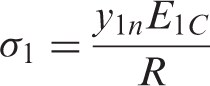
Then, the stress in component1, σ
1, is given by
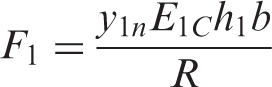
Similarly, the total force of component2, F
2, is
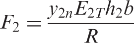
In experiments with fabrics, elastic modulus per breadth is usually used for convenience. Thus, specified moduli T
1
C
and T
2
T
are introduced as follows:

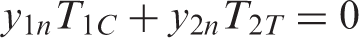
For no external axial force, the sum of the two resultant forces in Equations (5) and (6) should be zero:
When the distances from the bottom to the neutral axis of each component are denoted by y
1
n
0 and y
2
n
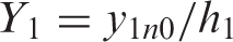
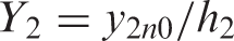
0, the relative positions Y
1 and Y
2 are expressed as follows:
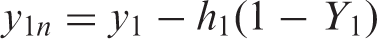
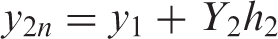
Then y
1
n
and y
2
n
are expressed as follows:
Substituting Equation (12) into (8), we can obtain

Then, y
1 is as follows:
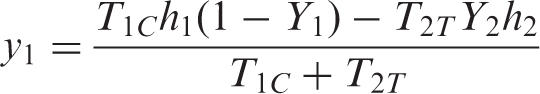
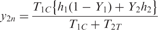
That gives the neutral axis of the laminate. Substituting Equation (14) into (12), y
2
n
can be obtained:
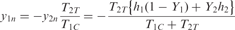
From Equation (8), we can obtain y
1
n
as follows:
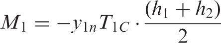
Because the two forces, Equations (5) and (6), are equal and opposite, they form a couple. By this assumption, the forces act at the centroid of components, and then the distance between the forces is (h
2 + h
1)/2. Accordingly, the couple per unit breadth and unit curvature, M
1 and M
2 is
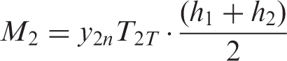
This is the contribution from the extension and compression of components. The bending rigidity of laminated fabric is given by the sum of these contributions and the contributions from the bending of the components.
Therefore, the bending rigidity of a laminated fabric can be expressed as follows:
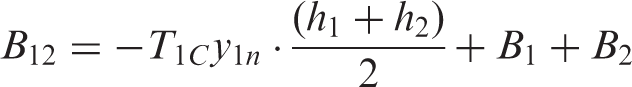
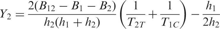
By substituting Equation (15) into (20), we can finally express the bending rigidity of the laminated fabric as follows:
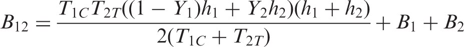
The bending rigidity of laminated fabric with two components, of which neutral axes do not exist on the centroids, can be predicted with Equation (21). However, among the parameters, T 1 C , Y 1 and Y 2 cannot be measured directly. 8 Therefore, a method to obtain those values was considered from the experiments under a specific assumption.
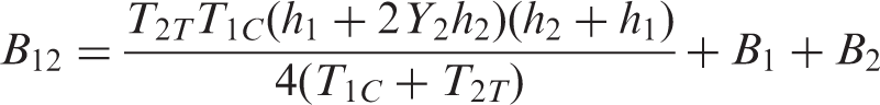
If Y
1 = 1/2, Equation (21) can be expressed as follows:
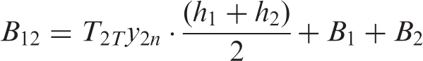
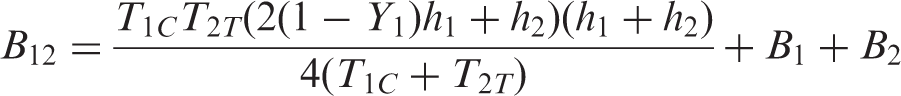
On the other hand, if Y
2 = 1/2, we have
Furthermore, if Y
1 = Y
2 = 1/2, we obtain Equation (23), which is the same as Equation (2):

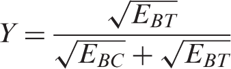
Let us consider the position of a neutral axis of a fabric theoretically. As has already been stated, the position of the neutral axis for a bent component cannot be measured experimentally. If EBT
and EBC
, which are the tensile and compressive moduli in bending, respectively, are known, the relative position, Y, of the neutral axis can be theoretically given by
Then the bending rigidity, B, of the fabric is expressed as follows:
8
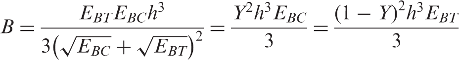
However, EBC , EBT and Y are unknown and cannot be measured directly. Therefore, an indirect approach was considered to obtain the necessary parameters with laminated fabrics in this study.
Firstly, let us consider Equation (22). If Y
1 = 1/2, the bending rigidity of laminated fabric can be predicted using Equation (22) with B
1, B
2, T
1
C
, T
2
T
, h
1, h
2 and Y
2. Here, B
1 and B
2 can be measured by a pure bending test. h
1 and h
2 can be measured. T
2
T
can be measured by a tensile test. T
1
C
is the apparent compressive modulus of component1 and there are some studies about measuring it.
9,10
However, those studies only suggested some possibilities of the measurement and a reliable method was not established. It is still difficult to measure it directly. Instead of a direct measuring method, an indirect method can be used. From Equation (23), T
1
C
can be expressed as Equation (26), and then T
1
C
can be obtained:

Using Equations (23) and (26), Kim et al. 7 predicted the bending rigidities of laminated fabrics with face fabrics and adhesive interlinings with an assumption that those neutral axes lie in those centroids. In the study, with T 1 C from two twill fabrics obtained using Equation (26), the predicted bending rigidities of laminated fabrics with adhesive interlinings showed good agreement with experimental ones. Thus, the assumption that the neutral axes of the twill face fabrics pass through the centroid was verified, and thus the T 1 C can be used in Equation (22) as well.
If T
1
C
is obtained, Y
2 can be obtained with the following equation:
Therefore, when the neutral axis of component1 is assumed to lie in the centroid, the bending rigidity of the laminated fabric with component2, for which the neutral axis is unknown, can be predicted using Equation (22), with T 1 C , h 1 and B 1 of component1 and T 2 T , h 2, B 2 and Y 2 of component2 obtained by Equation (27).
Let us consider Equation (22’). Equation (22’) can be applied to a reverse bending of Equation (22), in which component1 is outward and component2 is inward in bending. In Equation (22), it will be necessary to obtain T2C of component2, which the neutral axis does not lie in the centroid. However, the measuring method of T 2 C for component2 has not been reported yet. To verify the prediction of laminated fabric in the case of Equation (22’), further study on the obtaining method of obtaining T 2 C in the case that the neutral axis does not exist in the centroid will be necessary in the future.
In summary, the bending rigidity of laminated fabric can be predicted with four moduli (TT , T C, EBT and EBC ) or the relative position of neutral axis, Y instead of EBT and EBC , for component fabrics by the proposed method. For the reverse direction bending, due to the different neutral axis on the bending direction, the other relative position of the neutral axis Y’ will be necessary.
Experimental details
Experiments were carried out to verify the proposed equations for predicting the bending rigidity of laminated fabric from mechanical properties of face fabric and adhesive interlining before bonding. In this study, the bending rigidity of a laminated fabric was considered, except for the stiffness properties of a lining. In the usage of adhesive interlinings, an adhesive interlining is usually used on the inward side of clothing and the face fabric was on the outward side of the arc of bending. Thus, Equation (22) was verified by assuming component1 for an interlining and component2 for a face fabric.
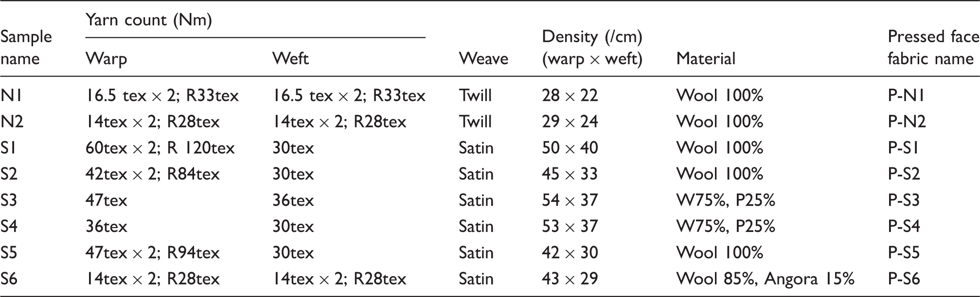
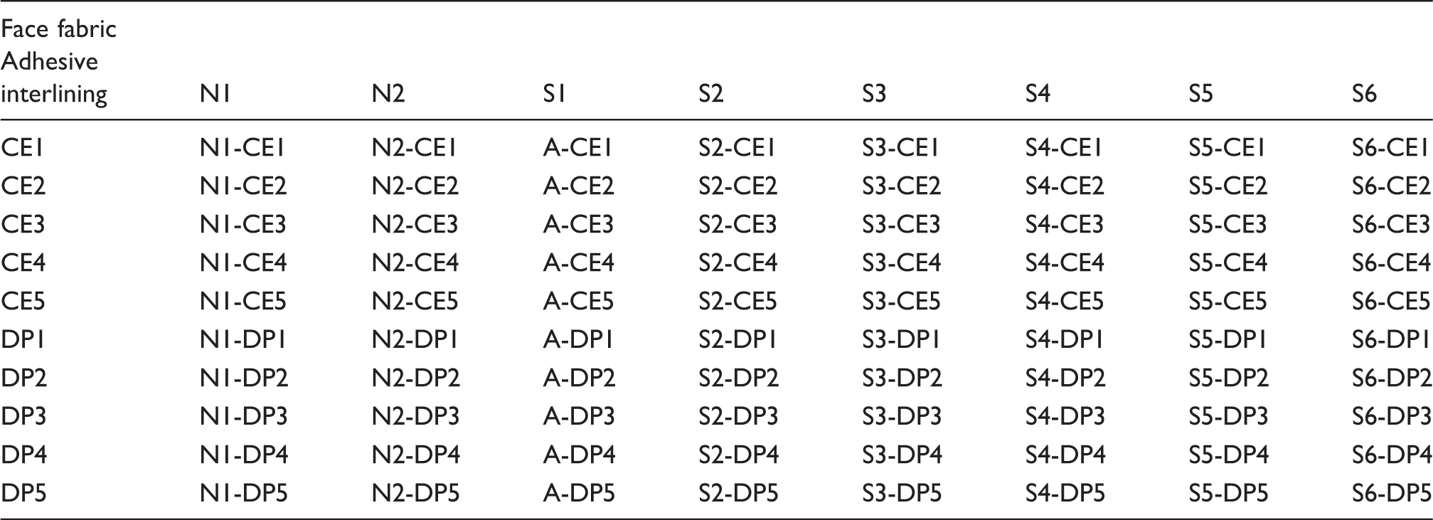
Face fabrics, adhesive interlinings and laminated fabrics with those combinations were prepared as experimental samples. Bending rigidities in warp and weft directions of all samples were measured using a KES-FB2 pure bending tester. 11 The thickness of each sample was measured using a KES-FB3 compression tester at 49 Pa load. The tensile properties of samples were measured by KES-FB1 tensile tester up to a maximum load of 490 cN/cm. The load at 0 to about 2.5% of elongation from the load-elongation curve was used to calculate T 2 T for each face fabric. 7 Every test was carried out under standard conditions (20 ± 1°C and 65 ± 5% relative humidity). All samples were preconditioned under these standard conditions for 24 hours. Every test was conducted on five samples and the results were averaged.
T 1C was calculated using Equation (26) with values obtained by the experiment using a combination of specific face fabric and interlining. Then Y 2 values of face fabrics were calculated using Equation (27). Using the Y 2 values, the bending rigidities of other laminated fabrics bonded with the face fabrics and different interlinings were predicted using Equation (22). Those results were compared with experimental data.
Specifications of the face fabrics
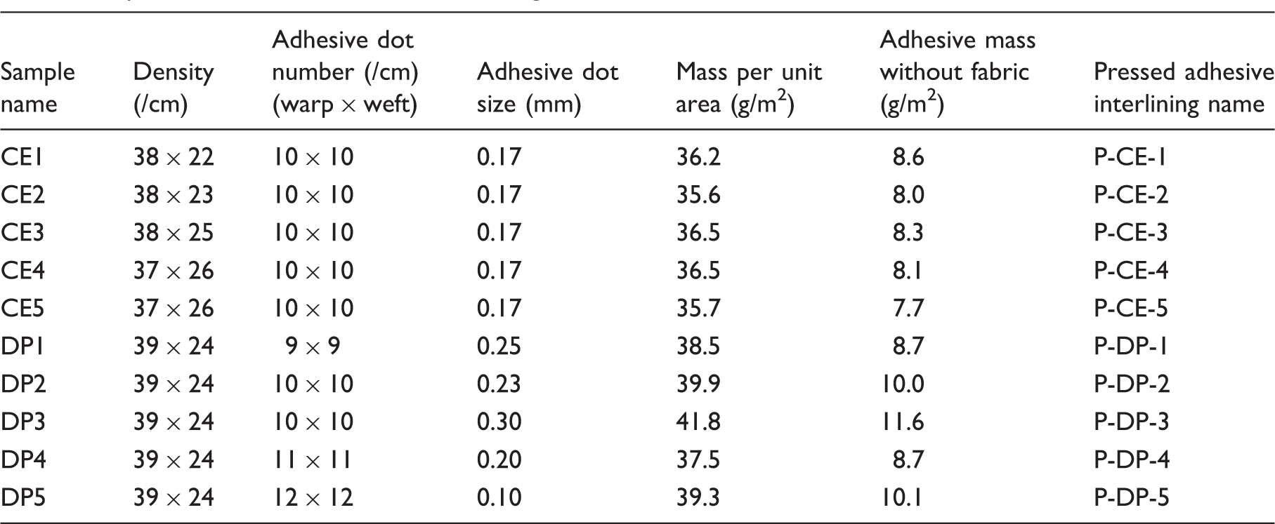
Specifications of the adhesive interlinings
Combinations of face fabric and adhesive interlining
The mechanical properties of component fabrics were changed after the pressing procedure for laminating and the changes of the mechanical properties for laminated fabrics must be considered when predicting the bending rigidity of laminated fabrics. 5 Therefore, samples pressed alone under the same press conditions of laminating and those mechanical properties were measured. The manufacturing method is as follows. Face fabric samples were pressed under the same conditions as bonding interlining. To press the adhesive interlining, polytetrafluoroethylene (PTFE) film (NITTO, No. 900, 0.05 mm × 300 mm) was prepared. Adhesive interlinings were bonded to PTFE films and PTFE films were removed from the adhesive interlining. Those samples were referred to as ‘pressed samples’. Face fabric and adhesive interlining were referred to as ‘pressed face fabric' and ‘pressed adhesive interlining'. The conditions for manufacturing the pressed samples were the same as for bonding interlining.
Results and discussion
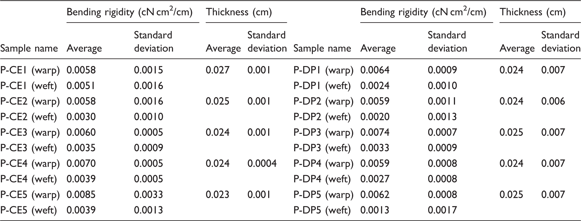
Bending rigidities and thicknesses of pressed interlinings
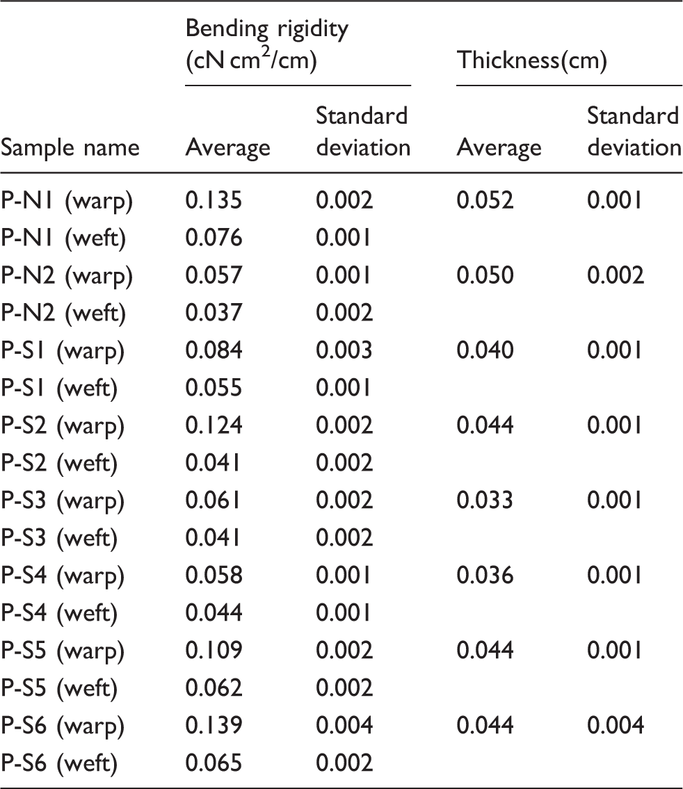
Bending rigidities and thicknesses of pressed interlinings
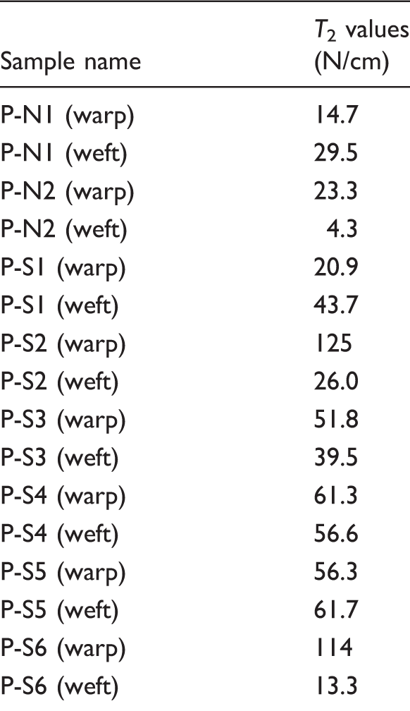
T 2values of pressed face fabrics
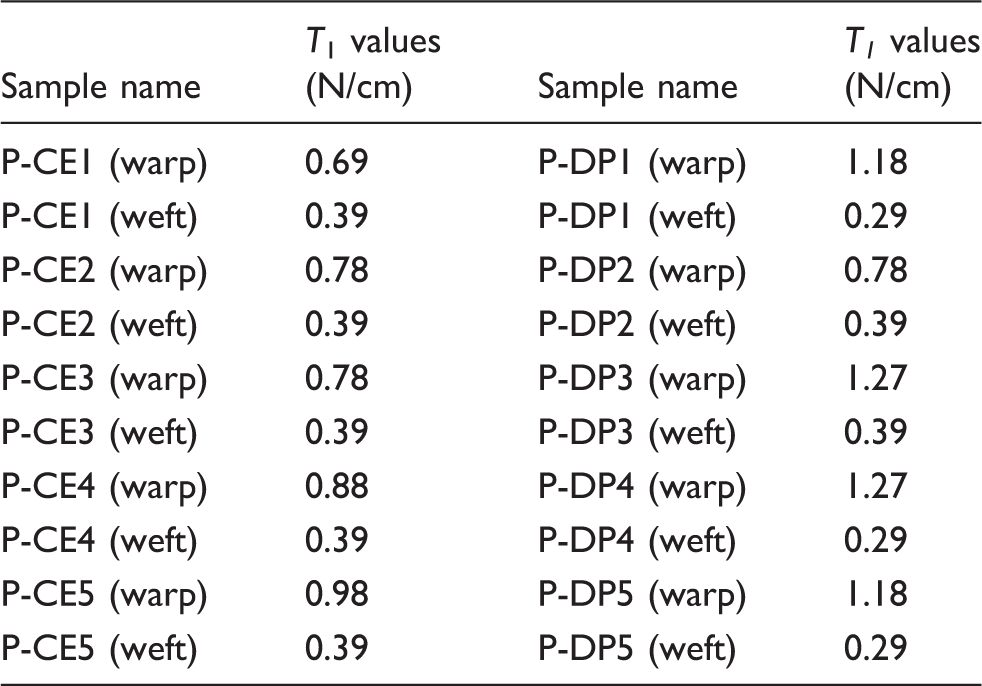
Average T 1 values of pressed interlinings from the face fabric, N1and N2
To predict the bending rigidity of laminated fabric with a face fabric for which the neutral axis does not pass through the centroid, obtaining Y
2 of the face fabric is necessary. With the obtained bending rigidity, thickness and tensile and compressive moduli, Y
2 values of the face fabrics were calculated by Equation (27); the averages for all samples are shown in Figure 2. Y
2 values of the face fabrics were similar for different adhesive interlinings. Thus, it was verified that the position of the neutral axis for the face fabric can be obtained by using Equation (27). As shown in Figure 2, the averages of Y
2 for all samples were close to 1. If Y
2 is close to 0.5, it means that EB
C
and EB
T
are almost the same. In that case, the predicted results will be similar to the results given by Equation (2). On the other hand, if Y
2 is close to 1, it means that EB
C
and EB
T
are very different. In that case, the neutral axis of the face fabric is close to the top of face fabric. Therefore, it was confirmed that the neutral axes of the face fabrics (S1–6), which showed large prediction errors using Equation (2), do not lie close to the centroid.
Averages of Y
2 values of face fabrics for different adhesive interlinings and Y
2 values from laminated fabric combinations of face fabrics and CE4 interlining.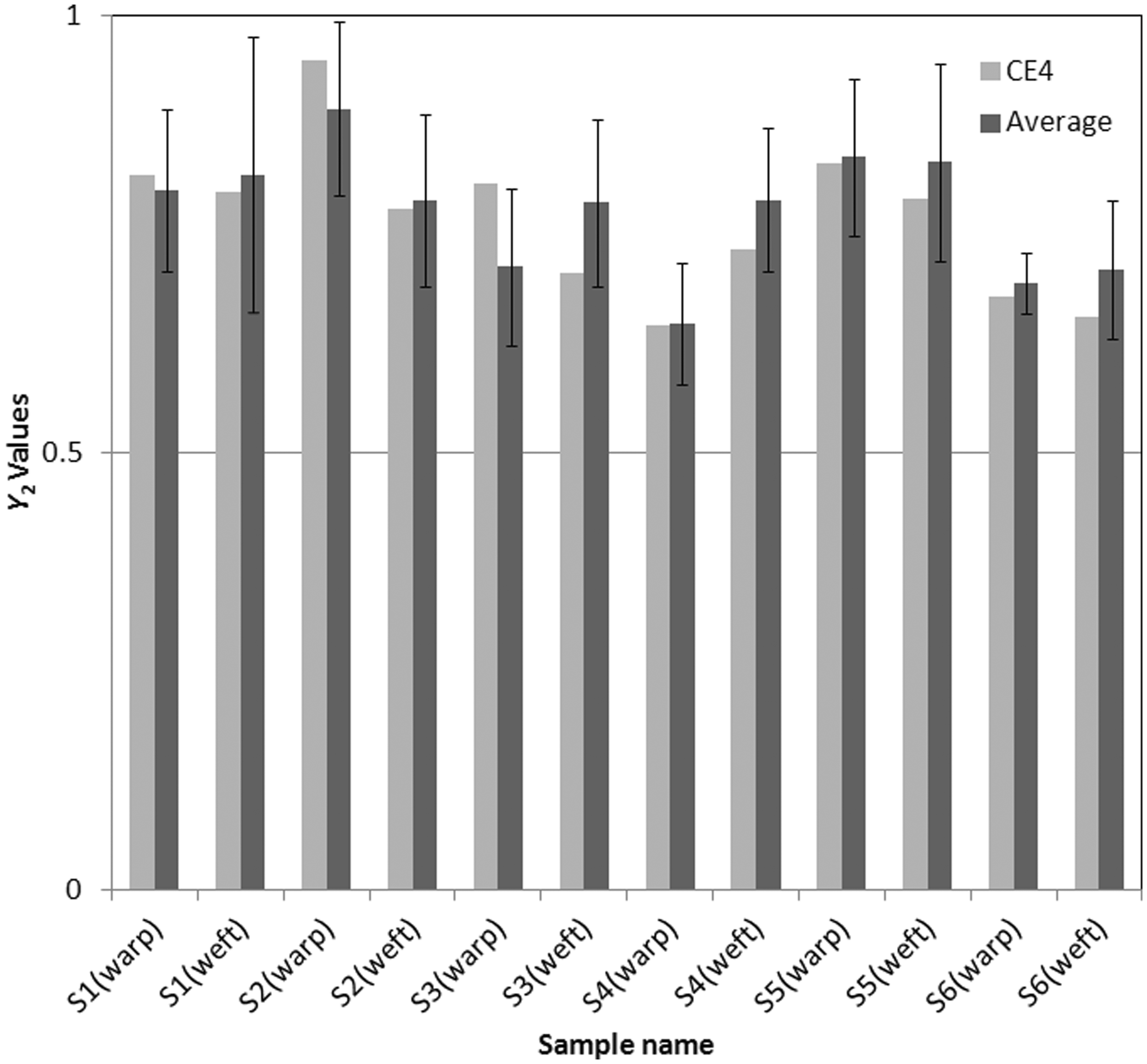
Although the Y 2 values of the face fabrics were similar for different adhesive interlinings, some variations were still shown between samples. This will be due to the permeation of the adhesive agent on face fabric and the non-linear properties of fabrics. However, the variations were not so large that the values can be acceptable.
If the predicted bending rigidities of laminated fabric with the obtained Y
2 values agreed with the experimental ones, it means that the obtained Y
2 values are reasonably valid and can be used to predict the bending rigidity of laminated fabric with other combinations. Thus, the bending rigidities of the laminated fabrics with other interlinings were predicted with the obtained Y
2. Here, the Y
2 values of face fabric from the laminated fabric with CE4 interlining were used because those showed the closest values to the averages of the obtained Y
2 values as shown in Figure 2. Figure 3 shows the comparison of predicted and experimental bending rigidities for laminated fabrics using Y
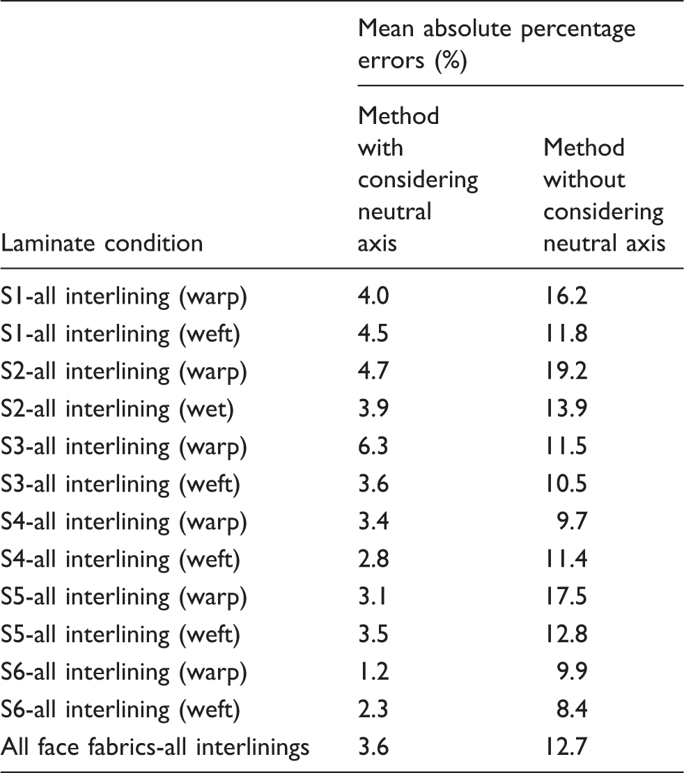
2. The predicted bending rigidities using Equation (2) are also shown in Figure 3 to confirm the effect of considering the position of the neutral axis. The MAPE from the results by the method with considering Y
2 and without considering Y
2 are shown in Table 8. As shown in Figure 3 and in its MAPE, the predicted bending rigidities with the obtained Y
2 showed closer agreement with the experimental data than those from the method without considering Y
2. The reason for the better agreement is the position of the neutral axes of the composites. Because a fabric is not elastic continua, the assumption that the neutral axis exists in the centroid is not always valid. These results showed that the bending rigidity of a laminated fabric was significantly influenced by the position. It is necessary to consider the position, especially for the bending rigidity of a laminated fabric. Thus, the predicted bending rigidities of laminated fabric considered Y
2 were in closer agreement with the experimental ones than the predicted ones without considering Y
2. It became clear that the bending rigidities of laminated fabric were able to be predicted more precisely with the method considering Y
2 than using method without considering it. The MAPE of all samples from the method considering Y
2 (3.6%) was less than for the method without considering Y
2 (12.7%). This was a valuable improvement, so it became clear that the position of the neutral axis is meaningful. Although the predicted bending rigidities of all samples showed better agreements, the MAPE is different depending on samples, as shown in Table 8. This may be due to the variation of Y
2. The predicted results are influenced by Y
2 directly, so the variation of Y
2 may cause the different MAPEs, depending on samples.
Predicted and experimental bending rigidity of the laminated fabrics by the method with and without considering the position of the neutral axis. Mean absolute percentage errors (MAPE) between predicted and experimental bending rigidity with and without considering the position of the neutral axis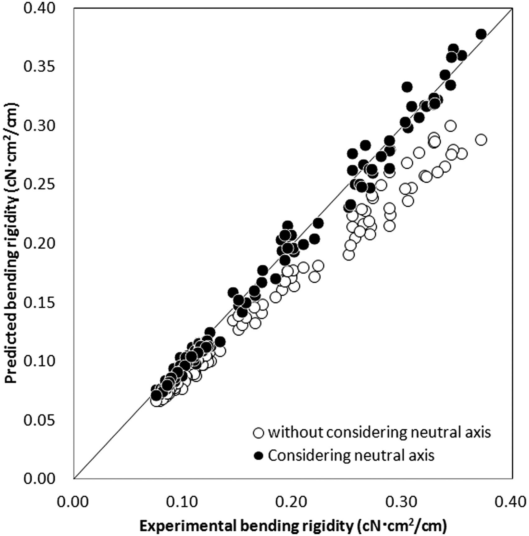
Therefore, it is certain that the bending rigidity of laminated fabric is affected by the position of the neutral axes of the components. This is equivalent to differentiating between the tensile and compressive moduli in the bending of the fabrics. The difference of the moduli was successfully considered in the proposed method. Thus, if the position of the neutral axis of a fabric is obtained, then the bending rigidity of the composite with the fabric and another adhesive interlining can be predicted. With this new method, the bending rigidity of a laminated fabric can be predicted more precisely.
In this study, satin fabrics were mainly used as samples, which show the largest prediction errors (over about MAPE 10%) by the method without considering the position of the neutral axis. However, it should be noted that not all satin fabric will show large prediction errors by the prediction method without considering the neutral axis. The tensile and in-plane compressive moduli of a fabric in bending may be affected by yarn properties in addition to the weave structure of a fabric. Therefore, the position of the neutral axis may vary in the case of fabric, even with the same satin structure.
Conclusion
A new theory of bending rigidity of laminated fabric was proposed. The position of the neutral axis in bending for face fabric is considered, in addition to the tensile and in-plane compressive moduli of components.
The proposed method was verified by calculating the bending rigidity of laminated fabrics, especially with the samples for which bending rigidity cannot be predicted precisely with the method without considering the position of the neutral axis. As a result, the relative position of the neutral axis of a face fabric was able to be obtained with the proposed method. The obtained neutral axis of the face fabric did not lie close to the centroid. Using the position of the neutral axis, the bending rigidity of the laminated fabric was predicted. The predicted bending rigidities showed closer agreement with the experimental data than those by the method without considering the position of the neutral axis.
Thus, in the proposed theory, it became clear that the obtained position of the neutral axis in a fabric is reasonably valid and it is able to predict the bending rigidity of laminated fabric more precisely with the position of the neutral axis.
Until now, the selection of adhesive interlining was carried out based on experiments and previous data. If the data concerning adhesive interlinings and face fabrics has been compiled once, the prediction of the performance of laminated fabrics made of different combinations will be possible. Therefore, this new method will help designers and manufacturers to select suitable adhesive interlinings for garments without extra cost and time.
Notations
adhesive interlining face fabric bending rigidity per unit breadth of component1 bending rigidity per unit breadth of component2 bending rigidity per unit breadth of laminated fabric with component1 and component2 thickness of component1 thickness of component2 radius of curvature distance from the neutral axis neutral axis of a laminated fabric coordinate of the bottom of laminated fabric coordinate of the border of components coordinate of the boundary at the top of laminated fabric apparent in-plane compressive modulus for longitudinal strain of the neutral axis for component1 apparent in-plane compressive modulus for longitudinal strain of the neutral axis for component2 apparent tensile modulus for longitudinal strain of the neutral axis for component1 apparent tensile modulus for longitudinal strain of the neutral axis for component2 compressive strain at the neutral axis of component1 stress in component1 total force of component1 total force of component2 couple per unit breadth and unit curvature of component1 couple per unit breadth and unit curvature of component2 elastic modulus of strain in tension of component1 elastic modulus of strain in compression of component1 elastic modulus of strain in tension of component2 elastic modulus of strain in bending of component2 distance from the bottom to the neutral axis of component1 distance from the bottom to the neutral axis of component2 relative position of the neutral axis of component1 relative position of the neutral axis of component2 tensile modulus of a fabric in-plane compressive modulus of a fabric breadth original neutral axis of component 1 original neutral axis of component 2 relative position of the neutral axis of a fabric
Footnotes
Acknowledgments
The authors would like to express their appreciation to NITTOBOSEKI CO., LTD for providing the experimental samples.
Funding
This work was supported by JSPS KAKENHI Grant number 24220012 and JSPS fellows, and Grant-in-Aid for Global COE Program by the Ministry of Education, Culture, Sports, Science, and Technology of Japan.