
Abstract
The development of an entirely polymer-based motion sensing glove with possible applications, for example, in physical rehabilitation is described. The importance of comfort for the wearer and the possibility to clean the glove in normal laundering processes were important aspects in the development. The glove is all textile and manufactured using materials and methods suitable for standard textile industry processes. For the first time, melt-spun piezoelectric poly(vinylidene fluoride) (PVDF) fibers with conductive cores were machine embroidered onto a textile glove to function as a sensor element. Electrodes and electrical interconnections were constituted by a screen printed conductive poly(3,4-ethylenedioxythiophene):poly(styrene sulfonate) (PEDOT:PSS) formulation. The screen printing of the interconnections was shown to be a reliable method for reproducible material deposition, resulting in an average surface resistivity value of 57 Ω/square. A repeated strain of 10% only influenced the resistance of the interconnections initially and to a very limited extent. The influence of washing on the electrical resistance of the printed interconnections was also studied; after 15 wash cycles the average surface resistivity was still below 500 Ω/square, which was deemed sufficient for the polymeric sensor system to remain functional during long-term use. Sensor data from the glove was also successfully used as input to a microcontroller running a robot gripper, in order to demonstrate its potential applications.
Keywords
At present, wearable sensors in textile garments and accessories are mainly represented by embedded conventional electronic devices, such as conducting metal wires, electronic sensors, integrated circuits, LEDs and batteries. The textile material does not in itself take part or constitute any functionality but is merely a substrate or vehicle. This approach leads to several problems, where lack of comfort, durability and user friendliness are perhaps the most severe. Metals are stiff materials and electronic devices usually have a rigid design; this makes them inappropriate for textile applications where significant stretching and bending commonly occur.1,2
An improved integration of smart functions into textile structures is especially relevant for the healthcare sector, where monitoring of body parameters such as respiration, heart activity, blood pressure and body movement are of particular interest. 3 As an example, motion sensitive gloves can be useful in combination with physical rehabilitation; the possibility to sense and register the wearer's movements can facilitate an objective assessment of the progress made after a specific training program.4,5 The positioning of the sensors and subsequent signal processing of such gloves were studied by for example Saggio, 6 whereas a more general review of glove-based systems was performed by Dipietro et al. 7 Still, less work is found regarding materials and processes enabling the smart systems to be fully integrated into the textile glove. Most of the sensor elements in the studies were composed of either commercial strain sensors or piezoresistive (passive) film sensors,4–6,8 the latter being any conductive material that changes its resistance when mechanically deformed.
Active, polymer-based fiber sensors have recently been realized by several research groups through melt spinning of the piezoelectric polymer poly(vinylidene fluoride) (PVDF).9–13 The piezoelectric properties entail that an electric potential is generated when the fibers are deformed, typically compressed or subjected to axial strain. The effect is activated by alignment of the dipole moment of the PVDF molecules, achieved by applying a high voltage through the material, i.e. polarization. 12 This, as well as recording the voltage signal, requires electrodes to be attached to the PVDF. Within our group, Lund et al. produced multifilament, bi-component fibers with PVDF as sheath and a conductive polymer composite (CPC) consisting of dispersed carbon black (CB) in polyethylene (PE) as core material, 13 forming a continuous inner electrode throughout the length of the fibers. A CPC was used as outer electrode and the fibers showed excellent sensing properties. For that investigation, the thermoplastic CPC was applied by fusing thick composite films to the sensor, a process which is not suitable for textile production. In another study by the same group, 11 the fibers were used as weft insertions and manually coated with a conductive silicone elastomer as the outer electrode and used as a heartbeat sensor. Again, the electrode material (Elastosil LR 3162 from Wacker Chemie AG) is not suitable for standard textile production, as it has a viscosity of 6.6 kPa s (shear rate 0.9 s−1).
In order to retain the flexibility and comfort of a textile with electronic properties, conductive materials are preferably integrated in the form of standard textile components, such as fibers, yarns, printing inks, or coatings. It is also advantageous to minimize the amounts of added components and confine the conductive material to the areas where it serves a function. For many knitted items, such as T-shirts and sweaters, screen printing is by far the most common technique to apply patterns.
A straightforward way to achieve prints with electrical conductivity is to add conductive material as the functional agent in the formulation.
A water-borne CPC for coating purposes, suitable for textile processing, was recently presented by us. 14 The conjugated polymer system poly(3,4-ethylenedioxythiophene):poly(styrene sulfonate) (PEDOT:PSS) was added to a textile coating formulation with ethylene glycol (EG) as a conductivity enhancer. The resulting organic textile coating was thin, flexible, and had a surface resistivity between 13 and 160 Ω/square, depending on its composition. The coatings were successfully used as the outer electrode material for piezoelectric PVDF fibers in a woven construction. The coating was applied using the pad-mangle method; a woven sensor fabric was dipped in a bath of PEDOT:PSS formulation. 15 The aim of the present study was to further this system by optimizing the PEDOT:PSS formulation for screen printing. The printed pattern should function both as an outer electrode for the piezoelectric yarn, and as electrical interconnections between the textile sensors and the controller electronics.
Generally, textile deposition of conductive materials, especially of conductive polymers such as PEDOT, often leads to poor durability to stretching and washing.16–19 Screen printed textile electronics was studied from a durability perspective by Yang et al. and Kazani et al.;20–23 both groups used commercially available silver pastes as the conductive layer in a printed multi-layer structure. The lowest surface resistivity achieved by these groups was 0.01 Ω/square and both remained well within the conductive range even after up to 10 wash cycles, although some loss in conductivity was noted in both studies. Since it is well-known that silver particles have detrimental environmental effects when released from textiles during washing and wear, 24 another aim of the present work was to present a textile application solely based on organic textile electronics.
The work included in this article addresses the comfort and durability aspects of wearable sensor systems, represented here by a completely textile motion sensing glove. The sensor system is constituted by a piezoelectric PVDF yarn and screen-printed conductive paths of a PEDOT:PSS formulation; in particular, the electrical conductivity of the screen-print as a function of cyclic strain and washing is presented. To demonstrate a potential application, sensor data from the glove was used as input to a microcontroller running a robot gripper, which in turn follows the movements of the wearer's fingers. The glove was produced using methods and materials suitable for industrial textile manufacturing processes.
Experimental details
Materials
Fabric
The plain warp-knitted substrate was New Monica from Sitip (Bergamo, Italy) with approximately 32 courses and wales per centimeter in each direction, a density of 220 g/m2 and composed of 78% Eclipse polyester (poly(ethylene terephthalate) (PET)) fiber and 22% elastane fibers. The substrate was chosen for its stability and reliable elasticity in all directions.
Piezoelectric bi-component fibers
Bi-component multifilament fibers were melt spun, as in earlier studies,11,13 using high density polyethylene (HDPE) (ASPUN 6835A, Dow, MI, USA) and CB (Ketjenblack EC-600 JD, Akzo-Nobel, Netherlands) as core material and PVDF (Kynar 705, Arkema, France) in the sheath. The yarn consisted of 24 filaments with an average diameter of 60 μm, where the core diameter was 24 μm.
Printed interconnections
For the printed electrodes and interconnections, the conductive material was PEDOT:PSS (Clevios™ PH 1000, Heraeus Clevios GmbH, Germany) with a solids content of 1.1 wt% (in H2O), a viscosity of 33 mPa s, and an average particle diameter of 30 nm. A commercial textile coating formulation (Performax® XPE1210, Lubrizol Advanced Materials Europe BVBA, Belgium) was used as the binder. The formulation was an aqueous dispersion of self-crosslinking acrylates with a solids content of 47.5 wt%. The rheology modifier used was a hydrophobically modified ethoxylated urethane (HEUR) (Borchi® Gel L75N, Borchers GmbH, Germany), with a solids content of approximately 48 wt%. Ethylene glycol (EG) (Sigma Aldrich, Germany) with a boiling point of 198℃ and a viscosity of 16 mPa s, was added as a conductivity enhancer and used as received. All data are according to the suppliers.
Sample preparation
Embroidered sensors
The multifilament piezoelectric fibers were twisted to a yarn with a DirecTwist 2D6 (AGTEKS, Turkey) in a z-twist structure with 150 twists/meter. The yarn was heat-set in an oven at 70℃ for one hour and then cooled in room temperature to achieve a relaxed and permanent state of the twisting. The yarn was used without any further treatments as the bobbin thread in an industrial sewing machine (Singer 591 D200G, UK). The thread tensions were adjusted so that the bobbin thread could lie as straight as possible when sewn/embroidered onto the substrate, but still securely fastened by the upper thread, which was a standard white polyester sewing thread.
The gloves were prepared in an order that would enable batch-wise industrial production. After tracing the glove pattern onto the knitted fabric, the sensors were positioned to stretch in response to finger bending, i.e. over the knuckles on the traced glove parts. The influence of varying the embroidery patterns on the signal output was included as an initial study where the piezoelectric yarn was embroidered in patterns according to Figure 1. The patterns were designed to give initial information regarding the influence of amount of yarn and sensor placement on the piezoelectric response: specifically whether the yarn should follow the longitudinal direction of stretch to as great extent as possible, as in (i), or whether it would be favorable to also collect forces acting in the transversal direction, as in (ii), or whether a pattern with a maximized total length of the yarn, as in (iii), would produce a stronger response.
Different patterns of the embroidered sensors.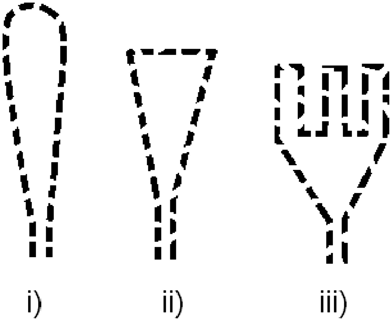
Poling
Polarization, or poling, of the piezoelectric yarns was carried out after embroidery. A corona poling method, previously thoroughly studied and proven sufficient to orient the dipoles, 11 was employed. The conductive cores of the embroidered yarns were contacted with silver paint and copper tape. The cores were connected to electrical ground and the sample placed inside a construction with needles pointing towards the fiber surfaces. The specimen, with the needle construction, was placed in an oven at 70℃. A voltage of 5–8 kV was applied to the needles for 50 minutes, the heat was turned off and the sample was allowed to cool to room temperature before removal of the voltage. This batch method is rather time consuming; a polarization method integrated with the fiber melt spinning process is under development within our group.
Printing
The components of the printing formulation were mixed with a stirrer (RW20, IKA®, Germany) for two minutes at 600 rpm, after which the formulations macroscopically appeared homogenous and stable. The mixture was characterized in a Bohlin CS melt rheometer with a cone-and-plate set-up using stress viscometry. According to Guion and Hood,
25
the significant shear rate for a printing formulation, independent of the settings of the screen printing process, is at 20 s−1, where the viscosity should be at approximately 10 Pa s for an optimal screen printing result. The slopes in Figure 2 show that this was achieved with the present formulation.
Shear viscosity of the formulation used for the printed interconnections (slopes of two independently run samples displayed).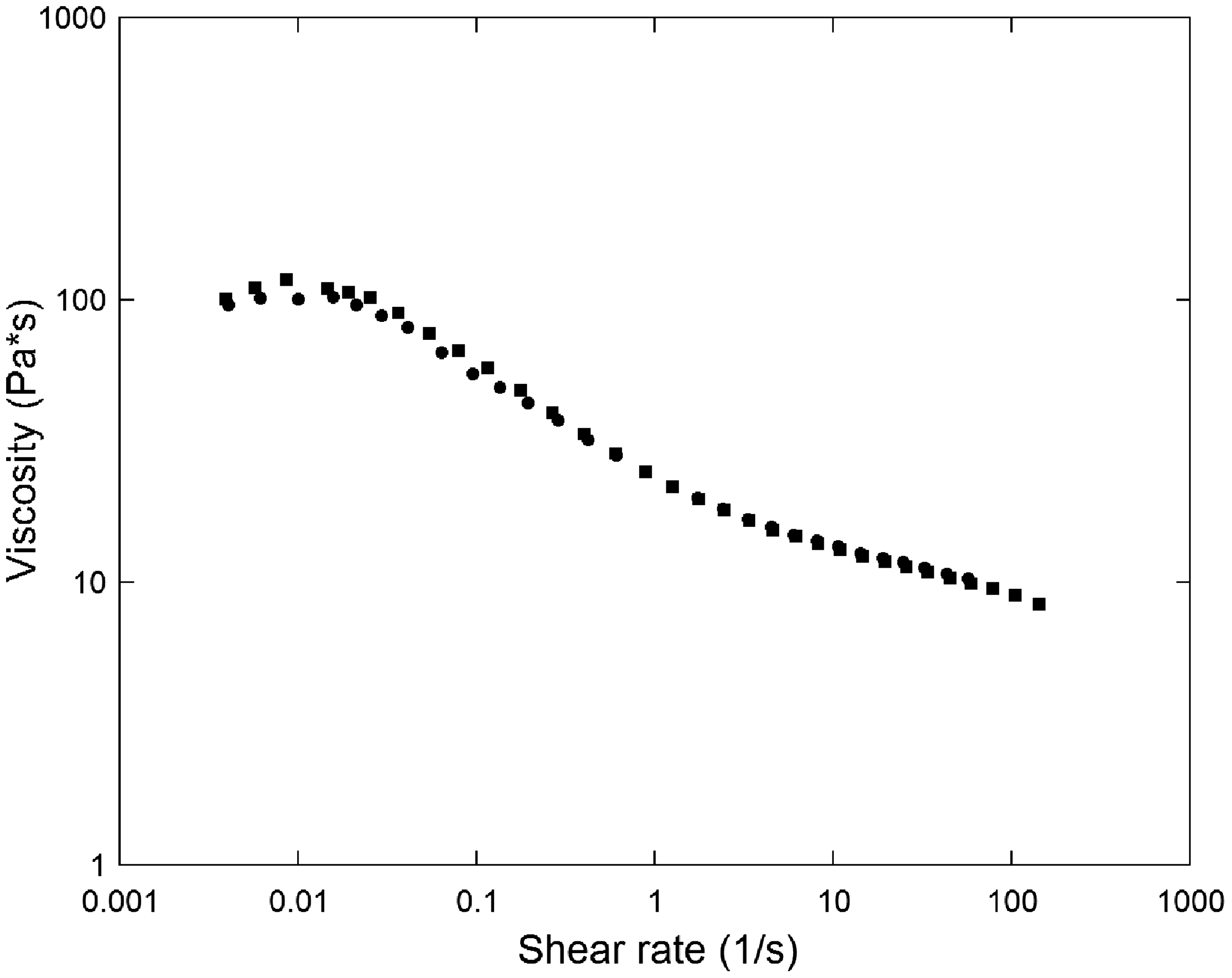
The printing was done on a magnetically driven laboratory printing table (Zimmer 1800 Frost, Austria) with a 120-mesh polyester screen and a rod with a diameter of 15 mm. The printing speed was 5 m/s. The rod made six passes on each sample.
The samples for the durability tests were printed in a pattern consisting of at least four rectangles of each size: 5 × 100 mm2, 10 × 100 mm2, 15 × 100 mm2, and 20 × 100 mm2, for every printing cycle. For the glove prototypes, the print pattern was individually adjusted to fit with the pattern of the embroidered piezoelectric sensors.
All samples were dried at 80℃ for 10 minutes (Labdryer LTE-S(M), Werner Mathis AG, Switzerland) and then left at room temperature for 24 hours. The purpose of the conditioning was to ensure maximum stability of the coating; in an optimized industrial process this step would be replaced by a quick heat treatment.
Assembly
The glove parts were cut out from the fabric and sewn together using an industrial sewing machine (Singer 591 D200G, UK) and a standard polyester sewing thread.
Electronics
The sensor glove output was connected by crocodile clips to a small amplifier circuit, including an RC-filter to minimize 50 Hz noise, constructed on a breadboard. The amplified signal was used to control a servo (S05NF STD from DAGU Electronic) attached to a robot gripper (Mk II Gripper, DAGU Electronic), via a microcontroller board (Arduino Uno from Arduino). The Arduino Uno board is based on the ATmega328, and was programmed with the Arduino software.
Test methods
Interconnection resistance
Electrical resistance measurements were performed using a multimeter (Fluke 8846A, USA) in a four-wire resistance mode and a four-point probe with the inner electrodes 20 mm apart; further details are published elsewhere. 14 A weight of 2.2 kg was placed on the probe, and the resistance values after one minute were used, according to standard CEI/IEC 93:1980. For the measurements of the interconnections from one end-point to the other, two-point measurements were employed and considered sufficient since the resistance of the whole length was significantly larger than any potential contact resistance.
Piezoelectric effect
The gloves were worn by a test subject and the conductive tracks were connected to an oscilloscope (Fluke Scopemeter 199C, USA) with an input impedance of 10 MΩ in parallel with 12 pF. In order to roughly evaluate the performance a simple test set-up using the trigger level of the oscilloscope was employed. While the test subject bent the fingers the trigger level was decreased until the oscilloscope gave a voltage signal. This gave a rough estimate of the electrical performance of the different sample gloves. The same gloves were tested repeated times during the same measurement and the tests were repeated several weeks after the first measurements, all giving similar results.
Cyclic strain testing
Screen printed samples in sizes of 15 × 150 mm2 were repeatedly stretched 10% in a tensile tester (Instron 4502, UK) with line clamps and a clamp distance of 100 mm, at a speed of 100 mm/min. The five samples were stretched for 10, 20, 30, 40, 50, and 100 cycles and the electrical resistance was measured after each interval.
Washability
The durability to laundering of the printed samples was studied according to standard EN ISO 6330:2012, method 6A, a 40℃ washing procedure with detergent and line drying, in a laboratory washing machine (Electrolux Wascator FOM71MP-Lab, Sweden). The washed samples were evaluated with electrical resistance measurements, as described above.
Results and discussion
Design of the sensor glove
The gloves were studied as a proof-of-concept, as illustrated in Figure 3, with the overall purpose of validating the electrical function of the textile approach. As such, the focus was to test whether the 100% polymer-based textile electronics remained true to their function. In order to verify this, it was considered sufficient to limit the amount of sensors to one per finger and the sensing confined to the movement of entire fingers, where the greatest strain in the glove occurs just over the knuckles. The concept was tested with the piezoelectric sensor yarn embroidered onto the glove and the interconnections printed according to the schematic drawing in Figure 3(iv)). This drawing shows the glove seen from above with the grey yarn sensor placed for the full bending of the index finger, with the printed interconnections leading down to the wrist.
Concept from bi-component fiber to sensing glove. (i) Cross-section of piezoelectric fiber, conductive core in black, PVDF in white. (ii) Schematic illustration of multifilament piezoelectric yarn. (iii) Embroidered sensor of piezoelectric yarn with placement of outer and inner (electrically connected to the conductive cores of the cut fiber ends) electrodes indicated. (iv) Schematic illustration of placement of sensor, electrodes, and interconnections on glove.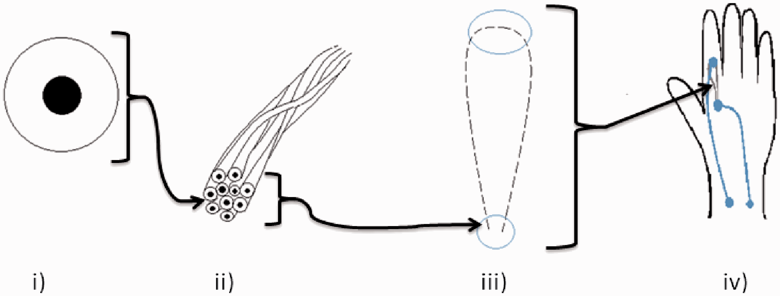
As the fiber cores constitute one electrode, a conductive coating will constitute the second electrode common for all fibers. During poling, polarization will occur radially causing the fibers to be sensitive to radial contraction or expansion, which typically occurs during stretch and release. For maintained effect, the coating constituting the outer electrode must be electrically separate from the fiber cores, as illustrated in the images of Figure 3(iii) and (iv).
The glove was designed to fit tightly onto the wearer's hand, in order to maximize the strain on the embroidered piezo yarn. Since the finger length and the hand width are highly individual, the test prototype was designed to fit the hand of one specific test subject. Due to the very stretchable fabric the prototype was however found to fit neatly on others with similar hand size.
Electrical resistance as function of geometry of interconnections
For obvious reasons, it was preferable that the printed interconnections were as narrow as possible on the glove. In order to characterize the printed interconnections separately, samples were prepared by screen printing geometrically defined areas of the interconnection material on the knitted fabric. As expected, the electrical resistance increased approximately linearly with decreasing width of the printed area, illustrated in Figure 4. The average surface resistivity for the prints independent of their widths was 56.7 Ω/square, with a standard deviation of 4.2 Ω/square. For this system, considering the possible variations due to processing parameters, this is a comparably small standard deviation. This indicated that the interconnections could be made rather fine without interfering with the sensing signal.
Resistance and corresponding surface resistivity of the printed samples of different widths, displaying power-law curve fit for resistance.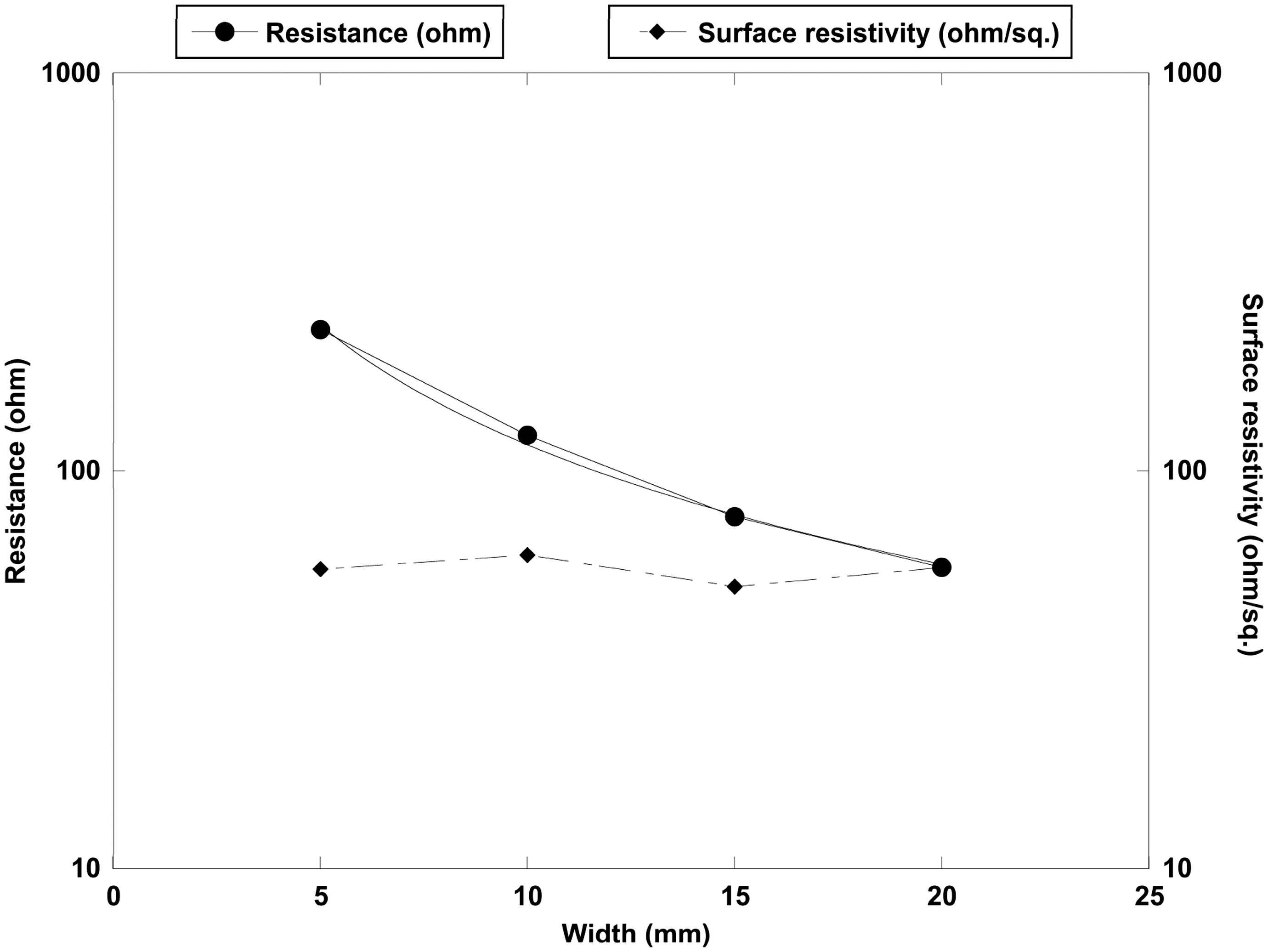
Testing the gloves
Trigger level and total interconnection resistance of gloves
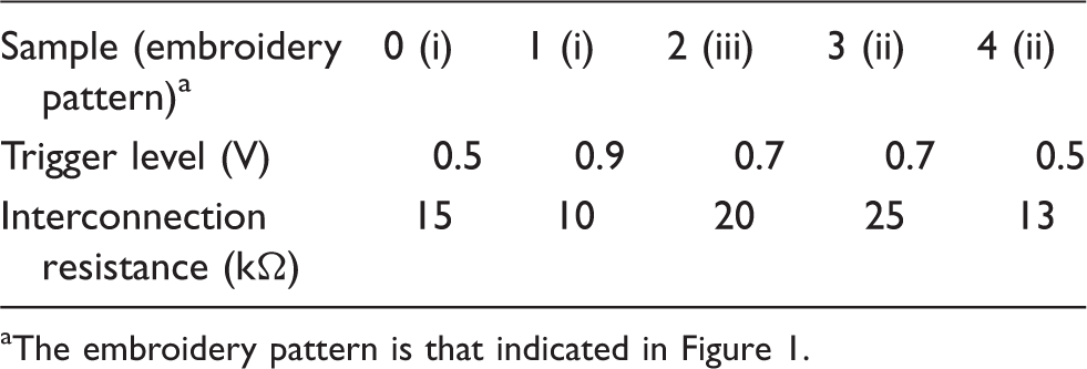
The embroidery pattern is that indicated in Figure 1.
The different patterns of the embroidered sensors, illustrated in Figure 1, did not significantly influence the results in this study. In terms of trigger level, from Table 1, the mean value of all samples put together, is between 0.6 and 0.7 V for all three patterns. In this study, the length (amount) and positioning of the embroidered sensors were only briefly studied but we would suggest more thorough studies of this, preferably with the yarn inserted in the knitted construction directly. A continuous poling process for the piezo yarn is also under development, which should enable that the same conditions are used for each batch of yarn and exclude the cumbersome individual poling procedure of each sensor.
The sensor glove was used to provide data input to control a robot gripper, utilizing the fact that the operations of stretching and releasing the piezoelectric fiber will both produce signals but with opposite polarities. In our setup (see Figure 5), the gripper closes when the wearer of the glove bends their index finger, and opens when the index finger is straightened.
Photographs illustrating the robot gripper following the movements of the glove.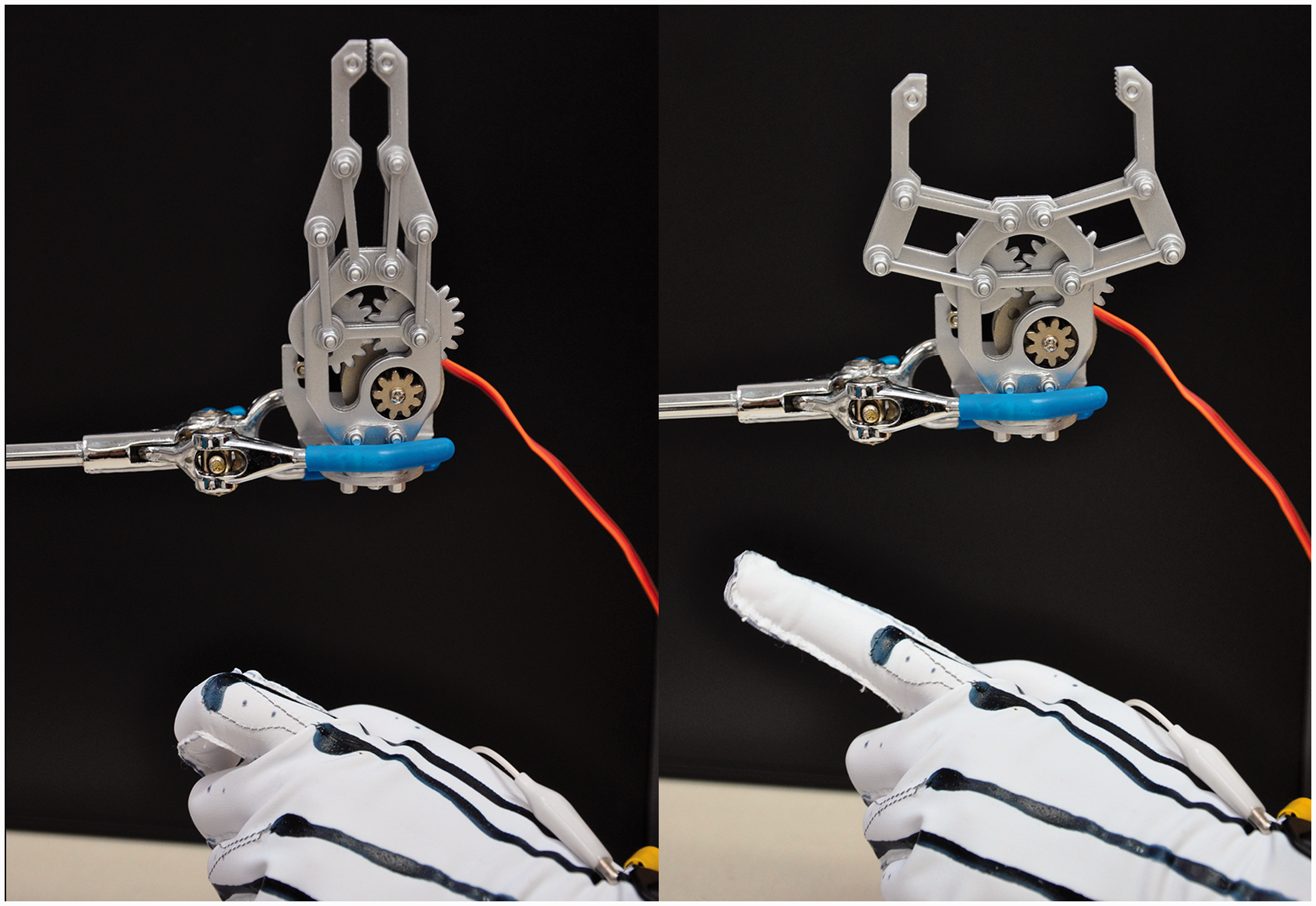
The robot gripper was controlled by a microcontroller situated on an Arduino board, to which the output signals from the piezoelectric fiber on the glove were connected via a high impedance buffer (Figure 6).
Schematic overview of the electronic circuit and a photograph of the set-up.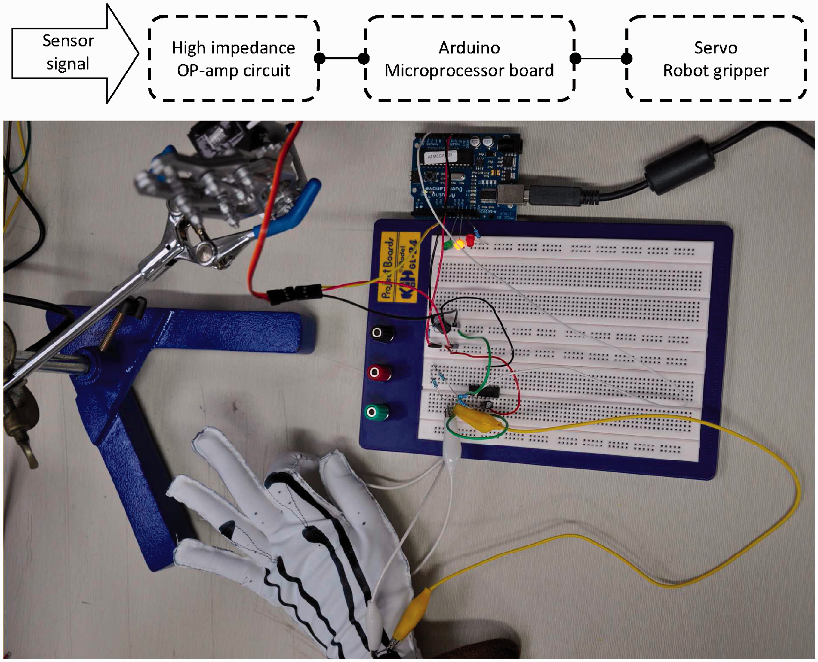
The buffer is constituted by an operational amplifier circuit, as shown in Figure 7. In this circuit, the gain (G) is given by:
Schematic of the high-impedance buffer and amplifier circuit.
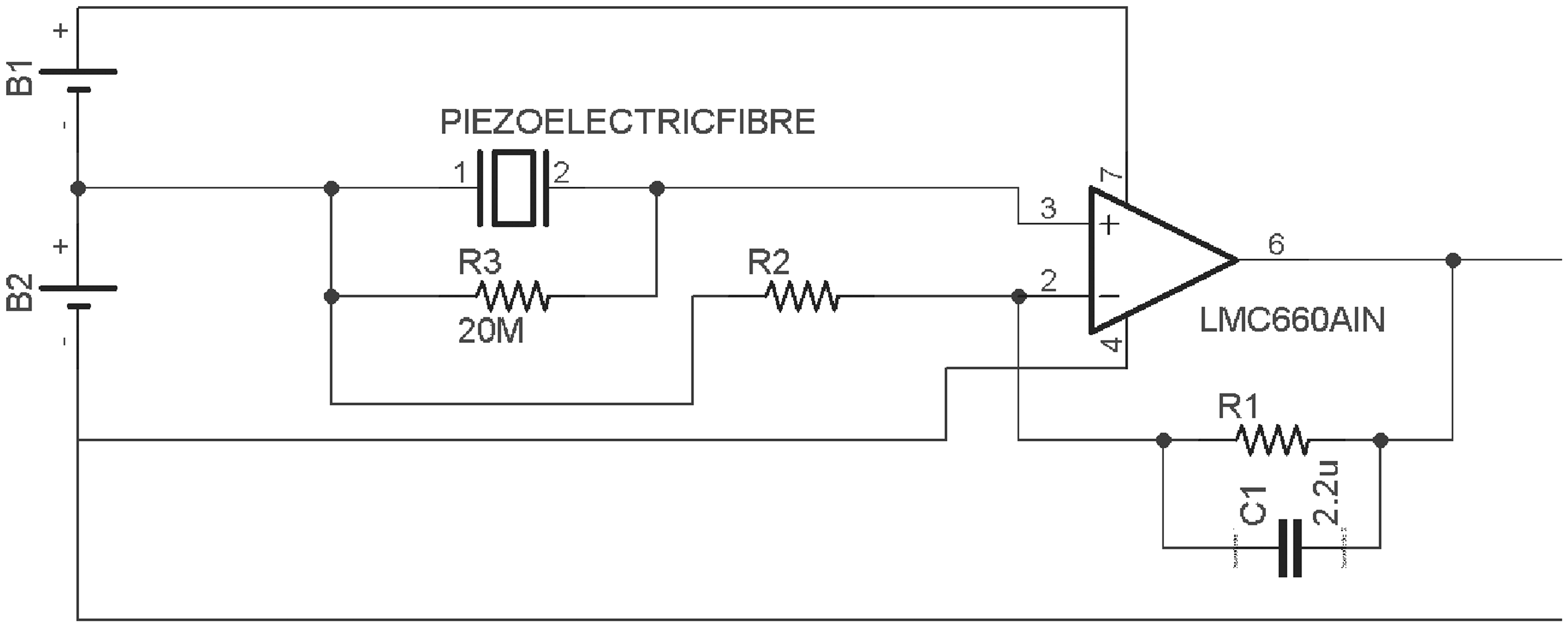
As the piezoelectric fibers are liable to produce a noisy signal with spikes, a FIR-filter was implemented in the software running the microprocessor.
Durability
Cyclic strain
Durability during repeated strain is a crucial factor for the interconnections on the knitted and highly elastic fabric. Figure 8 shows the impact of cyclic strain testing on the electrical resistance of the samples printed with a width of 15 mm. After the initial, small increase after 10–20 cycles of 10% strain the resistance value was stabilized. This indicates that the prints sustained the strain tests very well. The piezoelectric yarns themselves require only a small strain, of 0.07%, to produce an output of 4 V.
11
It would therefore be sufficient for that function if the electrodes were able to withstand an equally small strain. However, it must be anticipated that conductive prints can be subject to higher strains when placed on a tight-fitting glove, which was estimated to 10%. It would be highly interesting to further investigate the upper limit for strain tolerance, as well as studying creep and stress relaxation properties of this coating.
Resistance of printed samples subjected to repeated strain.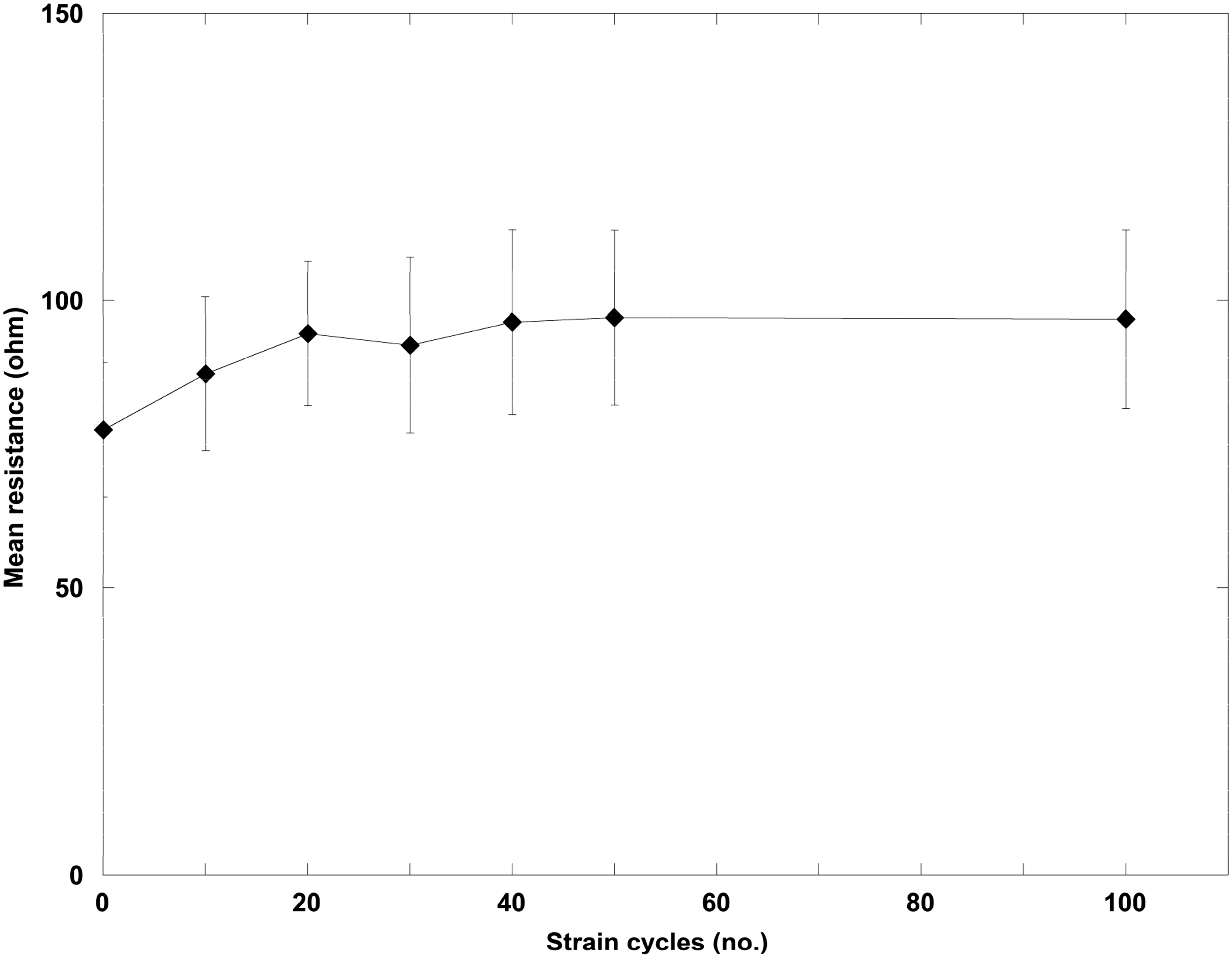
Washability
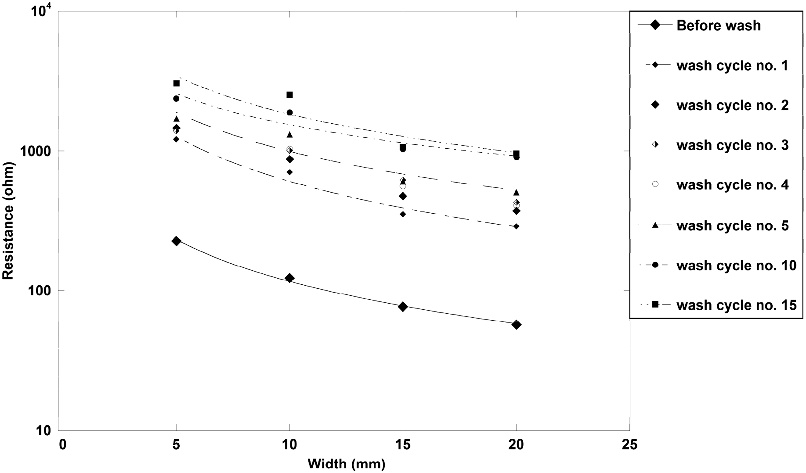
The results of the washability tests on the electrical resistance of the samples with different widths are presented in Figures 9 and 10. There was a clear increase in resistance for all samples already after the first wash cycle and all samples increased their resistance by at least one order of magnitude after 15 wash cycles. Within the first five wash cycles, the average surface resistivity remains at less than 500 Ω/square, which should be an acceptable level for the application.
26
Influence of washing on the resistance of printed samples of different widths; 5, 10, 15, and 20 mm. Resistance of samples before and after washing organized after their widths, displaying power-law curve fits.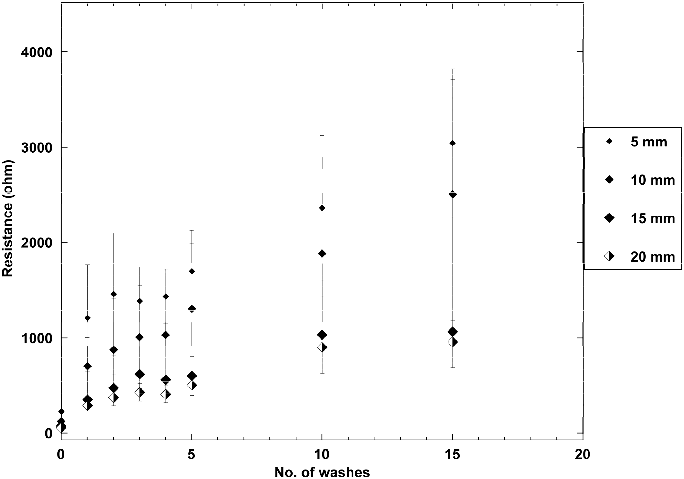
The standard deviations displayed in Figure 9 increased greatly with the narrower samples compared to the wider, for which the measured values appeared rather stable. The narrower prints are perhaps more susceptible to penetration of water, but this should rather have resulted in an increase in resistance than an increased standard deviation. Plausible explanations could be that narrower prints were more sensitive to irregularities and to variations in the contact area to the measurement probe.
Considering the structure of PEDOT:PSS, where the conductive PEDOT-oligomers are in a complex with, and surrounded by, water soluble PSS, the washability results were surprisingly good. This indicates that the crosslinking binder manages to entangle the conductive network and functions as an adhesive between the PEDOT:PSS and the knitted substrate. Although the preferred scenario would be that no increase in resistance occurred after washing, it is highly plausible that the interconnections would still remain functional after 15 wash cycles. In real applications, such as that of the motion sensing glove suggested here, the interconnections require a protective coating to avoid short-circuits to occur if they come into contact; this coating would also further increase their durability to washing.
Conclusions
This paper has presented a study of a motion sensing, entirely polymer-based glove with possible applications in physical rehabilitation. Important aspects of the glove were the textile production methods utilizing all-polymeric, safe and readily available functional materials as well as the possibility of the glove remaining comfortable and durable throughout use. For the first time, a piezoelectric yarn was integrated in a smart textile by machine embroidery, and proved to work well in spite of twisting and several subsequent heat treatments.
The screen-printing of conductive PEDOT:PSS interconnections was shown to be a reliable method for reproducible material deposition. A repeated strain of 10% only influenced the resistance of the interconnections initially, which implies that they would remain functional even during long-term use. A limiting factor for their longevity could be excessive washing, although the resistance after was is expected to be sufficient for the suggested glove application even after 15 washing cycles, depending on the system used to record the piezoelectric signal. In practical use, the interconnections would require a protective coating to prevent short-circuits and this would also further protect them from the detrimental effects of washing.
Footnotes
Funding
This work was partially funded by Sparbanksstiftelsen Sjuhärad (grant number 20111118), Västra Götalandsregionen (VGR) (grant number RUN 612-0197-13) through the Smart Textiles initiative, VINNOVA (grant number 2011-02377).