Abstract
A new textile fabric prototype providing more heat insulation composed of shape-memory elements was investigated. The shape-memory elements in the form of spirals characterized by two-way action were made of nitinol (NiTi) one-way wires with the inner state transition temperature of 35℃. The fabric prototype developed was made of three layers of nonwovens manufactured from the blends of flax and steel fibers and the two interlayers included spirals, made from NiTi or a reference copper (Cu) wire. The inner layer (heater) was heated by electrical current. The external prototype layers imitated the fabric. Mirrors and an infrared camera were used to measure the thermal properties. The temperature of the external surfaces was analyzed as a function of heating time. At approximately 35℃, a change in the curve of the dependence of temperature on the heating time of the prototype with NiTi elements could be observed; the rate of the temperature increase began to decrease. The width of the interlayer with air and NiTi elements increases by approximately 2.5 mm during heating. The observed phenomenon is caused by the expansion of the NiTi spirals and did not occur with the prototype composed of non-active reference Cu elements. In the final second of heating, the temperature on the external surface of the prototype with NiTi elements was lower by 2–3℃ than that on the prototype with Cu elements. A theoretical model of the system was developed and a satisfactory agreement between the experimental and theoretical results was obtained.
Owing to the advances in research and technology in the textile industry, smart materials characterized by variable, temperature-dependent parameters have been developed in recent decades.
Smart materials are most frequently defined as materials capable of significantly changing their properties in response to external stimuli, such as pressure, temperature, and humidity changes in the environment. In other words, a smart fabric is a material that, having reached a threshold value as a result of external conditions, converts the quantitative change of energy of this interaction into a qualitative change of its own properties, thereby performing a useful function once or repeatedly. Shape memory is one of the best known and the most common phenomena characterizing smart materials.
Materials with shape memory have two stable phases – a high-temperature and a low-temperature phase. These phases are referred to as martensite (low temperatures) and austenite (high temperatures). The latter phase is called the parent phase. Some of the properties of austenite and martensite differ significantly.1–3
Heating a material with shape memory in the martensitic state leads to a transition into the austenite state (Figure 1). The temperature at which the transition starts is referred to as the austenite transition temperature As. The temperature at which this process ends is designated as Af. As a result of cooling, the material in an austenitic state begins to change into martensite. The temperature at which this phenomenon occurs is designated as Ms, whereas the temperature at which the process is completed is designated as Mf.
Martensite-to-austenite transformation and hysteresis in dependence of temperature. ξ: percentage of martensite; As: starting temperature of the martensite-to-austenite transition; Af: ending temperature of the martensite-to-austenite transition; Ms: starting temperature of the austenite-to-martensite transition; Mf: ending temperature of the austenite-to-martensite transition.
4

The transition temperatures are affected to a great extent by the conditions of the metallurgic processing and the alloy composition. For practical applications, three different forms are important: martensite, martensite exposed to mechanical stress (superelastic), and austenite. In the martensitic state, the material is characterized by high plasticity and is easily deformed.
If a shape-memory material is subjected to deformation in the low-temperature phase, the deformation will be reversed, that is, it will return to its original shape after the transition to austenite. This is an example of the one-way shape-memory phenomenon.
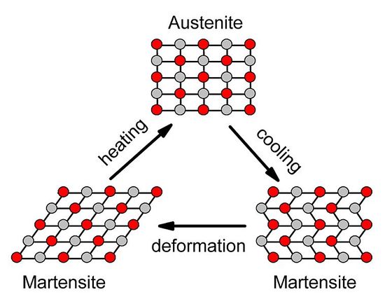
Figure 2 illustrates austenite-to-martensite transformations and the shape-memory phenomenon. This phenomenon is due to the crystalline structure of the material. In the martensitic phase, the crystalline lattice is in the “twinning” state, in which sufficient temperature increases or acting stresses cause a transition to the regular structure. This is accompanied on the macroscopic scale by the aforementioned shape-memory phenomenon.
Illustration of phase transitions in the shape-memory phenomenon.
5

The mechanical properties of shape-memory alloys (SMAs) are strongly related to the structural changes and the course of phase changes of the alloys. The chemical composition of SMAs and their production process considerably affect their phase constitution at a given temperature. The advantages of SMAs include corrosion resistance, a non-magnetic nature, low density, and high resistance to fatigue. They also possess a high resistance against impacts and thermal stress. The above properties contribute to the versatility of SMAs.
The first reports on shape memory date back to the 1930s. In 1959, the alloy named Nitinol (Nickel Titanium Naval Ordnance Laboratory) was elaborated upon. 2 Since this time, nickel-titanium (NiTi) alloys have been widely applied in medicine, including orthopedics, cardiology, and dentistry.3,5
Shape-memory polymers (SMPs) were discovered later than the shape-memory NiTi alloys. They were developed in Japan in 1984. 6 The change in shape of SMPs can be caused by various stimuli, such as light, electric, or magnetic fields, or by soaking the material in water. In addition to shape memory, these polymers are thermoplastic, which facilitates their production process, for example making a monofilament shape.7,8
Since 1998, many researchers have worked on the application of SMPs in smart textiles and clothing. There is a great potential in applying SMPs in the fields of textile and clothing, such as knitted fibers and woven fabrics/garments. 9
Elaborated shape-memory polyurethanes exhibit shape effects at temperatures of clothing manufacturers’ interest. Using a composite film of SMPs as an inter-liner in multilayer garments, outdoor clothing with adaptable thermal insulation or protective clothing can be made. 10 Despite the promising properties of SMPs, alloy elements with shape memory are still of interest in textile research centers. NiTi in the form of fine wires is suitable for being processed on textile machines. However, due to their stiffness and difficult handling in some textile processes, such as twisting and knitting, the application of thin SMA wires in textiles is still in the investigation phase, and only to a limited extent. Vasile et al. 11 investigated the possibility of compensating for the creasing of textile material by using SMA wires with a diameter of 300 µm. The thickness, wrinkle recovery, dimensional stability, and cohesion of the SMA wires in the woven fabric were tested. All the tests were performed before and after a washing cycle for both the hybrid and reference fabric. Vasile et al. 12 presented the analysis of hybrid yarns containing a superelastic SMA wire as the core, covered by textile yarns or fibers. Ahmad et al. 13 described their studies on the development of SMA core-sheath conductive yarns using a DREF 3000 friction-spinning machine. Vasile et al. 14 studied the possibility of using superelastic SMA wires to improve the wrinkle recovery of flax fabrics. The wrinkle-recovery angles of the hybrid fabrics were assessed under both dry and wet conditions and the results were compared with the results of reference linen fabrics. In Russel et al., 15 sprigs formed from one-way NiTi wire were stitched into a double layer of aramid fabric that was irradiated with a heat flux of high intensity (flame). The fabric after the experiment became charred and embrittled. The proposed product was non-recurrent.
In the present study, NiTi wire was used for making active elements and modeling thermal properties of textiles designed for dresses to be worn under mild temperature conditions. The two-way, spiral-shaped wire elements were formed from one-way wire, and placed into a specially developed nonwoven structure. The structure of the textile prototype was heated with the use of electrical power and can be used repeatedly. Thermal insulating properties were investigated by means of a thermographic camera. A theoretical model was developed and comparisons between experimental and theoretical results were made.
Aim of the study
The aim of this study was to develop a textile fabric with controllable heat insulation using smart materials. The smart material used consisted of elements with two-way action made of one-way NiTi. The NiTi elements were incorporated into nonwoven structures specially developed for measurement. With the application of heat, the volume of the structure increases, resulting in increased heat insulation. The heat application process is realized by changing electric energy into heat energy. This study was focused not only on the experimental examinations of the product prototype characterized by programmed thermo-insulating properties, but also on the development of a theoretical model of the processes occurring within such structures.
Materials
Nonwoven layers
All of the structural layers of the prototype were prepared from nonwovens made of flax and steel fibers. Steel fibers increase the electrical conduction of the nonwoven, and thereby make it possible to heat the system with electricity. Moreover, steel fibers are characterized by great stiffness and increase the nonwoven stiffness; the latter is an important parameter that will determine the deformation behavior of the structure in response to heating.
Flax fibers with an initial length of 207 mm and a linear density of 47 dtex were cut to obtain staple fibers with lengths of 70 mm. Steel fibers Bekaert Bekinox® W12/18 were characterized by length of 90 mm, nominal linear density of 9 dtex, and electrical resistivity 0.6 Ω·m. 16
Flax and steel fibers were blended twice on a laboratory roller card at a ratio of 60:40, respectively. The blend was then fed into an Asseline line consisting of a 3 K roller card, a horizontal stacker, and a needle-punching machine. Needling was conducted using a constant punching depth of 12 mm, and a needling density of 40 punches/cm2. The nonwoven obtained was then subjected to cold calendering under a pressure of 7 atm. To increase the fabric density, the nonwoven was wet-pressed (wetting up to 50% of the sample weight) using a laboratory garment press at a temperature of 150℃ for 15 min. The surface weight of the nonwoven was 450 g/m2.
The electrical resistivity (ρ s ) of the nonwovens prepared was determined according to European Standard EN 1149-1:200617 and was 85.14 Ω.
The thermal conductivity λ measured by an Alambeta 18 apparatus from Sensora (Czech Republic) was determined to be 0.041 W/m·K.
The specific heat of the nonwoven was experimentally determined using differential scanning calorimetry (DSC) 19 and was found to be 1150 J/kg·K. The apparent density of the sample placed in the representative cell of the DSC apparatus is higher than that of the nonwoven in a loose state; therefore, in calculations we took into account the presence of air in the nonwoven.
Active elements
A NiTi alloy wire with a one-way action and a transition temperature (As) of approximately 35℃ was used in the experiment. Its behavior during the temperature changes is illustrated in Figure 3. In the initial state, that is, in the martensite phase (cooling phase), the wire is subjected to deformation, and then, with the temperature increase in the martensite-to-austenite transition (heating phase), the wire assumes its initial shape.
Illustration of the one-way shape-memory phenomenon.
20

The wire exhibits one-way action; therefore, it does not automatically return to its initial state after cooling. Elements characterized by two-way action were prepared for experimental evaluation. Thus, spiral elements with the desired geometry were formed from the tested alloy wire with the shape memory at a temperature higher than the temperature at which the wire is in the austenitic state (Af). After cooling to a temperature below the austenite-to-martensite transition point (Mf), the spiral was compressed. Then the spiral was suspended in a vertical position and loaded with weight. The length of the spiral became elongated and the spiral was heated. Next, the load was removed; the spiral was placed under compressive stress and cooled. The length of the spiral was reduced to its initial length. To initiate the length decrease, the spiral must undergo an initial compression. After multiple repetitions of the heating under loading and cooling under compression cycles, the spiral memorized the set-up action, that is, without any load, it increases its length when heated to a temperature above the phase transition point Af and decreases its length when cooled to a temperature below the transition point Mf. The process of making the mentioned spirals and material with the two-way action for heat distribution has been patented. 21
Figure 4 schematically illustrates one active element of NiTi at the initial room temperature T0 ≤ Mf, in a heated state, that is, at T ≥ Af, and after returning to the initial state at temperature T0.
Schematic representation of the element at the initial and final temperature T0 and in the heated state at T > T0.
In addition to the NiTi active elements, there were also elements made of the same dimensions but from a conventional metal, such as copper (Cu). The Cu spiral elements were used for comparative tests. The geometry of both types of the metallic elements was the same. The diameter of the wires was 0.2 mm and the diameter of the spirals was 9 mm. Each spiral had five coils.
Structure of the textile fabric prototype
A prototype of a special nonwoven structure was developed. The structure contained three nonwoven layers and two interlayers.
Each layer fulfilled a particular function. The internal nonwoven layer was used to heat the structure and simulated a heat source. The two external layers imitated the textile fabric. The interlayers contained either the active NiTi spirals or reference, non-active Cu spirals. The NiTi elements were used to increase the thermo-insulating properties of the textiles. The Cu spiral elements were used for comparative testing.
The structures with NiTi and those with Cu elements were characterized by the same geometrical features.
All the nonwoven layers were rectangular with a thickness of 1.4 mm.
The length of the internal layer was 150 mm and the width was 50 mm. The internal layer was heated by electrical current and the electrical contacts were made from steel yarn. 16 The contacts were stitched by a simple seam with a distance of 100 mm between the contacts.
The dimensions of the external nonwoven layers were 50 mm × 50 mm.
The spirals were placed between the external and internal layers. The distance between elements in plane was 12.5 mm × 12.5 mm. The spirals were fixed to each layer with the aid of thin flax thread. The interlayer thickness in the initial compressed state was 1.0 mm. The layers were connected to a loose seam to enable the expansion of the active elements if necessary.
The structure was characterized by a geometric symmetry in relation to the plane running through the middle of the internal layer.
Figure 5 displays a schematic of the textile fabric prototype.
Textile fabric prototype with NiTi elements. 1: electrical contacts; 2: external nonwoven layers; 3: NiTi active elements.
Two external layers were placed symmetrically along the plane of the inner layer to enable the use of the mirrors required for the selected test method. The heat flowed from the heating layer through interlayers with spirals, beyond the external layer, and finally to the surroundings. In the real prototype, only one-half of the structure with the inner layer simulating a heat source, interlayer and external layer imitating, for example the cloth, should be used. This means that the inner layer of the developed structure simulates the surrounding environment and the outer layer of clothing simulates the layer close to the skin surface.
Three types of textile fabric prototypes were prepared. The first consisted of structures that incorporated active elements in the form of NiTi spirals (NiTi-NiTi) situated between the heating and external layers on two sides of the structure (Figure 5). The second type had incorporated reference elements in the form of a Cu wire spiral (Cu-Cu) situated between the heating and external layers on two sides of the structure (Figure 6(a)). The third structure, (Cu-NiTi), had NiTi spiral elements incorporated between the heating and external layers on one side and Cu spiral elements placed between the heating and external layers on the other (Figure 6(b)).
Textile fabric prototype with active and non-active elements. (a) Cu elements on both sides. (b) Cu elements on one (left-hand) side and NiTi elements on the other (right-hand) side.
Methods
Test method
The mirror test method developed by one of the authors of this paper 22 was used. The measuring set-up consisted of an infrared (IR) camera and mirrors reflecting IR radiation (IR mirrors).
The structure was placed on the measuring stand consisting of a thermographic camera linked to a computer, two IR mirrors vertically positioned at angles of 90°, and a supply system to the heating layers. The textile fabric prototype was placed symmetrically between the mirrors in a vertical position. The heating layer was connected to an electric current source, whose power was registered. A direct current (DC) Power supply AX-3003 D was used to provide power. The internal layer of the structure was heated directly by the current flow while the active elements and external layers were heated indirectly by the outward flow of heat from the internal layer.
Figure 8 displays a photographic view of the measuring stand.
Schematic of the configuration of the measuring stand used during experimental testing. IR: infrared. Photographic view of the configuration of the measuring stand used during experimental testing.

The temperature distribution on the surfaces of both of the external layers were reflected in the mirrors, which are the part of the measuring stand, and recorded by a FLIR SC5000 thermographic camera. Figure 9 depicts the reflected images of the external surfaces of the textile prototype with examples of measurement points.
View of the textile prototype on the stand with reflected external surfaces in which 1 and 2 are examples of the points analyzed.
Figure 10 depicts an example of a recorded thermogram displaying the temperature distribution on the external surfaces of the structure.
An example of a real thermogram with marked areas and points for analysis.
The temperature dependency on time on opposite points of the external prototype surfaces during prototype heating was analyzed. The points positioned in the middle areas of the external layers were selected for the analysis (points 1 and 2 in Figure 10). The results obtained were processed using the ALTAIR application.
Mathematical model
The mathematical model based on Michalak 22 in order to determine the thermal conductivity of such materials has been established. To aid theoretical development, a representative structure was proposed, as shown in Figure 3.
The structure proposed is characterized by identical conditions of heat exchange on the external surfaces of the representative structure. It is assumed in the mathematical model that the distribution of temperature is symmetric in relation to the YZ plane (Figure 11(a)). Therefore, the representative structure was divided into two equal parts, leading the parting face through the heating layer middle and leaving just one part for analysis (Figure 11(b)).
The scheme of the structure analyzed in the mathematical model: (a) representative structure; (b) part of the representative structure analyzed in the mathematical model.
External layer dimensions are denoted as bx, by, bz respectively to coordinate axes.
The mathematical model describing the temperature field in the external layers tested was formulated on the basis of Equation (1), the general Kirchhof–Fourier equation for a three-dimensional system.23–25
In the general case, the specific thermal conductivity is a function of both coordinates and temperature wherein
During development of the boundary conditions for analysis of the external layers, it was assumed as follows. (1) The heat supplied to the layer heated by a direct flow of electric current heats the external layers and drifts into the surroundings. (2) The heater loses heat to both external layers as these are prepared in the same way. Each of the external layers then receives an identical portion of thermal energy. (3) Under the assumptions made, a power equal to 50% of the heater power flows into each of the external layers. It was also assumed that the heating layer is uniform and the surface heated is situated at a zero distance from the origin of coordinates. Moreover, it was assumed in the model that the heat capacity of the heater is low enough that the entire amount of electric energy was converted into thermal energy and is supplied to the external layers.
Heat from the external layers is lost to the surroundings by natural convection and IR radiation. The heat lost by convection is denoted as Qk, and the heat emitted is denoted as QIR.
The heat transmitted to surroundings by convection may be expressed
23
by means of Equation (2):
The coefficient of natural convection can be calculated using Nusselt’s criterional number
23
in the form of
The emitted IR heat can be calculated from Equation (4):
Denoting the heat lost from the heating layer with symbol Qe, boundary conditions can be formulated as follows:
Although the XY surfaces are situated near the area adherent to the textile electric contacts and are subjected to the action of heat emitted in the heating layer that heats the external layers, it was assumed that there is no heat exchange with surroundings.
The initial condition is the initial external layer temperature. It is assumed that it is equalized on both sides and is the same as the ambient temperature, T0.
To solve Equation (1), it should be taken into account that the part of the energy, which was supplied to the inner layer with spirals, is absorbed by the NiTi elements during the martensite–austenite transition. Another part of the energy is used for mechanical work that was performed during the expansion of the spirals. All of these phenomena cause changes in thermal conductivity, specific heat and apparent density of the space between the inner and outer layers (i.e. air layer with spirals). The mentioned phenomena are taken into account by the introduction of a substitute, variable during heat supply, specific heat, and the apparent density of the layer with spirals.
To solve Equation (1), it was assumed that the model structure (Figures 5 and 6) consists of three layers: layer 1 – the heating layer, layer 2 – the interlayer containing the spirals, and layer 3 – the external nonwoven layer.
For the structure with NiTi elements, the following assumptions were made:
layer 1 of the structure is characterized by a low thickness that was omitted in the model; the specific heat and apparent density of layer 2 decrease during the application of heat; the thermal conductivity of layer 2 decreases during the application of heat; the parameters of layer 3 remain unchanged during testing.
The structure with Cu spirals was considered as a homogeneous solid with equivalent invariable parameters, that is, it was assumed that the specific heat conductivity, specific heat, and apparent density remain constant during testing and the same for the whole structure.
The heating power supplied was recalculated per unit of the surface heated.
To solve Equation (1), which describes the thermal field in the structure with the boundary conditions outlined in Equation (5), the commercial program FlexPDE 6 was used. The calculations were performed only for the heating process.
The research was performed according to a scheme:
performing the thermographic measurements and obtaining the course of temperature in the function of time; computer iterative calculations at the assumed initial values of specific thermal conductivity λ; comparison of the calculation results with the measured results; performing of the calculations for changed values of λ until obtaining conformity of the calculation results with the measured results; acceptance of the determined specific heat conductivity.
Results and discussion
Experimental results
Figures 12–16 illustrate the temperature dependencies on heating time for all the prototypes discussed previously. In the experiment, the applied voltage and the current were chosen to produce electric power that was 1.71, 1.91, and 2.25 W. The heating power was chosen to enable the temperature of the prototype to be maintained within the range of temperatures in which the clothing would be worn. The heating process lasted 240 s and data were recorded for 600 s (10 min). Then, after disconnecting the power source, the cooling process followed. Thermograms were recorded at a frequency of 1 frame/s.
Experimental temperature dependence on the time of the NiTi-Cu prototype. Power = 1.91 W; NiTi: the side with NiTi elements; Cu: the side with Cu elements. Experimental temperature dependence on the time for the Cu-Cu prototypes. Power = 1.91 W. Experimental temperature dependence on the time of the NiTi prototypes. Power = 1.91 W. Experimental temperature dependence on the time of the Cu-Cu prototype for several power values. Experimental temperature dependence on the heating time of the NiTi-NiTi prototype for several power values


The results provided in Figure 12 present the temperature profiles obtained for the symmetrical points on the external surface of the NiTi-Cu textile prototype when 1.91 W of power was applied. The patterns of the temperature profiles obtained at the other power values, 1.71 and 2.25 W, are similar, and are not presented in order to simplify the readability of the figures.
It can be observed from the graphs presented in Figure 12 that the temperature of the external surfaces of the textile prototype increases as the amount of heat supplied increases. The comparison of the temperature dependencies on heating time, that is, on the amount of the heat supplied, indicates that the external layer on the side with the NiTi elements is characterized by a more gradual change with time than that of the external layers with Cu elements. In the 240th second of heating, the layer with Cu elements is characterized by a higher temperature (41.5℃) than that of the layer with NiTi elements (40℃). When measuring we could observe that the space between the inner layer and external layer placed on NiTi elements increased by approximately 2 mm during heating, and the analogical space with Cu elements remained without changes. An increase in the space between the layers was observed in all prototypes with NiTi elements.
Each of the following figures reveals temperature dependencies on heating time at the central point for both external surfaces of the prototypes with the same elements on two sides of heating layer.
Figure 13 illustrates the temperature dependence on heating time of the prototypes with Cu elements in both sides.
The analysis of the temperature dependence on the heating time of the prototype with symmetrically incorporated copper elements indicates that the temperature of the prototype’s external surface increases within the entire time range, except that at the 130th second of heating when a small disturbance is observed. The maximum temperature achieved is 40.5℃.
Figure 14 presents the temperature dependence on heating time for the structure with NiTi active elements incorporated into both sides.
In the first 50 seconds of heating, the temperature of the external surface of the prototype linearly increases up to 36℃ (the temperature of austenite to martensite phase change is 35℃). Then, from the 50th second, the rate of temperature increase drastically decreases; at the 200th s, the temperature increases up to 38℃ and is constant up to end of heating at the 240th second.
A comparison of the graphs in Figures 13 and 14 exposes considerably different time traces. For NiTi structures, the temperature increases in the first short period of heating and then increases very slowly in the second, while in the case of Cu structures, the rate of increase during the second period is notably faster. The maximum temperature in the central point of the external layer of the textile prototype with NiTi elements implemented in both sides of the prototype is two degrees lower than that in the central point of the external layer of the textile prototype with copper elements. This difference is because of the appearance of air space between the heating and external layers and greater heat absorption of the NiTi elements during the martensite–austenite transition.
Figures 15 and 16 present the results of measuring temperature dependencies on the heating time for the symmetrical textile prototypes (see Figure 6(a) and 6(b)) containing Cu-Cu and NiTi-NiTi elements on both sides of the heating layer. The results are given for various electrical power values. In the graphs below, when the structures are characterized by symmetry, the temperature traces are for the averaged values from two opposing points.
The results obtained indicate that in the structures with NiTi elements, the temperatures for all the electric power values are lower than those in the structures with Cu elements. In the first 35 seconds of heating at 1.71 W, 50 seconds of heating at 1.91 W, and 60 seconds of heating at 2.25 W, the temperature of the external surface of the NiTi-NiTi prototype linearly increases, and then the rate of temperature increase drastically decreases. A “saturation area” can be observed; particularly in Figure 16 at a heating power of 2.25 W. The structure with Cu elements does not exhibit saturation at any heating power.
The cooling process of prototypes with NiTi elements proceeds differently than that in prototypes with Cu elements. In the case of prototypes with Cu, from the 350th second to the end of recording, the temperature curves obtained at various values of heating power practically overlap, while the temperature profile of cooling for the prototype with NiTi elements proceed differently for each power of heating. This observation is the result of a differential in air space between the heating and external layers of the NiTi prototype.
Characteristic temperatures on the outside surface of the NiTi-NiTi and Cu-Cu prototypes

P: power of heating; t0: time when the course of temperature dependence on heating time of NiTi-NiTi prototype changes its character; T0: temperature at t0; Te: temperature at the end of heating, that is, in the 240th second of heating; ΔT: temperature difference at the 240th second of heating between structures composed of NiTi elements and the structure with reference Cu elements.
From Figures 15 and 16 and Table 1 it is observed that the rate at which changes in temperature versus the heating time of NiTi-NiTi structures and Cu-Cu structures differs. For Cu-Cu structures, the rate is steeper than that in the case of Ni-Ni structures, as is seen from the comparison of the Te – T0 difference values listed in Table 1. The temperature on the external part of the representative structure containing NiTi elements is lower by 2–3℃ than that of the reference structure with Cu elements. This would be a significant difference in the case of using the prototype in clothing.
Elastic material, which may have to initiate self-compression, 26 was not incorporated into the prototype and therefore it is unable to initiate the self-compression necessary to control the cooling process. Accordingly, controlled cooling was not discussed any further in the study presented.
In summary, the results presented in this study indicate the following.
The textile prototype with two-way NiTi elements is designed for clothing to be used under mild conditions. The results obtained for NiTi prototypes were compared with those obtained for the structure with non-active reference Cu elements. The rate of the temperature dependence on the heating time of the prototypes containing only reference Cu elements on two sides differs from the corresponding temperature profile of the prototypes containing NiTi elements. The curve of the dependence of temperature on time of the prototypes with NiTi elements on both sides is characterized by an area that can be called a “saturation area”, which begins (depending on the heating power value) approximately from the 35th to the 60th second of heating at a temperature from 33℃ to 39℃. This range includes the temperature value of 35℃ – the typical value of applied shape-memory material. The function of temperature versus time on external surfaces of Cu-Cu prototypes does not contain such a “saturation area”. The temperatures on external surfaces of the prototype containing active elements made of NiTi have lower values than the corresponding temperatures of prototypes containing Cu. The maximum difference between the temperature of the structure with NiTi elements and the temperature of the structure with non-active reference elements at the last second of heating was observed within the range of 2–3℃. The temperature increase results in the expansion of the NiTi spiral and an increase in the air space between the heating and external layers. The space between the layers after heating observed during the experiment was approximately 2–3 mm, depending on heating power.
The theoretical results
The calculations of the theoretical dependencies of temperature on heating time were performed using the assumptions outlined in the section describing the mathematical model. As mentioned previously, the theoretical structure consists of a heating layer, an interlayer with spirals, and an external nonwoven layer.
NiTi elements
Appropriate values of the specific heat and apparent density of the layer with NiTi spirals

For the external layer of the structure with NiTi the following independent on temperature (time) parameters were assumed:
The values of the substitute specific thermal conductivity (

The theoretical dependencies of temperature on heating time with obtained substitute specific thermal conductivity for the NiTi-NiTi prototype are shown in Figure 17.
Theoretical temperature dependence on the heating time of the NiTi-NiTi prototype for several power values.
At the 300th (as well as 240th) second of heating the temperature of the external surface of the NiTi-NiTi structure reaches 40℃, 38℃, and 36℃, using power values of 2.25, 1.91, and 1.71 W, respectively. The pattern of the dependence of temperature on the time shown in each curve is similar to the experimental dependencies. The fastest changes in temperature are observed in the initial heating phase. During a period of approximately 50 seconds the temperature increases rapidly and then becomes nearly constant.
Cu elements
As mentioned in the section on the theoretical model, the structure with Cu spirals was considered to be a homogeneous solid with parameters, including specific heat conductivity, specific heat, and apparent density, that remained invariable during heating.
Apparent density (ρ Cu ), specific heat, and specific thermal conductivity were calculated based on the data on copper in the literature, and the nonwoven parameters were determined experimentally. For the structure with Cu, the following parameters were assumed: ρ Cu = 300 kg/m3 and λ Cu = 0.1 W/m·K, CCu = 500 J/kg·K.
The theoretical dependencies of temperature on heating time for the Cu-Cu prototype are shown in Figure 18.
Theoretical temperature dependence on the heating time of the Cu-Cu prototype for several power values.
The temperature of the Cu-Cu structure increases during heating of the sample. At the 300th (as well as 240th) second, the temperature of the external surface of the Cu-Cu structure reaches 42℃, 40℃, and 38℃, using power values of 2.25, 1.91, and 1.71 W, respectively.
Comparison of theoretical and experimental results
The compatibility of the theoretical and experimental results are observed both for the structures with NiTi and for those with Cu elements.
For the respective structure, the rate of the theoretical temperature-time dependence is compatible with experimental dependence observed at the same heating power.
Maximal differences in the rates of the compared theoretical and experimental curves are detected during the initial time of heating from 0 to 50 s. The fact confirmed that this incompatibility is a natural phenomenon because the theoretical model was developed with simplified assumptions.
For all structures, that is, those with NiTi or Cu spirals, the determination coefficient (R2) was calculated.
The values of determination coefficient for NiTi-NiTi and Cu-Cu structures.

The lowest value of the determination coefficient, 0.79, is obtained for the Cu-Cu structure at 1.71 W, the lowest heating power. The highest value of the determination coefficient, 0.93, is obtained for the NiTi-NiTi structure at 2.25 W, the highest heating power.
In general, the conformity of the theoretical and experimental curves is better for NiTi-NiTi structures than for Cu-Cu structures.
The determination coefficient for a NiTi-NiTi structure at a heating power of 1.71 W is 0.92, and for a Cu-Cu structure, it is 0.79.
The determination coefficient for a NiTi-NiTi structure at the heating power of 1.91 W is 0.91, and for a Cu-Cu structure, it is 0.92.
The determination coefficient for a NiTi-NiTi structure at the heating power of 2.25 W is 0.93, and for a Cu-Cu structure, it is 0.92.
It is observed that satisfactory agreement of the experimental and theoretical results is obtained in the time temperature range interval from 50 to 260 s.
Conclusions
Several conclusions can be drawn as a result of this study.
A new multilayer textile fabric prototype providing more heat insulation was developed through the use of shape-memory elements. The incorporation of the shape-memory material into textile structure makes it possible to increase heat insulation because of the increase in the air layer thickness in the transverse direction of a flat textile fabric. At a temperature of approximately 35℃ (the temperature of austenite to martensite phase change) the observed space between the layers of the prototype with NiTi elements is increased to approximately 2–3 mm according to heating power. In the case of the prototype with NiTi elements, at the temperature of the austenite–martensite transformation (approximately 35℃), the temperature increase rate is decreased depending on the heating time. The prototypes with Cu elements are characterized by a stronger relationship between temperature and heating time. The theoretical results obtained based on the model exhibit remarkable similarity to the experimental results. The temperature range within which the activity of the elements occurs and the appearance of the temperature versus time profile can be regulated by selecting a proper material with shape memory. The heat-induced variation of the interlayer spirals can be electrically regulated, thereby providing a means to control changes in the overall insulation capability of the prototype material. The expanded spiral condition can be maintained for an unlimited period of time. If remote control of the heating process could be achieved, then it could be possible to use the product developed for special practical purposes, including use as military materials. Generally, thermal resistance of common clothing should increase when the outside temperature decreases, in order to protect the clothing wearer against high heat loses in winter. The presented solution is not suitable for use in standard clothing. The prototype of the presented model is designed to protect against the effects of hot entrusts, such as special clothing in countries with warm climates, as a protection from excessive overheating of the body. The inner layer of the developed structure simulates the surrounding environment and the outer layer of clothing simulates the layer close to the skin surface. The proposed fabric can be used only when special cooling means are simultaneously employed, due to metabolic heat generated in the human body.
Footnotes
Funding
The work was done as part of Research Project 3 T08E 050 28, financed by KBN - The State Committee for Scientific Research of Poland, entitled “3688/B/T02/2009/36 Elaboration of a method for the evaluation of the temperature dependent thermal parameters of smart textile materials”.