
Abstract
In industrial sewing, needle heating is a key problem that limits the further increase of sewing speed, and hence the productivity. Heat is generated during the sewing process because of friction between the needle and the sewing thread as well as between the needle and the fabric. The high temperature of the needle affects the quality and productivity of the sewing. The problem of needle temperature rise due to friction heat generation is considered in this paper and a simple analytical model is developed to predict needle temperature. The predicted needle temperature is compared with the experimental results by the inserted thermocouple method. Some of the process parameters, used as input variables, were also measured experimentally and experimentally observed values of needle temperature were compared with the theoretical prediction. It was observed that the temperature of the needle increases significantly with the presence of the sewing thread. Both the theory and the experimental results show that the needle temperature increases linearly with the machine speed within the ranges studied.
Keywords
Industrial sewing is one of the most common operations in the manufacturing of garments, shoes, upholstery and technical fabrics for automobiles. Every day, millions of products, ranging from shirts to automotive airbags, are sewn using industrial sewing machines. Heavy industrial sewing, such as that used in the manufacture of automobile seat cushions, backs and airbags, requires not only high production but also high sewing quality (i.e. better appearance and seam strength). Typically, the material being sewn includes single and multiple plies of fabric or leather, sometimes backed with plastics, and needle heat-up due to needle to fabric and needle-to-thread friction is a major problem on the sewing floor. In recent years, in order to increase production, high-speed sewing has been extensively used. Currently, sewing speeds range from 1000 to 6000 r/min. In heavy industrial sewing, typical sewing speeds range from 1000 to 3000 r/min.
Depending on the sewing conditions, maximum needle temperatures range from 100℃ to 300℃. 1 This high temperature weakens the thread, since thread tensile strength is also a function of temperature, 1 resulting in decreased production. 2 In addition, the final stitched thread has 30–40% less strength than the parent threads. 3 The very high temperature of the needle can also damage the materials, such as some synthetic fabrics or plastics that come in direct contact with the needle during the sewing process. Since generally an increase in the machine speed is accompanied by an increase in the needle temperature, an optimization is often required. Therefore, it is important to understand the causes of the heating of the needle in a sewing machine and to be able to predict the maximum needle temperature from the various parameters of the machine, process and material.
However, the measurement of the temperature of the needle of a sewing machine during its operation difficult, since the needle moves at a very high speed 4 and its diameter is generally around 0.6–1.5 mm. Nevertheless, various methods for measuring needle temperature, such as infrared pyrometer, thermocouple and temperature sensitive waxes, have been used. Sondhelm 5 used a lacquer painted in the needle groove to observe a change of color with temperature. Laughlin 6 tried to measure needle temperature through infrared measurement from the needle using a lead-sulfide photocell. Recently, Yukseloglu et al. 7 observed the needle temperature by thermal camera for polyester blend fabrics for a sewing speed of 3000 r/min using a chromium needle and the emissivity was considered as 0.07. For infrared temperature measurement, there is a problem in calibration because the amount of radiation emitted at a higher temperature depends on the surface characteristics. 8 The emissivity of each needle must be determined individually and, indeed, the emissivity might change during the high-speed sewing process. Another technique using thermocouples was later developed by Dorkin and Chamberlain. 9 As a result of such variety of measuring methods used by various researchers, it is sometimes difficult to compare the results reported in the literature. Nevertheless, as a result of improved understanding of the causes of sewing damage, many technical developments, such as improved needle design 10 fabric finishes, 11 thread lubrication and needle coolers,12–15 have taken place over the years.
There are few theoretical models available to predict sewing needle temperature.4,8,16,17 Trung and Kùs 16 used the finite element analysis (FEA) model, while Li and Liasi 4 and Howard and Parsons 17 have used analytical as well as FEA models and reported that the FEA approach gives much better accuracy compared to their analytical models, which had an average error of 25%, but these methods cannot be used easily on the sewing floor to predict the needle temperature.
In the present study, therefore, the objective is to analyze the heat generation and transfer mechanism during sewing in an industrial sewing machine and to develop a simpler model for prediction of maximum temperature of a needle within a 15% error.
Theoretical model
Analytical models offer simplicity and fewer computational demands. On the other hand, numerical simulation gives better accuracy but is complicated and time consuming. In this study, unlike the previous models, two sources of frictional heating have been considered as a general case. The two sources are one due to contact friction between the needle surface and the fabric and the other due to contact friction between the inner edge of the needle eye and the sewing thread.
In this model, the following assumptions are used.
Needle, sewing thread and fabric are all at room temperature Ti initially before the sewing starts. The needle has uniform material properties throughout its length and can be assumed as a cylinder. The thermal conductivity of needle material λN is much higher than the thermal conductivity of the sewing thread λS, as well as than the thermal conductivity of the fabric λF. Here it is implicitly assumed that both the yarn and fabric can be assumed to have lumped thermal properties, that is, each has uniform thermal conductivities, represented by single values. Since the total needle surface area is small, radiation heat loss is neglected. In this model, it is approximated that the friction heat is given as Q = F.v,
1
where F is friction force and v is the relative velocity of the rubbing surfaces. The needle gains heat energy due to frictional rubbing with the fabric, where the frictional force is denoted by FF. The needle also gains heat due to frictional rubbing between the sewing thread and the needle eye, where the frictional force is denoted by FS. In the case of the heat generated due to frictional rubbing between two materials, part of the generated heat will go to one and the rest will go to the other material. Here it is assumed that there is no other way of heat loss at the points of friction. A partition ratio, γ, is considered to calculate the heat distribution between the rubbing surfaces. In this study, the partition ratio is calculated using Charron’s relation
18
as
The heat partition ratio between the needle and fabric is

Heat is generated during the sewing process as a result of friction between the needle-fabric and needle-yarn. In this analysis, a steady-state condition is considered in which the amount of heat generated by friction exactly equals the amount of heat loss by the needle. The complex shape of the needle is neglected, and it is treated as a uniform cylinder.
The heat generated due to rubbing between the surface of the needle and the fabric can be expressed as

The heat generated due to rubbing between the sewing yarn and the needle can be expressed as


From the first law of thermodynamics in a closed system:

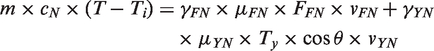
The above equation, for a more precise result, should be solved by evaluating it numerically over time, as many of the variables present in Equation (5) are complicated functions of time. However, in order to simplify the calculations, the maximum values of FFN and T will be considered here for the prediction of maximum temperature of the needle. Similarly, the maximum relative speed between the sewing thread and the needle will be used as

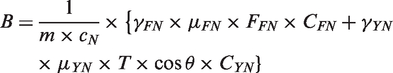
Thus, Equation (6) indicates that the maximum needle temperature is a linear function of machine speed. The prediction of maximum temperature of the needle from the machine speed is possible if the parameter B can be evaluated using Equation (7) for the sewing process with thread:
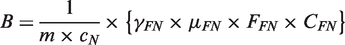
Equation (8) can be used for the calculation of parameter B for the sewing process without thread. This equation will be helpful to compare the results with the literature results, as most of the previous research of needle temperature prediction is done for dry sewing (without thread) due to complications in the measurement of needle temperature with thread.
Material and methods
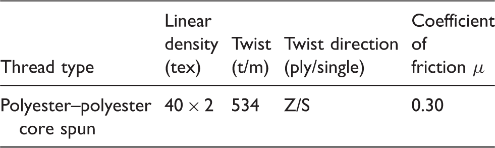
Sewing thread used for the experiments
Fabric used for the experiments

Needle temperature measurement
The experimental measurement of needle temperature with the inserted thermocouple method shows better repeatable and reproducible results. 19 In this technique of measurement a thermocouple is inserted into the groove of the sewing needle and soldered. The thermocouple is located near the eye of the needle to measure the exact needle temperature at different sewing speeds. This method proved to be very efficient, as it provides continuous changes in needle temperature with respect to sewing time and gives low standard deviation. The thermocouple remains inside the needle groove during the sewing process and measurements are recorded wirelessly on a computer through a wireless device.19,20
Sewing thread velocity measurement
During the stitch formation the bobbin assembly pulls the sewing thread, which makes the speed of the thread higher compared to the needle speed. The thread speed is measured experimentally by using a high-speed camera (OLYMPUS i-speed 3) during the sewing process. The white thread was marked with red ink at every 5 cm of its length to see the movement of thread and distance travelled by the thread during high-speed sewing (1000–4000 r/min). Thread velocity is not constant within a stitch and is maximum when the bobbin assembly pulls the thread downwards for the loop formation. Figure 1 shows one frame of the stitch formation motion captured by a high-speed camera. Colored marks (marked A in red color) on the sewing thread are made to follow the motion of thread and measure the thread velocity during stitch formation.
Analyzing the thread speed during sewing using the software i-speed 3. (Color online only.)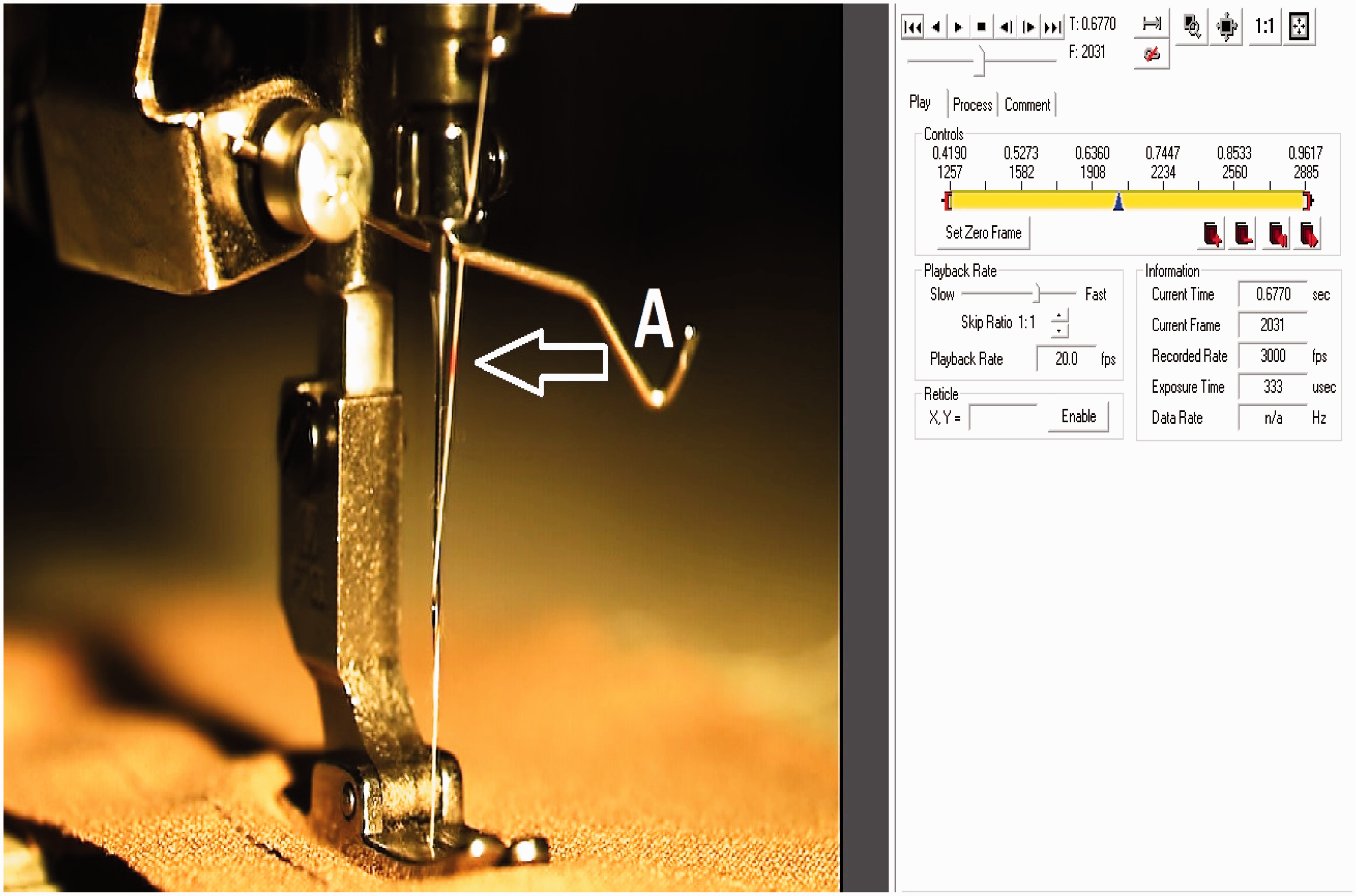
Needle penetration force
Fabric and needle interaction is the second major cause of needle heating. To measure the friction forces it is necessary to know the exact value of the normal force acting on the needle by the fabric. The needle penetration force depends on different fabric properties, such as fabric thickness, weave style and yarn count, and can be measured experimentally. Some researchers21,22 have used a tensile tester with special attachments to experimentally measure the needle penetration force. The same technique was used in this research work to measure the penetration force. Measurement of needle penetration force is performed on a tensile tester (Testometric Company). In order to hold the fabric samples on the machine, a custom-made metal frame with 3 mm of hole for the needle passage was used on the lower jaw of the machine. The cyclic needle penetration was performed 20 times for two layers of denim fabrics and the needle insertion speed was adjusted at 0.46 m/min. The machine setup for needle penetration force is schematically shown in Figure 2.
Schematic diagram of needle penetration force measurement, where A is the needle holder in the upper jaw, B is the needle holder, C is the needle, D is the fabric layers and E is the fabric holder with a hole at the lower jaw.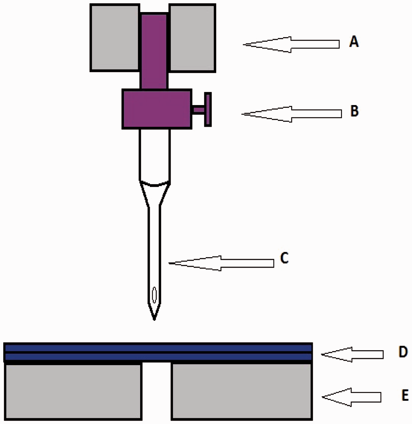
Friction measurement
To theoretically analyze the sewing needle temperature, it is necessary to know the coefficient of friction between the needle and thread for sewing. The thread-to-metal coefficient of friction is measured with instrument CTT-LH401 (Lawson-Hemphill) according to standard ASTM D-310.
Results and discussion
The maximum thread velocity with respect to the needle is measured using a high-speed camera and shows a linear relation between sewing speed and maximum thread velocity, as shown in Figure 3. It can be observed from the figure that maximum velocity of sewing yarn is a linear function of machine speed with multiplier constant CYN = 0.0244.
Variation of maximum thread speed with different machine speeds.
Similarly, the needle penetration velocity is measured as the needle moves 23 mm down and 23 mm back for one stitch formation and increase in needle speed is linearly related to the sewing machine speed. It can be observed from Figure 4 that the maximum velocity of the sewing needle is a linear function of machine speed with multiplier constant CFN = 0.0008.
Variation of maximum needle speed with different machine speeds.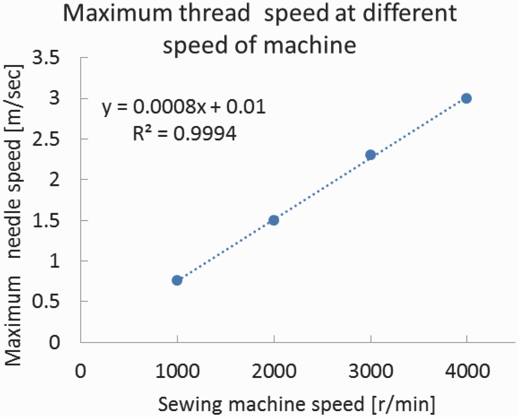
The needle penetration force is measured by using the special attachments to the tensile tester. The needle is inserted in to the fabric and the penetration force is experimentally calculated. Figure 5 shows the needle penetration force in the fabric; the experiment is repeated at five different places of the fabric. The peak in the graph is the needle penetration force and the height of the flat plateau between two peaks shows the force acting on the needle after the fabric is punctured and the needle moves across the fabric. This needle penetration force measurement technique is also used by some researchers21,22 and the same technique is followed here, as the penetration force may depend on needle dimensions and fabric weave structure, so it is necessary to know the exact penetration force with the sewing needle and fabric that was used in this study. The needle penetration force was measured at approximately the minimum level of the needle speed that has been considered in this study. Since no exact relationship between the needle penetration force and the machine speed was available from literature, and the same study was beyond the scope of this research work, the authors assumed that the variation of the needle penetration force within the range of machine speeds used in this study can be neglected. This means that it is assumed that the error involved by assuming a constant needle penetration force is within the overall error between the theory and the experimental results.
Variation of force on the needle during needle insertion.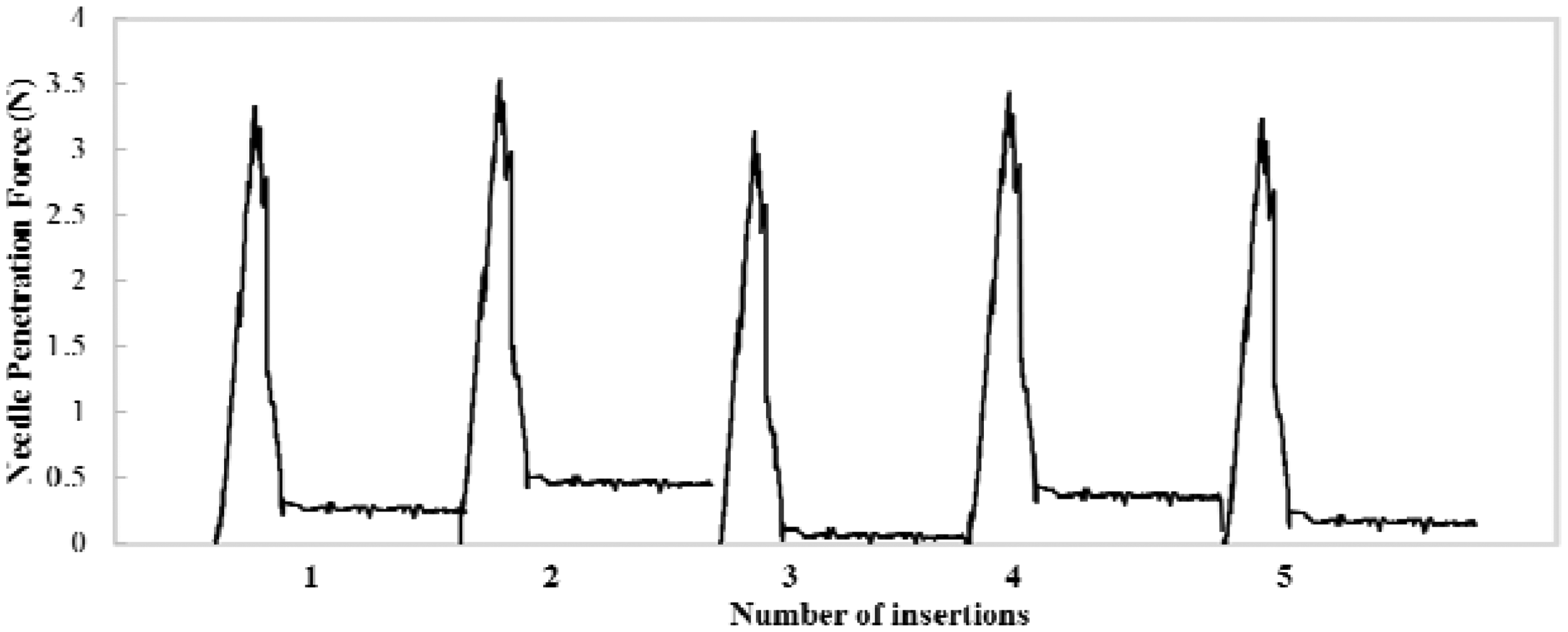
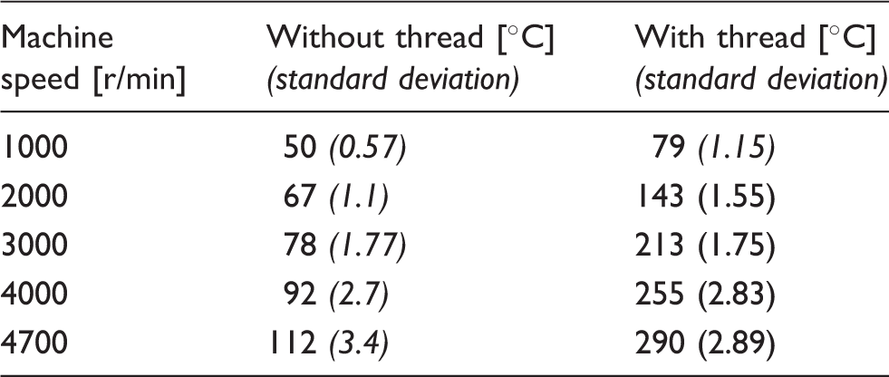
Experimental results of needle temperature measurement
Comparison of experimental results and theoretical model
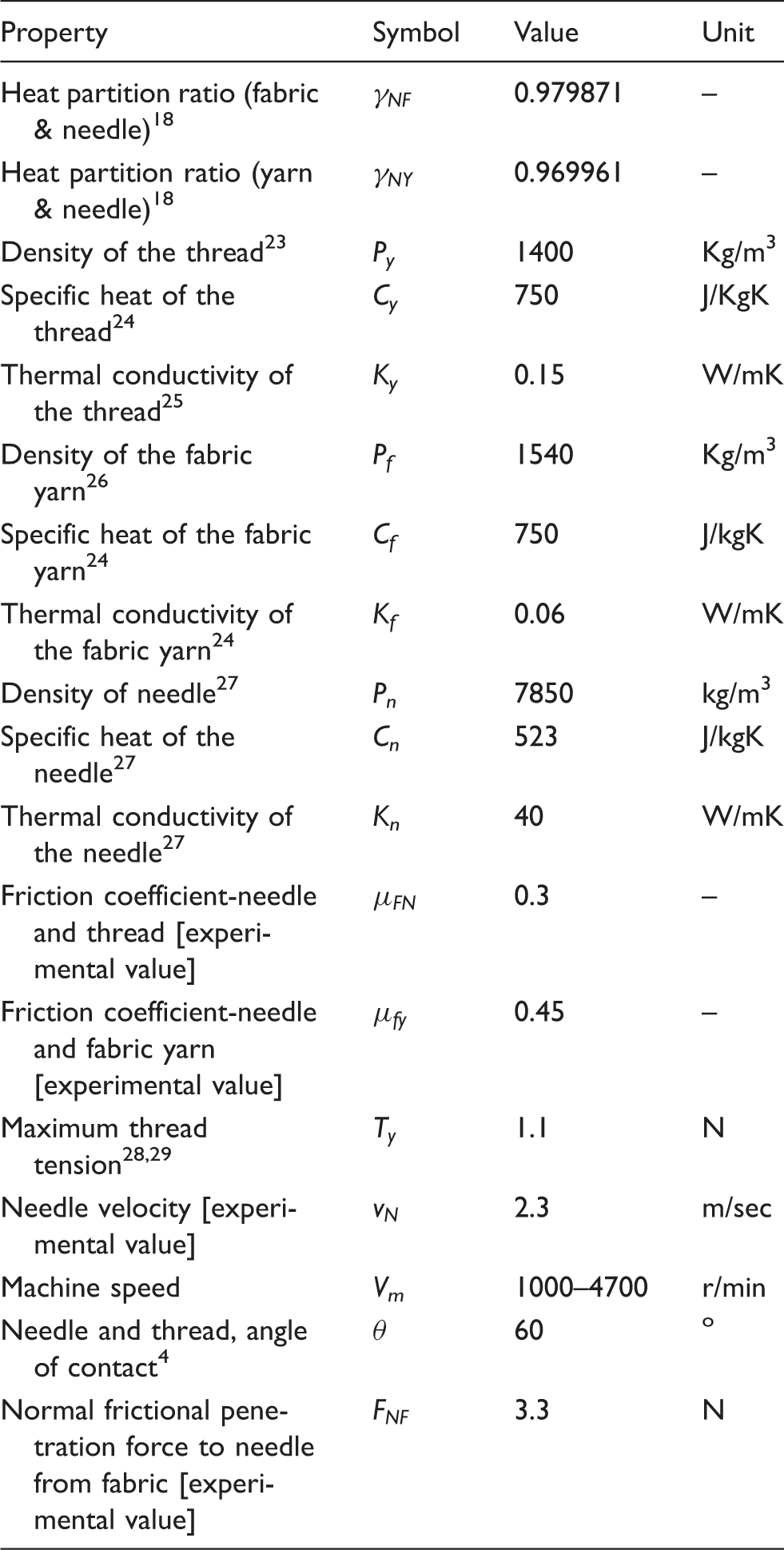
The needle temperature was calculated using Equations 6 and 7. Figure 6 shows the comparison of calculated values and the measured temperatures against machine speed. Table 4 summarizes the values used for the various parameters for this calculation. Values for material properties, such as specific heat, thermal conductivity and density of the needle material, have been taken from the literature as their exact measurement was clearly beyond the scope of this study.
Comparison between theoretical prediction and experimental observation for needle temperature against machine speed. Values of various parameters used for the theoretical prediction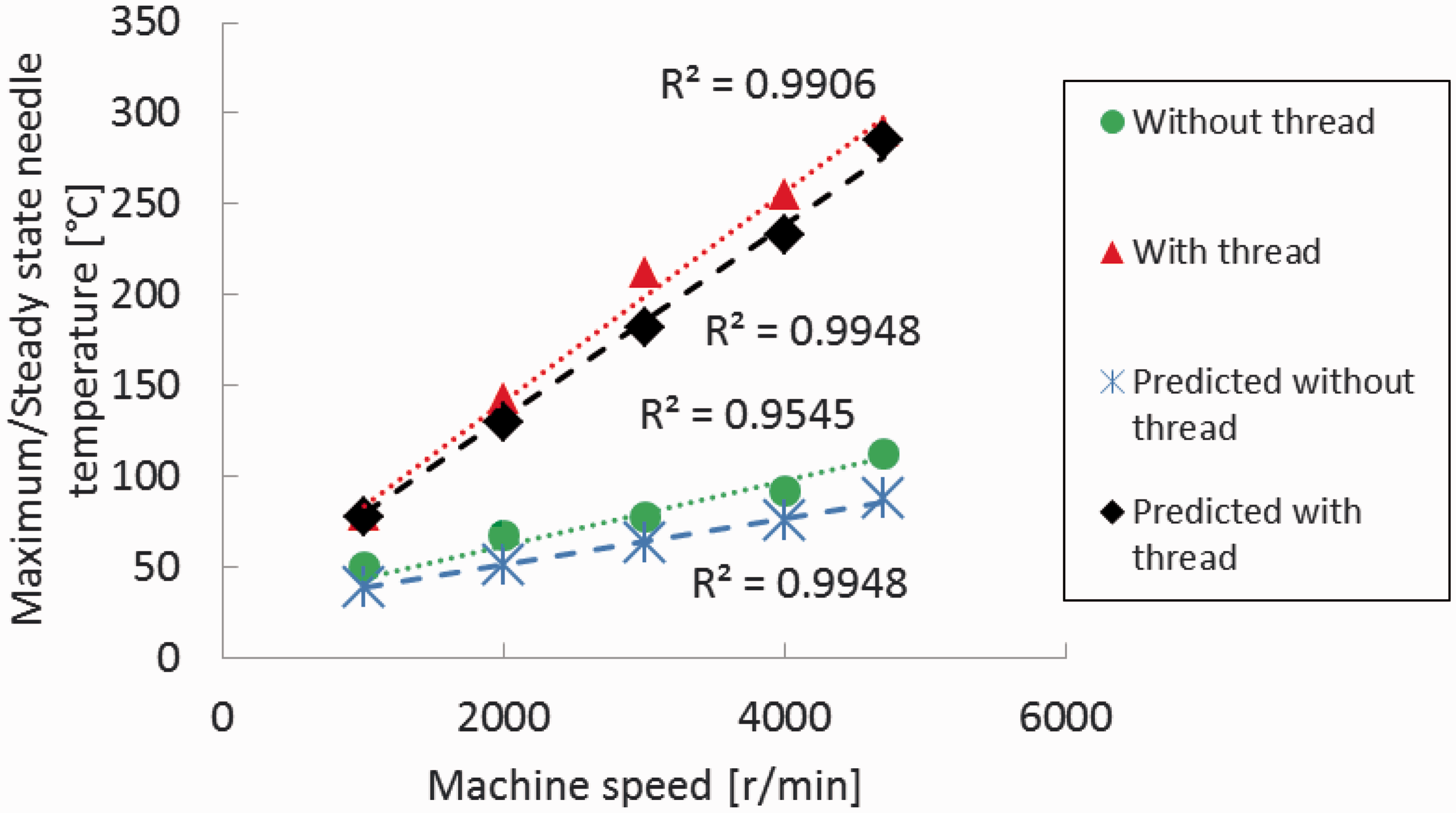
As can be seen from Figure 6, the calculated values seem slightly lower than the actual values and such error could be expected, since a number of approximations have been made to simplify the model and some of the values used for the calculation were not measured but obtained from the literature. Nevertheless, the simple theoretical model is able to indicate the fact that the presence of sewing thread contributes to the needle heating, which has been ignored by some previous literature and it also gives a linear relationship between the machine speed and needle temperature as observed by experiments. This simple approach may be more useful for the shop floor compared to the complicated numerical methods.
Needle temperature comparison with previous researcher’s results (without thread)

Conclusions
Friction between the needle and sewing thread is one of the major sources of needle heating. In general, the needle heating is a complicated heat transfer problem. In this work, a simple analytical model was developed to calculate the needle temperature at steady state from a set of parameters including friction coefficients, friction forces and thread tension, and a simple linear equation was obtained with machine speed as the independent variable. Suitable experiments were carried out to measure the needle temperature using thermocouples. Some of the other process parameters used in the model were also measured to finally calculate the predicted needle temperature at a given machine speed. The important role of the sewing thread in contributing towards the needle temperature was also established both theoretically and experimentally. The results indicate that the maximum needle temperature at steady state is a linear function of the machine speed within the range studied in this work, and this linearity is explained by the simple analytical model.
The study shows that the maximum needle temperature against the machine speed can be predicted by simply fitting a linear trend line both without the sewing thread and with the sewing thread. Moreover, the sewing thread causes a higher rate of increase of maximum needle temperature with respect to increasing machine speed. The simple analytical model can explain the heating behavior of the needle with respect to various machine and material parameters.
The presented analytical model does not require extensive computation. As a result, it can be used to estimate the needle temperature on the sewing floor, provided certain material and process parameters as shown in Table 4 are available, and provide valuable information for optimizing the industrial sewing operation.
Footnotes
Funding
This work was supported by Technical University of Liberec (TUL), Czech Republic (grant scheme SGS 21031). The second author would like to acknowledge the ESF project No. CZ.1.07/2.3.00/30.0065, for funding his stay and research in TUL.