






Abstract
This paper provides a critical overview about the state of the art in the area of three-dimensional modeling of braided structures. It gives a generalized geometrical approach for modeling braided structures with arbitrary floating length and filaments in the yarn. The approach is tested with large set of structures of different types. Subsequently, one of the simulated geometries is compared with the real geometry of braided tube.
Braided structures are widely used as ropes, tubes, composites, medical and other applications. The prediction of their properties is the subject of several investigations, which gives partial solution for some specific cases, based on some assumption about the geometry of the yarns in the braid. There are several works that try to model the yarn orientation in the braid in the general case in order to provide good initial data for more application-specific mechanical calculations. Unfortunately, these proceedings do not yet cover all possible braided structures. This paper gives a critical overview of the recent works and methods used for modeling of braided structures and adjacently presents a unified approach for geometric modeling of braided structures with arbitrary floating length and yarns in a group.
State of the art
In this research only the related to the macroscale three-dimensional (3D) geometry works will be discussed. Because of the limited space, models that solely deal with unit cells of braided (and woven) fabrics are not considered. Moreover, one of the problems of some models, which is addressed in the third section in this paper, appears at the macro level even if the unit cell is correctly modeled, but wrongly oriented in the macro space.
In one of the most cited papers about 3D modeling, Liao and Adanur
1
sweep a two-dimensional (2D) simple closed contour
Kyosev
4
and Kyosev et al.
5
used an extended version of these equations, considering the undulations of the radius r on the places of contact points:
The profile of the mandrel is defined as a function in a discretized form
In the case that the yarns are stable positioned and do not slip around the crossing points, the complete set of yarn paths is generated and connected using splines, in a similar way to that reported by Pastore et al.,
7
who used Bezier curves, or Bogdanovich,
8
Bogdanovich et al.
9
and Lomov.
10
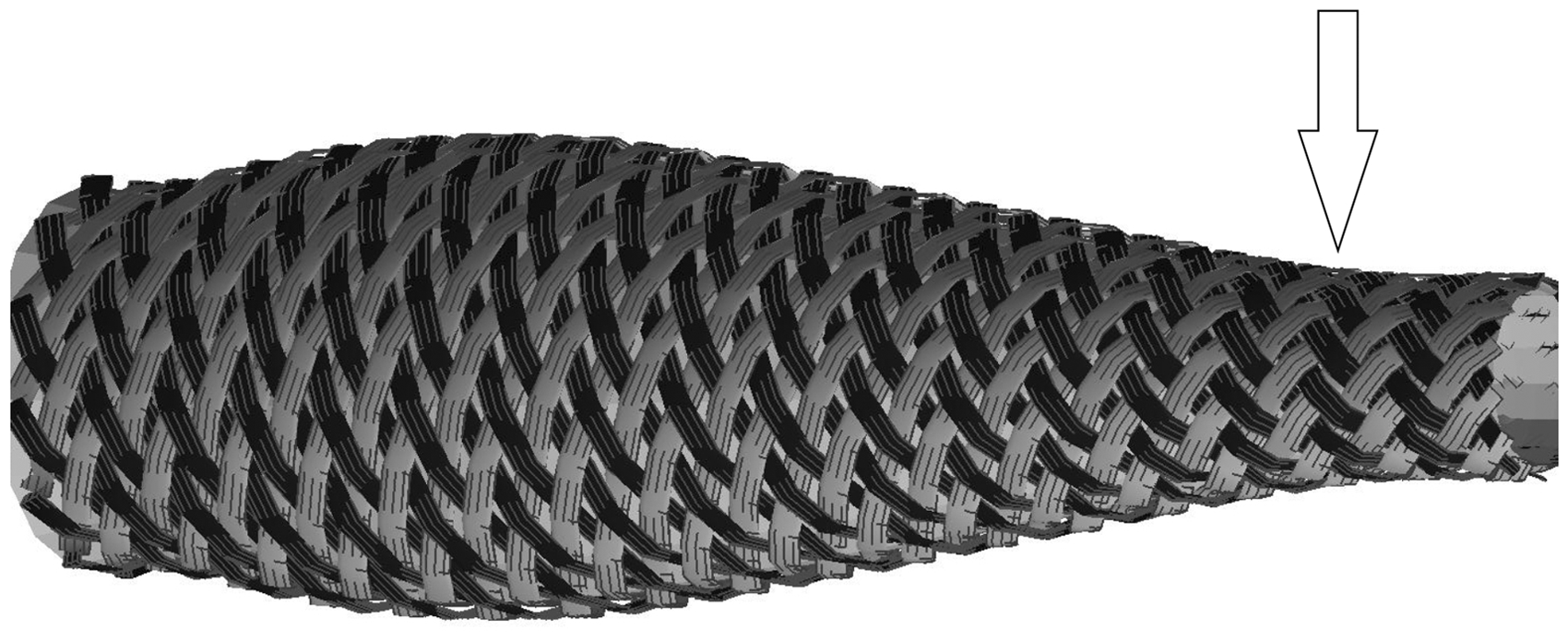
This algorithm is tested for parts that have rotational symmetry. In this case, the stability condition has to be tested once per set of crossing points with the same Z-coordinate. The geometry of braids using the elliptical cross-section of the yarns is created as presented in Figure 1.
Geometric model of the braid with a mandrel with complex form.
5
Alpyildiz
11
uses pure analytical description of the curves of the yarn path to describe the equations for the yarn undulation in detail. For a regular braid the regions of the floating are fixed to the amount of
For the ones that drive in a clockwise direction, the sign of a/2 and the phase in the sinus function regions is changed. 11
Rawal et al. 12 extend the equations for the case of a mandrel of conical cross-section and parts that consist of a combination of cylindrical and conical regions.
The above cited papers concentrate on the modeling of three main braiding structures – diamond, regular and Hercules-braided structures – covering biaxial and triaxial braids up to a floating length of three. Unit cells with arbitrary floating length can be created with Wisetex. 13 Nevertheless, it is the responsibility of the user of Wisetex to obtain the correct topology (from the braiding point of view) and the correct orientation of the unit cell into the macro geometry of the braided product. The models in Kyosev 14 represent the structures with arbitrary floating length correctly, but the explanation of how they were created is not to be found. Furthermore, the structures in Kyosev 14 do not represent braids with several yarns in a group realistically. As explained there, these have more space between the yarns and thus can be used for understanding the braid, but not to execute extended calculations.
There is as well a commercial computer-aided design (CAD) software for braiding named TexMind Braider,15,16 which seems to cover all kind of tubular and flat braided structures, including the ones with multiple yarns in a group. Public information about the models used has not been available until now.
Three-dimensional models of braids with floating length of two (regular braids)
In the modeling works of several authors1,5,11,12 appears a small mistake in the models of the regular braids only, recognizable by experienced braiders only. These cannot be produced on any “classical normal” maypole braiding machine with horn gears. The arrow on Figure 1 points to very well visible ridges that are perpendicular and not parallel to the product axis. Figure 2(a) visualizes once more schematically the orientation of the ridges in the above-mentioned papers. The visible yarn pieces, which build the visible ridges, are placed in square mesh as this is done usually during the drawing of the draft of the structure.14,17–19 In a standard machine each horn gear rotates in only one direction. All the carriers moving outside of one horn gear are building a vertical ridge, parallel to the take-off speed, which is parallel to the product axis as well (Figure 2(b)). Thus, during the analysis of the braids, the ridges are counted and their number gives the number of the horn gears. In order to produce horizontal ridges, the horn gears have to move the carriers alternating: one carrier in one direction, the other in the opposite direction, etc. (Figure 2(a)). This configuration is only possible on 3D braiding machines with individual drives of the horn gears, which are of very limited amount. It is not possible for the maypole braiding machines, due to the fact that all horn gears are connected with gears and solely move without changing the rotation direction during the production.
(a) Orientation of the ridges in some models of regular braids. (b) Proper orientation of the ridges of regular braids.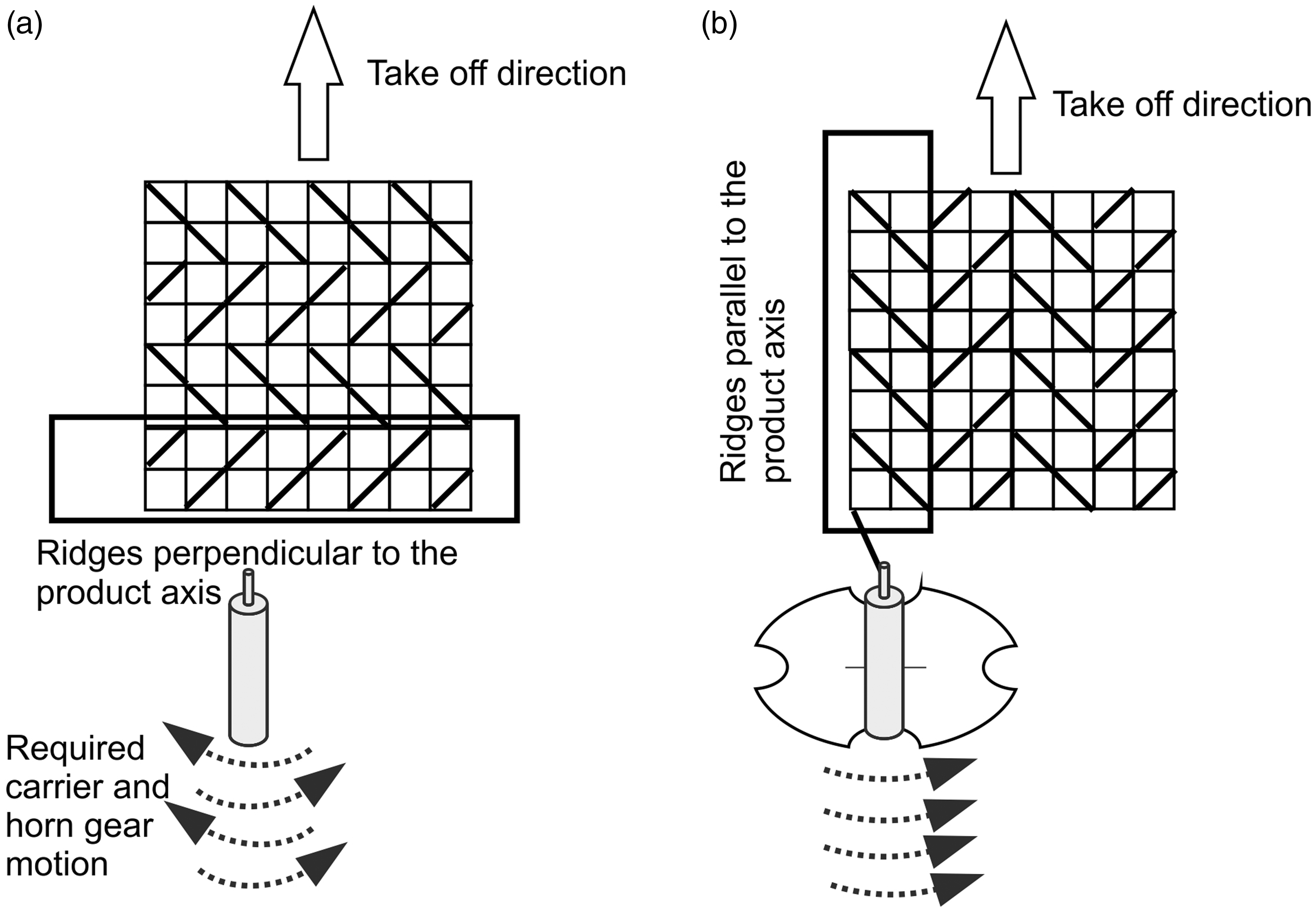
Topologically, the unit cells of both structures are equivalent, simply one structure is rotated at 90°. Technologically, a braid with unit cell A (Figure 2) is not identical to a braid with unit cell B at the macro level. The models of the structures with horizontal ridges cannot be used for color patterning of tubular braids. Furthermore, their use for mechanical calculations can lead to some differences in the mechanical behavior.
After analyzing the modeled pictures and comparing the proper yarn positions with the modeled ones, it was possible to detect the positions where the yarns were placed on the wrong side. These positions are marked and illustrated in Figure 3(a) with a thick dotted line.
(a) Lines where the yarns are modeled on the wrong side are marked with a dotted line. b) On the marked places the yarns are drawn with a blue line in their correct position. A drawn line means that the yarn is visible, not visible yarns are not drawn, or presented with a thinner line. (Color online only.)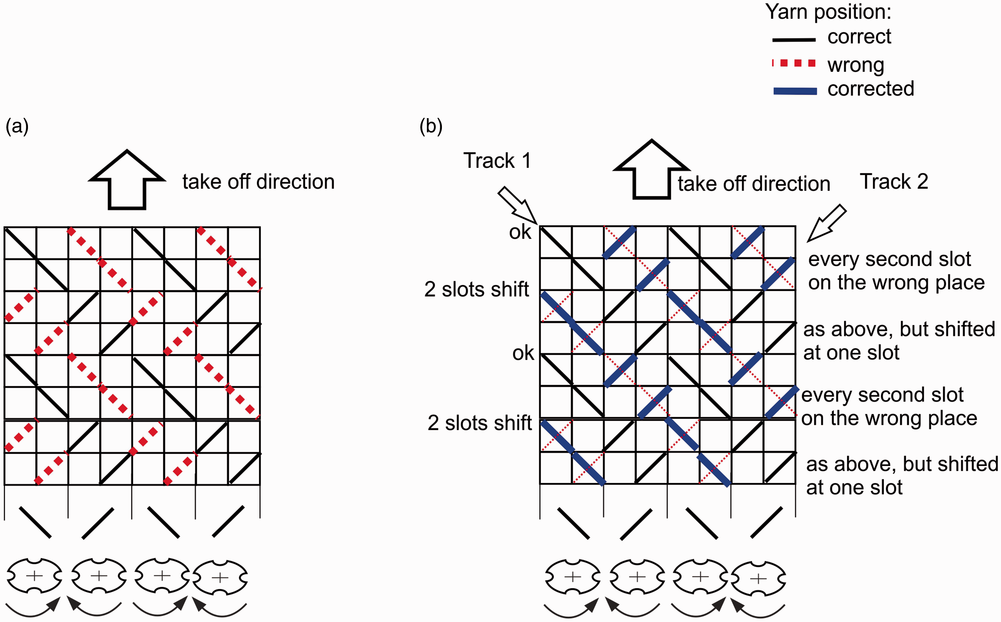
It can be seen that on track 1 (Figure 3(b)), every second yarn is placed with a phase shifting, which corresponds to the moving of the carrier on two slots around the horn gear. Counting the yarns in this track not consequently, but instead into two groups, where the second has a phase change of angle, corresponding to angle π of the horn gears, might be a possible solution for the correction of the mathematical models for the regular braids.
The yarns of track 2 (Figure 3) are once in on the correct side and once on the wrong side in their cells. Alternating as well is the starting position – one yarn is starting with proper position and one is starting with a wrong position.
Writing the correct phases and numerations of the mentioned models is not the goal of this paper, because the approach presented in the next sections is more intuitive and generalized. The aim is to present a common method for the calculations of braids with any floating length per ridge and any number of yarns in a group (= filaments in the yarn). Being independent of the braiding architecture, this method allows implementation in industrial software as it is not limited to one or other type of braid.
Generalized model for yarn path of a braid with arbitrary floating length
For this model is considered a part of a generalized braid (tubular or flat) with ridges with different floating length (Figure 4). This part consists of five visible ridges, where the first, second and the fifth have a floating length of two, while the third ridge has a floating length of five and the forth has a floating length of one. The sequence of the floating lengths per ridge can be written as 2:2:5:1:2. The part of the machine that is used for the production of such a braid is presented in the bottom part of Figure 4, following the main braiding equation as a rule for the floating length FL:
14
Part of the braid and corresponding braiding machine for explanation of the generalized geometric model of braids.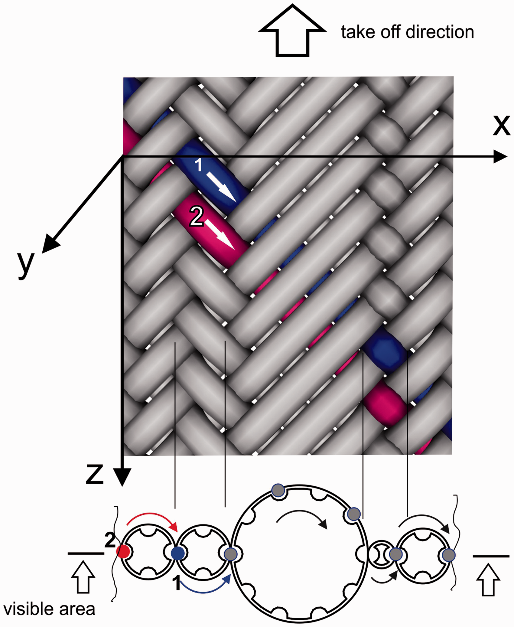
Considering the most common arrangement of 1 full 1 empty, the repeat of the arrangement is 2, so the horn gears should have 4,4,10, 2 and 4 slots for this braiding part.
Considering yarn 1 in Figure 4, it floats first (starting from z = 0) over two yarns, then under five, over one and under two. This floating corresponds to the carrier motion – the floating over each yarn corresponds to the carrier motion on the angle, equal to one segment, in the case of full occupation of the machine (full occupation means that all possible carrier positions are filled with carriers and correspond to a 1 full 1 empty arrangement along the track 14 ).
In this way for yarn 1 has to be created the same number of key points as the number of yarns in the opposite track, as all these yarns will be crossed. If the current ridge is visible, the key point has positive Y coordinate; if the ridge is hidden (the yarn is under another) then the key point has a negative Y coordinate. Each ridge with floating length of two has two key points on the same side, a ridge with a floating length of five has five points and so on. For yarn 1 the first ridge has a floating length of two, so the first two points have a positive Y coordinate; the following ridge is hidden and has a floating length of five – there are five points with a negative Y coordinate; the next ridge is visible and has a floating length of one and the last is hidden and has a floating length of two (Figure 5(b)).
Derivation of the undulation of the yarn coordinate because of the interlacement with other yarns, demonstrated on the two yarns from Figure 4. The direction Y corresponds to the thickness of the braided product.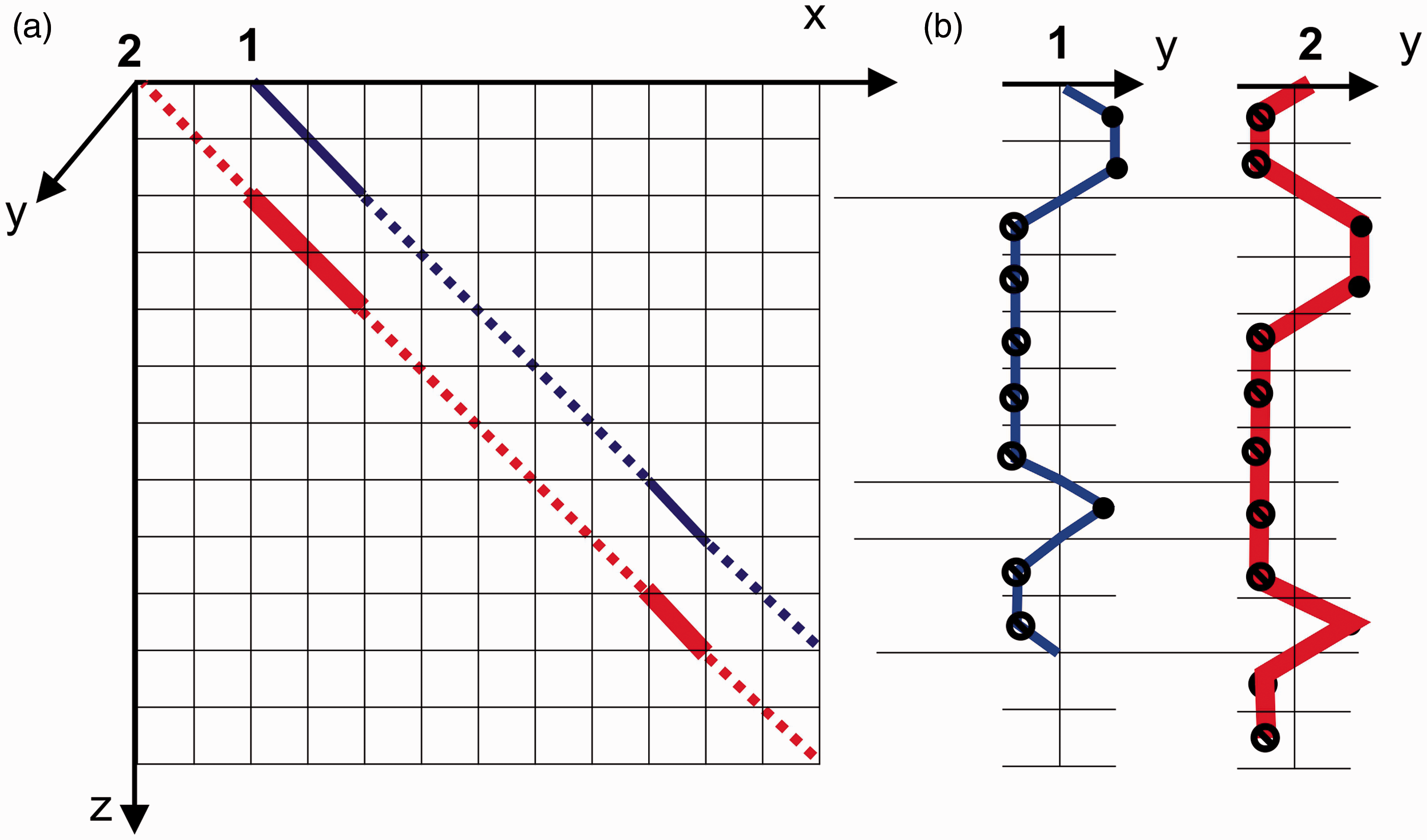
In Figure 5 it can be seen that the next yarn starts its motion with an opposite phase. Such specific rules can be derived only for specific floating lengths and not for the general case.
An algorithm for the calculation of the coordinates of the key points of a tubular or flat braid will be very similar to the algorithms for a graphical analysis of the braided structures, presented by Kyosev
14
and Engels.
19
This algorithm uses inverse braiding, which means that the horn gears are staying and the carriers are jumping from slot to slot, summarized as follows.
Initialize the braiding machine, considering the (minimal) size of the horn gears for the wished floating length of their ridges. The number of slots is stored in a vector Initialize the rotation direction of the horn gears Initialize the track(s) of this machine as a list of slots as elements T(ihg, islot), where the carrier slots in one track, denoted with their horn gear number ihg and the slot number islot, are stored. Fill the tracks with carriers according to the given carrier arrangement, for instance A = [1 0], one full, one empty. The carrier arrangement can be derived from the braiding equation. Determine which slots are currently moving the carriers, which are building visible yarn parts and which are building hidden ones. The connection line between the horn gear centers can be used as the visibility limit. Create the mesh of cells in a manner that provides every two slots of one horn gear corresponding to one column. The mesh size – defined by cell height and cell length – is easily determinable by using the number of yarns in the braid, the width or the diameter of the braid and the braiding angle.
14
For each carrier: go through its track and get the X and Z coordinates of the corresponding cells. If the current slot is visible, set the Y coordinate to +a, if it is not visible to –a, and in case of a turning cell (for flat braids) to zero. The variable a can be adjusted depending on the used model for the yarn cross-section and depending on the type of the braid – bi- or triaxial. For triaxial braids the yarn configuration of the inlay yarn has to be considered in the variable a.
For flat braids the x coordinate remains on the same plane and for tubular braids it has to be rolled over a cylinder surface, using it as a counter variable for the division of the central angle.
Any refinements about the form of the curve inside the unit cell can be done by using well-known published methods referring to geometric relations or minimization of the energy of the yarn.
The described algorithm for two yarns is visualized on Figure 5. The carrier with yarn 1 moves at the beginning along the visible slots, then along five invisible slots, one visible and two invisible. The corresponding Y coordinate is presented in Figure 5(b).
Implementation
The complete algorithm is implemented in C++ programming language. A Graphical User Interface for editing the properties of the braids is created with the wxWidgets library 20 and the main sample data is stored as Extensible Markup Language (XML) files. The images are rendered using Visualization Toolkit VTK.
Model results
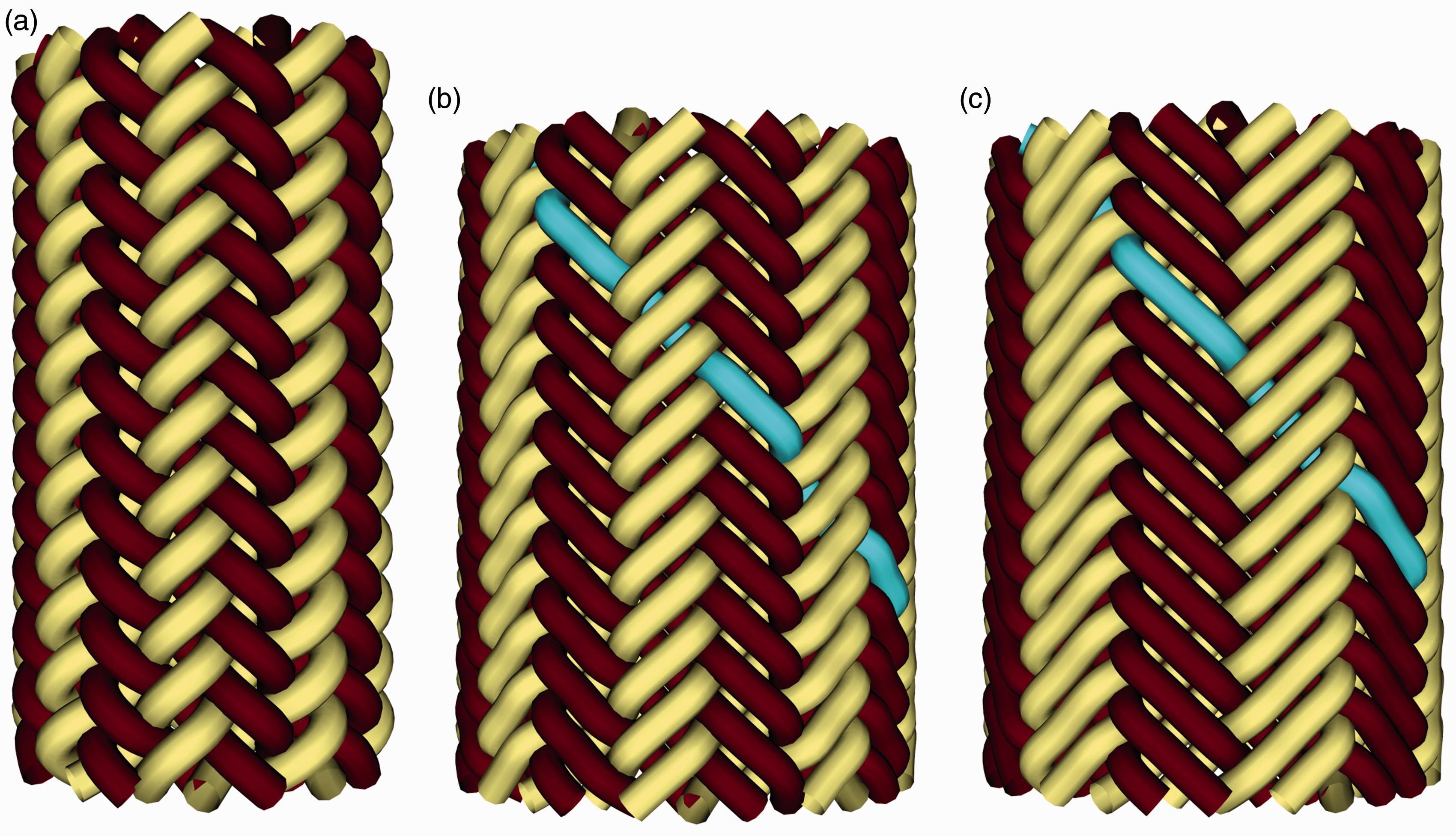
Figure 6 presents modeled flat braided fabrics with 3, 5 and 13 yarns and a floating length of one; Figures 7(a) and (b) illustrate flat braids with floating lengths of two and tree. The fancy braid, modeled in Figure 7(c) is used often as an accessory made from leather and consists of ridges with changing floating length 2:3:2:6:6:2:3:2. Tubular braids with floating lengths of 2, 3 and 4 and well-visible vertical ridges are presented in Figure 8. The braids with floating lengths of 3 and 4 in this figure are not common for rope production, but are becoming more so because they provide less fiber crimp, which is important for carbon and glass fibers, for instance.
Simulated flat braids with (a) 3, (b) 5 and (c) 13 yarns in pattern 1:1-1 (floating length one, one yarn in a group). Flat braids with floating lengths of (a) 2 and (b) 3 and fancy braids with ridges with different floating lengths – sequence 2:3:2:6:6:2:3:2. Tubular braids with floating length (a) 2 (regular braid), (b) 3 and (c) 4.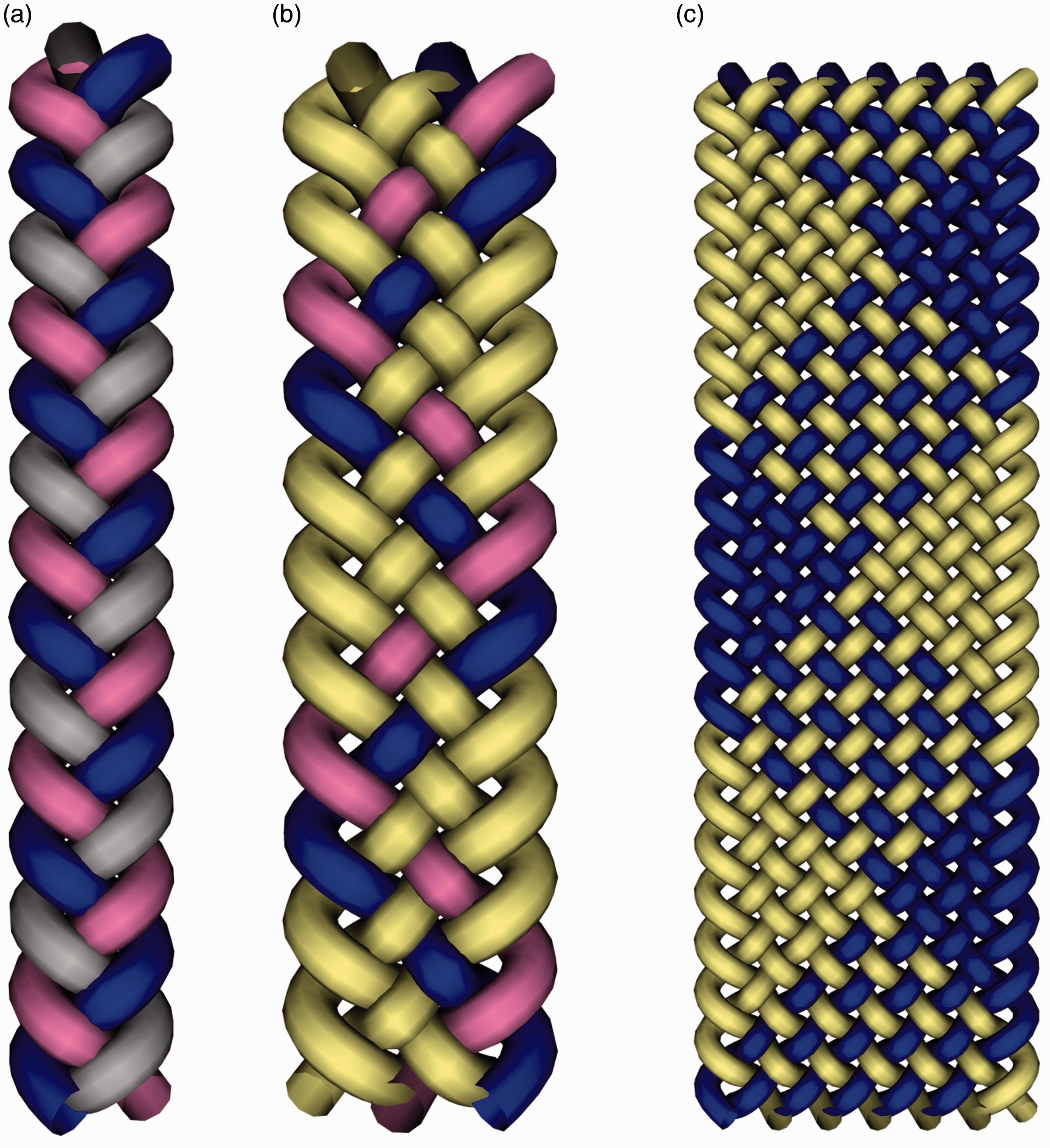

Extension to multifilament models
Once the yarn paths of the braid are calculated, multiple filaments in each yarn can be added, as all these work as a group. For each point of the yarn paths a modified 1 Frenet frame t,p0,q0 is generated and saved, which defines the orientation of the yarn in the untwisted state. Rotating the modified normal and binormal (p0,q0) around the tangential vector at each point to an angle γ, a twist to this cross-section can be applied. For each single filament of the cross-section a set of coordinates of their centers ci is defined and oriented according to the orientation of the p-q vectors of this cross-section (Figure 9). In this way different configurations of multifilament yarns can be created – with flat, circular, elliptical and any other cross-section. Some aspects about the orientation of the yarn cross-section under consideration of its geometrical moment of inertia can be found in any book about strength of materials or with some yarn considerations, for instance in Kyosev, Angelova and Kovar. 21
Simulation results of the multifilament models
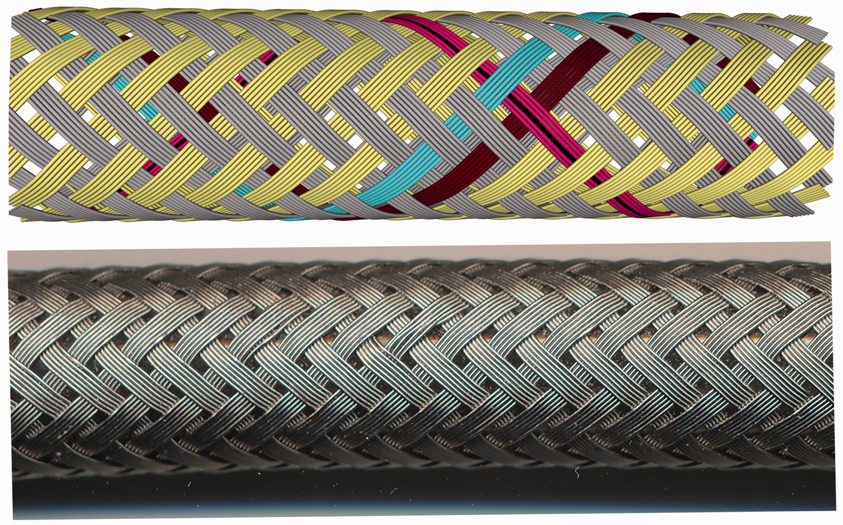
Figure 10 presents a modeled tubular braid with floating length of two and six wires in each group and the photo of such a braid from the water hose, from which it is possible to see that the simulated geometry is very close to the real one. Figure 11 presents another tubular braid with floating length of three and for wires in a group, and three regular braids (floating length of two) with six filaments distributed on the circular yarn cross-section with no twist (Figure 11(b)), twist 200 m–1 in the S and Z directions for each track (Figure 11(c)) and for 400 m–1 (Figure 11(d)). The geometry of the single filaments can be a good starting point for extended mechanical calculations.
Principle of calculation of the points of the single filaments. Tubular braid with a floating length of 2 (regular braid) and six wires in a group, used for water hose reinforcement as a simulation, and a photo. Tubular braids as multifilament models: (a) structure 3:3-4 (floating length of three, four yarns in a group), without twist in flat arrangement; (b) regular braid (2:2-1) with six filaments on the yarn surface without twist; (c) the same as (b) but with 200 m–1 in S and Z twists of both tracks, respectively; (d) same as (b) but with 400 m–1 in S and Z twists of both tracks, respectively.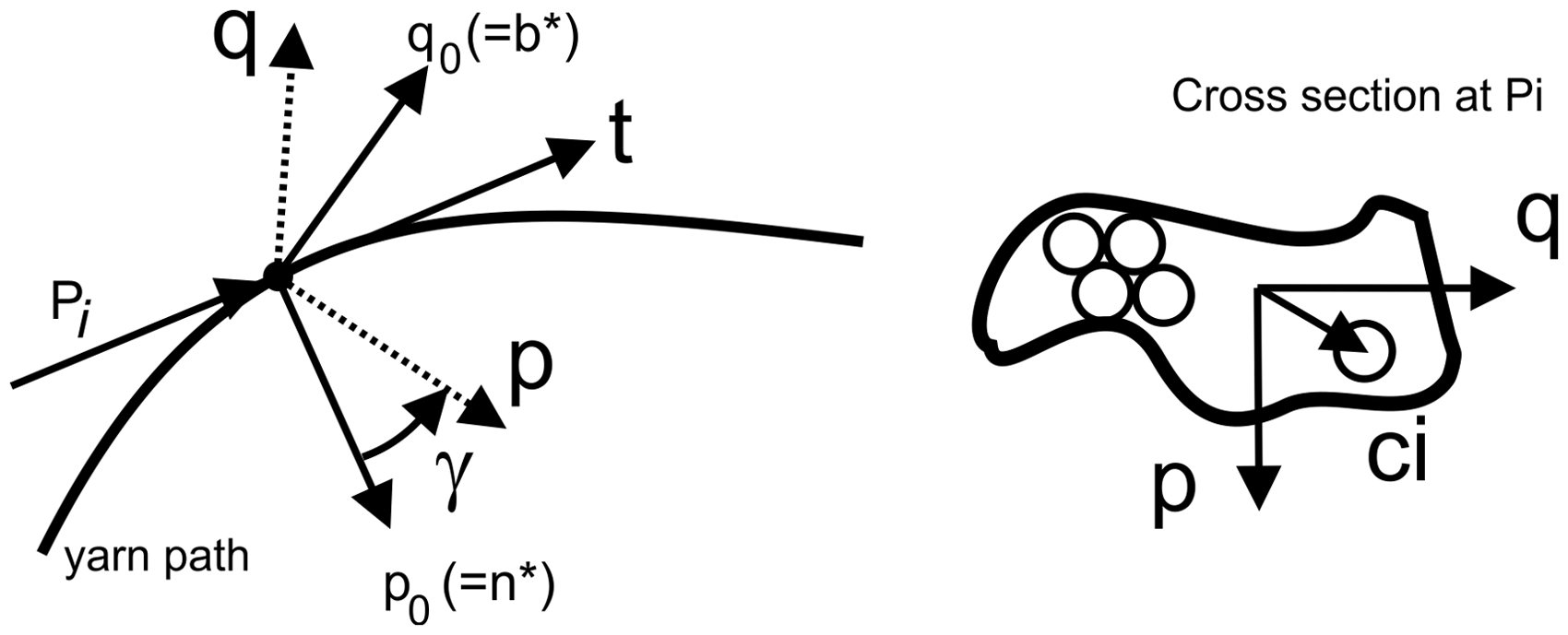

Discussion
The presented method allows quick and stable generation of the geometry of the tubular and flat braided structures with intuitive connection of the input data and algorithm to the real braiding machine and process. This reduces the risk of errors of the model, but requires extended understanding of the braiding process, which is not always the case for persons who are able to develop mathematical models and vice versa.
The described method concentrates only on the definition of several important key points of the yarn path. If only these points are used, the models are of small size and computational shorter time. The accuracy of the path between these points is reduced as well, because these paths are approximated with polynomials and no geometric or mechanic rules for contact are applied there. Pure geometrical contact detection and removal algorithms can be applied in these places, but in such a case the curves can lose their smoothness and in some cases are even less accurate than the not corrected curves. Really meaningful improvement of the accuracy of the models can be achieved only if the complete mechanical data of the yarns is used and some kind of mechanical equilibrium is reached, as for instance the implemented algorithms in the software Wisetex. 13 Such a development is actually no longer in the scope of geometrical modeling and is beyond the limits of this paper.
Conclusions
The critical overview of the works about the geometrical modeling of braided structures pointed out a small inaccuracy of some existing models for the special case of regular braids. This inaccuracy is explained and, furthermore, a way for its correction is presented. A generalized model for the calculation of the yarn paths of tubular and flat braids, using the knowledge of the braiding process, is presented and tested on several different braided structures. One of them is optically compared with a real structure. The concept of the extension of the algorithm for a multifilament model is given and tested on braids with flat and circular distribution of filaments with and without twist.
Footnotes
Declaration of Conflicting Interests
The authors declared no potential conflicts of interest with respect to the research, authorship and/or publication of this article.
Funding
The authors received no financial support for the research, authorship and/or publication of this article.