
Abstract
Glass-fiber felts have emerged as a popular material for noise reduction. This paper investigates the effect of various morphologies (micro-layer, macro-layer and air-layer) of glass-fiber felts on sound insulation. The sound transmission loss is measured by a Brüel & Kjár (B&K) impedance tube. The results show that the sound insulation of glass-fiber felts can be improved by increasing the number of macro-layers. The comparison between the macro- and micro-layer of glass-fiber felts on sound insulation is systematically carried out. Notably, the sound transmission loss of glass-fiber felts with similar areal density and thickness favors macro-layer structures over micro-layer structures. A simple model is established to explain this phenomenon. In addition, the sound transmission loss exhibits period fluctuations due to the presence of the air-layer between glass-fiber felts, which can be theoretically explained by the resonance effect. It is found that sound transmission loss can be improved by increasing the number of air-layers.
With the development of modern industry and traffic systems, noise has become a growing problem to human health. 1 Fibrous materials which can convert sound energy into heat energy have been used as popular noise insulation materials. Various properties of fibrous materials such as the density, thickness, fiber type, finishing methods and air flow resistivity have influence on the acoustic performance. 2
Boock et al. 3 proposed an aircraft fuselage structure in which glass wool mat was used as the sound insulation material. Sun et al. 4 explored the sound absorption performance of recovered fiber glasses (RFG) from waste printed circuit boards. It was found that RFG had excellent sound absorption over a broad-band frequency range and could be used as a potential alternative for commercial sound absorption. Delany et al. 5 explored the acoustical properties of fibrous absorbent materials and found that density and air-flow resistivity affected the absorption coefficient. Yang et al. 6 investigated the sound-absorbing behavior of fiber assemblies. The results showed that a fiber assembly with lower fiber density and smaller fiber average diameter led to better sound absorption performance. Tascan et al. 7 explored the effect of fiber denier and fiber cross-sectional shape on acoustical behavior of vertically lapped nonwoven fabrics. Fabrics made from three denier fibers were better sound insulators than those made from 15 denier fibers for three different fiber shapes (round, trilobal and 4 deep grooved). Li et al. 8 studied the effect of shear thickening fluid on the sound insulation of textiles. The sound insulation performance of the shear thickening fluid treated fabrics was superior to that of the untreated fabrics and their sound insulation level improved with increased surface density. Yang et al. 9 investigated three types of glass-fiber felt sandwich structures to identify the optimal sound insulation structure. The mass–porous–mass sandwich structure had the highest sound transmission loss (STL). Kim et al. 10 presented sound absorbing structures that were constructed using multiple layers of fibrous paper. The acoustic properties changed depending on the thickness of the air cavity between the thin layers and porosity of the layers. Liu et al. 11 found that smaller pore diameter or greater porosity yielded better sound absorption at low frequency for fiber nonwoven fabrics, and the sound absorption at low frequency further increased as the back cavity depth increased. Castagnede et al. 12 found that the absorption properties were decreased during the compression of a fibrous mat. Ersoy et al. 13 investigated the sound absorption properties of industrial tea-leaf-fiber. The experimental results indicated that a 1 cm thick tea-leaf-fiber with backing provided sound absorption almost equivalent to that of six layers of woven textile cloth. Na et al. 14 found the structure of micro-fiber fabrics was important for controlling sound absorption, and the density of fabric had more effect than fabric thickness and weight on sound absorption.
As can be seen above, most researchers have focused on the sound absorption and sound insulation of fibrous materials from the perspective of material, material structure or finishing methods. However, the effect of morphology on the sound insulation of glass-fiber felts has not been investigated before. The objective of this study is to investigate the sound insulation of glass-fiber felts with different morphologies (micro-layer, macro-layer and air-layer). All the samples were produced by the flame blowing process (FBP). Micro-layer glass-fiber felts were formed directly by FBP whereas macro-layer glass-fiber felts were constructed by stacking up multiple layers of thin glass-fiber felts. Additionally, the effects of thickness and the number of air-layers on sound insulation are explored. The underlying mechanism is discussed.
Experiments
Materials and fabrication
Glass-fiber felts were produced by the FBP shown in Figure 1. This method includes the following steps: glass balls are melted in a furnace and vitreous fluid flows out from a die plate. They are then drawn into primary filaments of diameter 150–250 µm by means of drawing rollers. These primary filaments are immediately exposed to a hot-air current jetted from a nozzle which causes them to melt. The molten material is blown out into a flame fiber of diameter ≤2 µm.15,16 Phenolic resin adhesive is sprayed before the glass fibers reach the perforated mesh. Finally, glass fibers with phenolic resin adhesive are sent into a curing furnace where glass-fiber felts are formed.
Flame blowing process.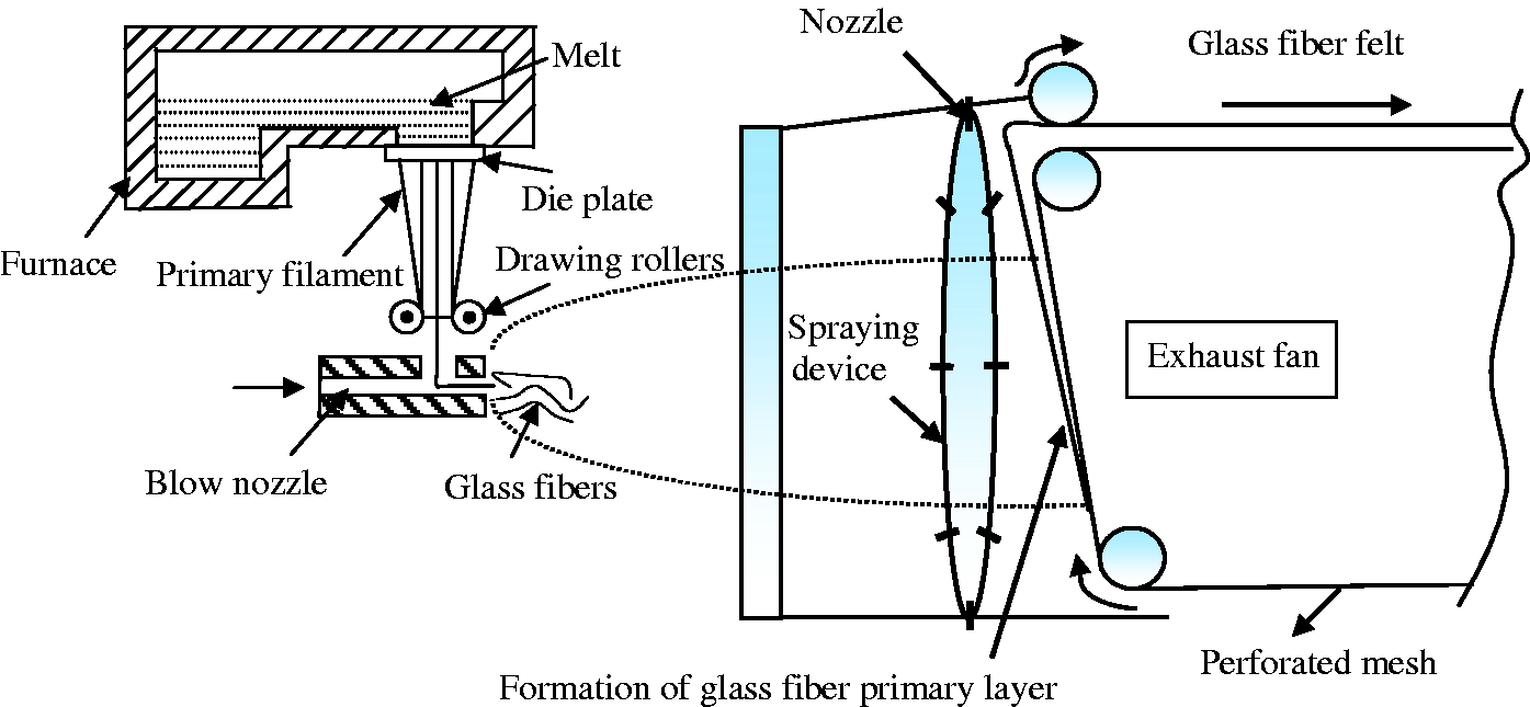
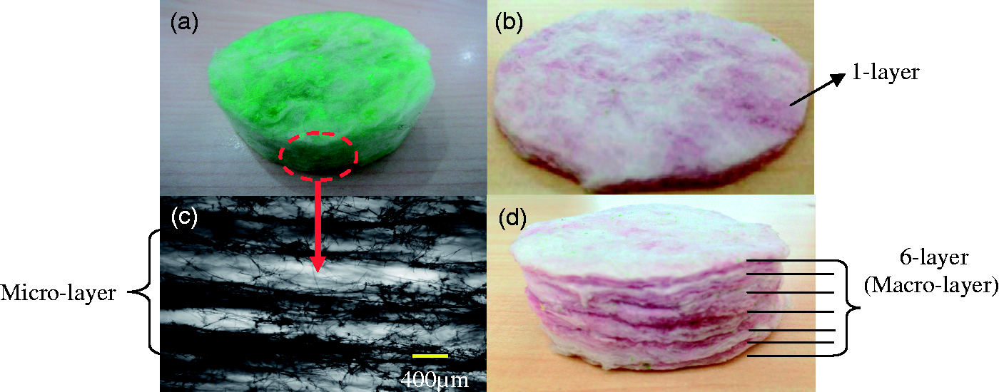
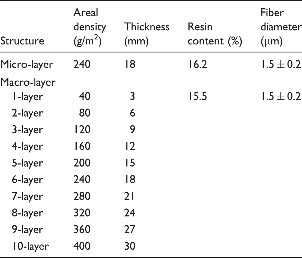
The raw materials were glass balls and phenolic resin adhesive. The resulting samples were comprised of pure glass fibers and phenolic resin adhesive. The energy dispersive spectrometer (EDS) pattern of glass balls is shown in Figure 2. The main elements of glass fiber are Si, O and Na, with traces of Mg, Al, K, Ca and Fe. Although the chemical composition of the glass fiber can affect the STL by changing the density, its effect is not investigated in this paper. Table 1 provides a list of structural parameters. The first line shows the parameters for a single micro-layer and the following lines are for multi-layer glass-fiber felts with different layer numbers (macro-layer structure). As can be seen, six-layer (macro-layer) glass-fiber felts have the same thickness as a single layer of micro-layer glass-fiber felt. The main difference is the interface between each two layers of the macro-layer structure, which will be shown to have a significant impact on sound insulation. The multi-layer structures (micro-layer and macro-layer) of glass-fiber felts are illustrated in Figure 3.
(a) Glass balls. (b) The energy dispersive spectra. The structures of glass-fiber felts: (a) a single layer of micro-layer glass-fiber felt; (b) one-layer (macro-layer) glass-fiber felts; (c) morphology of the micro-layer glass-fiber felt; (d) six-layer (macro-layer) glass-fiber felts. Glass-fiber felts produced by FBP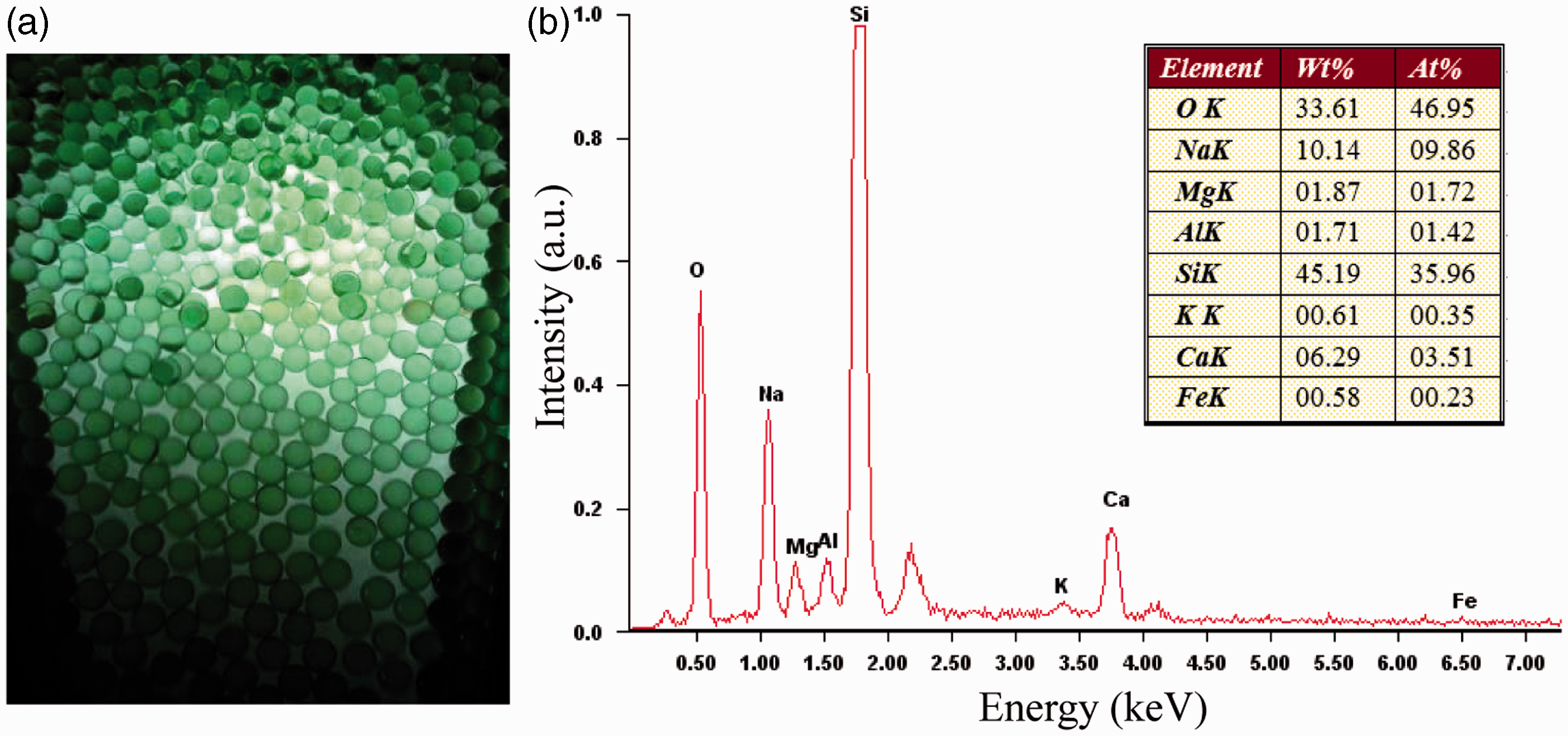
Material characterization and sound insulation measurement
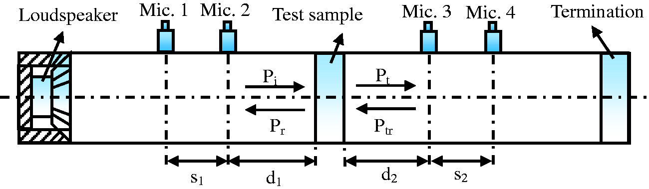
The cross-sectional structures of various glass fiber felts were investigated by the optical microscope (BD-200). The chemical composition of the glass balls were examined by EDS (Genesis 2000XMS 60). The STL was measured by a B&K impedance tube conforming to the ASTM (American Society for Testing and materials) E2611-09 standard. The apparatus is shown in Figure 4. The microphones were placed at the four corresponding different positions along the B&K impedance tube. The diameters of the tube and testing samples were 29 mm. The STL can be calculated using the pressures captured by the four microphones and the transfer matrix formulation.
17
The acoustic measurements were carried out in the frequency range of 300–6400 Hz. All samples were tested at a temperature of 23℃ with humidity around 40%.
Scheme of measuring STL with a B&K impedance tube.
Results and discussion
There was a strong correlation among noise insulation, glass-fiber felt structures and the frequency of sound. Glass-fiber felts with different structures could show distinctive STL at different frequencies.
Sound insulation of macro-layer glass-fiber felts
The STL characteristics can be divided into two distinct regions for normal incidence (the sound-ray path is normal to the surface): at low frequencies (typically below 200 Hz), the STL is controlled by the stiffness and resonance of materials; afterwards, the STL of the material is governed by the areal density (mass per unit area) and can be improved by increasing the mass (typically above 200 Hz). 18
STLs of macro-layer glass-fiber felts with various layers are shown in Figure 5. The number of layers was increased from one to 10 with an increment of one. At frequencies below 1.7 kHz, the acoustic insulation first fluctuated and then gradually increased. This was possibly because the STL was predominately controlled by stiffness and resonance in low frequencies. In the 1.7–6.4 kHz range, STL was controlled by the surface density and structure of fibrous materials. The mass law states that the transmission of the noise through a material is inversely proportional to the areal density. Due to the mass law, samples with more layers showed higher STLs. In addition, multi-layer glass-fiber felts yielded a higher amount of acoustic reflection between layers and could potentially cause more frictional heat from sound energy. This may also contribute to the higher STLs as the number of layers increased.
STLs of macro-layer glass-fiber felts.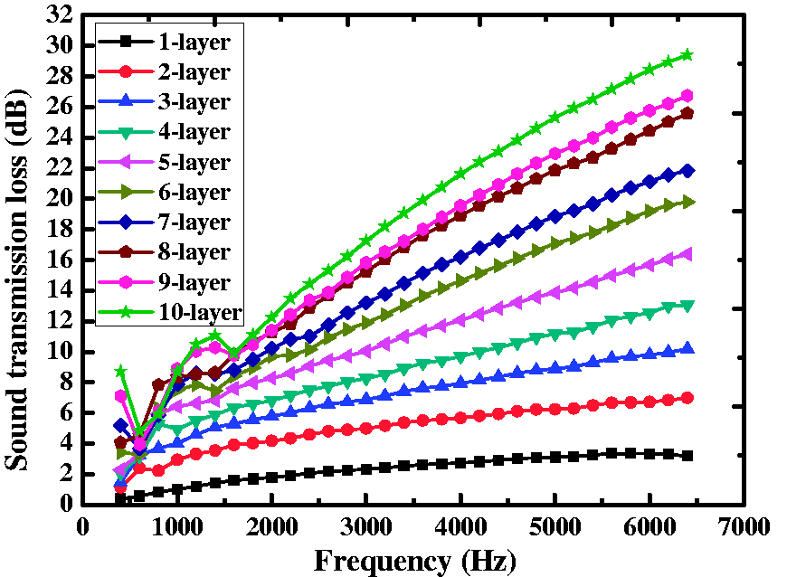
Since humans are more sensitive to sound in the 500–4000 Hz range,
19
STLs of multi-layer glass-fiber felts are compared at 500 Hz, 1 kHz, 2 kHz, 3 kHz and 4 kHz, as shown in Figure 6. The improvement of STL with increased number of layers was more pronounced at the highest frequency, i.e. 4 kHz, indicated by the steep slope of the curve. This was expected since fibrous materials typically perform better in terms of acoustic absorption at high frequencies.
STLs of macro-layer glass-fiber felts at different frequencies.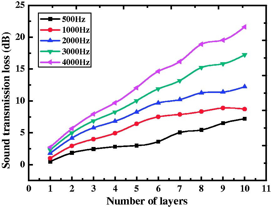
Comparing glass-fiber felts with micro-layers and macro-layers
The STLs for six-layer macro-layer glass-fiber felts and a single layer of micro-layer glass-fiber felts are shown in Figure 7. The macro-layer one exhibited higher STL than that of micro-layers over the entire tested frequency range even though they had the same thickness and areal density. The advantage of the macro-layer structure was particularly clear at frequencies above 1.5 kHz. At the highest tested frequency, the STL difference reached the maximum at around 10 dB.
STLs of glass-fiber felts with micro-layer and macro-layer structures.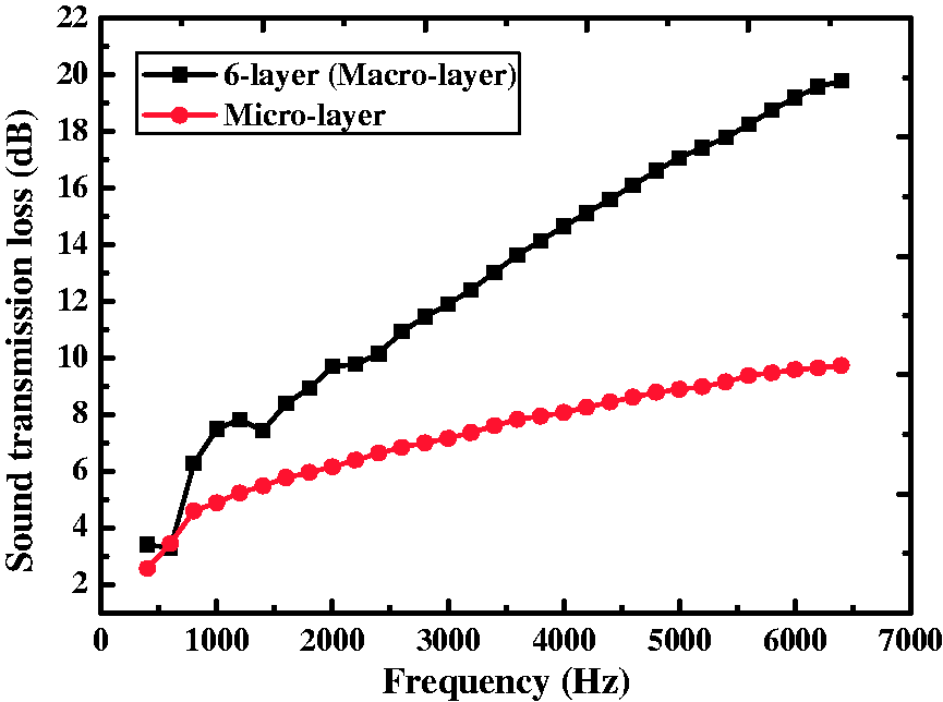
The macro-layer structure could be described as a multi-layer acoustic absorber, which can be analyzed by a simple model (mass–air–mass) as shown in Figure 8(a). Figure 8(b) illustrates the model of the micro-layer structure, which can be seen as consisting of a number of “three-layer” structures, i.e. dense (more fibers)–loose (less fibers)–dense structure.
20
Looking at the macro-layer structure, as sound enters the glass-fiber felts, part of the energy translates to vibrational and heat energy and others (that is not absorbed by glass fiber felt) continue to diffuse and propagate. The relatively large mismatch between the characteristic acoustic impedance of the mass-layer and air-layer causes multiple reflections, which leads to a longer path of the sound in the absorbing material and therefore more effective sound absorption. On the other hand, micro-interfaces are formed by dense layers (more fibers) and loose layers (less fibers). In other words, the change of density leads to the formation of micro-interfaces, which are on a much smaller scale compared with that of macro-interfaces. The impedance mismatch is also smaller, indicating fewer acoustic reflections. These could partially explain why the macro-layer structure could yield better STLs.
Structure model of (a) macro-layer structure (b) micro-layer structure. The arrow with two lines crossing it indicates the direction of the sound wave.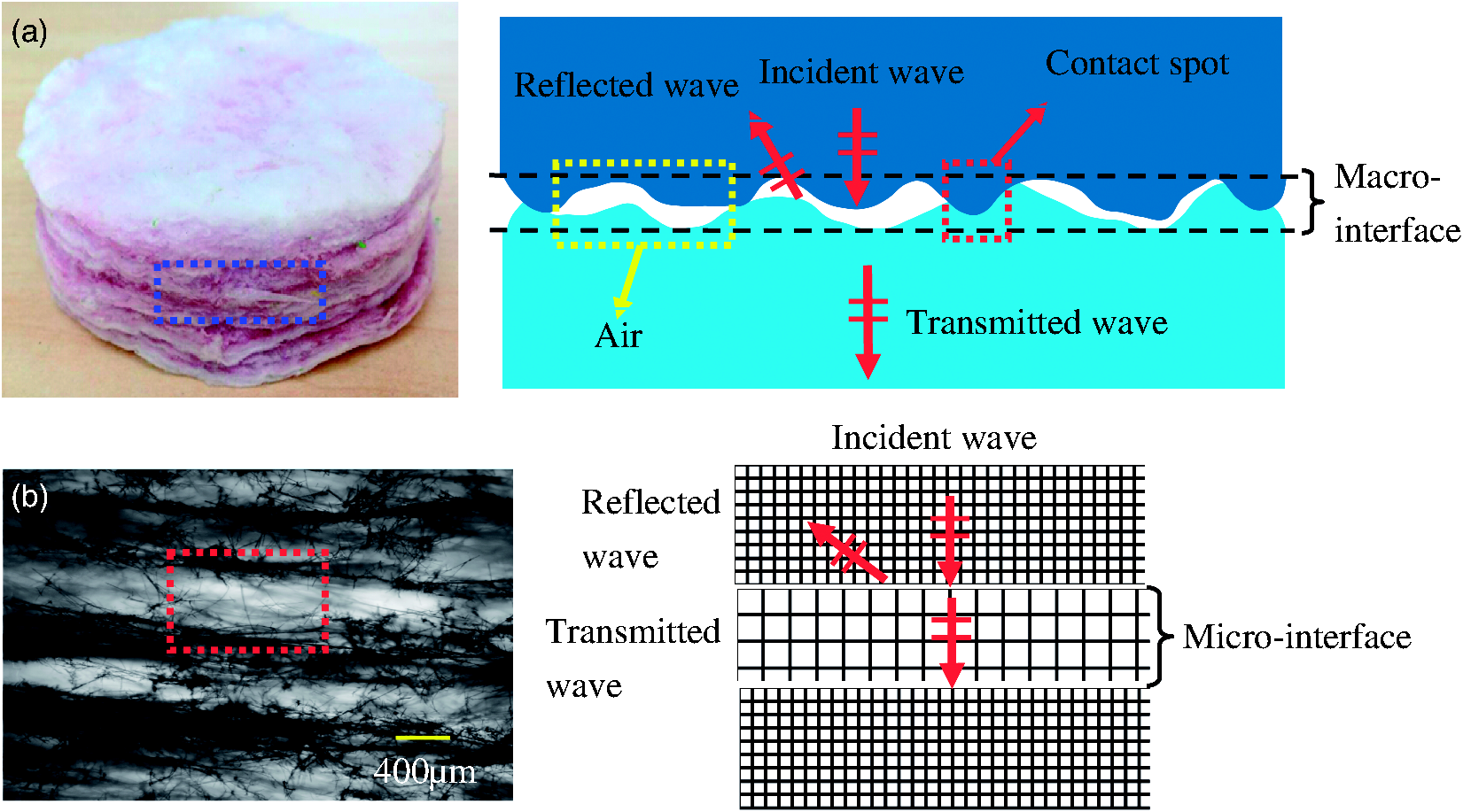
The existence of macro-interfaces and micro-interfaces led to different STLs which are shown in Figure 9. Sound insulation of three-layer (macro-layer) glass-fiber felts was equivalent to that of a single layer of micro-layer glass-fiber felts (seen in Figure 9(a)). Micro-layer glass-fiber felts were also stacked up/superposed to obtain composite structures (double and triple) for enhanced transmission loss. For double micro-layer glass-fiber felts, the STL fell in between the curves of five-layer and six-layer glass-fiber felts (macro-layer) (seen in Figure 9(b)). Under 3.5 kHz, the STL was close to the six-layer structure. With the increase of frequencies, the STL gravitated toward that of the five-layer structure. A similar phenomenon was seen for triple micro-layer glass-fiber felts: the STL at low frequencies was similar to that of the 10-layer structure, whereas at higher frequencies the result approached that of the nine-layer structure (seen in Figure 9(c)).
STLs of different micro-layer and macro-layer structures.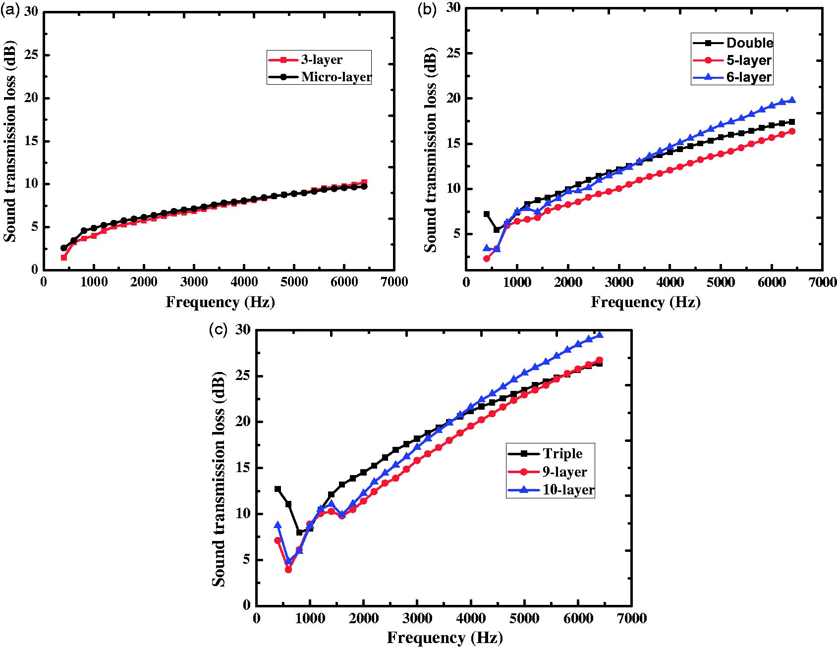
The result indicates that macro-interfaces improve the sound insulation property of glass-fiber felts. Glass-fiber felts with macro-interfaces have higher values of STL than those with micro-interfaces. The reason for this is possibly that the interfaces cause reflections between layers, therefore enhancing the absorption of the glass-fiber felts and that the reflection caused by macro-interfaces is stronger than by micro-interfaces.
The effect of air-layers on the sound insulation
Thicknesses of air-layers and glass-fiber felts
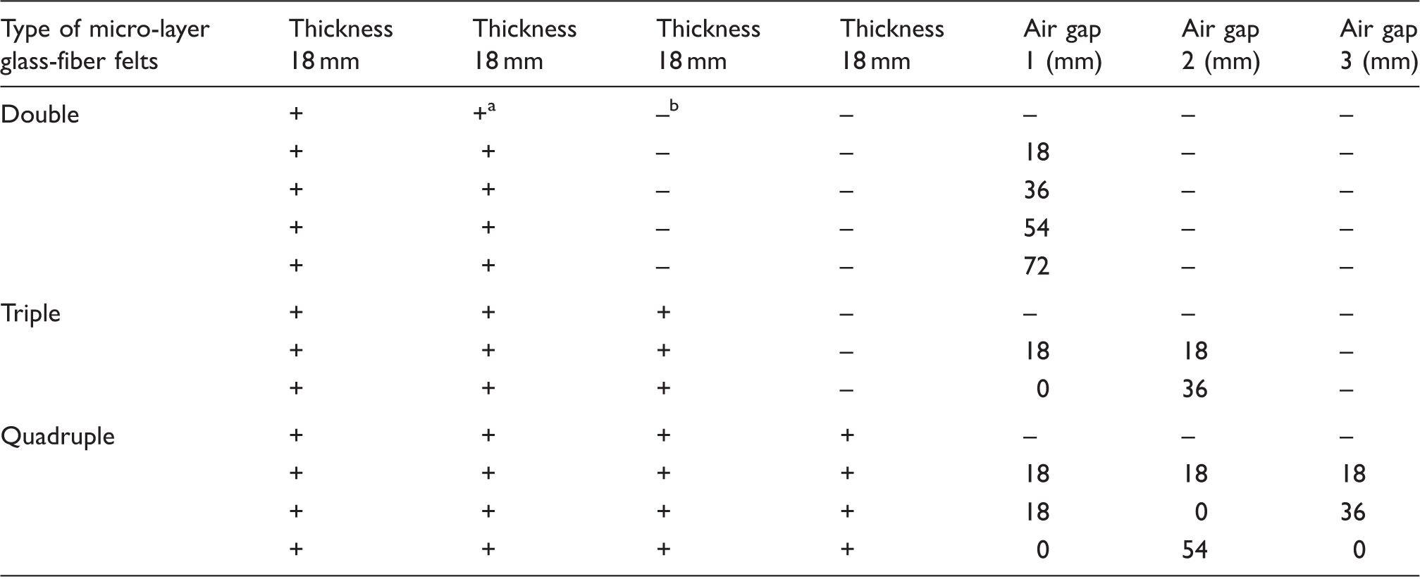
+a use; –b not used
STL of double glass-fiber felts with different air-layers
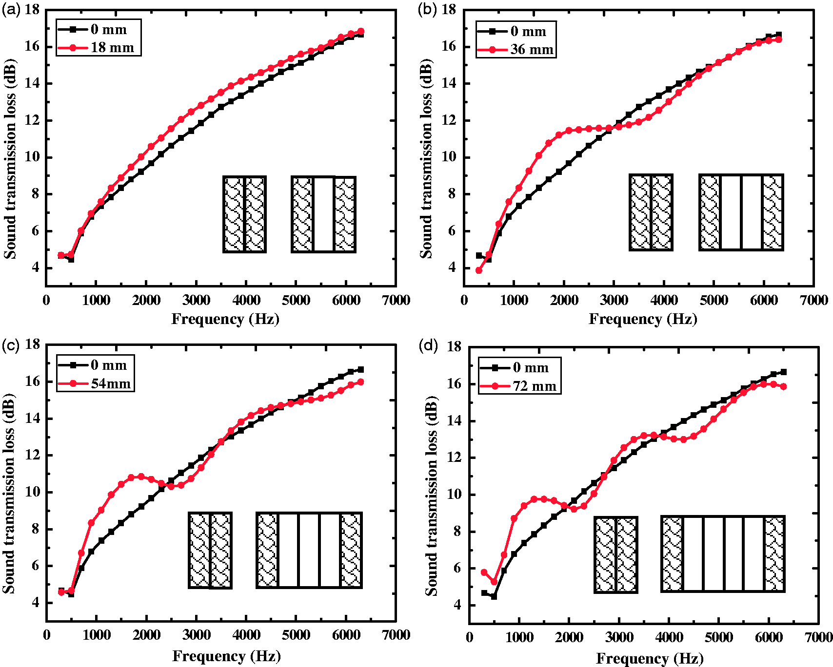
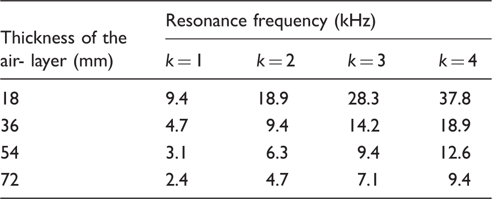
The effect of the distance (air-layer) between two micro-layer glass-fiber felts (double) was first assessed. For the double glass-fiber felts, the thicknesses of the air-layers were 0 mm, 18 mm, 36 mm, 54 mm and 72 mm. The effect of an air-layer on STL and the corresponding composite structures is shown in Figure 10. The results indicated that the air-layer had an impact on the STL of the glass-fiber felts. For double micro-layer glass-fiber felts with the air-layer thickness at 18 mm, the STL was improved by 1–1.5 dB in the 1.5–5 kHz range. Then, the thickness of the air-layer was increased with an increment of 18 mm. It was found that the STL exhibited period fluctuations. The greater the thickness of the air-layer, the more the STL fluctuated. A possible explanation is that successive reflections might occur due to the existence of air-layers and resonant modes could arise. The resonant frequencies can be estimated by
21
STLs of double glass-fiber felts with different air-layer thicknesses: (a) one air-layer; (b) two air-layers; (c) three air-layers; (d) four air-layers. Calculated resonance frequencies
STL of triple and quadruple glass-fiber felts with different air-layers
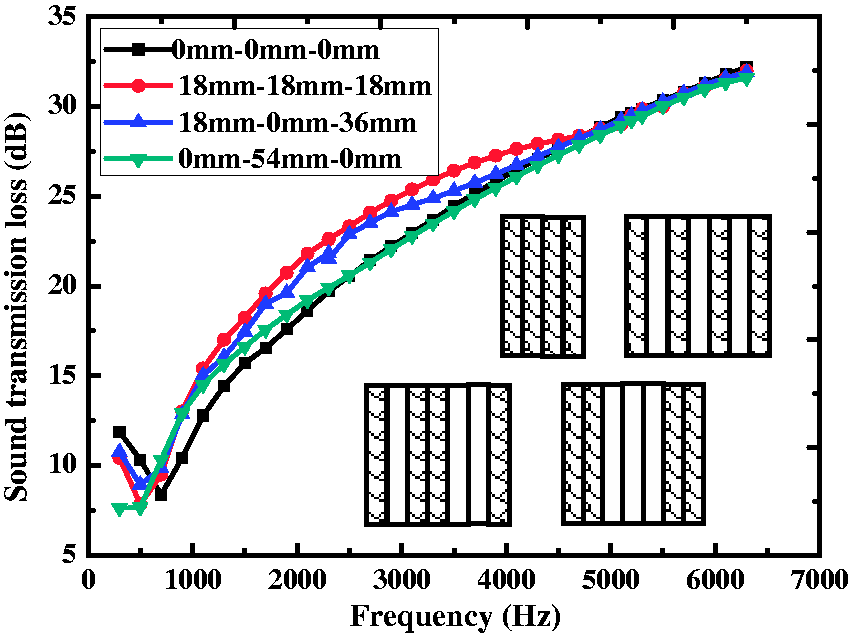
For the triple glass-fiber felt composite structure, the thicknesses of the air-layers were 0 mm–0 mm, 18 mm–18 mm and 0 mm–36 mm. The corresponding STLs and composite structures are shown in Figure 11. When increasing the number of air-layers, STLs of the composite structure were improved at frequencies below 6 kHz. In other words, STLs of the 18 mm–18 mm structure were the highest, followed by that of the 0 mm–36 mm structure. The 0 mm–0 mm structure had the worst performance. However, all three curves converged at high frequencies, i.e. after 6 kHz. This is probably because at low and mid frequencies, where sound absorption is less effective in each layer, a higher number of air-layers will introduce a higher amount of reflection on the boundaries, leading to a longer path of sound in the absorbing material and therefore more absorption. At higher frequencies, since the absorption in each layer is already sufficiently effective and there are fewer reflections on the boundaries, more air-layers will not lead to significantly higher absorption or STL. This phenomenon was also seen in quadruple glass-fiber felts with different air-layers. The STLs and composite structures are shown in Figure 12. The optimal structure was 18 mm–18 mm–18 mm, which had the largest number of air-layers. All curves converged again at high frequencies above 6 kHz. For the triple glass-fiber felts in the 0 mm–36 mm case, although the resonance mode would occur at around 4.7 kHz, the STL dip was not observed. This could be because the glass-fiber felts were thicker (there was a two-layer micro-layer glass-fiber felt) and the corresponding higher absorption counteracted the resonance effect. The same argument could be used to explain why resonances were not observed in one of the quadruple glass-fiber felts cases (i.e. 0 mm–54 mm–0 mm).
STLs of triple glass-fiber felts with different air-layers. STLs of quadruple glass-fiber felts with different air-layers.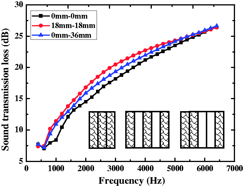
Conclusions
In this paper, sound insulation of multi-layer glass-fiber felts is experimentally investigated. STLs of glass-fiber felts with macro-layer structure are better than those of micro-layer structure under the same thickness and areal density. This is possibly due to the stronger reflections between macro-layer glass-fiber felts. Single layer, double layers and triple layers of micro-layer glass-fiber felts are compared to multi-layer macro-layer glass-fiber felts. STLs of these micro-layer glass-fiber felts are found to be equivalent to those of three-layer glass-fiber felts, five- or six-layer glass-fiber felts, and eight- or nine-layer glass-fiber felts, respectively. In addition, STLs of glass-fiber felts can be changed by varying air-layers. The existence of air-layers leads to resonance modes which can be observed as the dips in the STL curves. The thicker the air-layer, the more resonance modes can be seen in the tested frequency range. Finally, the STL at frequencies below around 6.0 kHz is improved by increasing the number of air-layers.
Glass-fiber felts are popular products on the market for noise reduction in buildings and aircrafts. Glass-fiber felts with a macro-layer can potentially achieve excellent sound insulation performance with light weight and small thickness, therefore maximizing the use of space in buildings and minimizing the weight of aircraft. For the air-layer, we should choose the air-layer thickness according to the requirements of sound insulation and avoid the resonant frequencies.
Footnotes
Declaration of conflicting interests
The authors declared no potential conflicts of interest with respect to the research, authorship and/or publication of this article.
Funding
The authors disclosed receipt of the following financial support for the research, authorship, and/or publication of this article: The authors would like to thank the financial support of Jiangsu Collaborative Innovation Center for Advanced Inorganic Function Composites and the Priority Academic Program Development of Jiangsu Higher Education Institutions. This work was also supported by the NUAA Fundamental Research Funds (grant number NO.NS2015060), Major Achievements of Jiangsu Province (grant number BA2013097) and Development of Vacuum Insulation Panel of China Building Cooperative Research (grant number 2015DFI53000).