
Abstract
To investigate the reinforcement architectures effect on the electromagnetic wave properties of carbon fiber reinforced polymer composites, three-dimensional (3D) interlock woven fabric/epoxy composites, 3D interlock woven fabric with stuffer warp/epoxy composites, and 3D orthogonal woven fabric/epoxy composites were studied by the free-space measurement system. The results showed that the three types of 3D woven carbon fiber fabric/epoxy composites had a slight difference in electromagnetic wave properties and the absorption was their dominant radar absorption mechanism. The electromagnetic wave absorption properties of the three types of composites were more than 90% (below −10 dB) over the 11.2–18 GHz bandwidth, and more than 60% (below −4 dB) over the 8–12 GHz bandwidth. Compared with unidirectional carbon fiber reinforced plastics, the three kinds of 3D woven carbon fiber fabric/epoxy composites exhibited better electromagnetic wave absorption properties over a broadband frequency range of 8–18 GHz. Therefore, the three kinds of 3D woven composite are expected to be used as radar absorption structures due to their excellent mechanical properties and outstanding absorption capacity. The total electromagnetic interference shielding effectiveness of the three types of 3D carbon fiber woven composites are all larger than 46 dB over the 8–12 GHz bandwidth, which is evidence that the three types of 3D carbon fiber woven composites can be used as excellent shielding materials for electromagnetic interference.
Keywords
With the rapid development of the detection power of today’s radar installation, weapon systems, such as fighters, warships and missiles, are under severe threat.1,2 Therefore, stealth technologies for evading radar detection have attracted considerable attention in many countries in recent years. 3 At present, there are several techniques to evade radar detection, which are broadly classified into two categories: shaping of the target and radar absorption materials (RAMs). 2
Shaping involves modifying the external features of the target to reduce the electromagnetic (EM) waves backscattered to the direction of the radar source and to redirect them. However, reduction is achieved only in a limited angular region at the expense of an increase in the radar cross-section in other regions. Besides, it is effective only at higher frequencies and frequently conflicts with structural and aerodynamics requirements in designing aerospace vehicles. Although the external profile might be desirable for stealth considerations, it may not be acceptable for aerospace vehicle designers. 4
RAMs can be achieved by both absorption and redirection of incident EM energy, so the development and application of RAMs has become one of the key factors for the development of stealth technology. 5 RAMs can be classified into two categories according to the molding process and carrying capacity: coating on the target and radar absorption structures (RASs). Coatings or paints have the advantage of low cost and a simple process. However, they make the aircrafts thicker and heavier. Besides, coated absorbing materials cannot be used in the wide band of frequencies and have poor environmental endurance and poor mechanical properties. Therefore, coated absorbing materials cannot be used for structural purposes.4,6 By contrast, RASs have the functions of both load-bearing and EM energy absorption, and they does not interfere with the external profiles set by the aircraft designers. Therefore, RASs have acquired much attention of scientists in the field.7–10
For RASs, the mechanical properties and absorption capacity should be considered simultaneously. It is well known that the mechanical properties of carbon fiber reinforced polymer composites are excellent, and carbon fiber (in continuous or discontinuous forms) as electric loss RAMs can absorb some EM waves, in theory. 11 In fact, carbon fiber is a strong reflector of EM waves due to its high graphitization degree.11–14 To meet the need of RASs, some people added EM powders, such as carbon black, 10 ferrite,7,15,16 carbon nanotubes,17–19 etc., into the matrix of composites, and others changed the machining parameters, the volume fraction of fibers, the processing parameters, and fiber orientation to improve the EM absorption capacity.14,20,21 To date, however, no studies have focused on the reinforcement architectures of the EM absorption properties of carbon fiber reinforced polymer composites.
Three-dimensional (3D) woven composites can offer increased resistance to delamination and have the ability to contain (localize) the area of damage due to the addition of yarns, known as binders, which interlace through the fabric thickness.22–24 The carbon fiber in the thickness direction of composites can enhance the microwave absorbing properties. 11
Besides, 3D woven composites can be mass-produced at low cost using automated manufacturing techniques, making them viable in a wide spectrum of industrial sectors.23,25 Therefore, in this study, the EM properties of three representative 3D carbon fiber woven fabrics (3D interlock woven fabric, 3D interlock woven fabric with stuffer warp, and 3D orthogonal woven fabric) reinforced epoxy composites were investigated. As the free-space method is known as an adequate method for measuring anisotropic and inhomogeneous materials, such as composites, 26 the EM properties of the 3D carbon fiber fabric/epoxy composites over the 8–18 GHz bandwidth were tested by the free-space method in this study. A light microscope was used to reveal the structure of the composites.
Manufacturing and experimental procedures
Materials
Commercially available raw materials were used in this study. The T300-3 K, T300-6 K, and T700-12 K carbon fibers were supplied by Toray, Japan. The epoxy resin TDE-86, the hardener PA (tetra hydro phthalic anhydride), and the accelerant aniline used in the experiment were from Tianjin Resin Plant, China.
Sample preparation
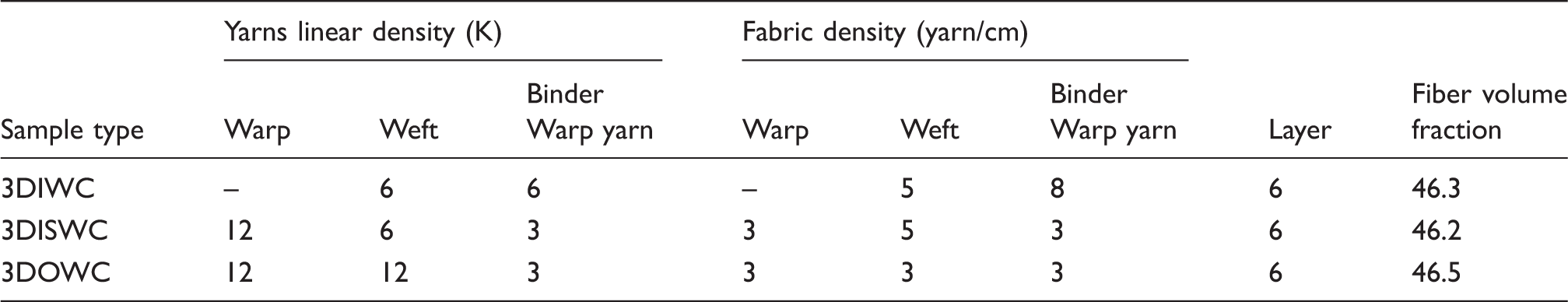
We chose three typical 3D woven fabrics (3D interlock woven fabric, 3D interlock woven fabric with stuffer warp, and 3D orthogonal woven fabric) as the reinforcement architectures in this study. The sketch diagrams of the three fabric structures are shown in Figure 1 to illustrate the specific preform structures.
The structures schematic of three-dimensional (3D) interlock woven fabric (a), 3D interlock woven fabric with stuffer warp (b), and 3D orthogonal woven fabric (c).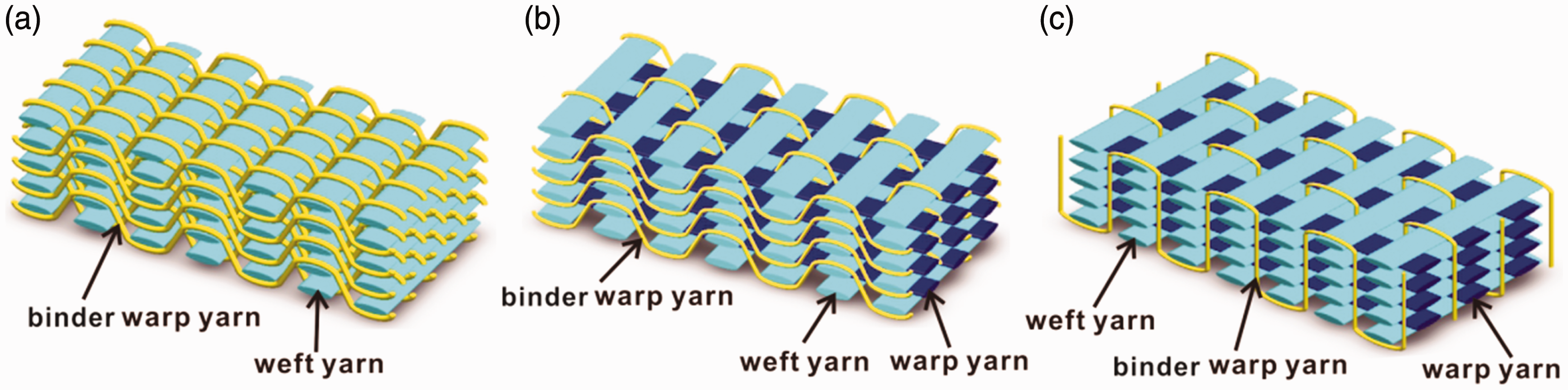
Structural parameters of the three-dimensional (3D) interlock woven fabric/epoxy composites (3DIWC), 3D interlock woven fabric with stuffer warp/epoxy composites (3DISWC), and 3D orthogonal woven fabric/epoxy composites (3DOWC)
Characterization methods
A free-space measurement system was used to evaluate the broadband EM characteristics of the 3D woven composites studied in this paper. The free-space measurement system was composed of two horn antennas (transmit and receive antennas) for a broadband frequency range of 8–18GHz, a sample holder, a data acquisition system, and a vector network analyzer (Agilent Technologies, ZNB40). The network analyzer consisted of a synthesized sweeper and a scattering parameter (S-parameter) test set. The S-parameter test set in the network analyzer was linked to the broadband horn antennas through precision coaxial cables and circular-to-rectangular waveguide adapters. A schematic of the experimental setup is shown in Figure 2. The two identical horn antennas were mounted 80 cm apart. The composite under test was mounted in the central plane of the two antennas on a low loss polystyrene block. The test sample was illuminated with a polarized EM wave at normal incidence and the reflection and transmission were investigated by measuring the reflection scattering parameter (S11) and transmission scattering parameter (S12) with the free-space measurement system. The EM wave perpendicularly struck the composite surface and the E field was parallel to the weft direction of the composites.
Schematic configuration of the free-space measurement system for characterization of the electromagnetic properties of materials.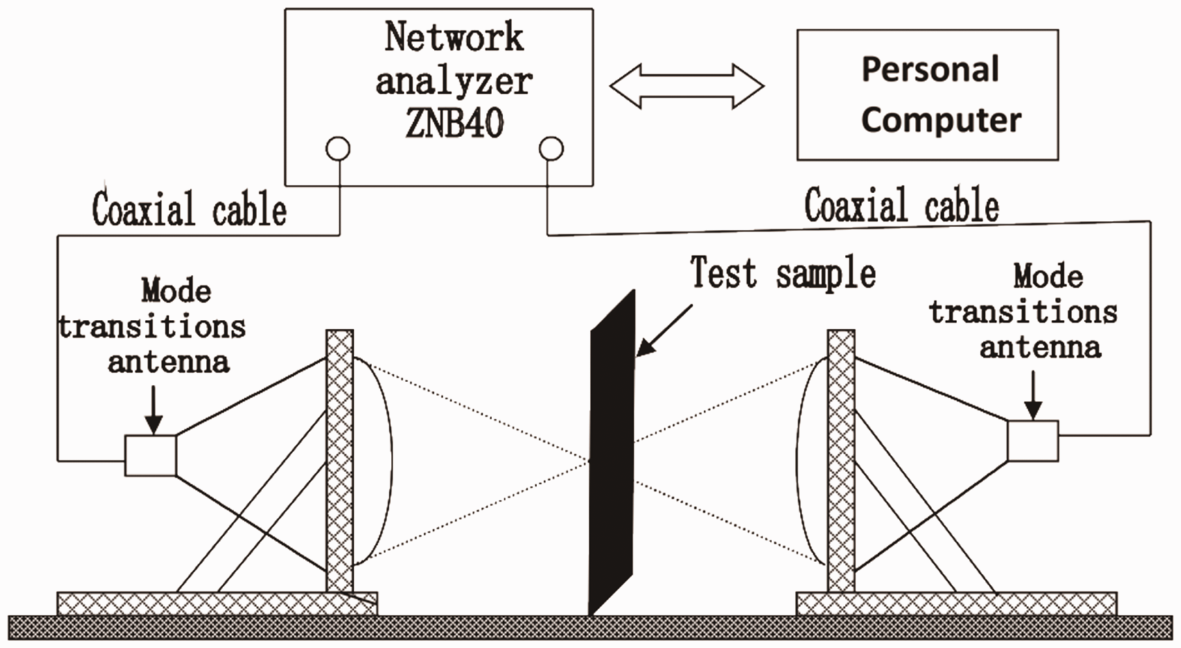
The measurement system was calibrated for reflection and transmission with an electronic calibration module (ZV-Z54 10 MHz–40 GHz). The vector network analyzer calibration process is shown in Figure 3. After calibration, the S-parameter of the composite samples can be tested according to the GJB 2038A-2011 standard (measurement methods for reflectivity of radar absorbing material). The test process was conducted at 20℃ and 60% relative humidity in the constant temperature and humidity laboratory of Tianjin Polytechnic University.
The vector network analyzer calibration process.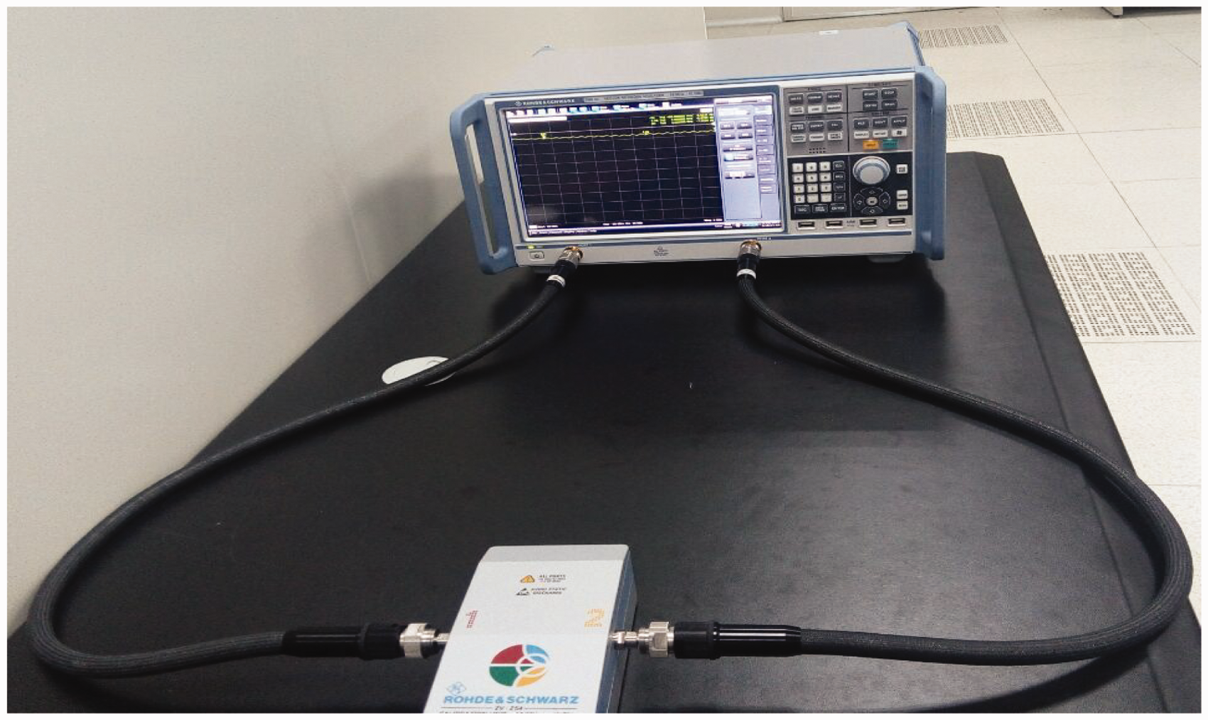
After the EM properties testing, the large pieces (380 mm × 180 mm × 4 mm) were sectioned into small sizes (20 mm × 20 mm × 4 mm) with a water-cooled diamond wheel saw. The cut surfaces were polished by using 360, 800, 2000 grit sandpaper and microcloth (silk fabric) in order for them to be uniform and smooth. Then the cross-section morphology of the composites was examined in a Zeiss Stemi 2000-C Stereo Microscope, which offers a wide variety of standard features and options that will meet the most rigorous application demands.
Basic theory of electromagnetic transmission
The RAM attenuates the incident EM wave by transmission or absorption, while the shielding material attenuates the incident EM wave by reflection or absorption. When an EM plane wave (EI) strikes a monolithic conductive material having different intrinsic impedance, two waves will be created at the external surface: a reflected wave (ER) and a transmitted wave (EI–R), as shown in Figure 4. The amplitude of the ER and EI–R waves depends on the intrinsic impedance of the RAM and the EM incident wave propagating domain. As the transmitted wave from the external surface (EI–R) travels in the conductive shield, the strength (amplitude) of the wave exponentially decreases due to absorption. The absorbed energy will be dissipated as heat.
26
Once the wave reaches the second surface of the sheet (x = h), a portion (ET) of the wave will be transmitted from the sample and a portion (EM) will be reflected into the sample (note that this first reflection from the internal surface is part of the reflection mechanism).
Schematic view of electromagnetic wave interaction with radar absorption material.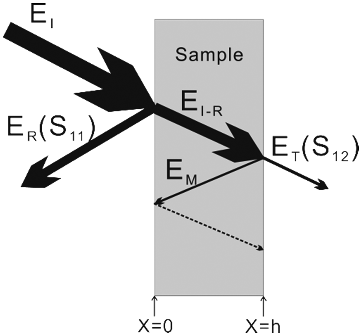
Results and discussion
Electromagnetic transmission characteristics of the composites
In order to investigate the contribution of absorption, reflection, and transmission to the overall incident EM power of the three composites, power data collected from the EM transmission characterization setup were analyzed. The EM characterization setup used directly measures the transmitted power (T) and reflected power (R). The currently available characterization tools are incapable of separately evaluating the multiple-reflection effect. So for practical purposes, the measured R is not only the power that has been reflected from the external surface, but also includes the positive contribution of internal surface reflection and negative contribution of multiple-reflection. The incident power (I) was a constant (I = 1 mW), so the absorbed power (A) can be calculated by the following equation

In a two-port network analysis system, the scattering parameters (S), that is, S11 (S22) and S12 (S21) can be correlated to the reflection and transmission coefficient. R and T of the RAM can be represented as
28
According to Equations (1)–(3), we can calculate the incident, reflected, transmitted, and absorbed power of the three composites. The power balance in the X-band (8–12 GHz) and Ku-band (12–18 GHz) frequency range for 3DIWC, 3DISWC, and 3DOWC as a function of frequency is shown in Figure 5. There were five samples for each of the 3DIWC, 3DISWC, and 3DOWC. The reported power values were the average values of the 3DIWC, 3DISWC, and 3DOWC.
Power balance in the X-band and Ku-band frequency range for three-dimensional (3D) interlock woven fabric/epoxy composites (a), 3D interlock woven fabric with stuffer warp/epoxy composites (b), and 3D orthogonal woven fabric/epoxy composites (c) as a function of frequency.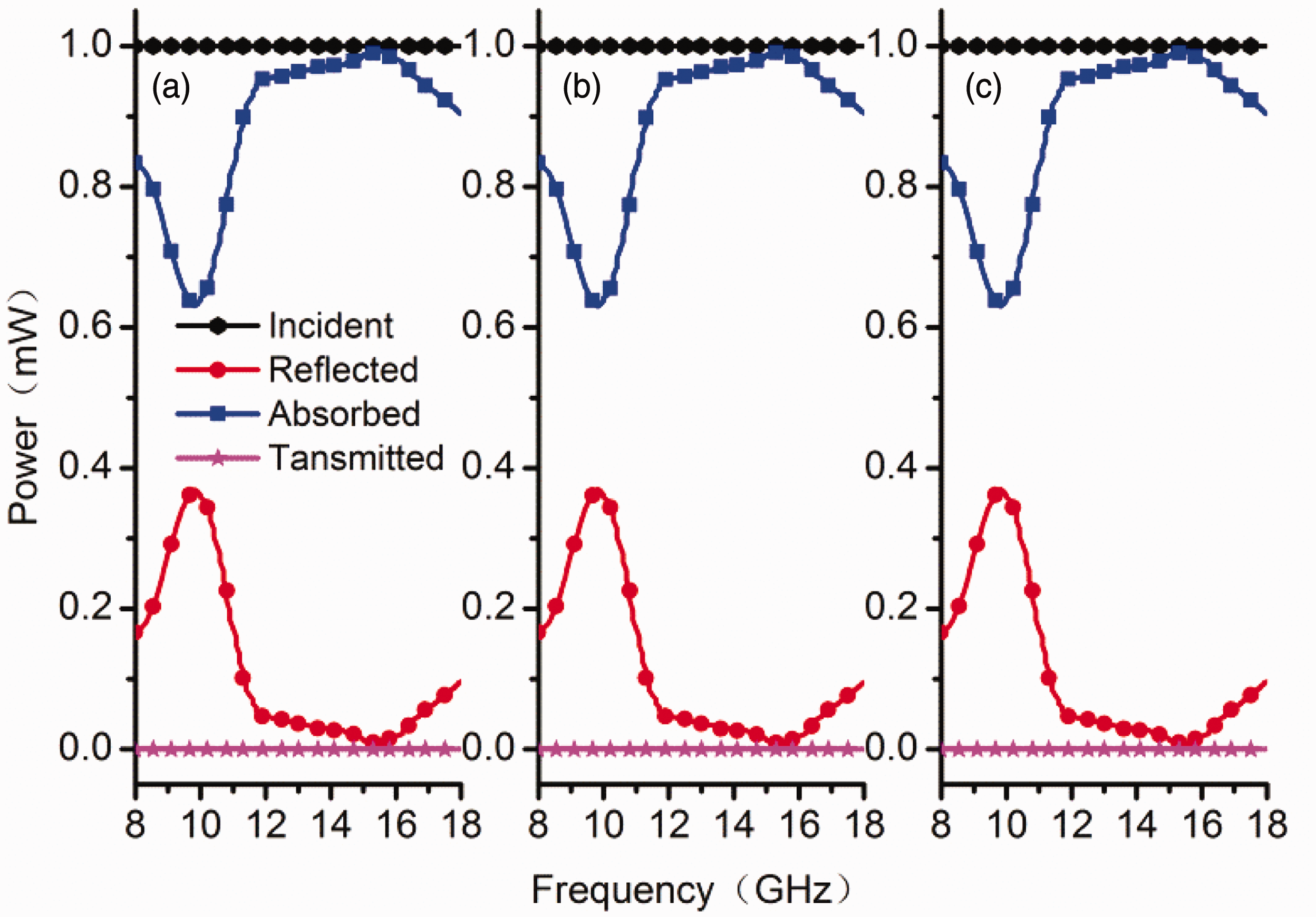
It is clearly seen that regardless of the reinforcement architecture, the amount of energy blocked by absorption was higher than that by reflection, especially when the frequency was more than 11.4 GHz, that is, the A values were larger than 0.9 mV, while the R values were smaller than 0.1 mV in the Ku-band frequency range. Besides, the maximum transmitted power of the 3DIWC, 3DISWC, and 3DOWC were all lower than 0.024%, which meant that all EM wave incidents on the composites were reflected and absorbed. This was because the carbon fabric was a good electrical conductor and the thicknesses were larger than skin depth. Therefore, we can reasonably conclude that the absorption is the dominant radar absorption mechanism of the 3DIWC, 3DISWC, and 3DOWC, and meanwhile the three kinds of composites can be used as EM shielding materials.
The absorption properties of the three kinds of composites
The EM absorption rate of the RAM can be evaluated in terms of the refection loss (RL), which is the logarithmic scales of the ratio ER and EI expressed by the following equation
5
Figure 6 shows the average reflection loss of the 3DIWC, 3DISWC, and 3DOWC in the frequency range of 8–18 GHz. It can be seen that the three kinds of composites had a similar reflection loss curve. The maximum reflection losses for the 3DIWC, 3DISWC, and 3DOWC were −23.7, −24.5, and −24.8 at the frequency of 15.4 GHz, respectively. The absorption bandwidth of −10 dB for each composite was 7.8 GHz (11.2–18 GHz). In other words, the three kinds of composites absorbed more than 90% of the incident microwave radiation over a broadband frequency range of 11.2–18 GHz. The absorption bandwidth of −20 dB (99% absorption) of reflection loss for the 3DIWC was 0.9 GHz (from 15.0 to 15.9 GHz), and for the 3DISWC and 3DOWC was 1.1 GHz (from 14.9 to 16.0 GHz). Furthermore, the three kinds of composites showed more than 60% absorptivity (below −4 dB) over a broadband frequency range of 8–11.2 GHz. Xin et al.
29
reported that the reflection loss of the T300 carbon fiber/epoxy unidirectional composites with 50% fiber volume fraction was from −1 to −2 dB in the frequency range of 8–18 GHz. By comparison, it is not difficult to discover that the 3D woven composites exhibited better EM absorption properties than the unidirectional composites over a broadband frequency range of 8–18 GHz.
The reflection loss of the three kinds of composite structures in the frequency range of 8–18 GHz. 3DIWC: three-dimensional (3D) interlock woven fabric/epoxy composites; 3DISWC: 3D interlock woven fabric with stuffer warp/epoxy composites; 3DOWC: 3D orthogonal woven fabric/epoxy composites.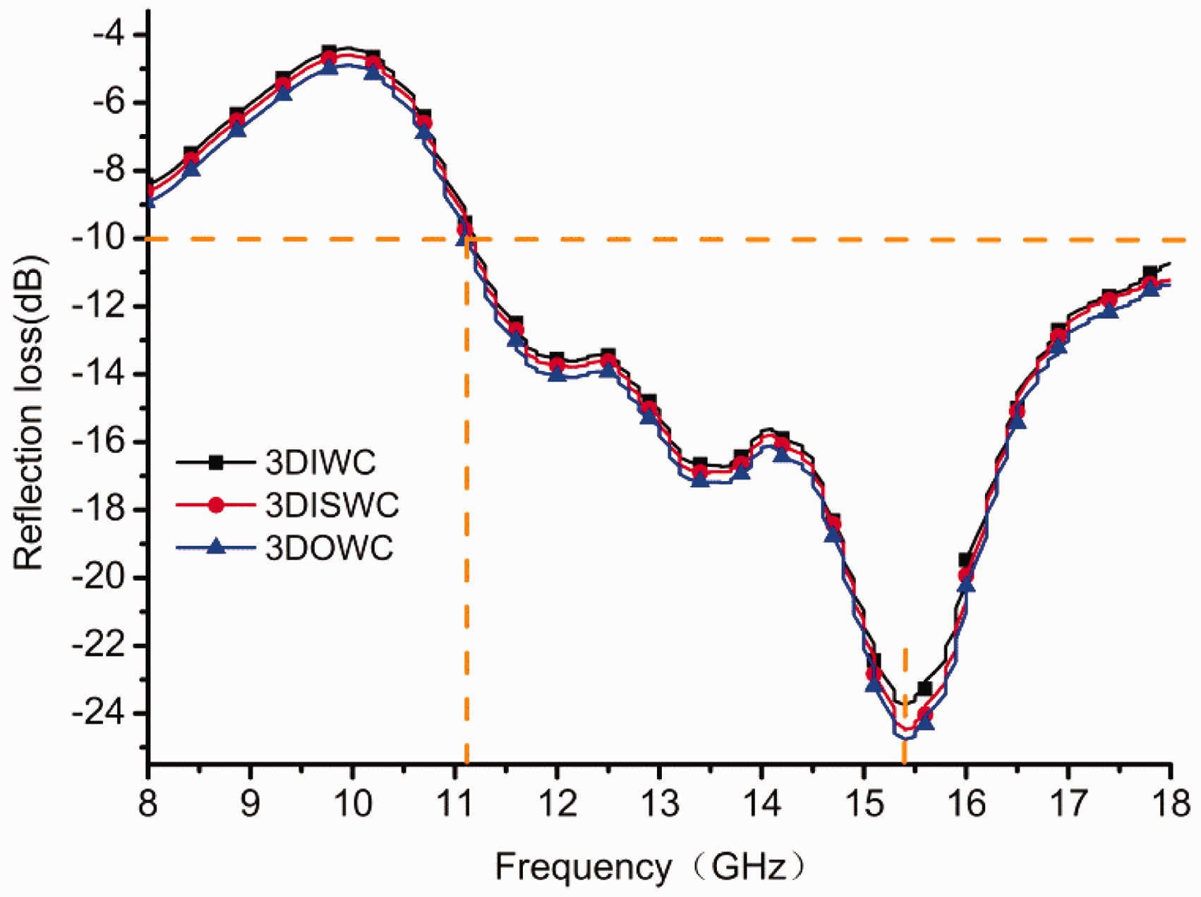
The cross-section photomicrographs of the three kinds of compositess were investigated by a Zeiss Stemi 2000-C Stereo Microscope, as shown in Figure 7. In the 3DIWC (Figure 7(a)), the binder yarns showed a different undulation connecting the weft yarns of the upper layer and under layer, and the weft yarns were extruded by the binder yarns to become crimp. The 3D interlock woven fabric with stuffer warp (Figure 1(b)) was made by adding the warp yarns into the 3D interlock woven fabric. The warp yarns and weft yarns were almost straight, and only the binder yarns showed a different extent of crimp (Figure 7(b)). In 3D orthogonal woven fabric (Figure 7(c)), the weft (y-directional) and warp (x-directional) yarns in the x–y plane without any crimp and the multiple layers of warp and weft yarns were interlaced by a set of binder yarns (z-yarns), which held the fabric through-thickness together. From Figure 7(c), it can be seen that the binder yarns remained straight in the thickness direction and only became crimp at the corner of the material face.
Cross-section photomicrographs and the corresponding schematic diagrams of three-dimensional (3D) interlock woven fabric/epoxy composites (a), 3D interlock woven fabric with stuffer warp/epoxy composites (b), and 3D orthogonal woven fabric/epoxy composites (b).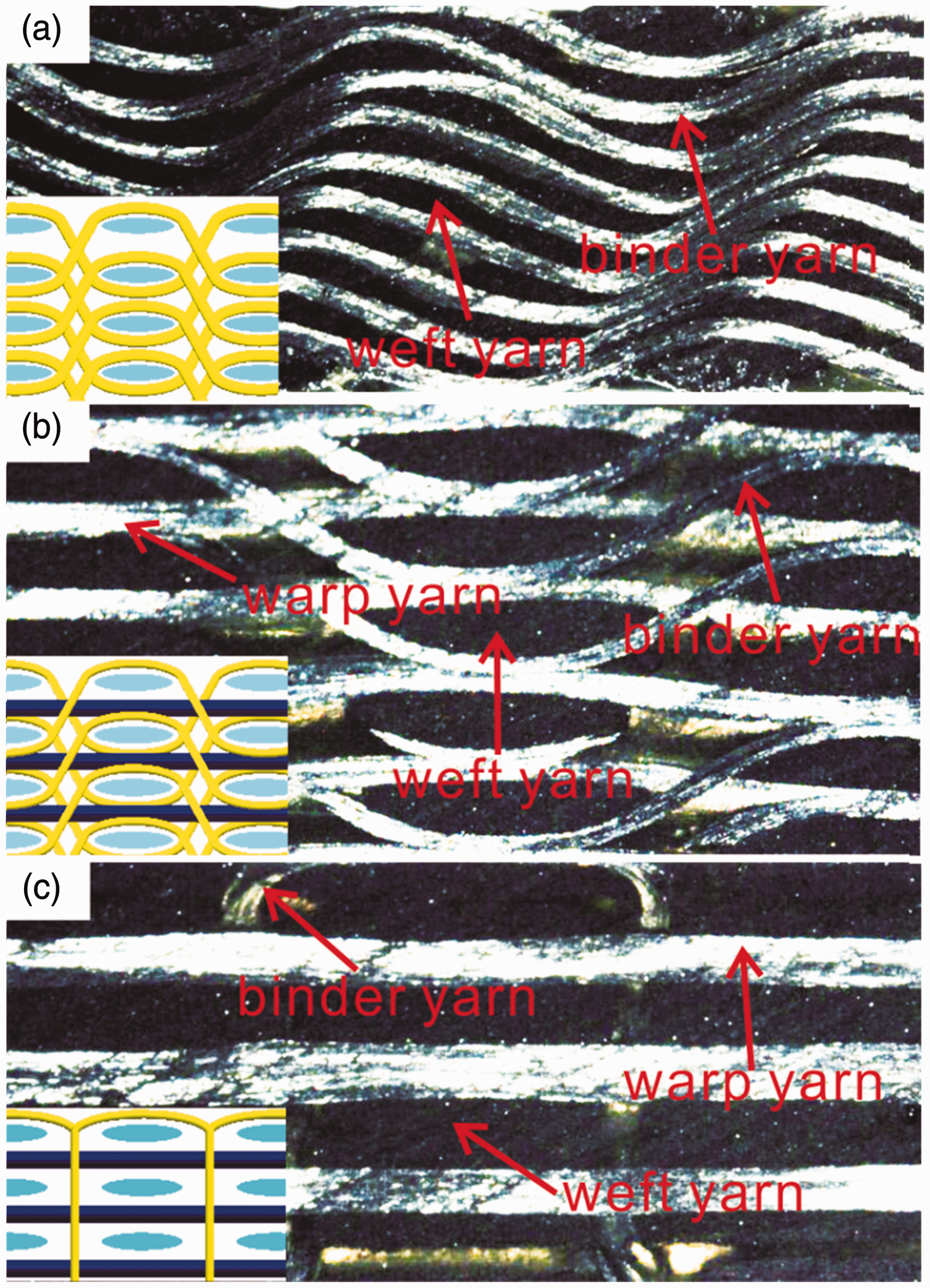
The study of Stonier RA 30 showed that many tiny pyramids formed at the interlaced areas of the yarns in the carbon fiber polymer composite, which like the microwave dark rooms were conducive to the EM absorbing. There were more interlaced places in the 3DISWC, 3DIWC, and 3DOWC, which formed many tiny pyramids that made the 3DISWC, 3DIWC, and 3DOWC have good absorption capacity.
The transmission properties of the three kinds of composites
Figure 8 shows the average transmitted power of the 3DIWC, 3DISWC, and 3DOWC in the frequency range of 8–18 GHz.
Transmitted power in the frequency range of 8–18 GHz for the three-dimensional interlock woven fabric/epoxy composites (3DIWC) (a), three-dimensional interlock woven fabric with stuffer warp/epoxy composites (3DISWC) (b), and three-dimensional orthogonal woven fabric/epoxy composites (3DOWC) (c) as a function of frequency.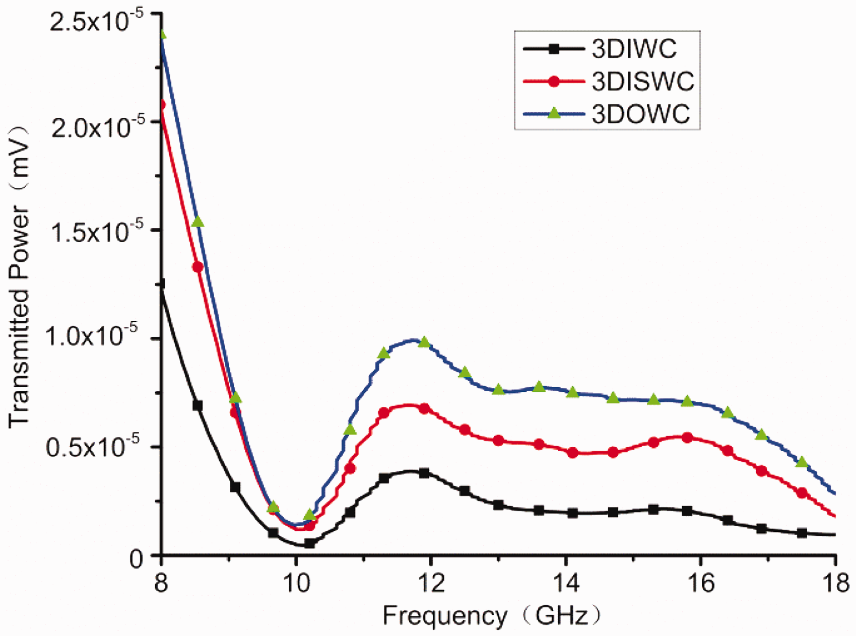
It is seen that the transmitted power of the 3DOWC was greater than that of the 3DISWC, which was greater than that of the 3DIWC. The resin-rich areas formed in the tiny pyramids, which were conducive to the EM propagation through the thickness of the composites. There could be more interlaced places in the 3DISWC than in the 3DIWC (Figure 7), so the transmitted power of the 3DISWC was larger than that of the 3DIWC. The numbers of interlaced point of the 3DOWC had no difference with those of the 3DISWC, but there were z-yarns in 3DOWC. The carbon fibers in the vertical-arranged manner in the 3D composites could be formed into resin ducts along the z-yarns, so the transmitted power of the 3DOWC was larger than that of the 3DISWC.
The EM interference shielding effectiveness (EMI SE) of shielding materials can be expressed as
26
The EMI SE of the 3DIWC, 3DISWC, and 3DOWC as a function of frequency is shown in Figure 9. From Figure 9, it is seen that the EMI SE of the 3DIWC was larger than that of the 3DOWC, which was larger than that of the 3DISWC. These results corresponded to the transmission properties shown in Figure 8. Besides, the total EMI SE of each composite is larger than 46 dB.
Total electromagnetic interference shielding effectiveness as a function of frequency. 3DIWC: three-dimensional (3D) interlock woven fabric/epoxy composites; 3DISWC: 3D interlock woven fabric with stuffer warp/epoxy composites; 3DOWC: 3D orthogonal woven fabric/epoxy composites.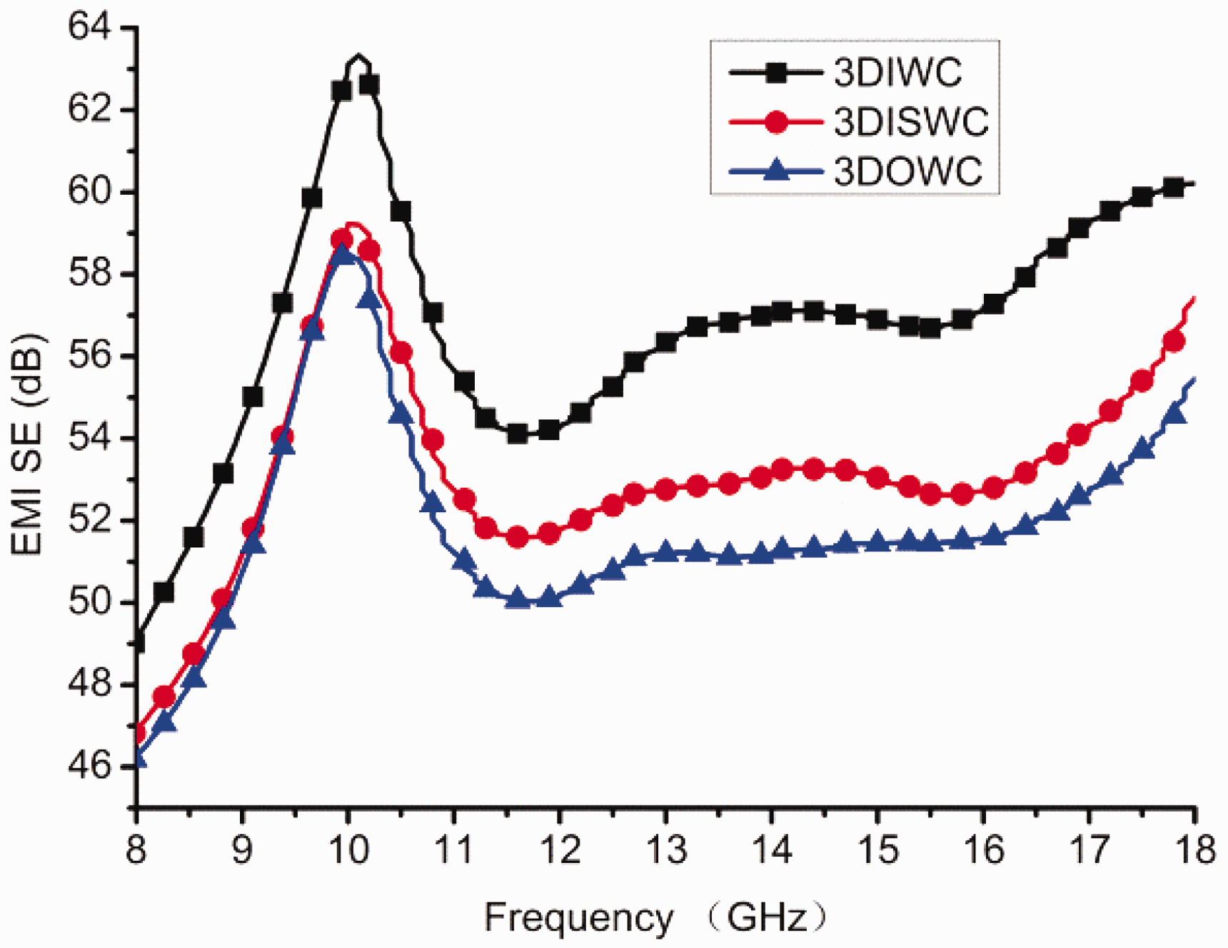
The value of EMI SE of a material indicates how much incident signal is blocked by the shielding medium. A total of 20 dB EMI SE means 99%, while 30 and 40 dB mean 99.9% and 99.99% of incident radiation is blocked, respectively. The total EMI SE of the three types of 3D carbon fiber woven composite are all larger than 46 dB over the 8–12 GHz bandwidth, which is evidence that the three types of 3D carbon fiber woven composites can be used as excellent shielding materials for EMI. As we know that for commercial application purposes the minimum EMI SE of a shielding material should be 20 dB, the three types of 3D carbon fiber woven composites can meet the commercial requirements.
Conclusions
In order to investigate the reinforcement architecture effect on the EM wave properties of carbon fiber reinforced polymer composites, the 3DIWC, the 3DISWC, and the 3DOWC were studied by the free-space measurement system. The results showed that regardless of the reinforcement architectures, the 3D woven carbon fiber fabric/epoxy composite absorbed more than 60% EM power and transmitted less than 0.024% over the 8–18 GHz bandwidth. It meant that the absorption was the dominant radar absorption mechanism of the 3DIWC, 3DISWC, and 3DOWC, and meanwhile the 3DIWC, 3DISWC, and 3DOWC can be used as EM shielding materials. The EM wave absorption properties of the three kinds of composites were more than 90% (below −10 dB) over the 11.2–18 GHz bandwidth, and more than 60% (below −4 dB) over the 8–12 GHz bandwidth. Therefore, the three kinds of composites described herein exhibited good EM wave absorption properties over a broadband frequency range of 8–18 GHz.
The numbers of tiny pyramids formed at the places of interlaced yarns and the fiber arrangement in the thickness direction of the composites influence the extent of the transmitted properties. The resin-rich areas formed in the tiny pyramids were conducive to the EM propagation through the thickness of the composites, and the 3DISWC had more tiny pyramids than the 3DIWC, so the transmitted power of the 3DISWC was greater than that of the 3DIWC. The number of interlaced points of the 3DOWC had no difference with those of the 3DISWC, but there were z-yarns in 3DOWC. The carbon fibers in the vertical-arranged manner in the 3D composites could be formed into resin ducts along the z-yarns, so the transmitted power of the 3DOWC was larger than that of the 3DISWC.
The 3DIWC, 3DISWC, and 3DOWC not only had good EM wave absorbability but also excellent mechanical properties; hence, they can be used as a RAS in a weapon system, such as for fighters, warships, and missiles. Besides, 99.99% of incident radiation is blocked by the 3D carbon fiber woven composite over the 8–12 GHz bandwidth, which is evidence that the three types of 3D carbon fiber woven composites can be used as excellent shielding materials for EM interference. These 3D woven structures provide an easy and effective way to design and improve the EM wave absorbability of carbon fiber reinforced polymer composites. However, we need to further adjust the structure parameter of reinforcement to make the 3D woven structures absorb 90% EM energy over the entire frequency range of radar. Only then can they be the material of choice for military applications.
Footnotes
Declaration of conflicting interests
The authors declared no potential conflicts of interest with respect to the research, authorship, and/or publication of this article.
Funding
The authors disclosed receipt of the following financial support for the research, authorship, and/or publication of this article: This work was supported by the National Natural Science Foundation of China (Grant No:51603163), the Science and Technology Project of Shaanxi, China (Grant No:2017JQ5056), the Science and Technology Project of the China Textile Industry Association (Grant No:2016050), the Science and Technology Project of Shaanxi Education Department, China (Grant No:16JK1343), the Young Talent Foundation of the University Association for Science and Technology in Shaanxi, China (Grant No:20160123), the Sanqin Scholar Foundation of Shaanxi Province, China, the Doctoral Program of Xi'an Polytechnic University, China (Grant No:BS1514), and the Cooperative Innovational Center for Technical Textiles, Shaanxi Province, China (Grant No:2015ZX-02).