
Abstract
Grafting graphene on polyethylene terephthalate (PET) fibers requires a large number of environmentally harmful chemicals. In this study, a facile high-temperature and high-pressure method of inlaying graphene nanoplatelets was applied to fabricate anti-ultraviolet (UV) and anti-static graphene/PET composites. The resulting graphene-inlaid (GI) PET fabric, which showed excellent anti-ultraviolet and anti-static properties, was characterized by scanning electron microscopy, energy-dispersive X-ray spectroscopy, Fourier transform–infrared spectroscopy and X-ray diffraction. Results suggested that graphene had been inlaid into the PET fiber surface, and that the optimal inlaying conditions were as follows: inlaying temperature 200℃, inlaying pressure 15 MPa, and inlaying time 15 s. The UV protection factor of the GI PET fabric under optimal conditions could reach 50+ and was maintained at 50+ after 50 laundering cycles. The peak values of the static voltage and its half-time in the GI PET fabric could be reduced from 500.0 V to 10.0 V and from 7.39 s to 0.53 s, respectively, and the electrical resistivity of the GI PET fabric was 36.04 ± 0.14 kΩ.cm. The breaking strengths of the GI PET fabrics could be retained over 70.0% that of the pure PET fabric. The facile high-temperature and high-pressure inlaying method is an eco-friendly technique that requires very few chemicals, except for ethyl alcohol.
Polyethylene terephthalate (PET) is one of the most widely used synthetic fibers, and is indispensable in the textile industry because of its excellent wrinkle resistance, high tensile strength and other superior mechanical properties.1,2 However, PET fabric has certain disadvantages, including weak ultraviolet (UV) resistance 3 and ease of generating static electricity. 4 UV radiation is generated by the excitation of the outer electrons of the atom and can induce dose-related acute and chronic changes in the skin, including erythema, photoaging and even cancer. Static electricity is a charge that is in a static state or is not flowing, which causes us to have an uncomfortable feeling. Thus, the fixing of nanomaterials into the surface of PET fabrics has been extensively examined to enhance their UV resistance and anti-static properties. These nanomaterials include nanometer zinc oxide, 5 nanotitanium dioxide, 6 nanostructured LaB6, 7 carbon nanotubes 8 and graphene. 9 Specifically, graphene immobilized on PET fabrics has been widely evaluated to render textiles multifunctional 10 because graphene exhibits excellent electronic, 11 UV-resistant, 12 thermal, 13 antibiotic, 14 anti-radiation 15 and mechanical 16 properties arising from its particular two-dimensional structure. 17
Graphene is known to contain almost no active groups, is easy to aggregate and has a stable two-dimensional honeycomb lattice with a flat monolayer of carbon atom structures. 18 Thus, directly grafting graphene on to PET fabrics is difficult. 19 In general, graphene is first oxidized to graphene oxide (GO) by oxidizing agents for it to be dispersed in water solution; the GO can be subsequently absorbed onto the textile by inkjet printing, 20 spin-coating 21 and immersion of the textile into the GO turbid liquid; 22 GO on the textile is then reduced using reducing agents. 23 The interaction between graphene and fibers is maintained only by Van der Waals forces; thus, the finished textile is not durable. Several studies24–27 have indicated that GO can be grafted with reactive groups, and that the GO with reactive groups can be grafted on cellulose fabrics. Textiles prepared using this technique exhibit durability. However, these methods have certain disadvantages, including toxic chemical contents, a long reaction time, dangerous oxidation and high energy costs. Therefore, a green, simple and practicable novel technique to obtain a graphene-coated PET fabric with multifunctional properties needs to be developed.
In the current study, a facile high-temperature and high-pressure inlaying method was developed to inlay graphene nanoplatelets into the PET fiber surface to obtain multifunctional PET fabrics. The PET fabrics were processed in a plate vulcanizing press. This green treatment method requires no chemicals other than ethyl alcohol. The finishing process can be completed within a short period. Moreover, compared with the general redox method, this technique uses considerably less energy.
Experimental
Reagents and materials
PET fabrics (plain weave, 34 g/m2, 650/10 × 550/10 cm, thickness 0.07 mm) were purchased from Chongqing Chaotianmen Market (China); graphene nanoplatelets (thickness 4–20 nm, microchip size 5–10 µm, no more than 20 layers) were supplied by Aladdin Industrial Corporation in Shanghai (China); sodium dodecyl benzene sulfonate (SDBS), anhydrous sodium carbonate, and anhydrous ethanol, which were of analytical reagent-grade, were acquired from Chongqing Chuandong Chemical Co., Ltd (Chongqing, China); and detergent without optical brightener (WOB) was supplied by MIEN instrument Co., Ltd (Shanghai, China). All chemicals were used without further purification.
Fabrication of graphene-inlaid PET fabric
PET fabrics were cut into 10 × 10 cm fragments, washed with solutions of 0.1% SDBS and 0.1% sodium carbonate (w/w) at 100℃ for 30 min, cleaned with distilled water and then dried in a dryer at 60℃. Up to 3 g of graphene nanoplatelets were dispersed homogeneously in a 200 mL anhydrous ethanol solution in a 500 mL beaker. Dispersion was conducted by bath sonication at 50℃ for 60 min in an ultrasonic cleaner. PET fabric samples were immersed into the graphene turbid liquid, ultrasonically treated at 50℃ for 60 min, aired at room temperature and cured under varying temperature (180, 190, 200, 210 or 220℃) and pressure (11, 13, 15, 17 or 19 MPa) conditions on a plate vulcanizing press for a certain period. Immersion and inlaying of each PET fabric were repeated once under similar conditions to increase the graphene inlaying rate. After the graphene was inlaid, the treated PET fabric samples were baked on a continuous-setting dryer at 100℃ for 5 min. The PET fabric samples were washed with a 0.15% SDBS solution in a constant-temperature shaker at 49℃ for 45 min and cleaned with a large amount of distilled water. The graphene-coated samples were finally dried at 60℃, following which the graphene-inlaid (GI) PET fabric was obtained.
Characterization
Images of the original and treated PET fabrics were obtained by scanning electron microscopy (SEM) using a Phenom Pro scanning electron microscope (Phenom World, The Netherlands). The original and treated PET fabrics were coated with gold using a sputter coater to clearly capture their surface morphologies. Elemental analysis of the surfaces of the pure and GI PET fabrics was conducted using a JSM-6610 scanning electron microscope with an energy dispersive X-ray (EDX) detector, and the results were the average of six tests on different sections. Fourier transform-infrared spectroscopy (FT-IR) of the PET fibers before and after inlaying graphene was performed with a Spectrum GX (Perkin-Elmer Co., USA) using KBr pellets. The spectra of all PET fibers were acquired in the 400–4000 cm−1 range with 2 cm−1 resolution. X-ray diffraction (XRD) was performed using an XD-3 diffractometer with CuK alpha radiation (36 kV, 20 mA) (Beijing Purkinje General Instrument Co., Ltd, Beijing, China). Diffraction patterns were obtained from 5 to 70o with a step size of 0.02o (λ = 0.15 nm). Thermogravimetric (TG) analysis of the original and treated PET fabrics was conducted using a Pyris 1 thermogravimetric analyzer (PerkinElmer, USA) from 40 to 800℃ at 10℃/min under N2 flow of 20 mL/min.
Inlaying graphene rate and mechanical analyses of treated PET fabric samples
The weights of the 5 × 5 cm PET fabric samples were evaluated using an FA2004A JingTian electronic analytical balance (Electronic Instrument Co., Ltd, Shanghai, China). The inlaying graphene rate (IGR) of the PET fabric was calculated using equation (1)
The breaking strength of the 5 × 2 cm PET fabric were evaluated using a YM065 electronic fabric strength machine (Yuan More Instruments Factory Co., Ltd, China). The tensile strength retention rate (TSRR) of the GI PET fabric samples was calculated using equation (2)
UV measurement
A YG912E UV tester (Mebon Instruments Co., Ltd, Quanzhou, China) was used to measure the UV resistance of the PET fabric samples. The ultraviolet protection factor (UPF), ultraviolet A (UVA) transmittance and ultraviolet B (UVB) transmittance of the PET samples were obtained from the UV tester (UV 100 F) to characterize the UV resistance of the PET fabric samples, and the results were the average of six tests. In accordance with Australia/New Zealand AC/NZS standard 4399:1996, the UPF of the PET fabric samples was calculated using equation (3).
Anti-static measurement
The anti-static property of the samples was evaluated using a YG401 fabric induction-type electrostatic tester (Ningbo Textile Instrument Factory, China) under 10,000 V in accordance with the FZ/T01042-1996 standard. The discharge time of the instrument was 30 s. The static voltage and the half-life period of each PET sample was recorded. Three 8 × 6 cm samples were required to finish each test, and the results were the average of six tests.
Electrical resistance measurement
The electrical resistivity of the treated PET fabrics was measured by a Four-point Probes Resistivity Measurement System from Four Point Probe Technology (Guangzhou, China). Each sample was tested six times, and the average values were used.
Washing durability measurement
Each 10 × 5 cm GI PET fabric sample was washed in a 500 mL can containing a 200 mL 0.37% WOB detergent solution and 10 steel balls with a diameter of 6 mm at 40℃ for 45 min, in accordance with the American Association of Textile Chemists and Colorists (AATCC) testing method 61-2013. The TSRR, UPF, UVA transmittance, UVB transmittance, static voltage and its half-time, and the electrical resistivity of the treated PET fabric samples were measured after washing for varying times to clarify the durability of the fabric.
Results and discussion
Inlaying mechanism for GI PET fabrics
According to the schematic diagram shown in Figure 1, the thermal motion of the PET macromolecule chains and the high pressure used facilitate the diffusion of the graphene platelets into the fibers.28–30 At room temperature, the graphene nanoplatelets are fixed firmly into the fiber surface.
A schematic diagram of how graphene nanoplatelets are inlayed into the surface of a PET fiber.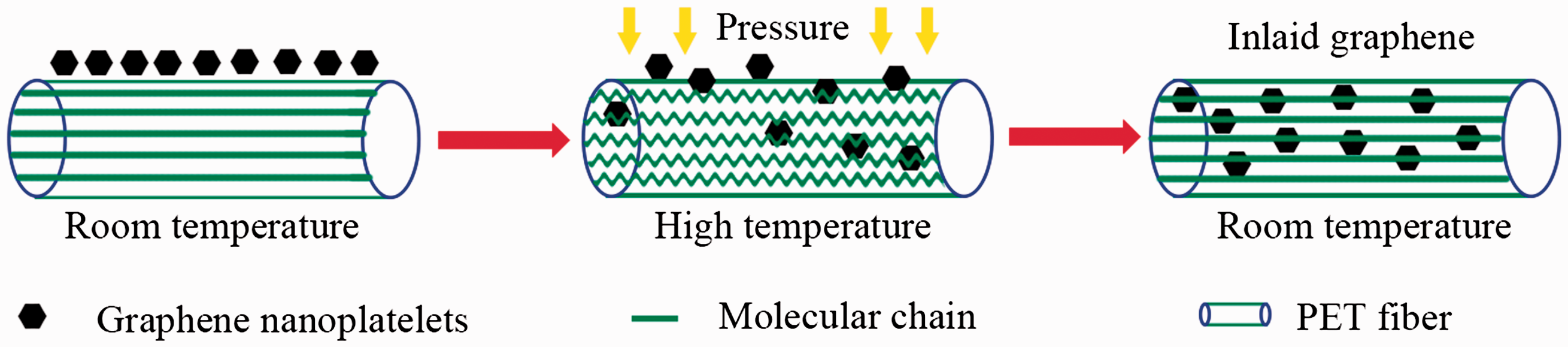
Structural characterizations
The SEM images of the pure PET fibers are shown in Figure 2(a) and (b). The pure PET fibers were round, smooth and clean. Some interspaces were present among fibers. Figure 2(c) and (d) present the GI fibers after high-temperature and high-pressure processing. The GI fibers were flat due to the large compressibility of the polymeric fibers and void spaces among individual fibers were largely reduced. The fiber surfaces were covered with some substances. Figure 2(e) and (f) show the SEM images of the GI fibers cured at 100℃ for 5 min; the flat fibers could be restored to their round shape by high-temperature treatment, verifying that the modifications induced by pressure on these fibers were reversible. From the cross-section SEM images of treated PET fabrics in Figure 2(i) and (j), the finished PET fibers were covered with a layer of graphene nanoplatelets. Moreover, the color of treated PET fabric changed from white (pure PET fabric) to gray, as depicted in Figure 2(g) and (h). These results indicated that graphene nanoplatelets were inlaid into the PET surface by using a high-temperature and high-pressure eco-technology.
Scanning electron microscopy images of the polyethylene terephthalate fiber surfaces. (a) and (b) pure polyethylene terephthalate fibers, (c) and (d) graphene-inlaid polyethylene terephthalate fibers under high-temperature and high-pressure conditions, (e) and (f) graphene-inlaid fibers cured at a high temperature and (i) and (j) cross-sections of graphene-inlaid fibers after the curing treatment. Photographs of pure (g) and treated (h) polyethylene terephthalate fabrics.
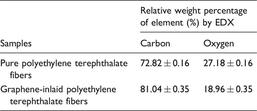
The main elemental composition of the pure PET fibers and GI PET fibers was obtained by EDX, namely carbon and oxygen, and the results are shown in Figure 3 and Table 1. The relative weight percentages of carbon and oxygen in the pure PET fibers were 72.82 ± 0.16% and 27.18 ± 0.16%, respectively. After the inlaying process, the relative weight percentages of carbon oxygen were 81.04 ± 0.35% and 18.96 ± 0.35%, respectively. The weight percentage increase in carbon indicated that graphene nanoplatelets were inlaid into the PET fabric.
EDX images of pure polyethylene terephthalate fibers (a) and graphene-inlaid polyethylene terephthalate fibers (b). Relative weight percentage of elements obtained by EDX for polyethylene terephthalate samples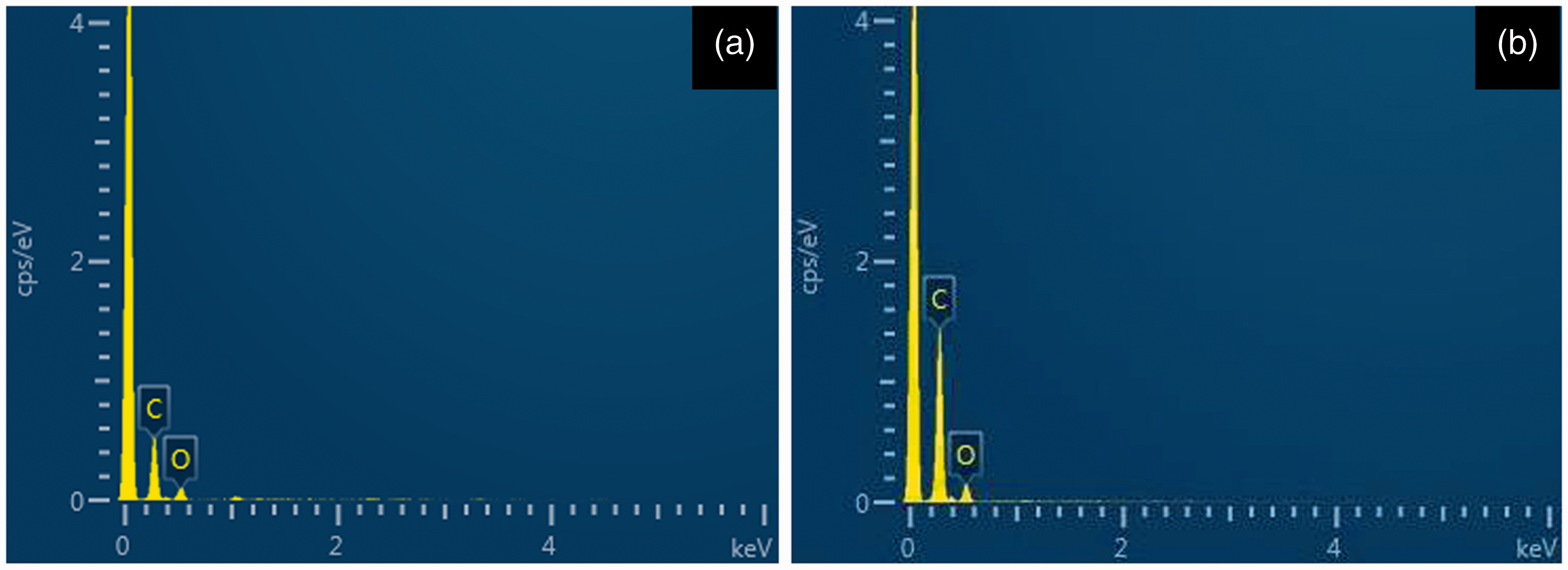
FT-IR was employed to analyze the structures of the pure PET fibers, treated PET fibers and graphene nanoplatelets. As shown in Figure 4, the peaks at 1709, 1503, 1241 and 723 cm−1 are attributed to C=O stretching, benzene ring skeletal, C-O stretching and C-H bending vibration for pure PET fibers, respectively.
31
A new absorption peak at 1631 cm−1 for the treated PET fibers corresponded to a C=C stretching vibration peak of graphene nanoplatelets.32,33 This result suggested that graphene nanoplatelets were inlaid into the PET fiber surface.
Fourier transform-infrared spectra of pure polyethylene terephthalate fibers, treated polyethylene terephthalate fibers and graphene nanoplatelets.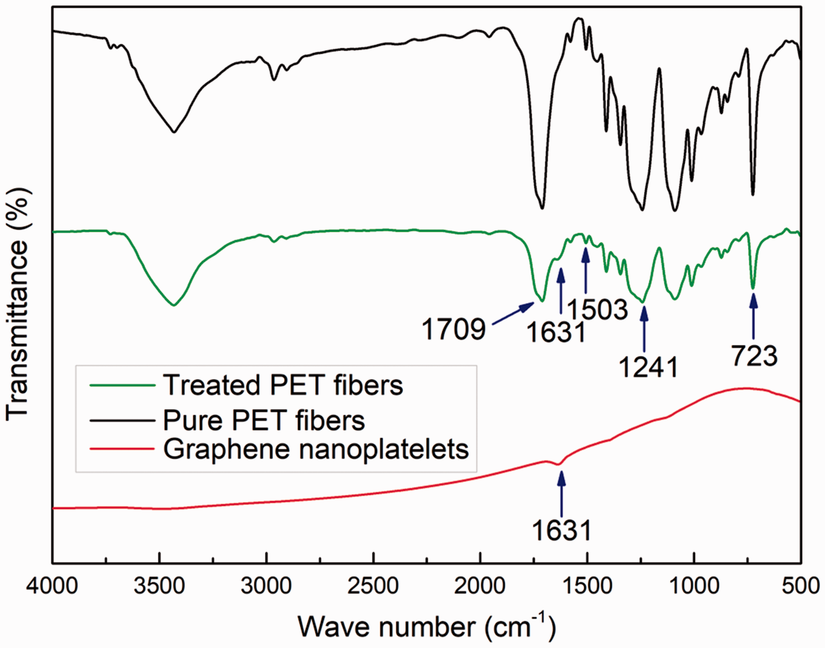
Figure 5 presents the XRD patterns of graphene nanoplatelets, original PET fibers and GI PET fibers. Two typical peaks at 26.48° and 54.71° agree with the graphite-like structure of graphene nanoplatelets, which is consistent with the results from other researchers.
33
The original PET fibers and GI PET fibers shared similar diffraction peaks at 17.52°, 22.64° and 25.58°, which are the characteristic XRD peaks of PET fiber,.
2
In addition, from the GI PET fiber XRD pattern, a new weak peak was observed at 26.29° corresponding to graphene nanoplatelets, which illustrates that graphene nanoplatelets were inlaid into the PET fibers.
X-ray diffraction pattern of graphene nanoplatelets, original polyethylene terephthalate fibers and graphene-inlaid polyethylene terephthalate fibers.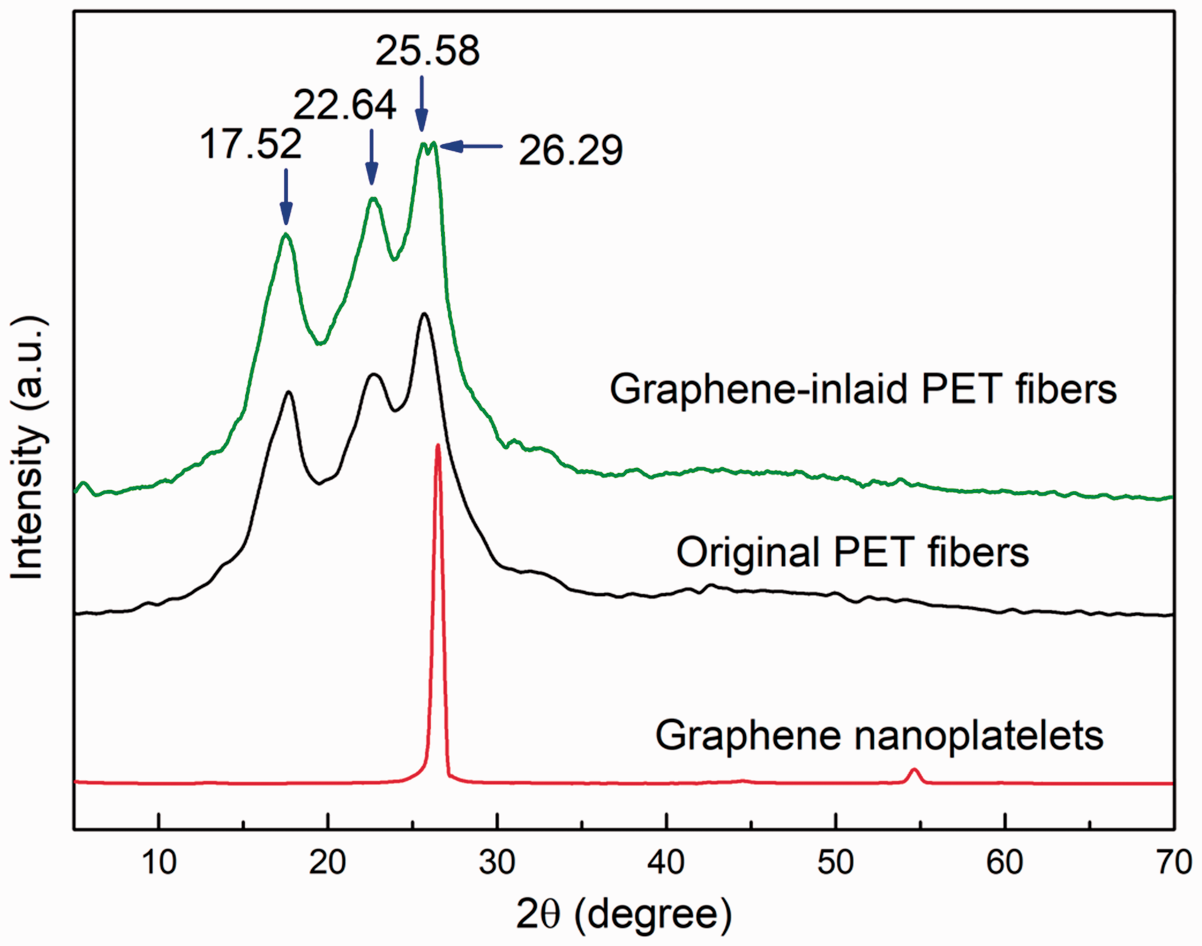
The thermal performance of the PET fibers before and after the inlaying of graphene nanoplatelets is shown in Figure 6. The variation tendencies of the TG curves of the original PET fibers and the treated PET fibers are similar. The weight loss of the original PET fibers was slightly higher than that of the GI PET fibers below 350℃. This difference could be attributed to the low absorption of water vapor by the GI PET fibers, compared with that of the PET fibers. The weights of the pure fibers and GI PET fibers decreased markedly from 350 to 500℃. This reduction was attributed to the decomposition of the PET fibers within this temperature range. The weight loss of the pure PET fibers was higher than that of the GI PET fibers as graphene is difficult to decompose at high temperatures. The weights of the fibers before and after inlaying graphene decreased slightly at temperatures higher than 500℃. The residuals of the original fibers and GI fibers at 700℃ were 0.54 and 4.42%, respectively, as the graphene nanoplatelets inlaid into the PET fibers surface were relatively steady.
TG curves of original polyethylene terephthalate fibers and treated polyethylene terephthalate fibers.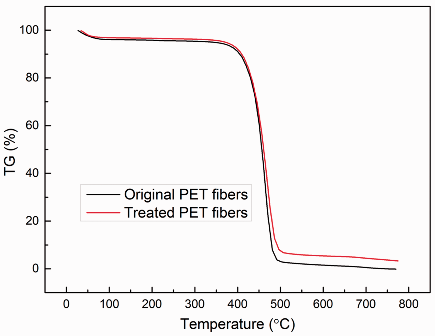
IGR of treated PET fabric
Figure 7(a) to (c) shows the influence of inlaying time, inlaying temperature and inlaying pressure on the IGR of the PET fabrics. The IGR increased with increasing inlaying time, temperature and pressure. Moreover, the IGR increased markedly under the following conditions: inlaying time 15 s; inlaying temperature 200℃ and inlaying pressure 15 MPa. However, the IGR increased only slightly with continuously increasing inlaying time, temperature and pressure. Owing to the limited inlaying space of the fiber surface, the IGR only increased a little when the inlaying temperature, pressure and time increased continuously.
Influence of inlaying time (a), temperature (b) and pressure (c) on the inlaying graphene rate.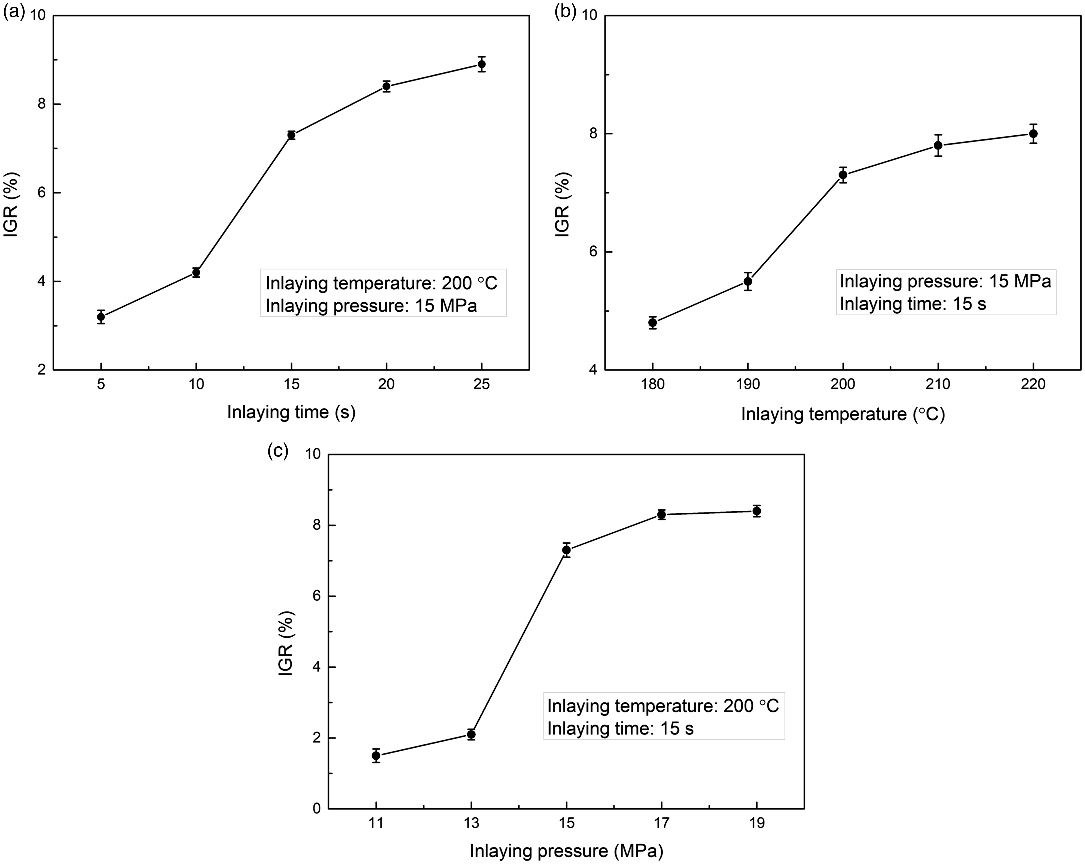
TSRR of the treated PET fabric
Figure 8(a) to (c) presents the changes in TSRR with inlaying time, temperature and pressure. At an inlaying temperature of 200℃ and inlaying pressure of 15 MPa, the warp and weft TSRRs of the PET fabric samples exceeded 70.0% for 15 s, as shown in Figure 8(a), and sharply decreased for over 15 s. When the inlaying time was 15 s and the inlaying pressure was 15 MPa, the warp and weft TSRRs of the PET fabric samples was maintained beyond 70.0% at 200℃, as shown in Figure 8(b). From Figure 8(c), it can be seen that the warp and weft TSRRs of the PET fabric samples remained higher than 70.0% only when the inlaying pressure was equal to or lower than 15 MPa. If the tensile strength of the GI PET fabrics had to be higher than 70.0%, the optimal inlaying conditions were as follows: inlaying temperature 200℃, inlaying pressure 15 MPa and inlaying time 15 s. Under the optimal inlaying conditions, the warp and weft TSRRs were 72.3 ± 1.1 and 75.4 ± 0.9 %, respectively, which exerted no influence on the wearability of the PET fabrics.
Changes in tensile strength retention rate with inlaying time (a), temperature (b) and pressure (c).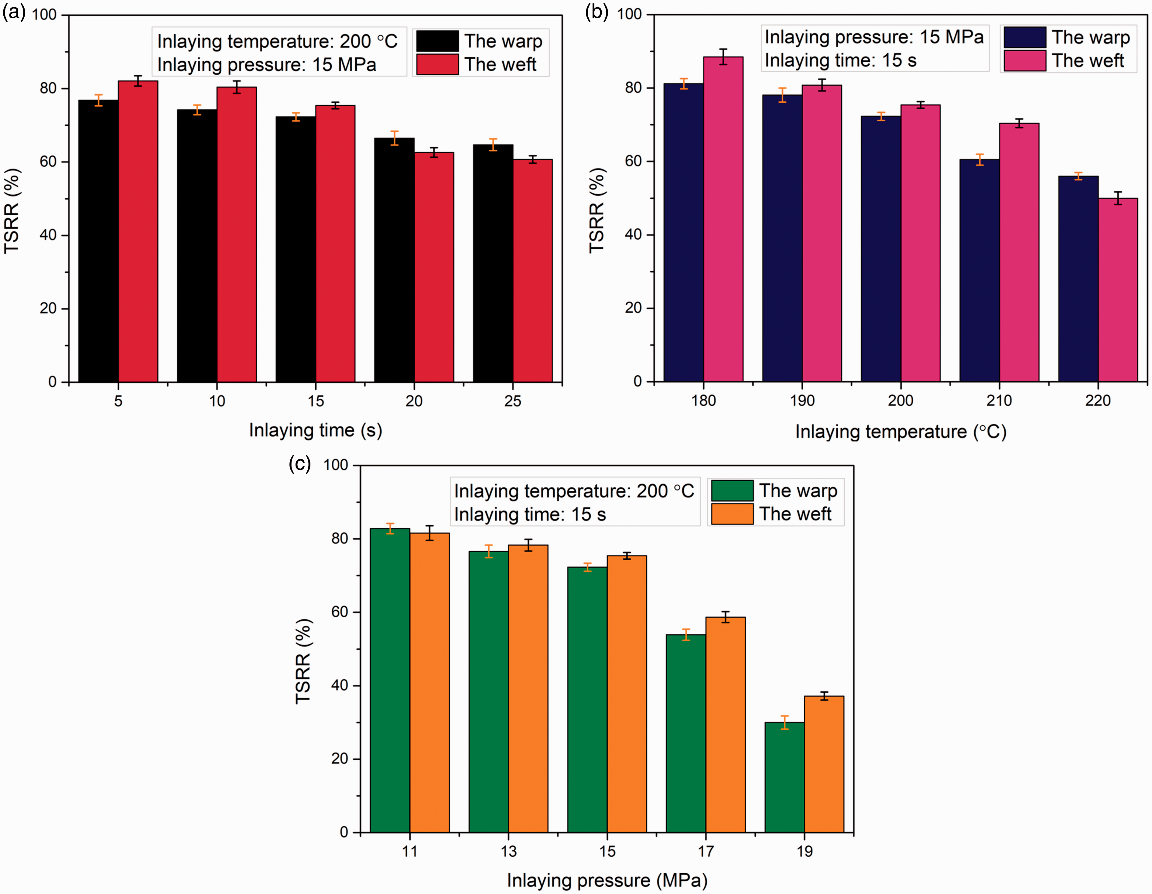
UV protection of PET fabrics before and after finishing
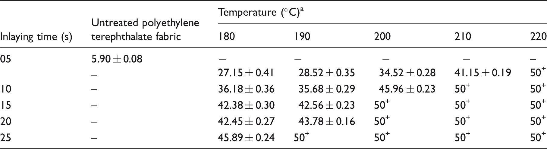
The ultraviolet A (UVA) transmittance, ultraviolet B (UVB) transmittance, and ultraviolet protection factor (UPF) of the PET fabric before and after the inlaying of graphene nanoplatelets are presented in Fig. 9 and Table 2. The UVA transmittance, UVB transmittance, and UPF of the pure PET fabric are 15.86 ± 0.11%, 16.78 ± 0.23% and 5.90 ± 0.08, respectively. The UVA and UVB transmittance rates of the GI PET fabric decreased markedly, as shown in Fig. 9. The lower the UVA and UVB transmittance, the higher the UV protection of the PET fabrics. In addition, the UPF of the GI PET fabric increased with increasing inlaying time and temperature, as shown in Table 2. Therefore, the UV protection of the treated PET fabrics was improved by the inlaid graphene nanoplatelets. When the PET fabric was inlaid with graphene nanoplatelets at 200℃ and 15 MPa for 15 s, its UPF reached 50+ , indicating excellent anti-UV protection. The warp and weft TSRR were 72.3 ± 1.1% and 75.4 ± 0.9%, respectively, under this condition, as shown in Fig. 8. Thus, the optimal inlaying conditions were as follows: inlaying temperature, 200℃; inlaying pressure, 15 MPa; and inlaying time, 15 s.
(a) Ultraviolet A transmittance and (b) Ultraviolet B transmittance of polyethylene terephthalate fabrics. Ultraviolet protection factor of treated polyethylene terephthalate fabrics at varying times and temperatures 15 MPa.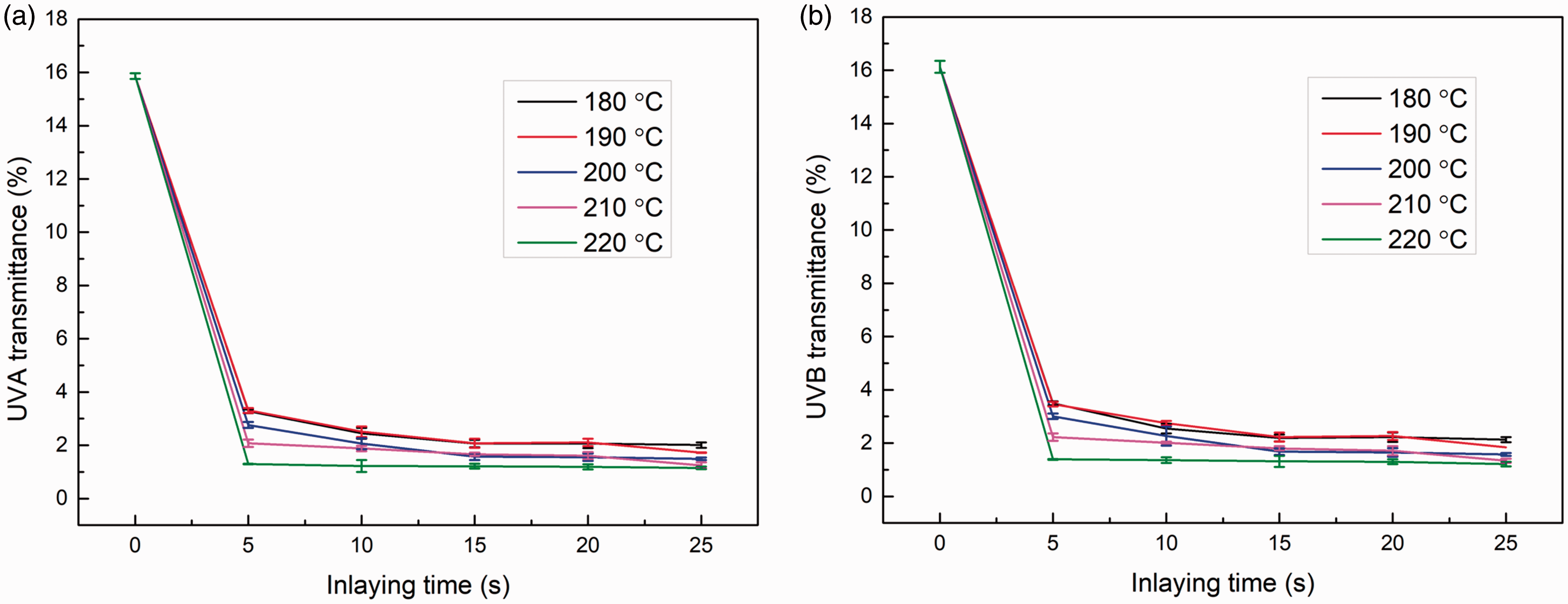
Anti-static properties of PET fabrics before and after finishing
Influence of inlaying time and temperature on the anti-static properties of the treated polyethylene terephthalate fabrics
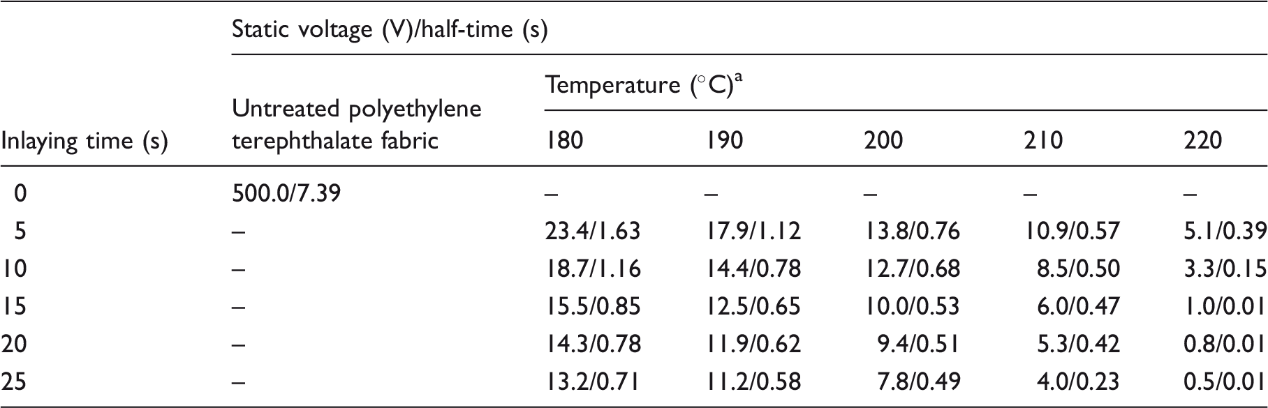
15 MPa.
Electrical resistivity of PET fabrics before and after finishing
Electrical resistivity of samples following different treatment times and temperatures
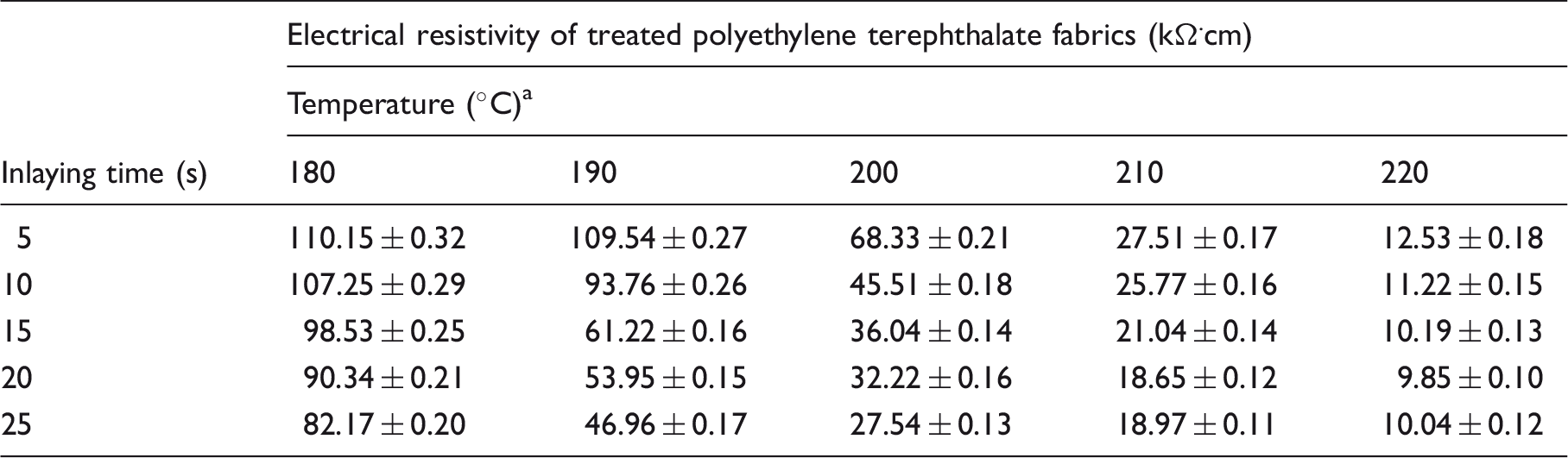
15 MPa.
Washing durability of treated PET fabric
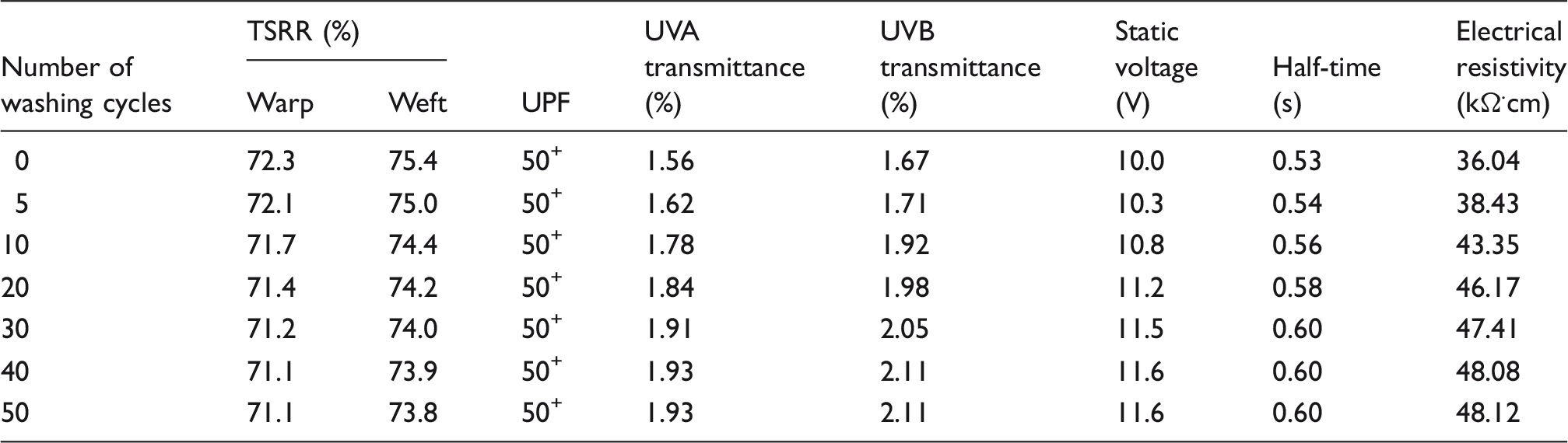
The SEM images, TSRR, UPF, UVA transmittance, UVB transmittance, static voltage and its half-time, and electrical resistivity of the PET fabric inlaid with graphene nanoplatelets at 200℃ and 15 MPa for 15 s, after varying washing cycles, are shown in Figure 10 and Table 5. As demonstrated in Figure 10, compared with the non-washed GI PET fabric (Figure 10(a)), the GI PET fabric changed very little after 50 cycles of washing (Figure 10(b)), and only the embossments on the fibers were washed off. The warp and weft TSRRs of the GI PET fabric were maintained at over 70.0% after washing for 50 cycles. In addition, the UVA and UVB transmittance of the GI PET fabric increased from 1.56 to 1.93% and 1.67 to 2.11% (Table 5), respectively. Although the transmittance increased slightly, the UPF of the GI PET fabric remained at 50+. These data indicate that the GI PET fabric continued to exhibit satisfactory UV protection. Meanwhile, the static voltage and its half-time for the GI PET fabric increased from 10.0 to 11.6 V and 0.53 to 0.60 s, respectively, and the electrical resistivity of the GI PET fabric increased from 36.04 to 48.12 kΩ.cm (Table 5). Nevertheless, the GI PET fabric retained wonderful anti-static properties. Thus, the GI PET fabric emerged as having excellent durability.
Scanning electron microscopy images of graphene-inlaid polyethylene terephthalate fabrics before (a) and after (b) 50 washing cycles. Washing resistance of graphene-inlaid polyethylene terephthalate fabric TSRR: tensile strength retention rate; UPF: ultraviolet protection factor; UVA: ultraviolet A; UVB: ultraviolet B.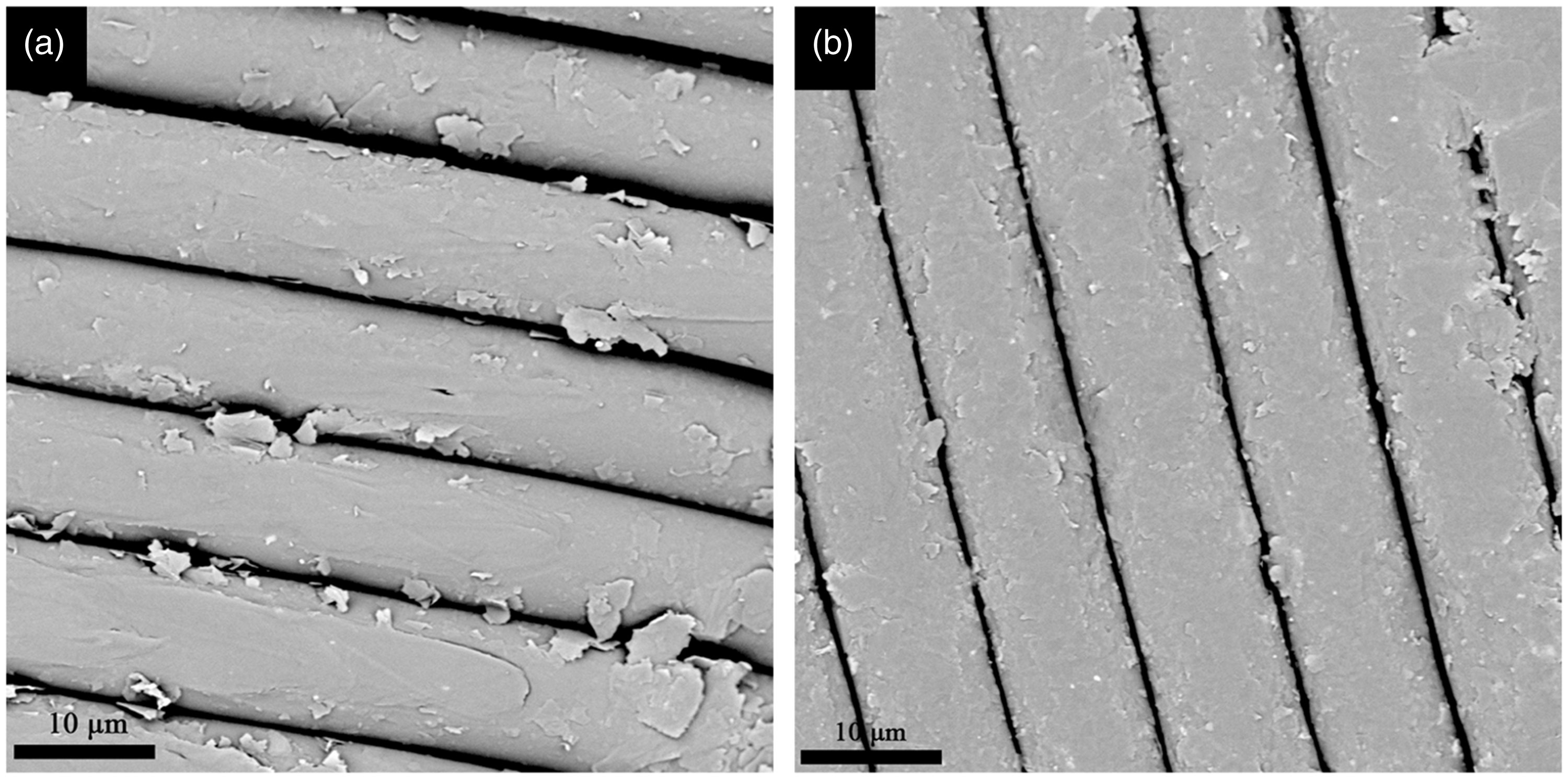
Conclusions
The graphene nanoplatelets were applied to the PET fabric surface via ultrasonic treatment in a water-bath. Then, the graphene-coated PET fabric was treated at high temperature and high pressure to inlay graphene nanoplatelets into the surface of the PET fibers. Afterwards, the GI PET fabric was cured at 100℃ for 5 min. The optimal inlaying conditions were as follows: inlaying temperature 200℃, inlaying pressure 15 MPa and inlaying time 15 s. The GI PET fabric obtained under the optimal inlaying conditions exhibited admirable anti-ultraviolet and anti-static properties. The electrical resistivity, and the peak values of the static voltage and its half-time of the GI PET fabric decreased drastically, indicating that the anti-static properties of the fabric were considerably improved. The UPF of the GI PET fabric reached 50+. The GI PET fabric retained excellent anti-static and anti-ultraviolet properties even after 50 laundering cycles. This means the GI PET fabric possesses good durability. Moreover, the breaking strength of the GI PET fabric was maintained beyond 70.0% of that of the original PET fabric. These findings show that our novel high-temperature and high-pressure inlaying method is an eco-friendly technique that requires no chemicals other than ethyl alcohol.
Footnotes
Acknowledgements
We thank the Chongqing Engineering Research Center of Biomaterial Fiber and Modern Textile for providing a good experimental environment.
Declaration of conflicting interests
The authors declared no potential conflicts of interest with respect to the research, authorship and/or publication of this article.
Funding
The author(s) disclosed receipt of the following financial support for the research, authorship, and/or publication of this article: This research was supported by the Fundamental Research Funds for the China Central Universities (Grant Number XDJK2017D044).
Graphical abstract