
Abstract
Stab and puncture resistant body armor is widely used by the law enforcement personnel, security and military in many countries. The primary requirement for the armor is to provide protection against various weapons used in an attack. Comfort properties are given increased importance in many countries and considered the second most important requirement. In this research Kevlar was blended with wool and wool–nylon. The resultant fabrics were coated with silica and their stab and puncture resistance in quasistatic conditions was examined using the universal tensile tester. It was hypothesized that the application of coating will generate higher friction to restrict the lateral movement of yarns, and thus present a higher number of yarns for direct resistance to impact during the attack and dissipating the impact energy, whereas the use of wool and nylon will provide the required ergonomics of wearability and stretch. It was observed that the application of the silica coating helped in improving the resistance to the stab and punctures using weapons such as knife (P1, as specified in NIJ 0115.00), ball and pointed impactors. In the quasistatic tests, the highest value of the maximum resistant force was recorded when the ball was used and the lowest was observed for the knife. Furthermore, the application of coating helped in absorbing impact energy. However, the fabric stiffness increased due to the coating, which will negatively impact the ergonomics and wearability.
Stab attacks on law enforcement, security and military personnel while on duty are of particular concern in European and Asian countries.1,2 Stab attacks are those where stabbing weapons such as knives are used. 3 The two types of stab weapons used by assailants are edged weapons and pointed weapons. 4 Edged weapons (such as knives) contain a long, continuous cutting edge, 5 whereas pointed weapons (such as spikes, ice picks, screw drivers and awls) have a slender rod with a pointed tip. 6 Generally, stab-resistant body armor is worn by these personnel to protect them from potential attacks. As the edged and pointed weapons differ in size, material, mass and geometric configuration, one specific body armor may not be sufficient to provide adequate protection from different threats. Hence, when designing the body armor the types of threat should be carefully considered.
Depending on the type of material used, body armor can be broadly divided into two categories: hard and soft body armor. Hard body armor is made from rigid materials such as ceramics, reinforced plastics, metal plates, and composites. The level of protection provided by hard body armor is greater than that of soft body armor. However, hard body armor is generally heavier to wear and provides less flexibility in body movement than soft body armor. Soft body armor consists of many layers of high-performance materials produced from ballistic fibers. High strength and low extension, that is, high modulus, are the most important properties of these fibers.7,8 Law enforcement officers and military personnel may wear hard body armor when there is a high level of threat. In general, for day-to-day use soft body armor is preferred as it is normally more flexible, while providing adequate protection.
High-performance fibers with high tensile strength, toughness and cut resistance make ideal candidates for stab and puncture-resistant material. 9 Though the most important requirement sought is protective performance, ergonomics of wearability is given increasing importance.10–12 Flexible woven textile structures can meet thermal comfort and wearability requirements. However, their protective performance may not be adequate with bare woven fabrics. 13 Approaches such as the application of coating, lamination, and shear thickening fluid (STF), as well as making the fiber into composites, can be adopted to improve their cut-resistance performance.14–19
Many current research studies focus on coating and impregnation methods to improve fabric performance against stab and spike attacks.6,18,20–25 Fabrics can be treated with a thermoplastic or thermosetting resin to form a stabilized material with far greater resistance to cutting, as fiber-parting of untreated fabric is minimized. The coating can be applied on one side of the fabric or the fabric can be totally impregnated with a resin, such that the fabric becomes one ply of fiber-reinforced resin, as in structural composite materials.
Several researchers have found that an increase in stab and puncture resistance can be attributed to an increase in the friction between yarns and the penetrating weapon, as well as in inter-yarn friction within the fabric system achieved by different approaches.26, 27,28 Application of coatings or other chemical treatment can lead to superior performance during penetration by various weapons. Higher friction can result in higher energy absorption due to the restricted movement of the yarns. Hassim et al. observed that strong and flexible natural rubber latex (NRL) coating restricted fiber movement in the yarn. 23 The NRL coating appeared to have significantly absorbed the impact energy due to a high frictional force and extension of the NRL film. The coefficient of friction was found to be 0.9 to 1 for the coated fabric and 0.4 for the uncoated fabric.
Although earlier research studies have analyzed the stab and puncture resistance results of fabrics made of high-performance fibers, there has been limited investigation on the use of natural fibers such as wool to increase comfort properties. Furthermore, studies on the ergonomics of wearability have not been reported. 29 Because wool can manage moisture and provide thermal comfort, this study focused on the use of wool and measurement of stiffness of the body armor materials.
One of the major factors affecting armor wearability is the material’s flexibility, which can be evaluated by the measurement of stiffness. Armor flexibility is desirable as it allows the armor to conform to and move with the body of the wearer. 30 The wearability of the body armor is influenced by the flexibility of the materials used, which can be evaluated by measuring the bending length (flat and loop test), bending angle, stiffness and buckling load for single layer fabric. 31 However, these methods may not be appropriate for measuring the stiffness of multi-layered panels of body armor, as the panel may not bend freely during the test. Furthermore, all the tests need test specimens of a particular dimension and it would be more appropriate to test a range of sizes for body armor.
The objective of this paper was to evaluate stab and puncture resistance of coated and uncoated Kevlar–wool (KW) and Kevlar–wool–nylon (KWN) fabrics. To improve the stab and puncture resistance of the fabric samples, abrasive silica coating was applied to the fabric using the traditional knife coating method. The stiffness was evaluated using standard test methods in addition to the performance evaluation after coating by using impactors such as the PI knife (NIJ 0115.00), ball and pointed objects.
Experimental details
Materials
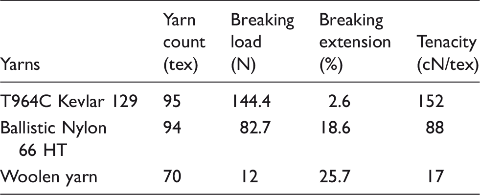
Specification of yarns used for the preparation of fabric samples
Constructional details of the fabric samples
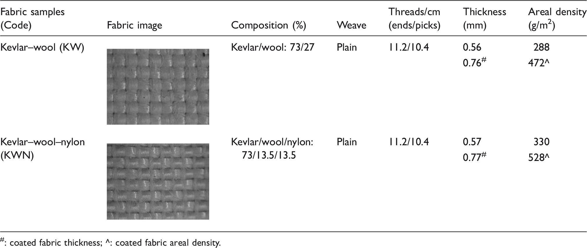
#: coated fabric thickness; ^: coated fabric areal density.
Methods
Evaluation of fabric physical properties
The fabrics were evaluated in greige form for physical as well as performance properties. Unless specified, all the test specimens were conditioned in the standard testing atmosphere (temperature = 20 ± 2℃ and relative humidity (RH) = 65 ± 5%) before performing any test. 32 All the specimens were stored and handled in black plastic bags to avoid any possible degradation from ultraviolet (UV) light.
Thread density (i.e., ends/cm and picks/cm) was measured by using a pick glass as per AS 2001.2.5 standard (determination of the number of threads per unit length in woven fabric). The weight per unit area (g/m2) was measured by using a circular specimen of 100 cm2 area as per AS 2001.2.13 standard test method (determination of mass per unit area and mass per unit length of fabrics). Fabric thickness was measured using a thickness gauge as per the ASTM D1777–96 (2011) standard. The details of the constructional parameters of the fabrics are shown in Table 2.
Fabric coating
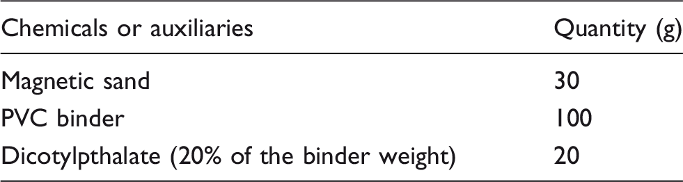
The silica used for this study was purchased from Activa in Melbourne with an average size of 242 µm (see Figure 1). It was mixed with a polyvinyl chloride (PVC)-based binder to coat the fabric samples. The silica was selected for this research based on previous findings where silica coating was successful in increasing impact energy absorption, due to the increase in frictional force.27,33 In preliminary experiments, several commercial binders such as polyurethane acrylate, Acrytex EML and Ebecryl 2002 were tried and tested for performance. However, silica coating with PVC binders performed to the maximum extent to prevent the penetration of the stab and puncture weapon. Hence, the PVC binder was selected for the research. The recipe used for preparing the coating paste shown in Table 3 was established by the preliminary experiments.
SEM images of: (a) silica (average silica particle size = 242 µm) and (b) silica coated fabric. Chemicals and auxiliaries used for fabric coating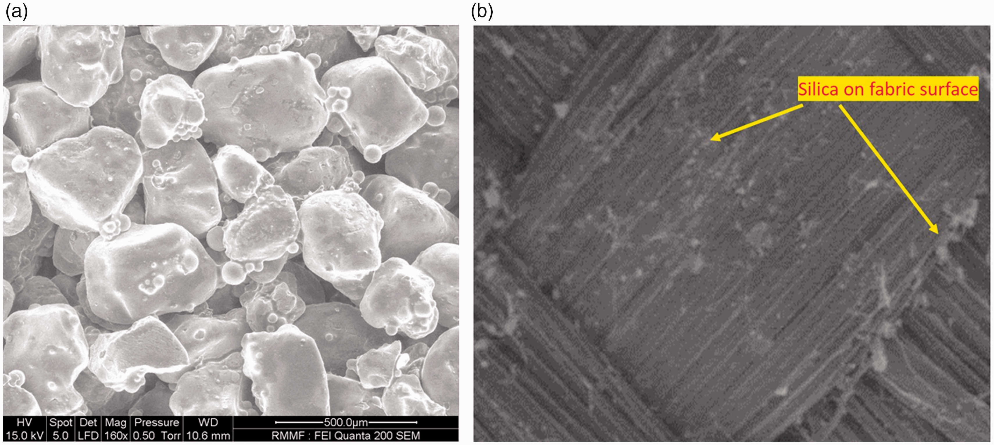
PVC binder was mixed with dicotylpthalate to prepare a uniform coating paste, before adding sand particles. Sand was then added to the coating paste, with continuous stirring to avoid the formation of any agglomerates. The fabric samples were coated using the lab scale knife-edge coater at RMIT University. The coating was applied by gradually moving the knife unit forward until the end of the traverse. Then the knife unit was driven to the start point by slightly lifting the knife. This was repeated 2–3 times to produce a uniform coating on the fabric surface. The presence of the silica in the coated fabrics can be observed from the white layer of deposition in the coated fabrics in Figure 1(b).
The coated specimens were dried for 30 min in a hot air-drying chamber set at 60℃. A laboratory-scale steamer (manufactured by Werner Mathis) was used for the fixation of the coating. The equipment contained a steam atmosphere with temperature and humidity controls. The period of coated sample exposure was controlled using an integrated timer for 5 minutes and the curing temperature was set to 180℃ for Kevlar–wool fabrics and 170℃ for Kevlar–wool–nylon fabrics.
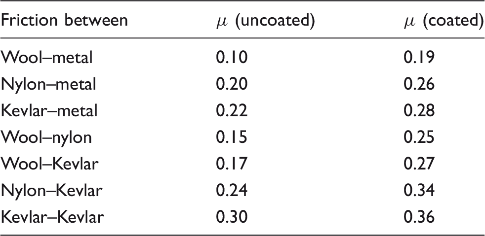
Yarn to yarn and yarn to metal friction
Yarn to yarn and yarn to metal friction was measured using the setup shown in Figure 2(a). An Instron tensile tester (Instron, model: 3300) was used to pull the yarn over two horizontal rods (diameter 20 mm) mounted to an upright wooden plate, as shown in Figure 2(a). The input yarn tension was controlled by a weight (W = 70 g) and the number of wraps of the yarn (=1). The output tension (T), was measured by the load cell of the Instron tensile tester, which was determined from the load–extension curves, as shown in Figure 2(b). The average of four load readings when the load was stabilized was taken for calculation. The coefficient of yarn to yarn and yarn to metal friction was measured by aligning the yarns on the rods as shown in Figure 2(a) and pulling the yarn at 90° to the rods. The coated yarn friction was measured by using the yarns removed from the coated fabrics. Yarn to metal friction was measured when the yarn was pulled only on the metal surface.
Experimental setup used to measure yarn to yarn and yarn to metal friction (a) experimental setup and (b) load–extension curves.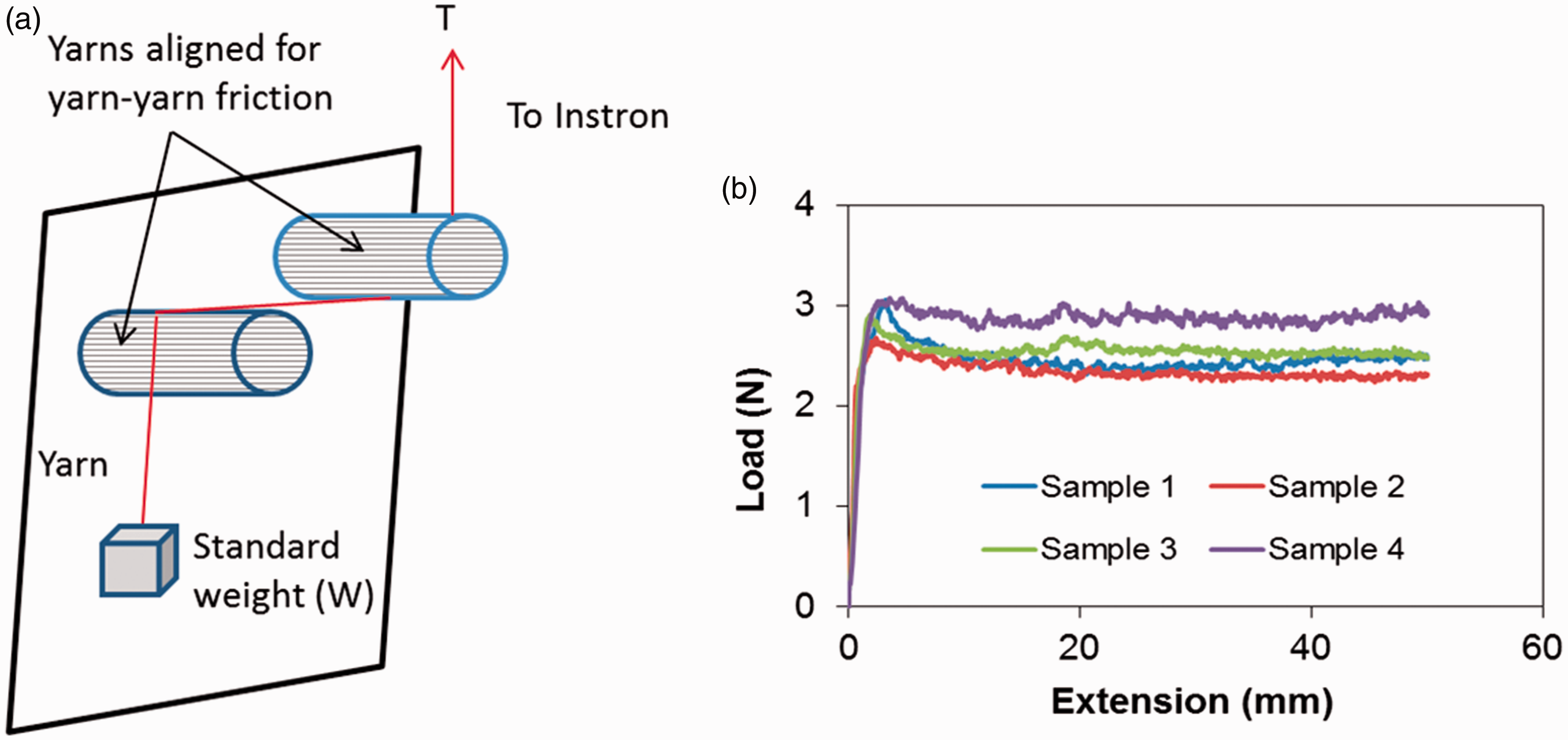
The coefficient of friction (μ) was calculated by using the formula shown in equation (1).
Scanning Electron Microscopy (SEM)
The damage profile of the tested fabric samples was analyzed by Field Emission Scanning Electron Microscopy (Philips XL30 FE-SEM). The SEM was performed with an accelerating voltage of 15 kV in low vacuum mode. The test samples were placed on stubs and coated with gold by using a high-resolution ion beam sputtering system. The particle size of the silica was also analyzed from the SEM images using IMAGE J software.
Evaluation of fabric stiffness
Fabric stiffness was measured in warp and weft directions of the fabric as per ASTM D 1388-2014 (standard test method for stiffness of fabrics). The cantilever test method was followed. The method employs the principle of cantilever bending of the fabric under its own weight. The schematic of the principle of cantilever testing and the stiffness tester are shown in Figure 3.
Fabric stiffness testing: (a) principle of stiffness testing (l = bending length and θ = bending angle) and (b) stiffness tester.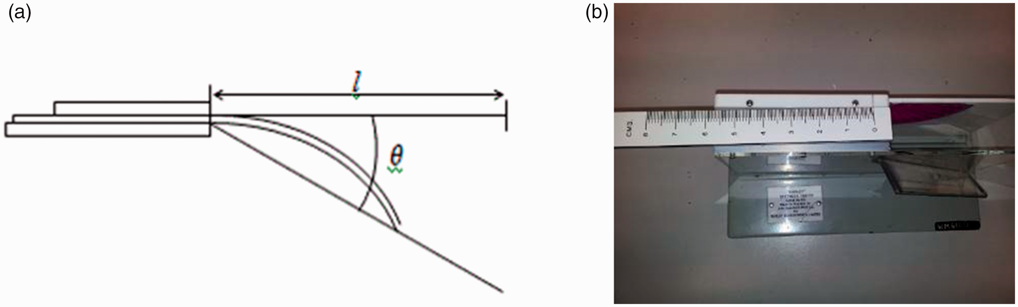
Bending length and flexural rigidity values were calculated from five specimens in each direction (warp and weft) for each fabric sample on both the fabric face and back side. The flexural rigidity (G in µJoule/m) was calculated from equation (2).

Quasistatic stab and puncture tests
Test parameters used in Instron for quasistatic stab test
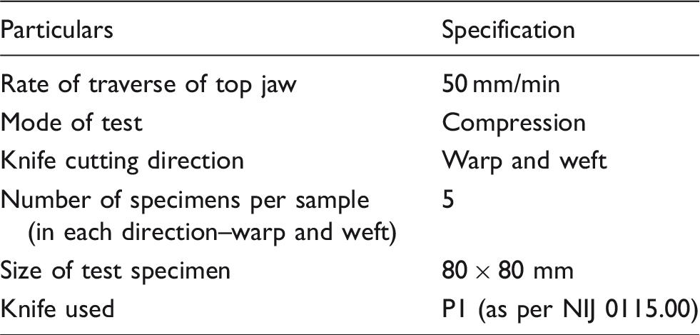
The test setup used in the Instron for the quasistatic stab test is shown in Figure 4. The P1 knife (as specified in NIJ 0115.00) was securely mounted onto the top jaw of the Instron and the fabric was firmly held by the specimen holder, as shown in Figure 4(a). During the quasistatic test, the knife penetration commenced with the tip of the knife just touching the fabric surface (Figure 4(b)). Modified quasistatic stab and puncture tests were also performed by several researchers, based on similar principles but with different settings.15, 34–36
Stab testing setup on Instron: (a) specimen mounting on Instron and (b) knife tip touching the fabric surface before the test.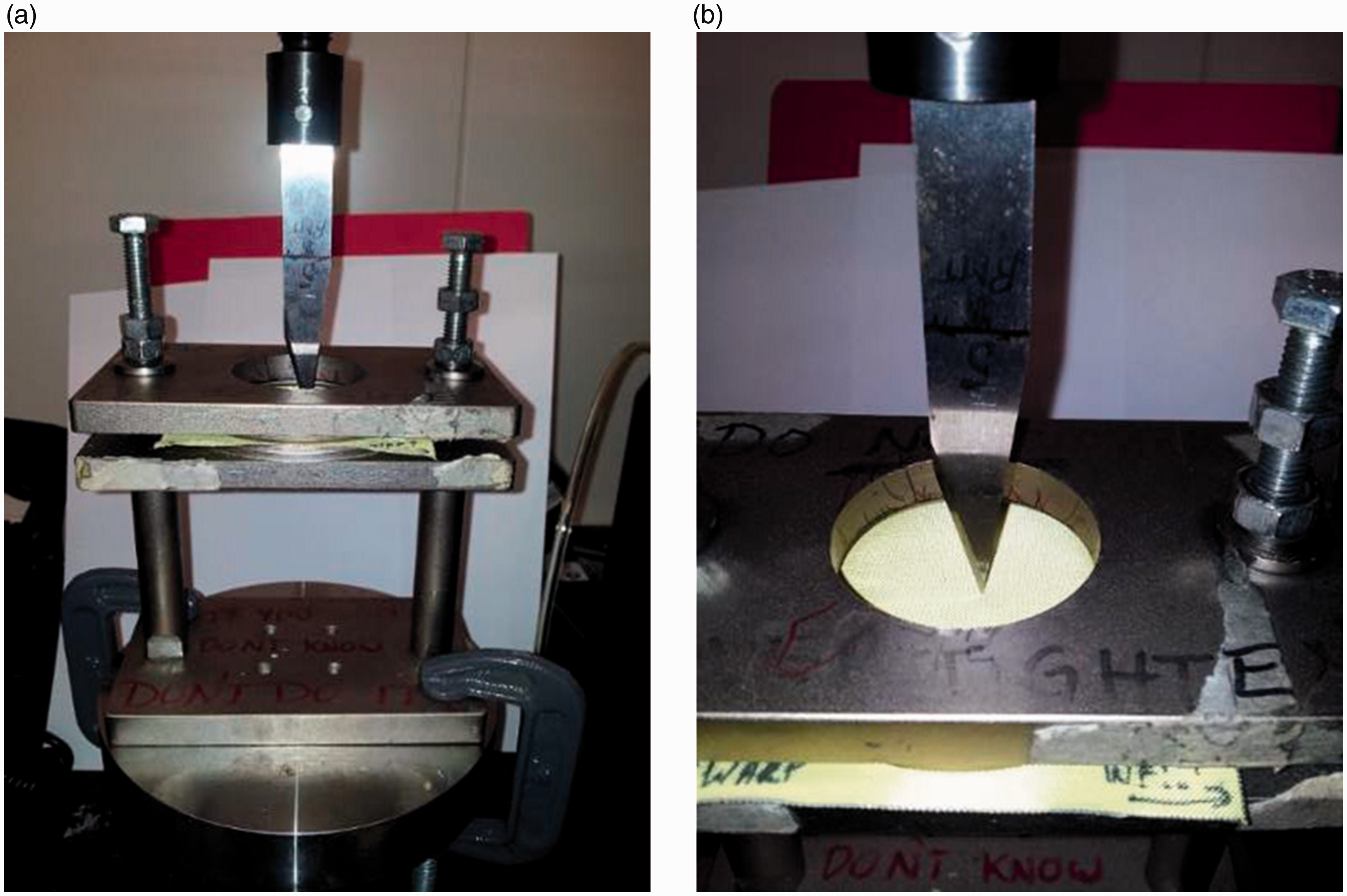
The knife was allowed to penetrate up to 53 mm (the point where the cutting edge of the knife ends, as shown in Figure 5(a) and (d)) perpendicular to the warp/length or weft/width and the test was completed at this point. The mean and standard deviation of the maximum load for five specimens in each direction were calculated and the results were presented graphically.
Objects used for stab tests: (a) and (d) – NIJ knife (P1); (b) and (e) – 10 mm ball; and (c) and (f) – pointed impactor.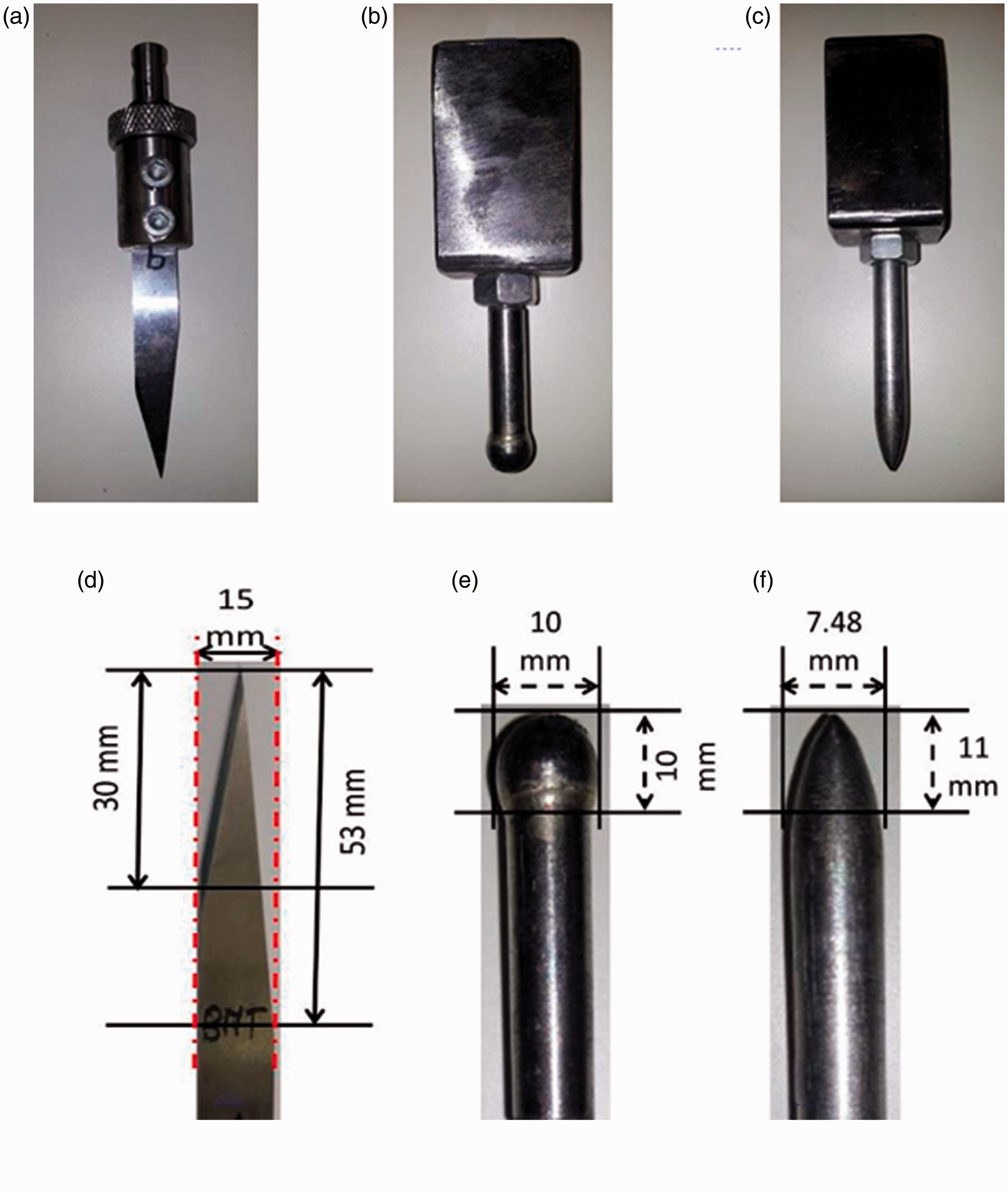
In addition to the maximum load, the energy needed by the knife to rupture through the specimens was calculated from the depth of knife penetration of 30 mm and 53 mm (see Figure 5(d) for the knife profile). The energy was calculated from the load–extension curve by multiplying the instantaneous load and the extension interval, then adding them to get the total energy.
Similarly, the puncture resistance was measured using the impactors (10 mm ball and pointed impactor) as shown in Figure 5(b) and Figure 5(c) using the same Instron set up as used for the stab tests. The maximum load was noted from the compressive load–displacement curve, whereas the energy needed by the impactors to completely rupture through the specimens was calculated from the load–displacement curve by multiplying the instantaneous load and the extension interval, and then adding them to get the total energy.
Statistical analysis
Statistical analyses were performed on the quasistatic test results, friction and stiffness properties using the single factor analysis of variance (ANOVA) in Excel 2010 (p ≤ 0.05). The analysis was performed to examine whether there were statistically significant differences among the mean values of the samples for the properties. The difference between the fabric test results was significant when the F value was larger than Fcritical. The F value is the ratio of two mean square values, whereas the Fcritical of the test results must be exceeded by the F value to reject the null hypothesis. A higher F value results in greater variation among group averages.
Results and discussion
Physical and frictional properties
Fabric constructional parameters are shown in Table 2. It can be observed from the table that the areal density of the KWN fabric was higher than that of the KW fabric. However, both fabrics had similar thickness values. Furthermore, both thickness and the weight of the samples were increased after coating the samples. The increase in the weight of the samples due to coating was 64% and 60%, respectively, for KW and KWN fabric (Table 2). Similarly, thickness values were increased by 35.7% and 35.1% for KW and KWN fabric, respectively.
Coefficient of friction for yarns
Bending length and flexural rigidity
Fabric samples were evaluated for stiffness properties to investigate the change in their flexibility with the application of coating. The flexibility of the armor material plays an important role in the dexterity of body movement when the armor is used. The flexibility test results provide an indication of the stiffness of an armor system. The lower is the stiffness; the higher the flexibility of the armor system and vice versa. Higher flexibility values will facilitate the ergonomics of wearability. The stiffness values in terms of flexural rigidity are shown in Figure 6 and Table 6.
Flexural rigidity of fabric samples. Flexural rigidity of fabric samples in (µJ/m)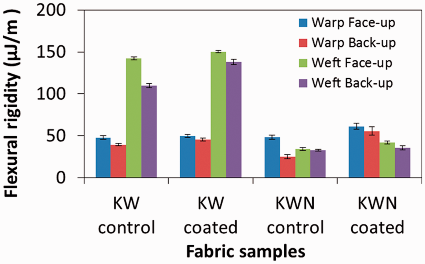
It can be observed from Figure 6 that the flexural rigidity of the coated samples was higher than that of the control samples, which was statistically not significant (F for KW = 0.1, F for KWN = 3.1, Fcritical = 5.99 at p < 0.05) except for KW weft back. The changes in the fabric stiffness values can be attributed to the additional stiffness provided by the coating to the fabric surface. As the performance of the armor materials is the primary factor, the minor increase in the stiffness can be acceptable if the values fall below a certain threshold. Furthermore, the flexural rigidity of the fabric samples tested face-up was higher than for back-up, irrespective of the fabric type. This can be attributed to the presence of the coating on the fabric face. In the case of KW fabric, the weft flexural rigidity was significantly higher than the warp flexural rigidity (F = 7.3, Fcritical = 6.6 at p < 0.05). This can be attributed to the high stiffness of Kevlar compared with nylon. However, in the case of KWN fabric, the warp flexural rigidity was higher than the weft fabric.
Quasistatic stab results
Graph profile
The stab resistance force as a function of knife penetration depth in warp and weft direction is shown in Figure 7. It is evident from the nature of the curves that there are multiple peaks and troughs during the stab tests of both the coated and uncoated fabrics. In the initial stage of the test, the tip of the knife blade is engaged with the fabric and starts tensioning the yarns and fibers, followed by the cutting action.
9
Hence, the value of force required by the knife gradually increases until it reaches the first peak. Once the first peak is reached, there is a sudden drop in the force, which can be attributed to the fact that: (a) the knife width remains the same for a short length and (b) the knife only enters through already cut fabric without experiencing much resistant force. The force needed for penetration depends on factors such as the knife geometry, thickness, tip radius and knife cross section.37,
38
Subsequently, after a sudden drop in the load, as the knife penetration continues, the width of the knife blade increases (Figure 5(a)). The knife now needs to cut additional threads, leading to an increase in the force value until it reaches the second peak followed by a sudden drop in recorded force. This phenomenon continues, and multiple peaks and troughs are shown during the quasistatic stab test, as shown in Figure 7.
Stab resistance force as a function of depth of knife penetration: (a) warp direction and (b) weft direction.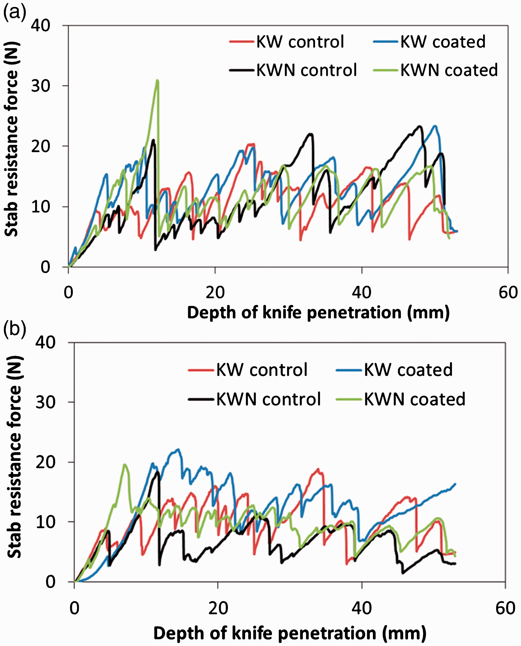
Maximum load and energy absorbed
Maximum load and energy absorbed values for stab tests
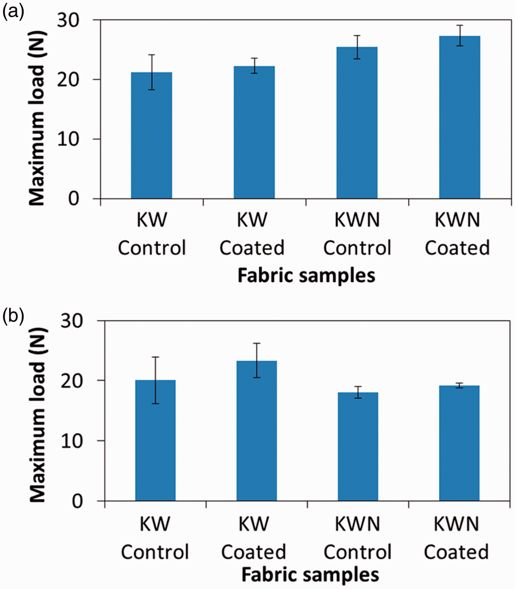
Maximum knife penetration load values: (a) warp direction and (b) weft direction.
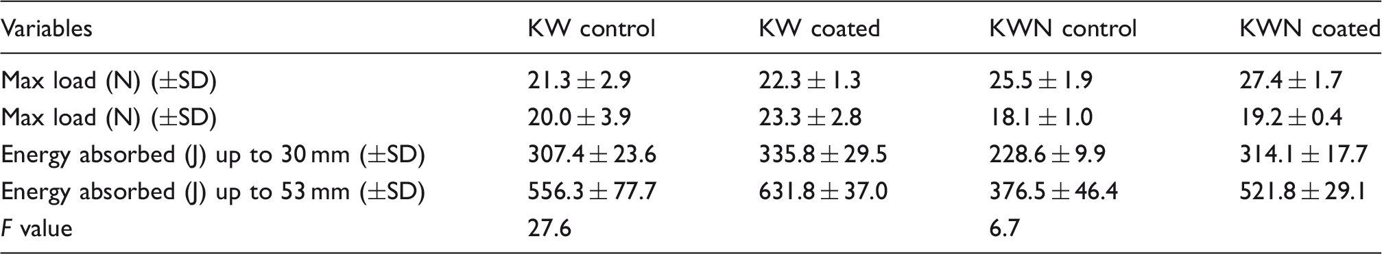
The coated samples showed higher maximum penetration resistant load values than their corresponding control samples irrespective of the fiber type and direction of test, which can be attributed to the extra protection provided by the coating on the fabric. The abrasive silica particles blunt the knife; hence, they reduce the depth of penetration. The maximum load values were increased by 5.0% for KW fabric and 7.3% for KWN fabric in warp direction after the coating was applied. Similarly, in weft direction, these values were 16.4% and 6.0% for KW and KWN fabric, respectively. The increase in the maximum load values can be attributed to the increase in the yarn to yarn and yarn to metal friction after the coating was applied. 28 The difference between the results were statistically significant in weft direction for both samples (F = 27.6 for KW, F = 6.7 for KWN, at p < 0.05).
The amount of energy absorbed by the fabric samples in warp and weft direction during the quasistatic stab test is shown in Figure 9 (up to 30 mm knife penetration) and Figure 10 (up to 53 mm knife penetration). The energy absorbed represents the energy needed to reach a required point in the displacement or X-axis (i.e. depth of penetration). This was calculated by the integral of the force–displacement curve up to the required point. The same test was performed using the knife, ball and pointed impactor (see Figure 7). In the incident of a stab or puncture attack, the energy of the knife or other impactor is absorbed by the fabric layers present in the clothing. Each clothing layer absorbs certain amount of energy depending on the fiber type, fabric structure, number of fabric layers in the clothing, areal density and the nature of the knife. Furthermore, the yarn to yarn friction and the friction between the fabric and the knife affect the amount of energy absorbed. The higher the amount of energy absorbed by the clothing layer, the lower will be the impact of the knife or the other impactor on the wearer.
Amount of energy absorbed by the fabric samples during the quasistatic stab test (30 mm depth of knife penetration): (a) warp direction and (b) weft direction. Amount of energy absorbed by the fabric samples during quasistatic test (53 mm): (a) warp direction and (b) weft direction.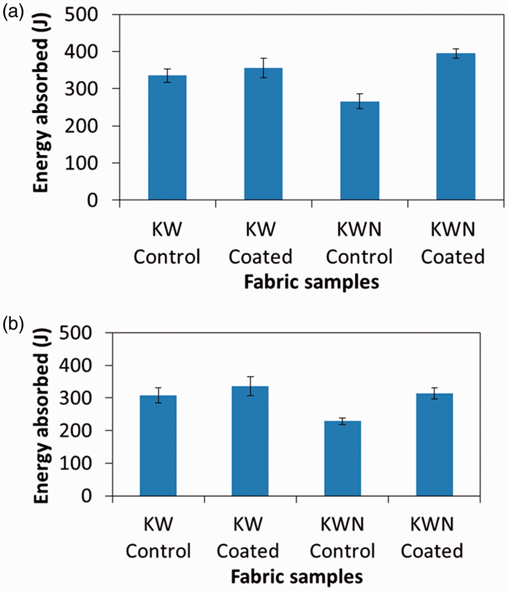
It can be seen from Figure 9 that the amount of energy absorbed during the quasistatic stab tests in warp direction were 335.3 J, 355.3 J, 266.0 J and 395.1 J for KW control, KW coated, KWN control and KWN coated fabrics, respectively. For the same tests in the weft direction these values were 307.4 J, 335.6 J, 228.6 J and 314.1 J for KW control, KW coated, KWN control and KWN coated fabrics, respectively. The coated samples recorded higher energy absorbed values than the uncoated samples. This can be attributed to the increase in the frictional resistance of the fabric samples after coating. Without the coating, the yarns in the fabric can easily slide apart with the impactor action. When the coating was applied, there was an increase in the inter-yarn friction and yarn-metal friction, which resisted the knife movement, resulting in a higher amount of energy being absorbed by them due to the binding effect of the coating. The restriction of yarn movement indicates that the knife needs to cut more yarns during the test. A similar observation has been reported by several researchers, where the increase in the inter-yarn friction has resulted in the increase in the energy absorbed up to a certain point during the test.39, 40
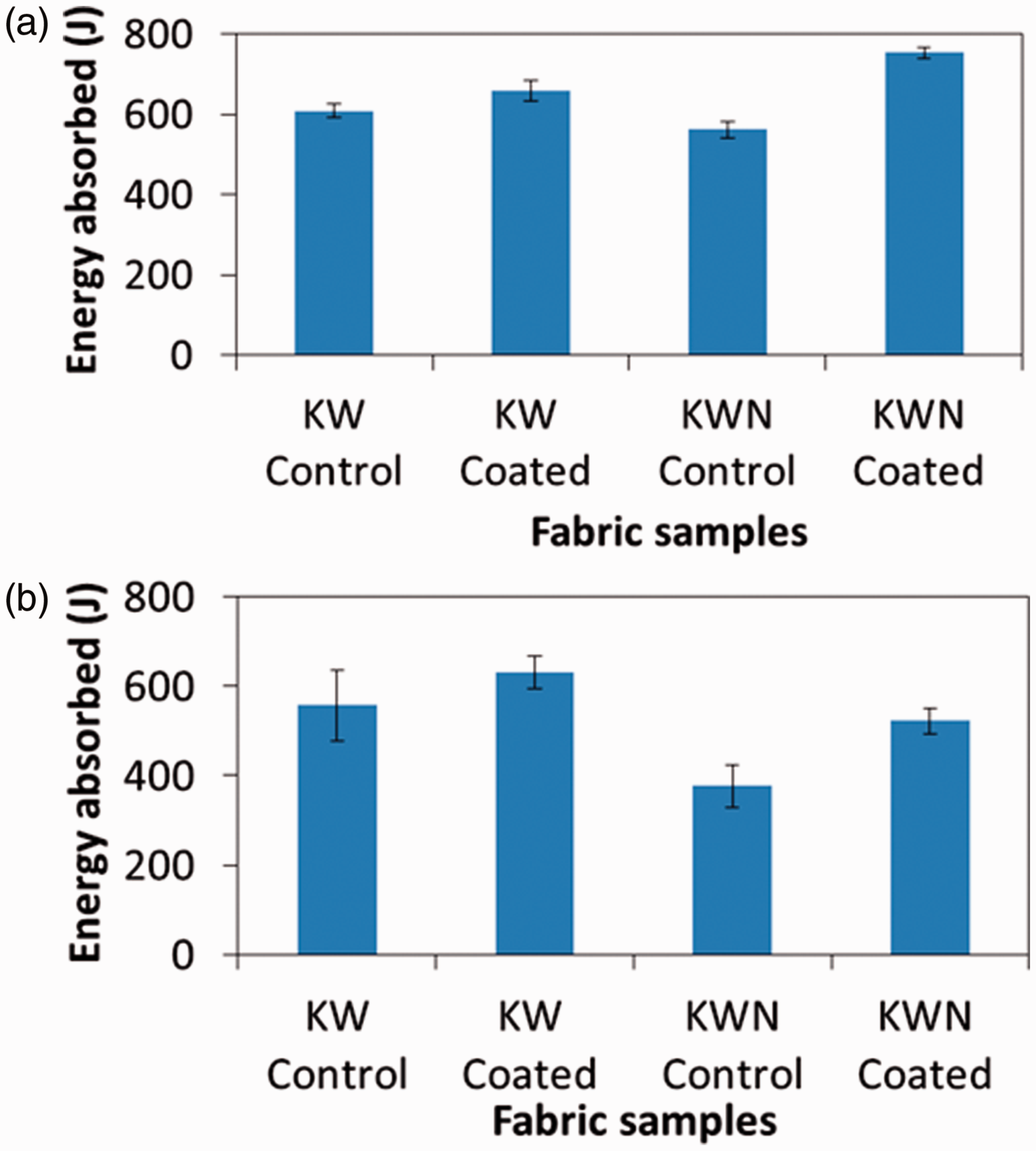
Figure 10 shows the amount of energy absorbed by the fabric samples up to 53 mm of knife penetration, which were 609.1 J, 659.7 J, 562.7 J and 753.2 J in warp direction; and 556.5 J, 631.8 J, 376.5 J and 521.8 J in weft direction for KW control, KW coated, KWN control and KWN coated fabrics, respectively. The amount of energy absorbed up to 53 mm showed similar trend to the energy absorbed up to 30 mm of penetration. The increase in the energy absorbed can be attributed to the increase in the inter-yarn and yarn-metal friction after coating. The energy absorbed was increased by 8.3% for KW fabric and 33.8% for KWN fabric in warp direction, whereas in weft direction the increase was 13.5% and 38.5% for KW and KWN fabric, respectively.
Puncture results (ball)
Graph profile
The puncture behavior of the fabric samples was analyzed by using a 10 mm ball and pointed impactor. The puncture results in terms of the compressive load and displacement using the 10 mm ball are shown in Figure 11. It is evident from the figure that the nature of the curves obtained during the quasistatic tests using the ball is substantially different compared with those using the knife. There was only one peak observed rather than the multiple peaks and troughs obtained in the case of the knife. Unlike the knife, the load was gradually increased in the case of the ball until it reached the maximum value, where the fabric completely ruptured. Once the maximum value was reached, the load dropped drastically and approached zero. From the compressive load versus displacement curve, it is evident that the nature of the curve for KW fabric was different from the KWN fabric. In the former case, the load dropped suddenly, resulting in a sharp triangular peak whereas in the latter case, a gradual drop was observed with a bent peak. The KW fabric exhibited higher extensibility compared with the KWN fabric. The tests were completed at the ball movement of 20.2 mm and 25.6 mm for KWN fabric and KW fabric, respectively, from where the load quickly dropped to zero.
Puncture resistance force VS ball displacement.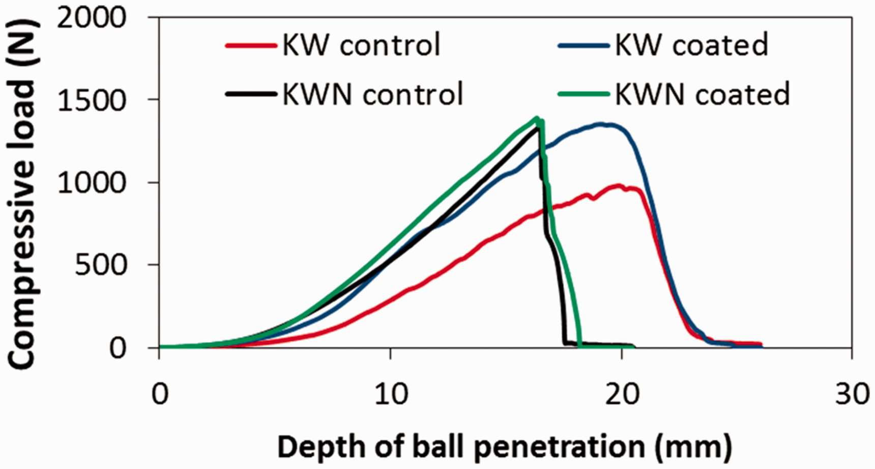
Maximum load and energy absorbed
The maximum load values for the puncture test results using the ball impactor are shown in Figure 12(a) and Table 8. It can be observed from the maximum load values that there was an increase of 19.3% and 6.8% for KW fabric and KWN fabric, respectively, after the coating was applied. The increase in the maximum load can be attributed to increased inter-yarn friction and yarn-metal friction, which tightly hold the constituent threads of the fabric and restricted the ball movement through it, resulting in higher load values. The maximum load for the ball was much higher than the knife, due to larger size of the impact point of the ball and no cutting action by the ball, compared with the knife. The maximum load values were significantly increased in the case of KW coated fabric as shown in Table 8 (F = 13.5 for KW, F = 2.3 for KWN, at p < 0.05).
Puncture test results using the ball impactor: (a) maximum load values and (b) amount of energy absorbed. Maximum load and energy absorbed values for puncture tests (10 mm ball)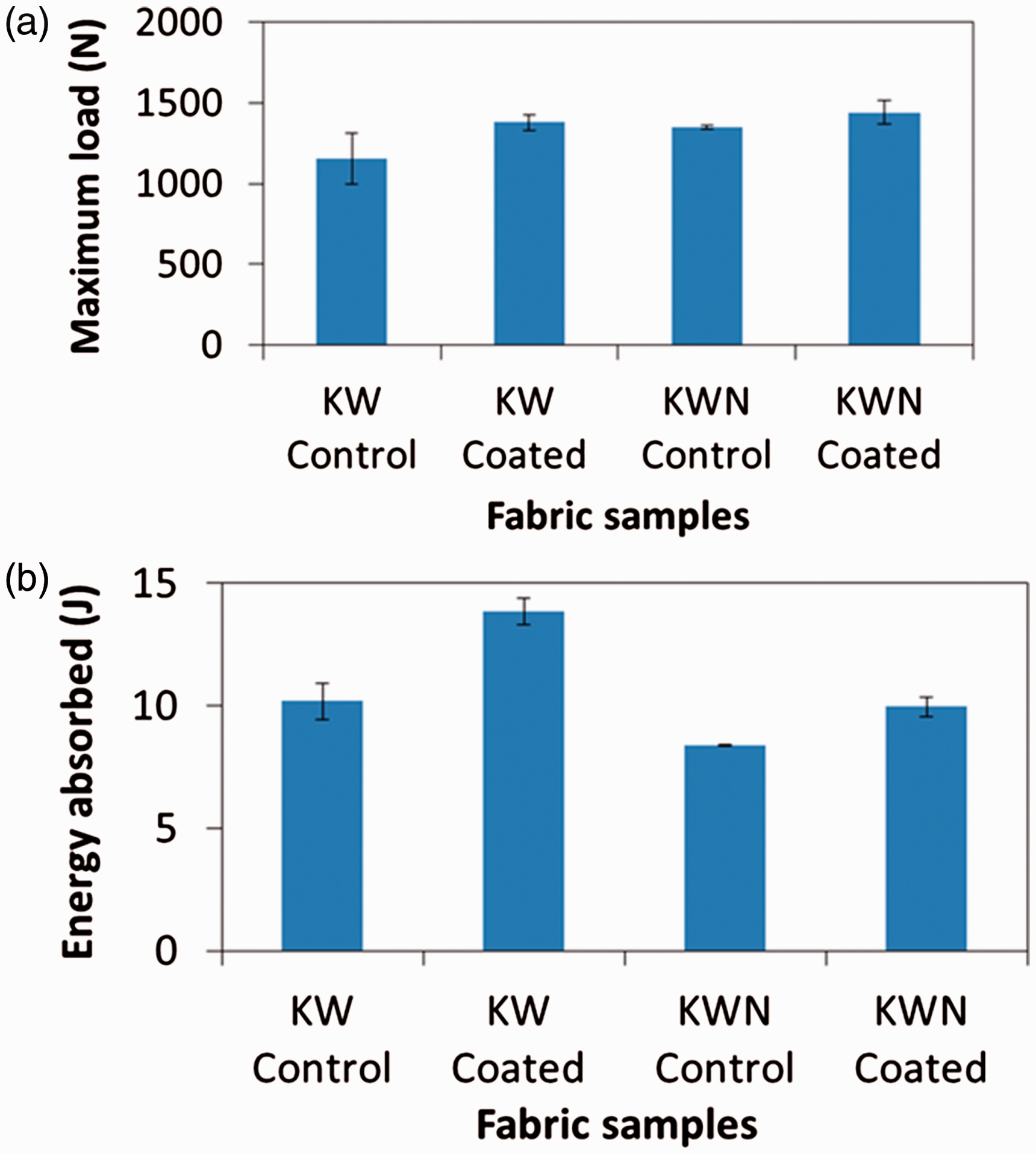
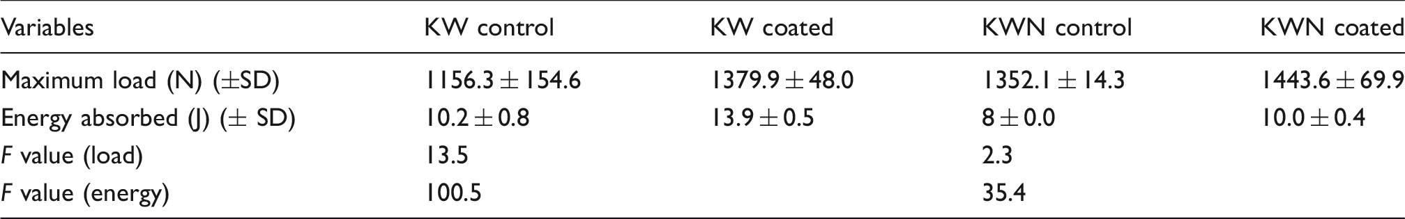
The amount of energy absorbed during the puncture test using the ball is shown in Figure 12(b). It can be observed that the energy absorbed values were 10.2 J, 13.9 J, 8.4 J and 10.0 J for KW control, KW coated, KWN control and KWN coated fabrics, respectively. The energy absorbed values were increased by 36.0% and 19.0% for KW fabric and KWN fabric, respectively, after coating. The increase in energy absorbed is due to the increase in the inter-yarn friction and yarn-metal friction after coating that prevents the movement of threads, resulting in higher energy. The energy absorbed by the ball impactor was much lower than the knife impactor. This can be attributed to the difference in the profile of the ball and the knife. The knife width increases gradually up to the depth of 53 mm, which required the knife to cut a higher number of threads. However, in the case of the ball, the work was done till the ball entered into the fabric structure. Then there was no further work done, as the fabric ruptured with the impact of the ball. The energy absorbed values were significantly increased for both the KW and KWN fabric (F = 100.5 for KW, F = 35.4 for KWN at p < 0.05).
Puncture results (pointed impactor)
Graph profile
The puncture results in terms of the compressive load and depth of penetration using the pointed impactor is shown in Figure 13. It can be seen from the figure that the nature of the compressive load–extension curve bears resemblance with the curve obtained using the 10 mm ball. It can also be observed that the load increased gradually until it reached the maximum value where the specimen was ruptured. After the specimen was ruptured, the load dropped gradually at a slower rate compared with the ball. In the case of the ball, the sudden drop in the load can be attributed to its shape. As the point of the ball has the maximum dimension, it creates an aperture in the fabric with a diameter of the ball. Hence, once the fabric fails, the ball moves without making any frictional contact with the threads in the fabric. However, when the pointed impactor is used, the impactor is still in contact with some yarns in the fabric structure after the fabric has ruptured. In the case of the ball, the load dropped to zero, however, in the case of the pointed impactor there was some residual load, which ranged from 22-100 N. The load values were recorded due to the frictional resistance of the yarns while in contact with the pointed impactor.
Puncture resistance force as a function of pointed impactor extension.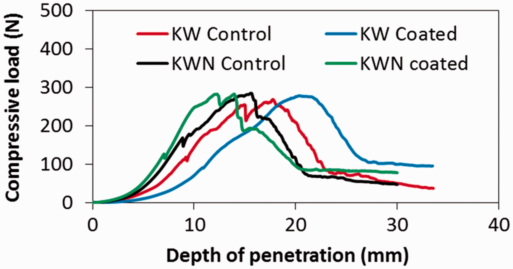
Maximum load and energy absorbed
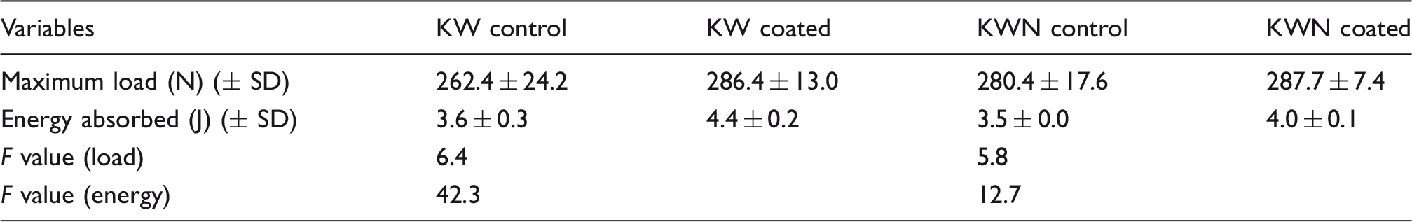
The maximum load obtained with the pointed impactor is shown in Figure 14(a). It can be observed from the figure that the maximum load values were 262.4 N, 286.4 N, 280.4 N and 287.7 N for KW control, KW coated, KWN control and KWN coated fabrics, respectively. There was an increase of 9.1% and 2.6% for KW fabric and KWN fabric, respectively, after the coating was applied. The maximum load value was statistically significant for the KW fabric (F = 6.4 for KW, F = 5.8 for KWN at p < 0.05).
Puncture test results using the pointed impactor: (a) maximum load values and (b) amount of energy absorbed.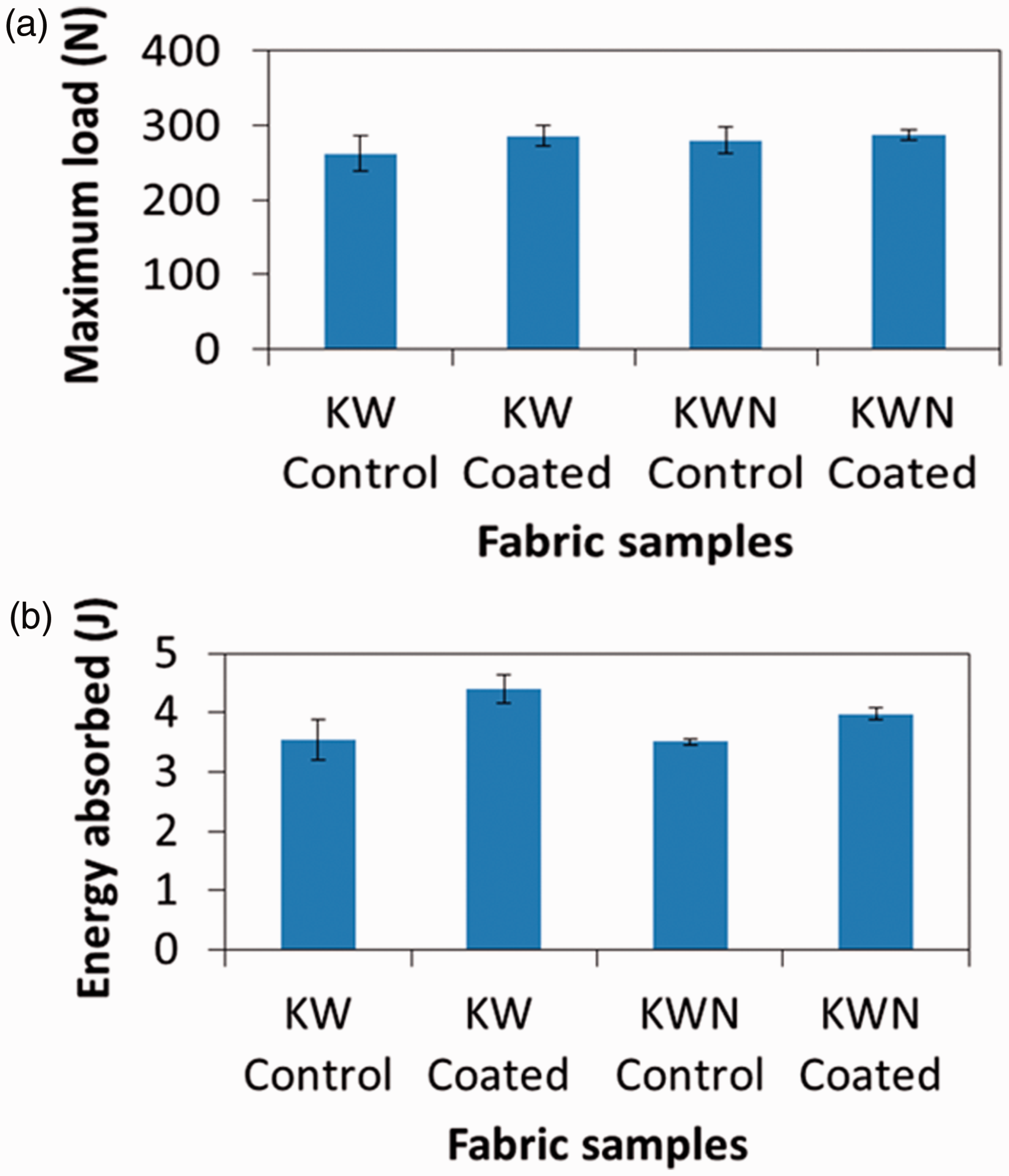
Maximum load and energy absorbed values for puncture tests (pointed impactor)
Additional observations
Maximum load and energy absorbed
It can be observed from Figure 8, Figure 12 and Figure 14 that the highest value of the maximum load was recorded when the ball was used and the lowest of the maximum resistance force was observed for the knife in the quasistatic tests. The highest maximum load for the ball can be attributed to the resistance provided by the highest number of warp and weft yarns being in contact with the ball surface, which had the highest surface area. During the quasistatic test, the ball has to penetrate through 11.2 warp and 10.4 weft threads in the case of both the KW and KWN fabric. The ball had a smooth surface compared with the knife and the pointed impactor. As the ball compressing, it kept extending this amount of yarns until the elastic limit was reached or the yarns were pushed aside. Once the elastic limit was reached, the warp and weft threads were broken. However, in the case of the pointed impactor, the sharp tip was in contact with lower number of yarns due to smaller dimension compared with the ball, which resulted in a lower maximum load. In the case of the knife impactor, the cutting action of the knife blade helped in the easy penetration of the knife into the fabric. Hence, the total resistance provided by the yarns in the fabric was much lower.
Furthermore, it can be observed from Figures 9, 10, 12 and 14 that the energy absorbed during the impact for the knife was the highest and for the pointed impactor was the lowest. The energy absorbed by the knife during the quasistatic test being highest can be attributed to the appearance of multiple peak load values recorded when the knife penetrated the fabric. In the case of ball and the pointed impactor, only a single peak was observed. This led to a smaller area under the load–displacement curve. Furthermore, in the case of the knife, the test continued until the knife penetrated 53 mm. However, in the case of the ball and the pointed impactor, the load values drastically reduced and approached zero when the fabric failed. For KW fabric, this was achieved in the range of 20–30 mm and for KWN this was achieved at about 30 mm. This phenomenon led to the lowest energy being recorded by the pointed impactor.
Test sample morphology
It can be observed from the stab morphologies (Figure 15) that the degree of yarn and fiber damage in the case of uncoated fabric (Figure 15(a) and (b)) after testing was much higher compared with the coated ones (Figure 15(c) and (d)). The uncoated fabrics can be seen to have higher yarn fraying on the fabric surface (both front and back) compared with the coated fabrics. This can be attributed to the easy movement of the yarns out of the fabric surface in the uncoated fabrics. The application of coating on the fabric surface binds the constituent fibers in the yarn together and does not allow them to move outwards. Hence, the fibers in the yarn structure and the yarns in the fabric structure stay adhered to the fabric surface rather than fraying. Similar observations were made for the KWN uncoated and coated fabrics.
SEM images of knife penetrated fabric samples: (a) KW control-front, (b) KW control-back, (c) KW coated-front and (d) KW coated-back.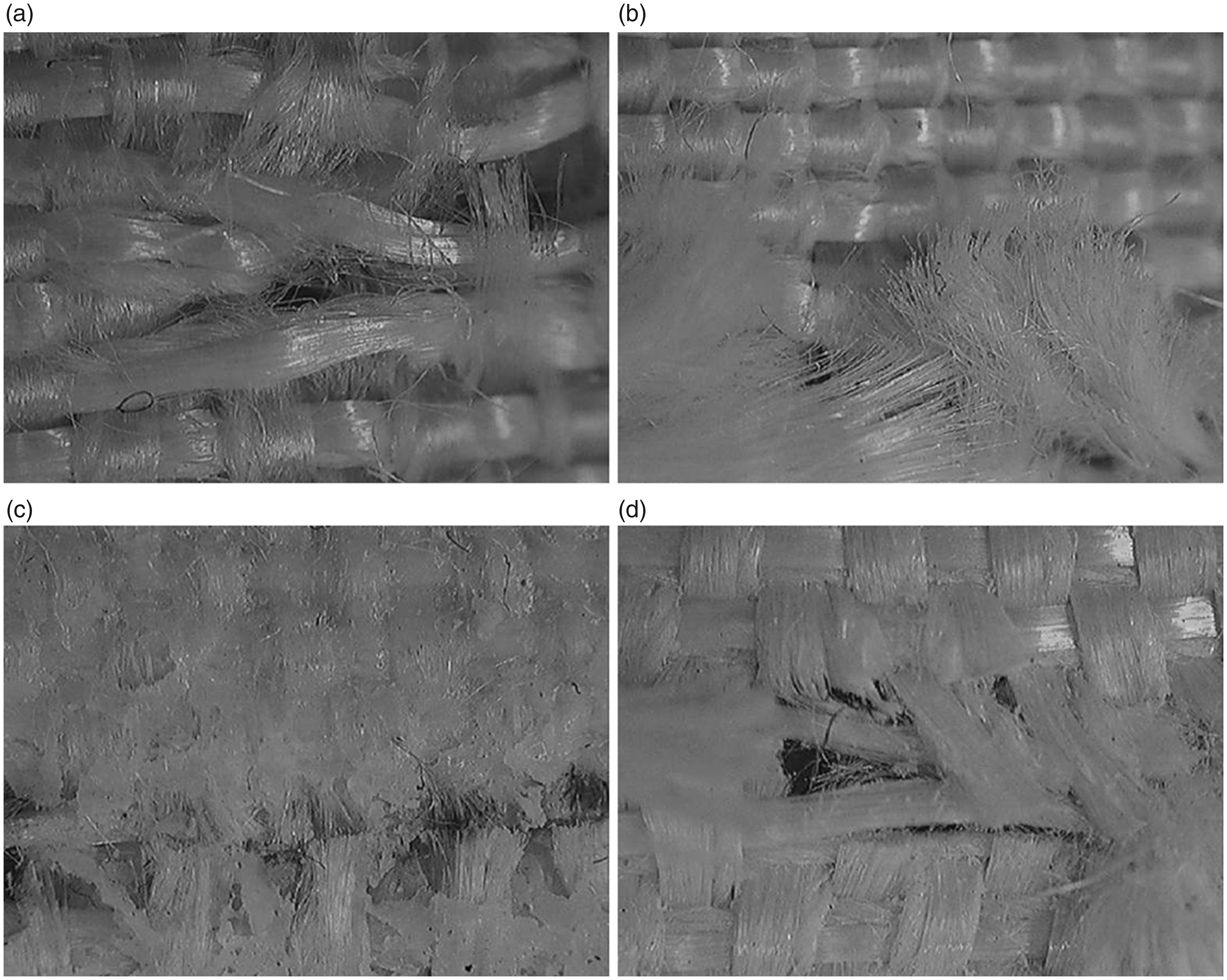
Figure 16(a) to (c) shows the image of the coated specimens after the test was completed using the knife, ball and the pointed impactor, respectively. White shaded areas were present close to the point of impact in the tested specimens. These white shaded areas are those that were strained during the test by the impactors. It can be observed that the yarns were highly strained close to the point of impact. When the impactor interacted with the fabric, the stress waves propagated in both warp and weft directions. As the impact depth increased, the strain was reduced. The white area indicates the gradual decrease in the strain away from the puncture. Furthermore, it can be observed from the figure that the area that was strained by the impactor was the lowest for the knife and highest for the ball. These strain results support the highest maximum load values being obtained for the ball and the lowest for the knife. Furthermore, the white area extends more in the warp and weft directions, indicating that the strain propagated in the direction of warp and weft, and suggesting that the constituent warp and weft yarns were highly strained during the test. The phenomenon of stress propagation in warp and weft direction during stabbing or other similar impactor was observed by several researchers.41,
42
Test samples using: (a) knife, (b) ball, (c) pointed impactor showing the propagation of strain wave around the point of impact.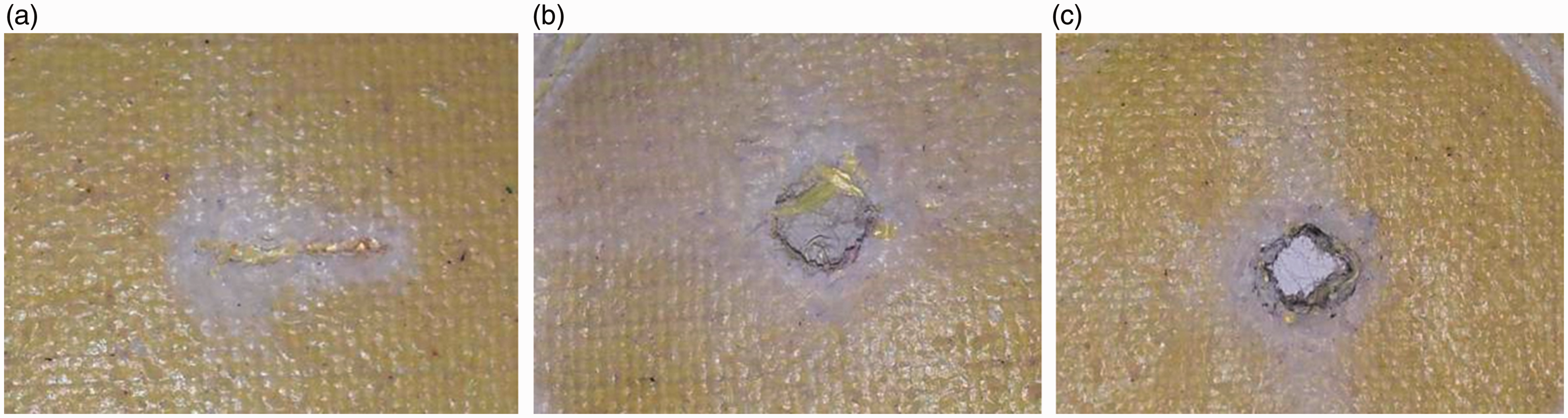
The damage profiles of the uncoated fabric samples for KW fabric with various impactors are shown in Figure 17. It can be observed from Figure 17(a) to (c) that the damage profiles of fabric samples are different depending on the impactor. In the case of the knife, the sharp edges cut the threads as it entered through the fabric structure. Hence, a fine slit can be observed in both the front and back of the fabric. However, in the case of the ball and the pointed impactor, the mechanism of penetration was entirely different. When the ball or the pointed impactor entered the fabric structure, it mechanically strained the warp and weft threads that were in contact, until they reached their final breaking point. A number of warp and weft threads were broken and projected outwards from the fabric surface, mainly to the back of the fabric.
Damage profiles of fabric samples with different impactors: (a) and (d) – knife impactor; (b) and (e) – ball impactor; and (c) and (f) – pointed impactor.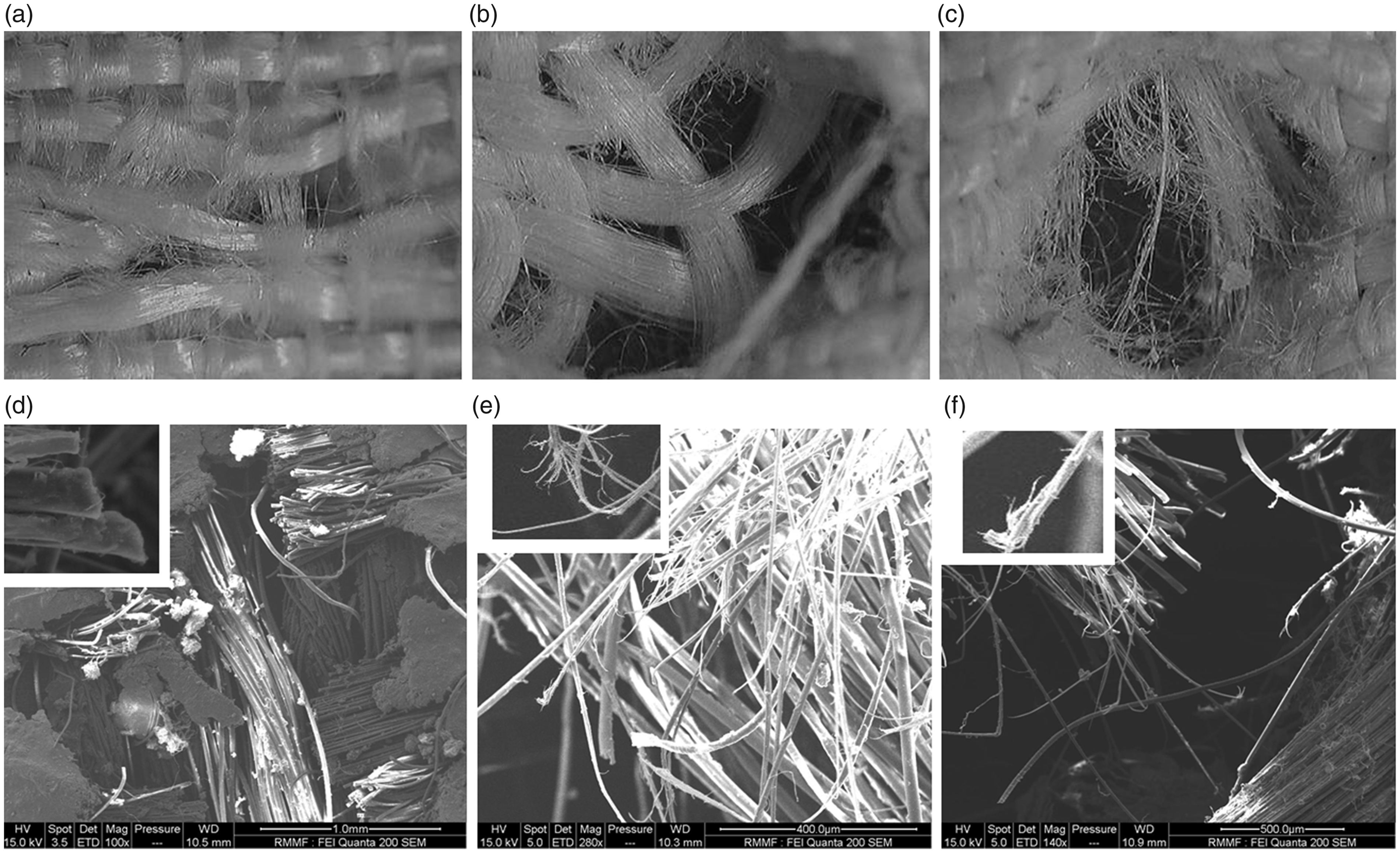
Figure 17(d) to (f) shows the SEM images of the fabric samples with different impactors. In the case of the knife, the broken ends of the warp and weft threads were circular and smooth due to the cutting action of the knife. However, in the case of the ball or pointed impactor, the yarns were broken irregularly due to excessive straining of the threads during the test. The yarns were damaged to the maximum extent in the case of the ball impactor, as can be seen from the section image (Figure 17(e)) followed by the pointed impactor (Figure 17(f)), and the least in the case of knife (Figure 17(d)).
Conclusions
In this paper the stab and puncture resistance of uncoated and coated Kevlar–wool and Kevlar–wool–nylon fabrics was experimentally evaluated in quasistatic conditions using knife (P1, as per NIJ 0115.00), ball and pointed impactors. It was observed that the application of the abrasive silica coating helped to improve the resistance to stab and puncture using such weapons. Furthermore, the application of coating helped in the absorption of higher impact energy during the tests, irrespective of the type of weapon. However, the stiffness values of fabrics were increased, which can negatively influence the ergonomics of wearability, due to reduced flexibility. In the quasistatic tests, the highest value of the maximum resistant load to penetration was observed when the ball was used and the lowest load was observed for the knife. Similarly, the energy absorbed during the test with knife was the highest and that absorbed by the pointed impactor was the lowest. Investigation of the morphology of the tested samples revealed that in the case of the knife the broken warp and weft threads were circular and smooth due to the cutting action. However, in the case of the ball or pointed impactor, the yarns were broken irregularly due to excessive straining of the threads during the test. Hence, the coating of silica can improve stab and puncture resistance of flexible woven structures. Future research can focus on the evaluation of thermal comfort properties of the fabrics, in order to understand the impact of coating on the wearer’s satisfaction.
Footnotes
Declaration of conflicting interests
The authors declared no potential conflicts of interest with respect to the research, authorship, and/or publication of this article.
Funding
The authors received no financial support for the research, authorship, and/or publication of this article.