
Abstract
In this study, the preparation of polyaniline/polyvinyl alcohol (PANI/PVA) emulsion and the fabrication of PANI/PVA nanocomposite and electrochromic device are presented systematically. The surface morphologies, chemical structural and mechanical properties of the PANI/PVA nanofibers were characterized using scanning electron microscopy (SEM), Fourier transform infrared spectroscopy (FTIR) and instrumental equipment. Four PANI/PVA composites with different PANI concentrations (i.e. 0 wt%, 0.2 wt%, 0.4 wt%, 0.6 wt%) were prepared to investigate the effects of PANI content on the electrochemical properties of the composites. Electrochromic properties of these PANI/PVA electrospun composite nanofibers are systematically characterized by an electrochemical workstation. Cyclic voltammetry was conducted to measure the electrochemical behavior of the PANI/PVA electrospun composite nanofibers at scanning speeds of 5 mV/s, 20 mV/s, 50 mV/s and 100 mV/s; it could be found that the redox peaks almost disappear. The discoloration of PANI/PVA composite electrospun nanofiber presents the color changing among the three mainstream colors of green, yellow, and blue.
Keywords
Most of the non-natural organic polymers (insulation materials) utilized in our daily life are non-conductive; however, sme organic polymers can be synthesized for the development of conductive materials. In recent years, conductive polymers have attracted widespread attention and research in the area has expanded according, responding to the ever-increasing requirements of science and technology. 1 Today, advanced technologies are available, including magnetron sputtering,2–4 electrospinning, 5 chemical plating 6 and others. There is a steady increase in research on the conductivity of polymer in a variety of specialist fields, such as military, electronics 7 and smart materials. 8
Electrospinning is a versatile and straightforward method to produce one-dimensional (1D, fibers) and two-dimensional (2D, nonwoven fabric) structured materials at the nanoscale.5,9–13 These electrospun nanofibrous materials have attracted increasing interest owing to their unique properties and their numerous applications in areas such as filtration media,14,15 life sciences,16,17 medicine 18 and electronic industries. 19 Scientists are trying to improve the physicochemical properties of electrospun nanomaterials via composite methods, to make them more suitable in the fields of nanoscience and technology.20–23 Nanocomposites with various polymer matrices have shown excellent characteristics compared with traditional materials assembled at the microscale.
Since the advent of conducting polymers (CP) was first studied by Shirakawa et al., 24 there has been much continuing research on the conjugated π bond polymers, such as polypyrrole (PPy), 25 polythiophene (PTs), 26 and polyaniline 27 (PANI: serving as typical conductive polymers); it has been found that the conductivity of these materials increases by orders of magnitude due to doping, and their conductivity can even change to metallic. The electrochromic properties of these materials could be improved and optimized due to their special chemical content and morphological structure;28,29 in this case, such materials have become the primary choice in such fields as electromagnetic shielding, 30 metal anticorrosion, 31 sensors, 32 and stealth technology.33,34 Most attention has focused on the possibility that heavy-weight inorganic stealth material could be replaced by conductive polymer that is light-weight and has excellent film-formation properties.
PANI, as a synthesized macromolecular compound, is a special conductive polymer material.35,36 The molecular structure of PANI is showed in Figure 1. The monomer of PANI is aniline, which contains amine, benzene ring and nitrogen atom.37,38 The development of PANI started rather late in comparison with other conductive polymers.39,40 The polymerization, solubility and conduction mechanisms of PANI are still under research, therefore, and the investigation of its conduction mechanism,
41
thermal stability
42
and electrochromic properties
43
remains an area of research focus.
(a) Molecular structure of PANI;
36
(b) 3D molecular structure of PANI.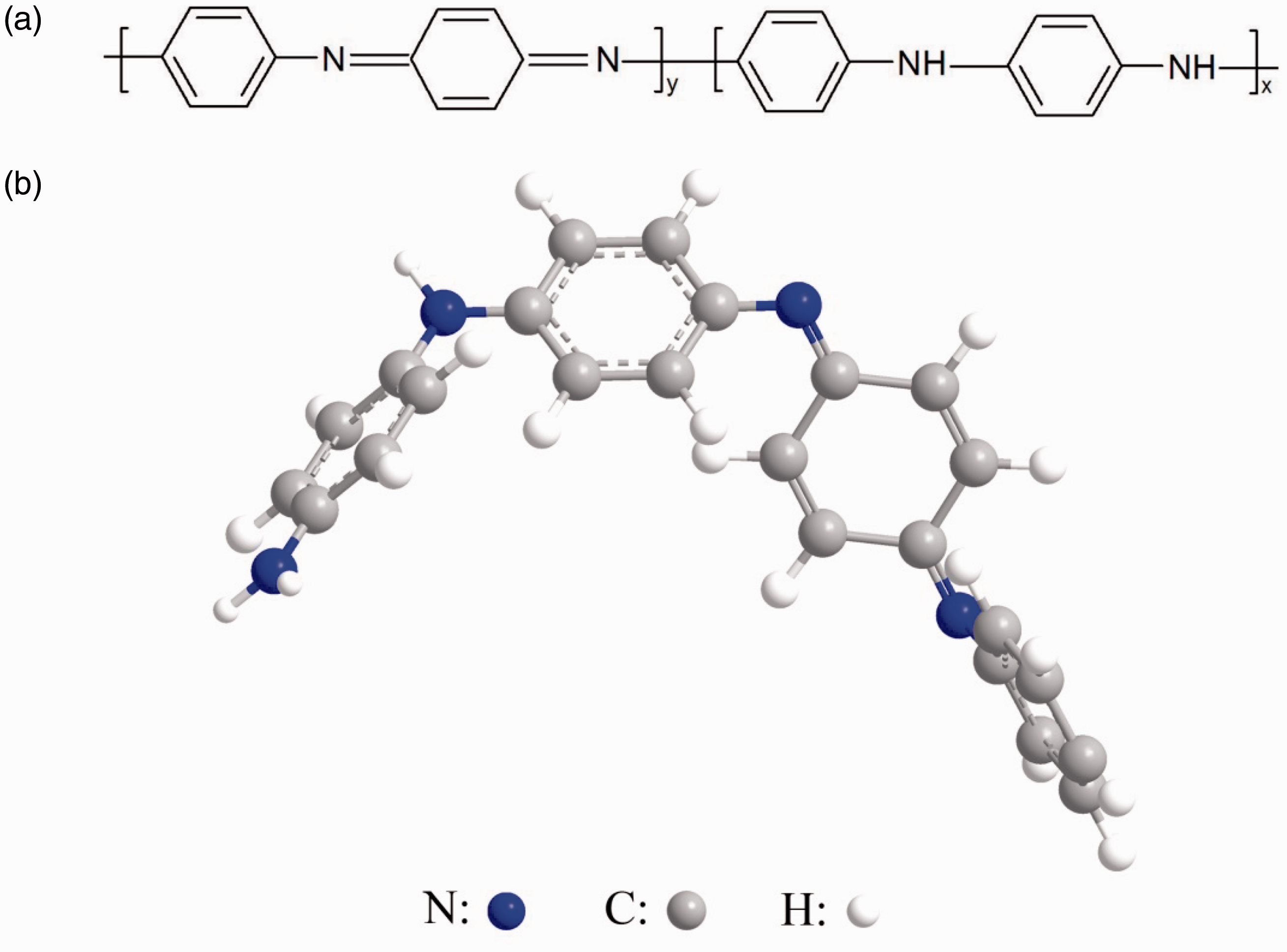
This study presents the preparation of polyaniline/polyvinyl alcohol (PANI/PVA) emulsion and the fabrication of PANI/PVA nanocomposite and electrochromic device, respectively. Four PANI/PVA composites with different PANI concentrations (i.e. 0 wt%, 0.2 wt%, 0.4 wt%, 0.6 wt%) were prepared to investigate the effects of PANI content on electrical and electrochemical properties. Electrochromic properties of the PANI/PVA composite electrospun nanofiber are systematically characterized using a CHI 600D electrochemical workstation (Shanghai Chenhua Instrument Co., Ltd., China). The PANI/PVA composite electrospun nanofiber could be applied in smart textile, sensor, electronic industries and stealth technology. 44
Experimental
Materials and chemicals
Polyvinyl alcohol (PVA, Mw ∼75,000 g/mol, Sigma-Aldrich Co. Ltd., USA), propylene carbonate (PC, C4H6O3, Sinopharm Chemical Reagent Co. Ltd., China) and ethanol (C2H6O, Sinopharm Chemical Reagent Co., Ltd., China) were used as received. Poly (methyl methacrylate) (PMMA, Mw ∼15,000 g/mol) and LiClO4·3H2O salt (purity 96%) were purchased from Sigma-Aldrich. Aniline (AN, C6H7N) was purchased from Sigma-Aldrich. Ammonium persulphate ((NH4)2S2O8, Sinopharm Chemical Reagent Co. Ltd., China) was used as received. Dodecylbenzenesulfonic acid (DBSA) was supplied by Sigma-Aldrich containing a mixture of isomers with a purity greater than 95% and less than 2% sulphuric acid. Indium-tin oxide (ITO) film was supplied by Zhuhai Kaiwei Electronic Components Co.,Ltd., Shenzhen, China. All reagents were used directly without further purification.
Preparation of PANI/PVA solution
The PANI/PVA composites were synthesized by in situ chemical oxidation polymerization of 16 g of dodecylbenzene sulfonic acid (DBSA) and 3.0 g of aniline (AN) monomer in the presence of PVA particle solution. The dodecylbenzene sulfonic acid (DBSA) and aniline (AN) monomer mixture was stirred for 10 minutes and then 50 ml of PVA aqueous solution was added and the mixture was stirred for 30 minutes. By addition of the ammonium sulfate aqueous solution, 3.0 g of (NH4)2S2O8, the mixture was allowed to react for 10 minutes under high-speed stirring at 40℃.
Fabrication of PANI/PVA composite nanofiber
The schematic illustration of the electrospinning machine for PANI/PVA nanocomposites by dynamic electrospinning system used in this study is shown in Figure 2(a). The PANI/PVA solution was extruded from a syringe via a propulsion module through a 2 mm inner diameter plastic pipe to a 2 mm outer diameter plastic pipe inlet to supply solution for the spinning. The extruding speed for the spinning solution was set to be 1.5 ml/h. A high voltage power supply (ES60P-20 W, Gamma High Voltage Research, USA) with an operating voltage ranging from 0 to 50 kV, and 20 kV was applied to the spinneret and the collector in this study. The distance between the needle and the receiver was set to be 16 cm. An ITO conductive film roller receiver with a certain rotating speed was employed to collect the electrospun PANI/PVA nanocomposites. In addition, the ITO conductive film should be transversely straightened in order to guarantee its surface smoothness and the spinneret should be vertical to the rotary roller. Subsequently, the tip of the spinneret was connected to the anode of direct-current (DC) high-voltage power supply, while the collector was connected to the cathode of high-voltage power supply.
(a) electrospinning machine; (b) schematic illustration of the fabrication of PANI/PVA nanocomposites by electrospinning system.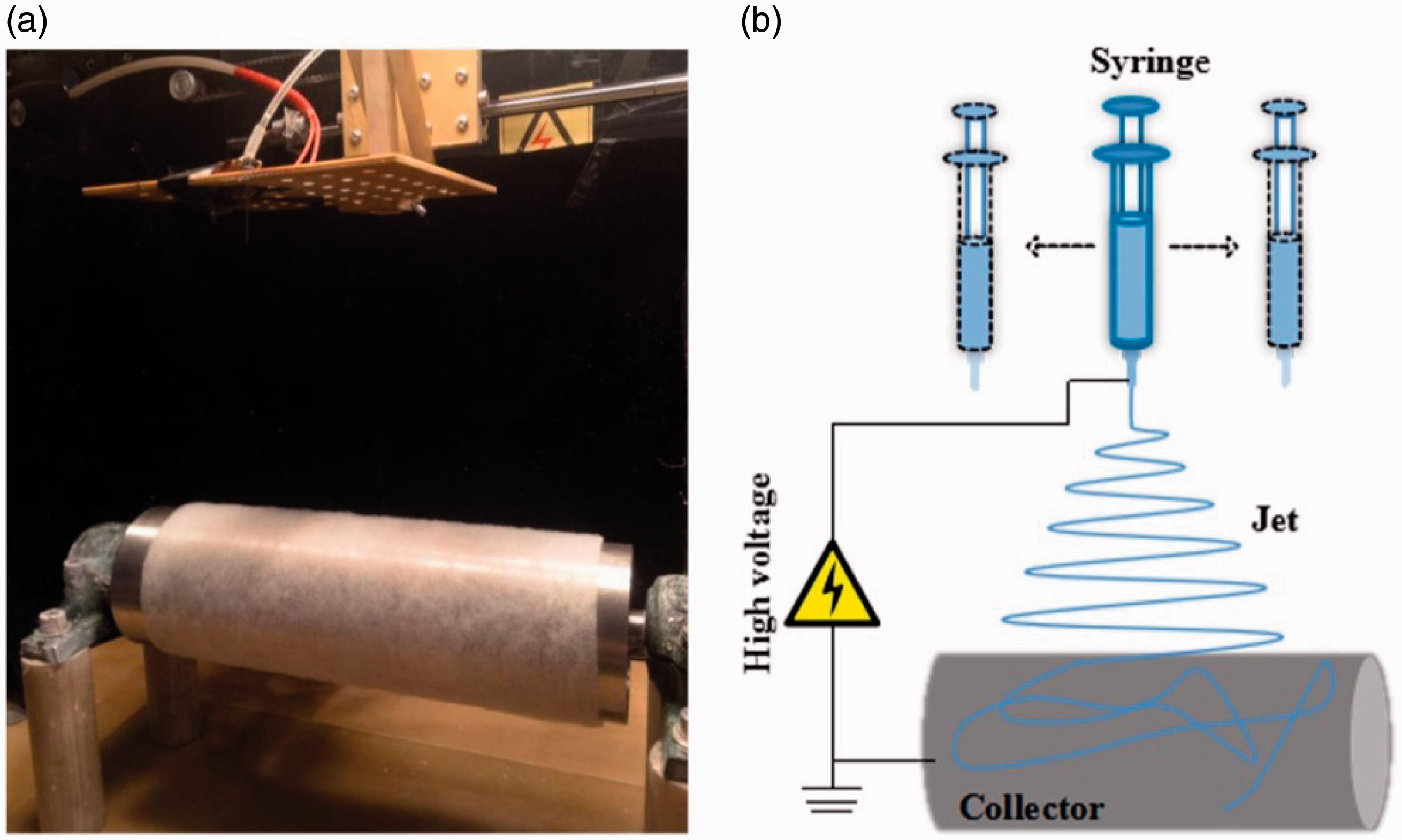
Preparation of electrochromic device
PMMA gel electrolyte was prepared based on the previous research. 45 The LiClO4·3H2O and PMMA were placed in the vacuum drying oven for 24 h at 120℃ and 8℃, respectively. An appropriate amount of dry LiClO4 was fed into the beaker filled with PC solution and then ultrasonic was stirred for 10 minutes to dissolve the LiClO4 completely. After this, the PMMA powders were added into the solution and stirred at 120℃ until the complete dissolution of crystallized-state substance was achieved. Finally, the viscous-state gel solution was prepared, cooled and sealed.
The PMMA gel electrolyte was coated on the PANI/PVA nanofiber membrane directly, and then mutual extrusion between the PANI/PVA-coated ITO film and the PMMA gel electrolyte-coated PANI/PVA film was carried out to remove air bubbles. Subsequently, the electrochromic device (ECD) was prepared after 4 h drying at 60℃ in the vacuum drying oven, as shown in Figure 3. In Figure 3, PMMA gel is designated as gel electrolyte and PANI/PVA nanofiber membrane as electrochromic layer, while working electrode and counter electrode indicate the positive electrodes and negative electrodes, respectively, used for testing the performance of the sample. The ITO conductive film could be selected as the counter electrode.
Basic structure of ECD.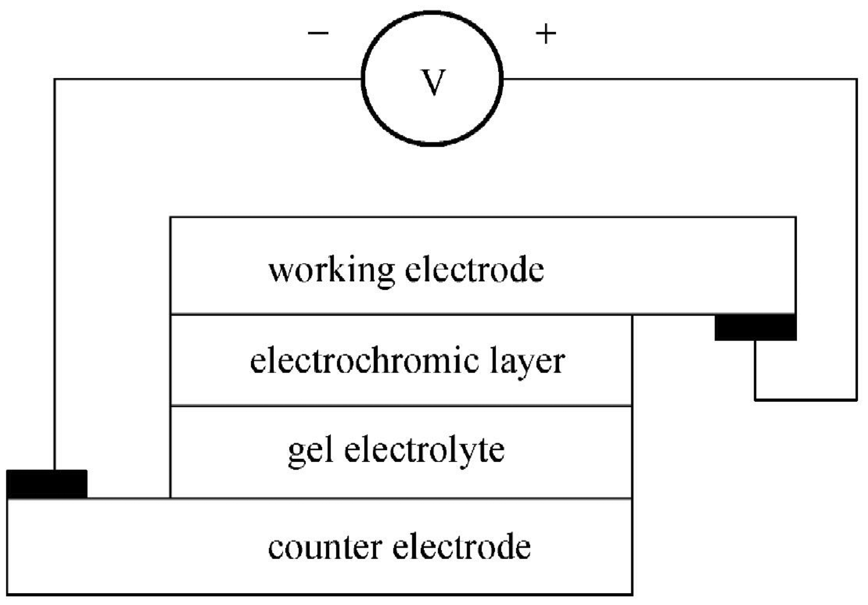
Characterization
Morphology analysis
The morphology of PANI/PVA composites was observed by scanning electron microscope (SEM) (SU8010, Hitachi, Japan) with an accelerated voltage of 15 kV. The surfaces of the samples were coated with a sputter coater (S450, Hitachi, Japan) equipped with a gold target to increase the electrical conductivity of the samples.
Fiber diameter
The fiber diameters typically were measured from images obtained from a SEM by using Image-Pro Plus 6.0 software (Media Cybernetics). Fifty random fibers were selected to measure the fiber diameter; a mean value (average value) with the standard deviation (a measure of variability) of the fiber diameter was reported.
X-ray diffraction analysis
X-ray diffraction (XRD) (k780FirmV-0) was utilized to investigate the effects of electrospinning on the crystallinity of the fiber. JADE 5.0 software (Materials Data, Inc.) was used to calculate the crystallinity of polymer with 0.8 sec/step. In addition, the relationship between the crystallinity and electrospinning parameters was investigated based on the fitting curve.
Determination of emulsion viscosity
The determination of PANI/PVA emulsion viscosity was conducted by the Rotary Viscometer (NDJ-1, Shanghai Precision Science Instrument Co. Ltd.). The sample was tested 5 times in order to calculate the average value of emulsion viscosity.
Mechanical properties
Mechanical properties were characterized by the Electronic Single-fiber Strength Tester (YG006, Shanghai). A long piece of fabric of length 20 mm and width 5 mm was selected as the sample (along the longitudinal direction of the composite nanofiber). Conditioning of each sample was performed in advance; the sample was placed in the constant-temperature laboratory for 24-hour treatment.
Electrochromic properties
Electrochromic properties of PANI/PVA composite were characterized by a CHI 600D electrochemical workstation. The sample was tested for hydrochloric acid solution of 1 mol/L with the electrolyte and scanning voltage within the range of (−0.3) ∼ (+1.4) V.
Results and discussion
Viscosity of spinning solution
The interaction in the molecular chain is characterized by the viscosity of the polymer solution; the curve of emulsion viscosity varying with the amount of PANI, as demonstrated in Figure 4.
Viscosity of emulsion with different PANI amounts.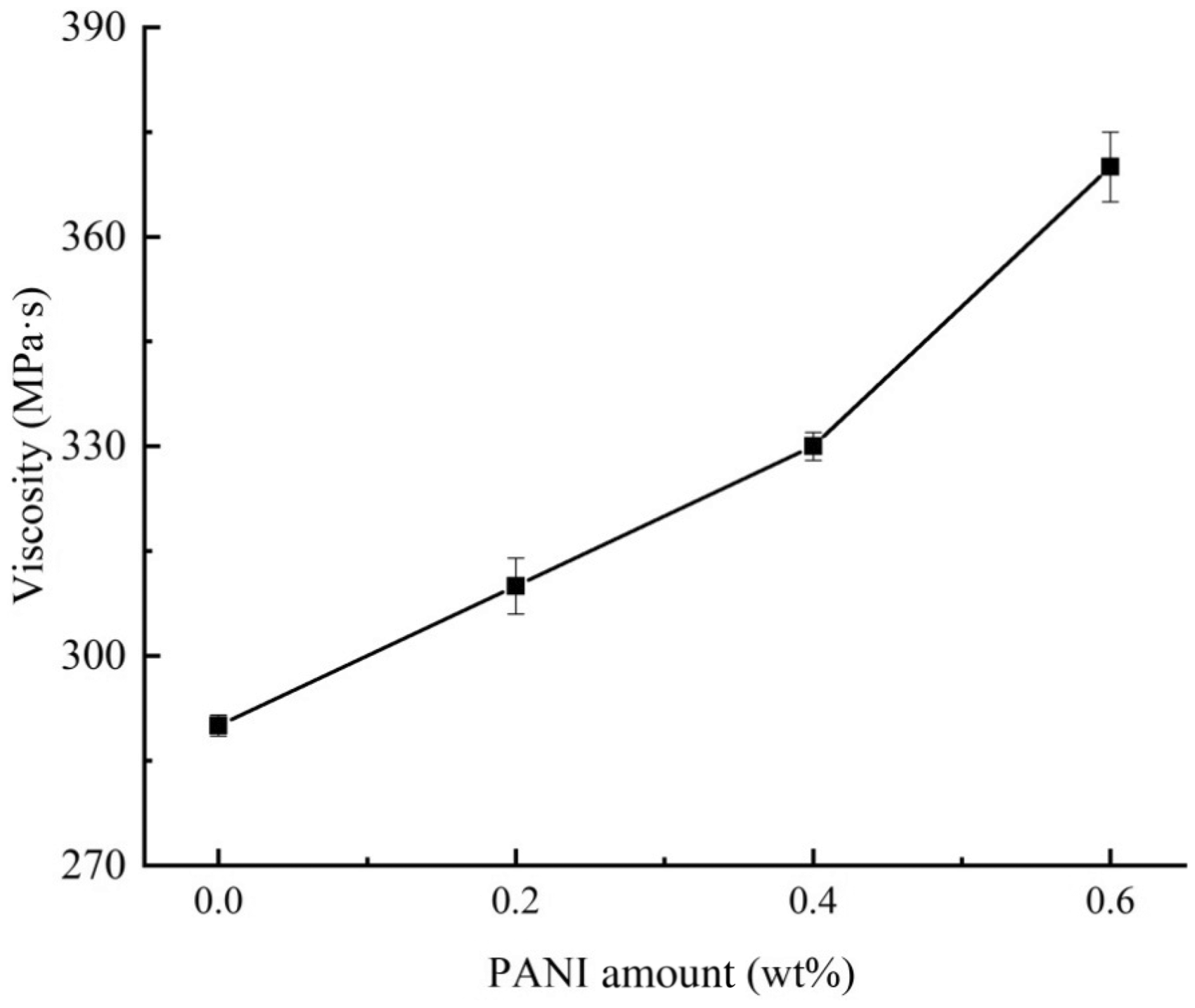
As illustrated in Figure 4, the viscosity of pure PVA emulsion is 290 MPa·s, the emulsion viscosity increases with the increase in the amount of PANI, the result is similar to that of Himanshu et al. 46 The reason is that the PVA molecular chain exhibits excellent flexibility and the entanglement; in addition, strong hydrogen-bonding interaction could be generated between certain -NH- on the PANI macromolecular chain and -OH on the PVA macromolecular chain, improving and optimizing the viscosity of PVA emulsion sufficiently. An excessive increase in the amount of PANI leads to a significant decrease in the viscoelastic properties of the emulsion. The extensional viscosity and relaxation time of emulsion affects the electrospinning process, and the lower spinning solution solubility also affects electrospinning.
Morphology structure
The fiber diameter distribution of electrospun fibers with different amounts of PANI was determined in order to study the effects of PANI amount on the morphology. SEM images and histograms of nanofiber diameter distribution with different amounts of PANI are depicted in Figure 5.
SEM images and fiber diameter distribution of PANI/PVA composites nanofiber with different PANI amounts: (a) 0 wt%, (b) 0.2 wt%, (c) 0.4 wt%, (d) 0.6 wt%.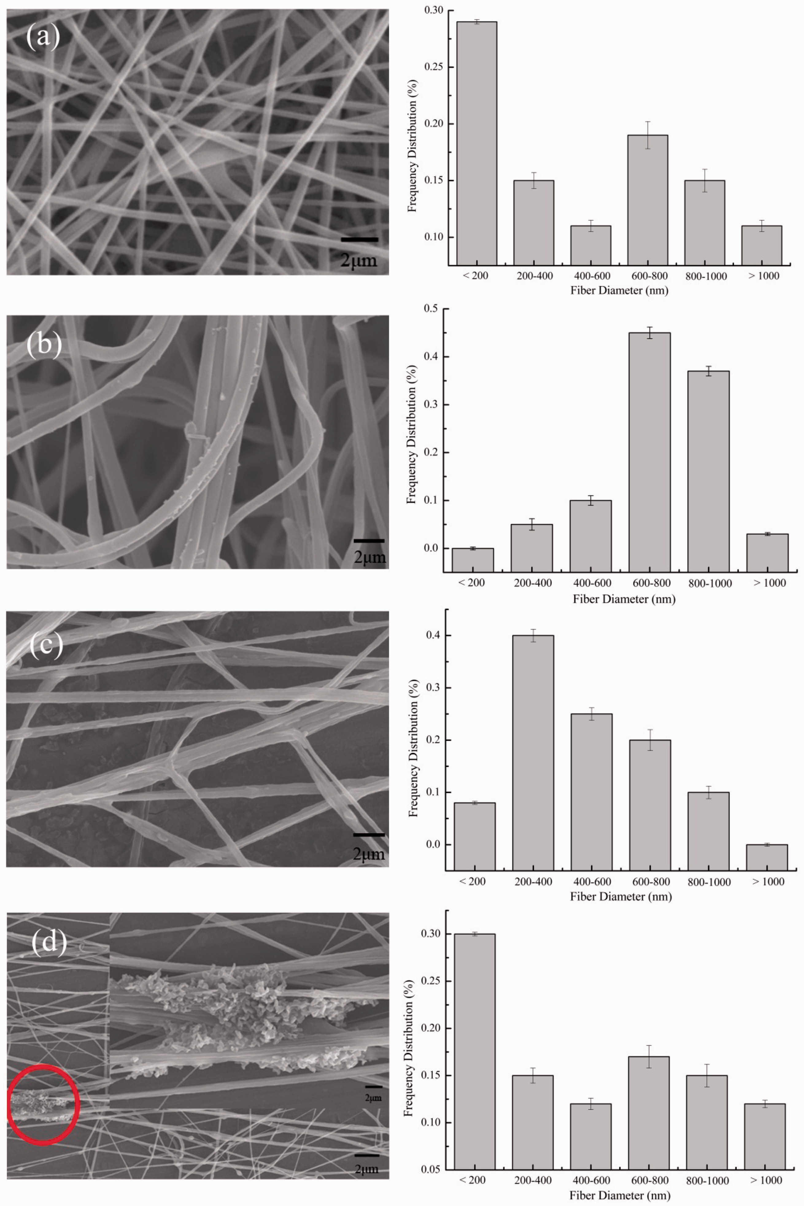
It can be clearly observed in Figure 5 that a sudden steep rise in fiber diameter could be found and the average fiber diameter reaches 730 nm with smooth fiber surface when the PANI amount is 0.2 wt% (Figure 5(b)). The average fiber diameter decreases within the range of 400–550 nm when the fiber surface is rough with the PANI amount increasing from 0.4 wt% to 0.6 wt%.
The above phenomenon may be explained by the following reasons. The load capacity and conductivity of the electrospinning solution increases with the increasing PANI amount and high splitting-degree, high stretch and high whip of jet can also be observed during jet spraying at the tip of the capillary. Considering this, finer fiber diameter could be achieved under the same electrospinning conditions. However, the friction between PANI particle and PVA matrix increases with the increasing PANI amount during fiber stretching, causing resistance during fiber stretching to be generated.47,48 As can be seen in Figure 5(d), agglomeration of PANI particles could be found in the fiber and it is affected by the electrospinning conditions.
Chemical structural analysis
The aggregated-state structure of PANI/PVA composite electrospun nanofiber was characterized by XRD, and it was found that the amount of PANI has effects on the crystallinity of the PANI/PVA composite electrospun nanofiber.
XRD patterns of PANI/PVA composite electrospun nanofiber fabricated with different PANI amounts are illustrated in Figure 6. Four peaks were observed in the PVA with 0 wt% PANI,at 19.4°, 32°, 39.5° and 46.1°. The blunt peak of PVA at about 20° is clearly observable, indicating the presence of PVA. In addition, peaks with a slight difference in intensity can be found at 9.0°and 33.5°, which reveals the presence of PANI.
XRD pattern of PANI/PVA composite electrospun nanofiber fabricated with different amounts of PANI.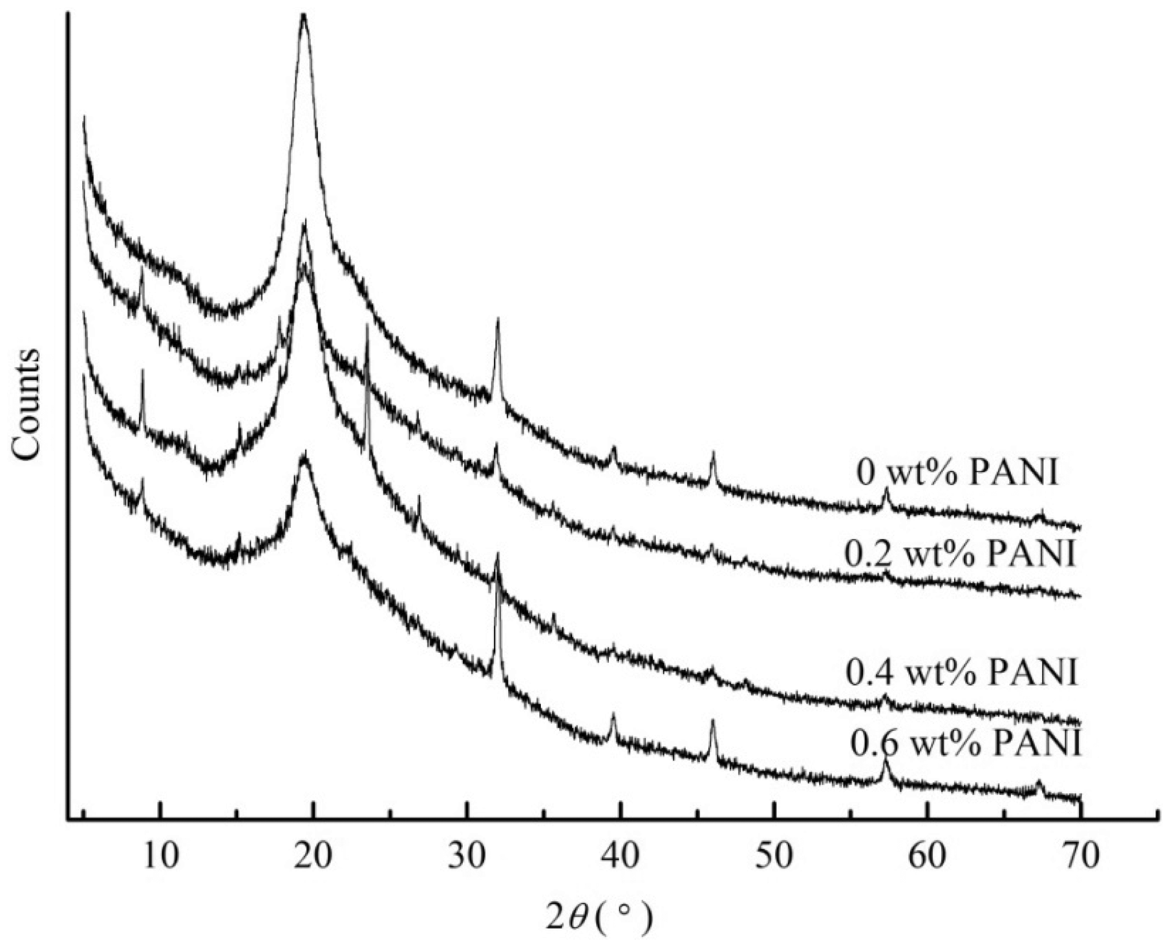
The relationship between PANI amounts and fiber crystallinity is shown in Figure 7; it can be clearly observed that the PANI amount has a great effect on the crystallinity of the PANI/PVA composite electrospun nanofiber. The crystallinity of the PANI/PVA composite increases initially, due to addition of PANI, and then decreases with the amount of PANI further increasing from 0.2 wt% to 0.6 wt%. Therefore, it can be concluded that the addition of PANI contributes to the fabrication of a fiber with excellent morphology, which improves the crystallinity of the composite fiber.
Relationship between PANI amounts and the crystallinity of PANI/PVA fiber.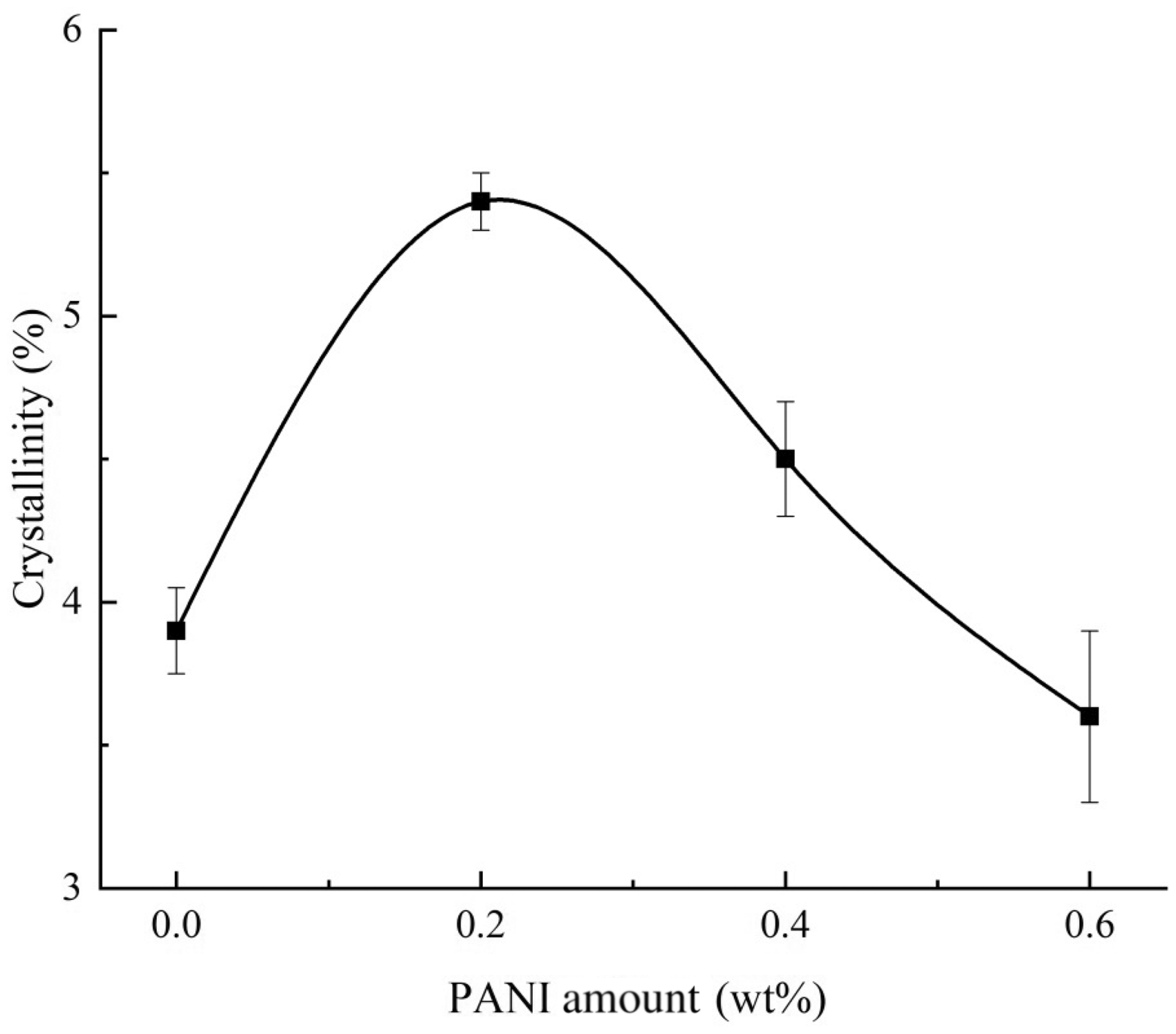
Mechanical properties
The mechanical properties of the PANI/PVA composite electrospun nanofiber mainly depend on the mechanical properties of the fiber, the entanglement state of the fibers and the surface density. The relationship between surface density and the mechanical properties of the electrospun PANI/PVA composite electrospun nanofiber is shown in Figure 8.
Relationship between surface density and mechanical properties of PANI/PVA composite electrospun nanofiber.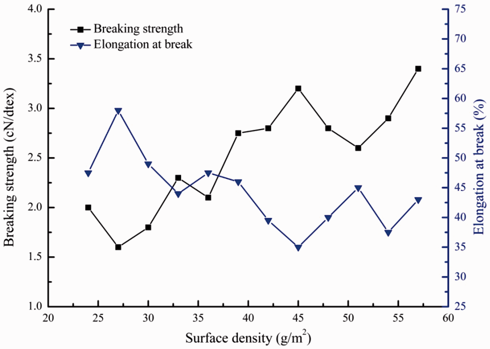
Variance analysis of mechanical properties of PANI/PVA nonwoven fabric with different surface densities
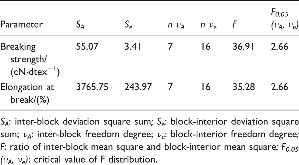
SA: inter-block deviation square sum; Se: block-interior deviation square sum; νA: inter-block freedom degree; νe: block-interior freedom degree; F: ratio of inter-block mean square and block-interior mean square; F0.05 (νA, νe): critical value of F distribution.
Electrochromic behavior of PANI/PVA composite electrospun nanofiber
The electrochromic behavior of PANI/PVA composite electrospun nanofiber was characterized by cyclic voltammetry with scanning speeds of 5 mV/s, 20 mV/s, 50 mV/s and 100 mV/s. Cyclic voltammetry (CV) curves for PANI/PVA composite electrospun nanofibers are illustrated in Figure 9. As can be seen in Figure 9, the current of PANI/PVA composite electrospun nanofiber is 0.9 ∼ 1.0 mA, higher than the 0.8 mA current indicated in the literature;
49
the redox peak of the CV curve of PANI/PVA composite electrospun nanofiber is not apparent and the PANI/PVA composite electrospun nanofiber indicates a color change sequence of yellow, green and blue during the cycle of positive scanning and reverse scanning, with relatively light color intensity. Comparison of the distribution of PANI particles on PVA fiber could be conducted based on the material thickness and alignment.
CV curves of PANI/PVA composite electrospun nanofibers at different scanning rates: (a) 5 mV/s; (b) 20 mV/s; (c) 50 mV/s; (d) 100 mV/s.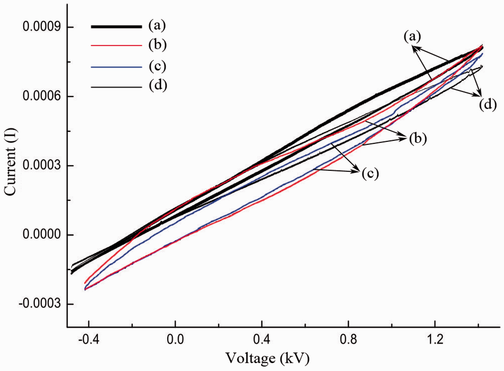
The structure model of distribution of PANI particles on PANI/PVA composite electrospun nanofibers is demonstrated in Figure 10. As can be seen in Figure 10, some distribution modes of PANI particles on PVA fiber could be presented. The models in Figure 10(a), (c) and (e) exhibit superior conductivity compared with other models. The reason is that the compact alignment of PANI particles contributes to the transition of reaction force between particles under the low reaction force resulting in charge transfer, which could be proved by electrochromic behavior. Similarly, the model of compact and dislocated type in Figure 10(d) presents better electrochromic behavior than the model of dispersed type in Figure 10(b); the model of dispersed and heteromeral displacement in Figure 10(h) provides better electrochromic behavior than models in Figure 10(f) and (g). The reason is that different distances between PANI particles has great influence on electrochromic behavior. Furthermore, the thickness and alignment of the composite fiber are also considered as the principle factors of electrochromic properties.
Structure models of PANI/PVA composite electrospun nanofibers. (a) Compact type, (b) Dispersed type, (c) Compact and dislocated type, (d) Dispersed and dislocated type, (e) Compact and homolateral type, (f) Dispersed and homolateral type, (g) Dispersed and heteromeral type, (h) Dispersed and heteromeral displacement type.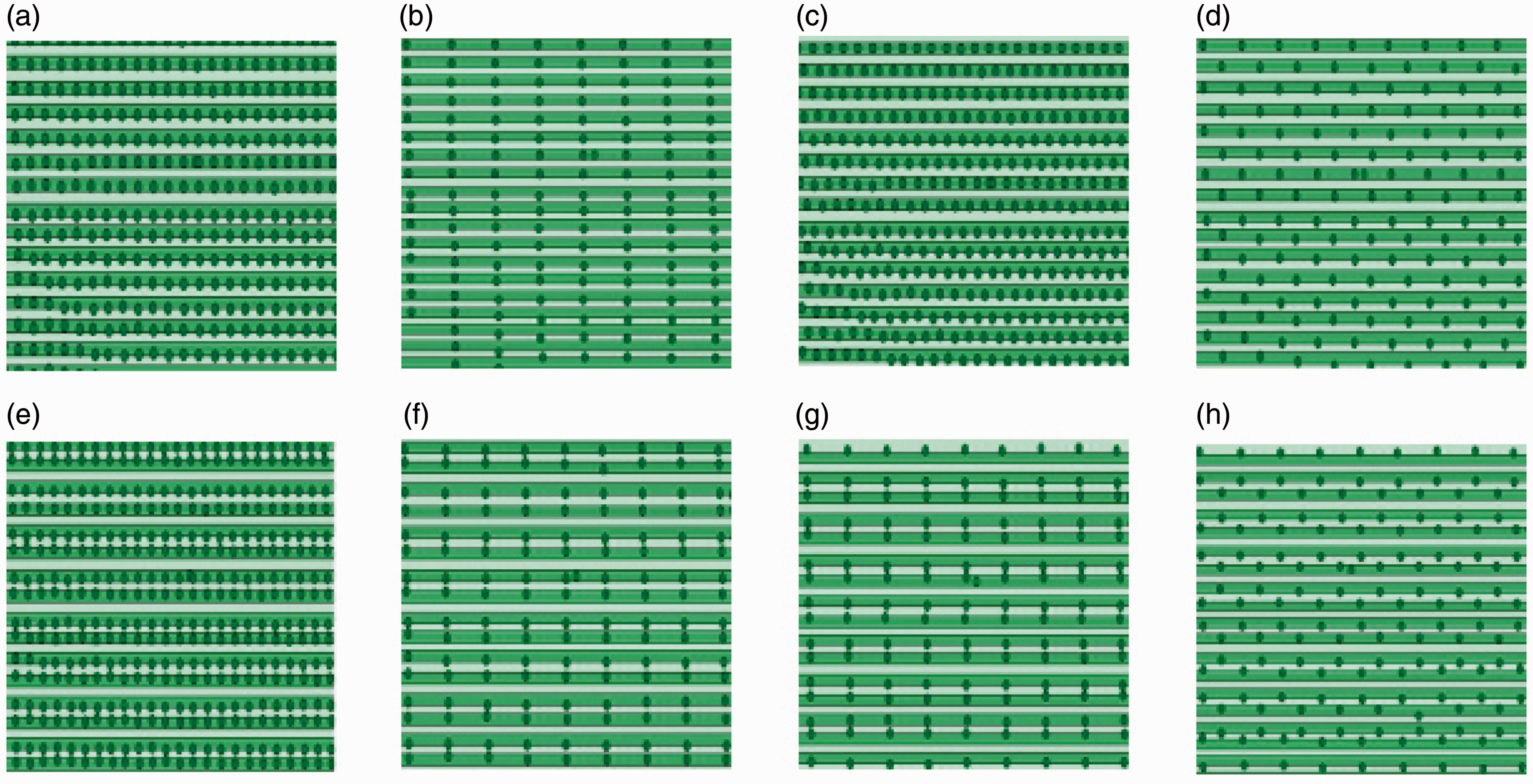
The electrochromic behavior of ITO-plated conductive composite nanofiber membrane with the voltage range of (−1.5) ∼ (+1.5) V is demonstrated in Figure 11. The color of fabric changes from dark green into black, and then changes to golden yellow under an increasing voltage. The electrochromic behavior of the conductive composite nanofiber membrane is actually based on the electrochromism of PANI, and the ITO-plated conductive composite nanofiber membrane provides the PANI with ion for its oxidation-reduction reaction and achieves internal ion conduction rather than electrochromism.
ECD images of PANI/PVA composite electrospun nanofibers with ITO plate. (a) Dark green, (b) Black, (c) Golden yellow.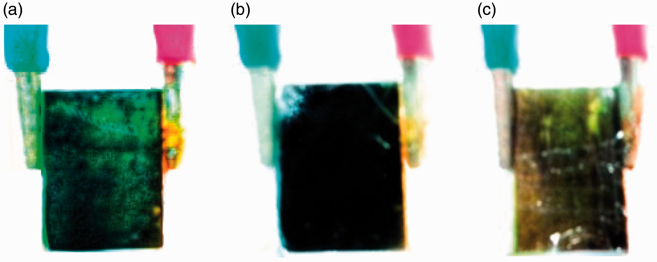
The electrochromic behaviors of the prepared electrochromic device with applied voltage of (−1.5)-(+1.5) V are depicted in Figure 12. The electrochromic layer is made of composite nanofiber membrane at nano-scale and the color depth of the composite nanofiber membrane is light. For this reason, the light yellow of the electrochromic layer failed to be recorded; however, it could be conjectured that the sequence of electrochromic behavior of PANI/PVA composite electrospun nanofiber membrane is light green, light blue and light yellow as the voltage increases, based on the existing color change.
Color chart of symmetric ECD of composite electrospun nanofibers.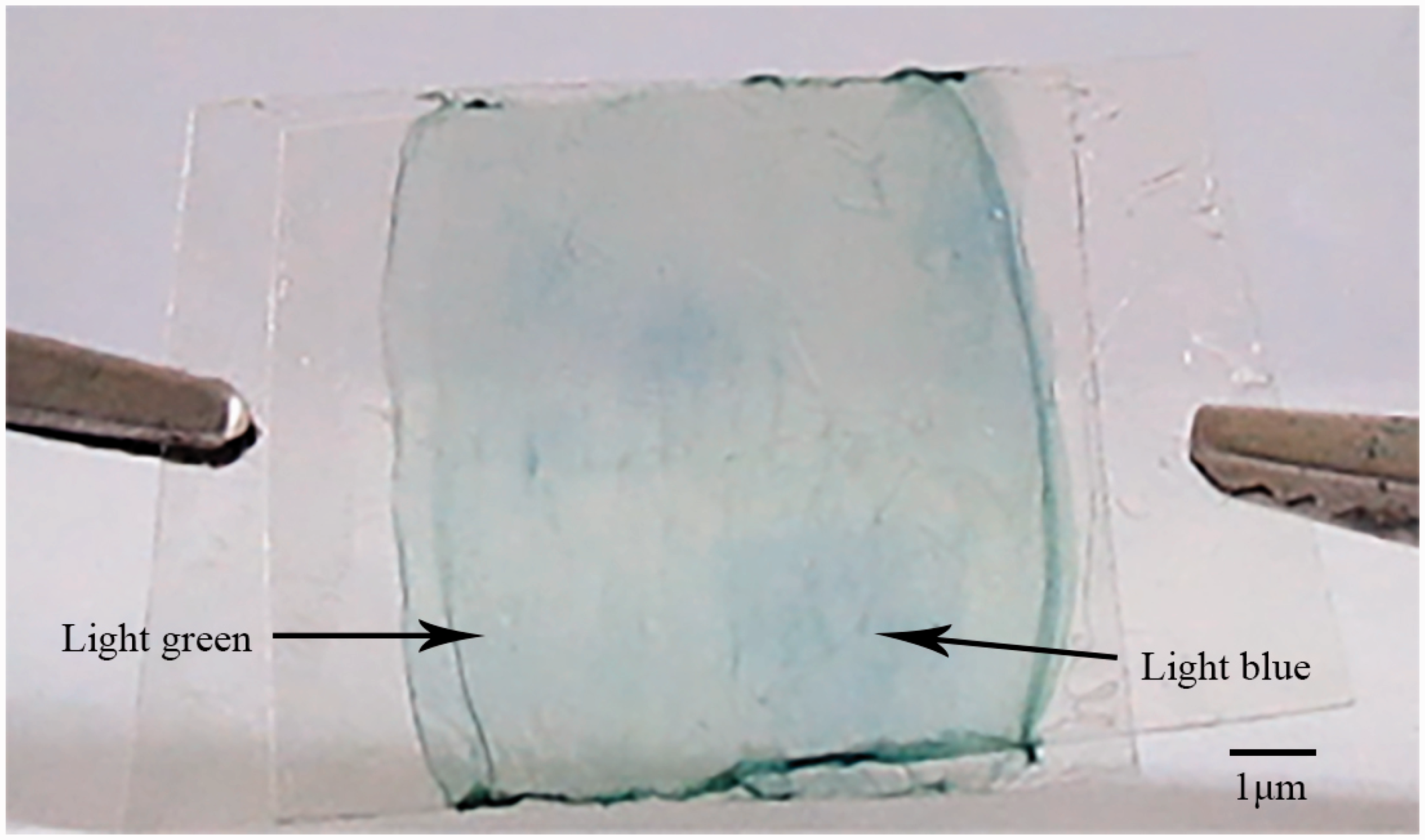
Conclusions
The experiment indicates that PANI/PVA composite electrospun nanofibers present electrochromic behavior with a color change sequence of green, blue and yellow. Cyclic voltammetry was conducted to determine the electrochemical behavior of the PANI/PVA composite electrospun nanofiber membrane at scanning speeds of 5 mV/s, 20 mV/s, 50 mV/s and 100 mV/s, and it was found that the CV curves present similar trends and the redox peaks are almost indiscernible. It was found that electrochromic behavior is linked to the distance between the PANI particles and the directionality of the fiber, based on the establishment of a model used for indicating the distribution of PANI particles in the PVA fiber.
Footnotes
Declaration of conflicting interests
The authors declared no potential conflicts of interest with respect to the research, authorship, and/or publication of this article.
Funding
The authors received no financial support for the research, authorship, and/or publication of this article.