
Abstract
Aiming at achieving online monitoring of the yarn formation process of vortex spinning, this paper presents a direct observation method that adopts a charge-coupled device camera fitted with an industrial endoscope that can reach into the nozzle chamber through a small hole drilled on the nozzle wall. Local pressure distortion in the vortex chamber due to the mounting of the observation apparatus was found experimentally. However, the yarn quality was not significantly affected, indicating that the proposed method has the potential to find industrial applications. Based on this method, the formation process of core-spun yarn containing a copper wire manufactured on a modified vortex spinning system is successfully observed. The results show that the core wire is covered by the main strand (core fibers), while the main strand is false-twisted during the yarn formation process. The level of false twist in the main strand fluctuates with time. The level of false twist in the main strand is higher in the upstream region, while it gradually decreases toward the downstream. Mostly, the trailing ends of some fibers are separated from the main strand and expand over the spindle tip to wrap around both the core fibers and core wire to form wrapper fibers in the yarn, while the leading ends of a smaller number of fibers are separated to form wrapper-wild fibers in the yarn. The proposed method can be extended to the study of fiber movement in confined spaces in other textile manufacturing processes.
Vortex spinning, which utilizes a high-speed swirling airflow to insert twist into the yarn, is one of the recent advancements in yarn manufacturing technologies. Due to the fasciated structure of the vortex spun yarn, that is, the yarn consists of twistless fibers in the core and helical fibers wrapping the core, vortex spinning technology is an excellent candidate for producing core-spun yarns. Ortlek and Ulku 1 reported the manufacturing of core-spun yarns containing spandex on a Murata vortex spinner and investigated the effects of spandex and yarn counts on the yarn properties. Ortlek 2 also reported an investigation on the influence of some process variables on the mechanical properties of vortex core-spun yarn containing elastane. Pei et al. 3 recently reported a modified vortex spinning system for manufacturing core-spun yarns. The most significant modification of this system compared to the traditional vortex spinning system lies in the introduction of a circumferential slot on the top front roller and a filament feeding orifice (FFO) through the fiber guiding element for delivering the core filament into the nozzle.3,4 Scanning electron microscopy (SEM) observation reveals that the core filament is embedded in the twistless core fibers, which are tightly bound by the helical wrapper fibers. 3 However, the formation principle of core-spun yarn produced on the modified vortex spinning system is still unclear and therefore needs to be revealed for predicting and optimizing the structure and properties of the yarn.
The yarn formation principle of vortex spinning has been of great interest to researchers in the field of spun-yarn technology since the launch of the first Murata vortex spinner in 1997. The manufacturer of the Murata vortex spinner has provided a viewpoint of the ‘semi-open-end’ yarn formation principle in that the trailing ends of the fibers expand due to the whirling force of the airflow and then twine over the spindle to whirl around the core of the fiber strand as they are drawn into the spindle.5,6 However, no experimental images have been provided to support this claim. Some researchers followed to investigate the yarn formation principle of vortex spinning via numerical simulation of the airflow characteristics in the nozzle.7–11 Numerical simulation then became a useful tool by proposing flexible fiber models and modeling the dynamic behavior of the flexible fibers in the flow field inside the nozzle based on which yarn formation principle of vortex spinning was studied.12–17 However, numerical simulation not only simplifies the physical properties of the fibers, but also approximates the boundary conditions of the flow field, and thus presents theoretical results that lack reliability. In comparison, due to the tight and confined space in the nozzle with a complex structure, there are great challenges to experimentally study the dynamic behavior of the fibers in the yarn formation process of vortex spinning. The only experimental study was reported by Pei et al., 18 who investigated the fiber motion in a magnified, transparent nozzle made from Plexiglas according to Reynolds number singularity via high-speed photography. The limitation of their study is that only one single fiber, which was represented by a yarn, was adopted in the experiment. Therefore, it is obviously impractical for this method to be applied in industrial production. Furthermore, there has been a lack of both numerical and experimental studies on the formation process of vortex core-spun yarns to date.
In view of the above, this research provides a direct observation method for experimentally investigating the yarn formation process of vortex spinning. This method employs a charge-coupled device (CCD) camera fitted with an industrial endoscope that reaches into the nozzle chamber through a small hole on the nozzle wall to capture the images of yarn formation, which have not been reported before. Based on the experimental images of the fiber movements, formation of the core-spun yarn manufactured on the modified vortex spinning system 3 is investigated and analyzed. The method reported here can be extended to the experimental study of the yarn formation process of traditional vortex spinning. This paper is aimed at providing a potential means of online monitoring the yarn formation process and yarn structure, optimizing the process and nozzle parameters, and even automatically controlling the yarn quality on a vortex spinning machine. This research is also expected to provide a method of studying the dynamic behavior of fibers in confined spaces during textile manufacturing processes.
Experimental details
Materials
Viscose rayon fibers (Shandong Shenghe Textile Co., Ltd, China) that have a mean length of 38 mm and a fineness of 1.5 dtex were adopted as the staple fibers for the vortex core-spun yarns. They were converted into roving with a linear density of 680 tex. An ultrafine enameled copper wire (Jiangshan Hengchang Electric Wire Co., Ltd, China), which is coated with a polyurethane film of a thickness of about 5 µm and has a core diameter of 50 µm, was employed as the core filament of the vortex core-spun yarn. Figures 1(a) and (b) show images of the ultrafine enameled copper wire.
The ultrafine enameled copper wire: (a) wire wound on a bobbin; (b) scanning electron microscopy image of the wire.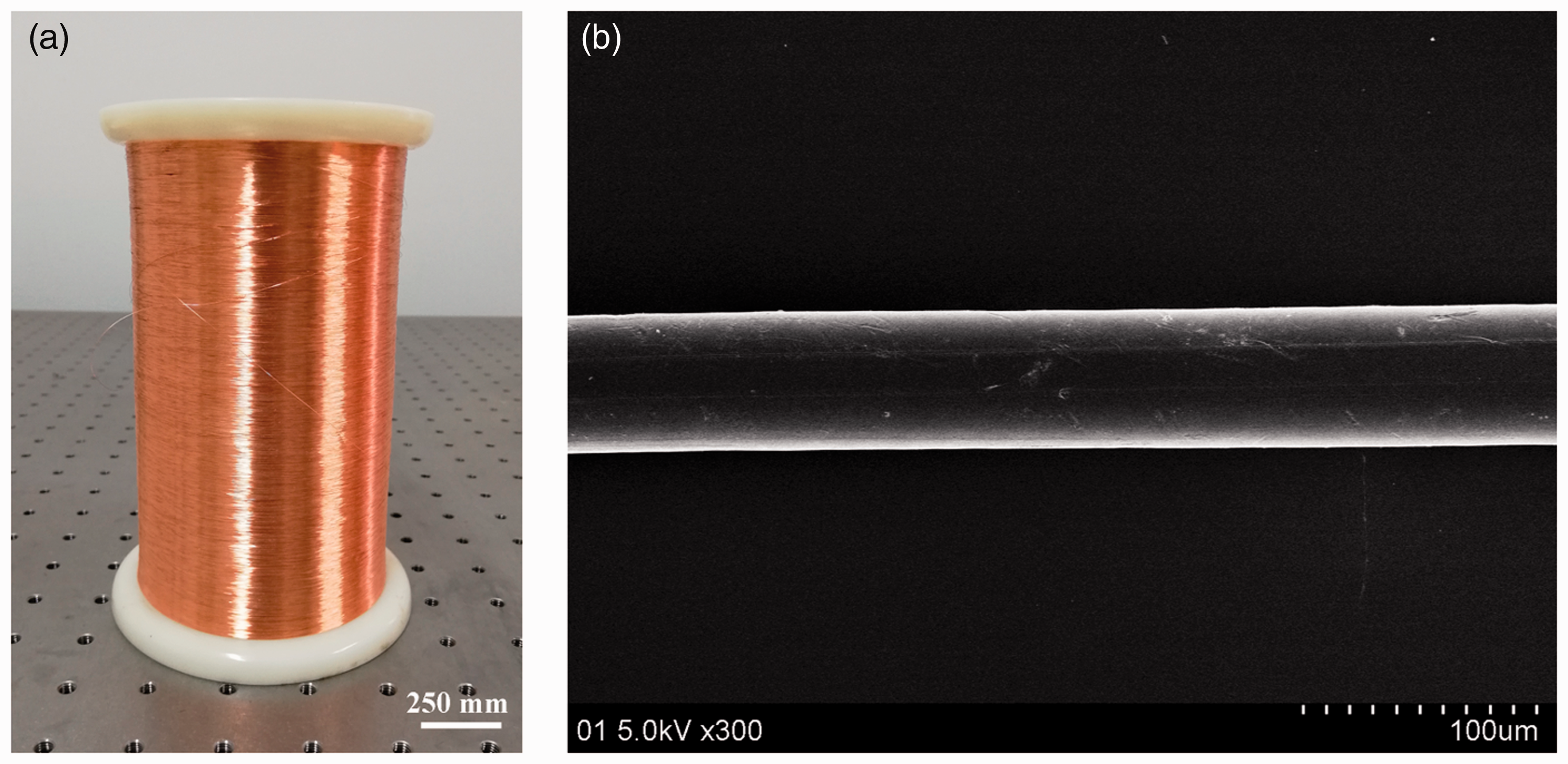
Experimental arrangement for observing the yarn formation process
Figures 2(a) and (b) show schematic diagrams of the experimental arrangement for observing the yarn formation process of the modified vortex spinning for producing core-spun yarns. The observation apparatus consists of a CCD camera, two light sources, a light source controller, a transmission line, a laptop, and an industrial rigid endoscope and its optical interface. The industrial endoscope (Model FIP2.7-100, Shanghai Aohua Endoscopy Co., Ltd, China), which transmits images of the yarn formation process out of the nozzle chamber, is composed of the working pipe, the main body, the eyepiece-connecting pipe, and the eyepiece cover. The working pipe, which is fitted with a line of lenses and an objective internally, has an outer diameter (OD) of 2.7 mm and a viewing angle of 0°. The eyepiece is enclosed in the eyepiece cover, the back portion of which is connected to the optical interface. The back portion of the optical interface is connected to the CCD camera, which captures the images. The CCD camera (Model DFK 23G274, The Imaging Source Asia Co., Ltd, Taiwan) has a resolution of 1600 × 1200, a pixel size of 4.4 µm × 4.4 µm, a maximum frame rate of 20 fps, and a minimum exposure time of 1/40,000 s. Clear images can be obtained by the CCD camera by adjusting the focusing ring on the optical interface. The transmission line connects the CCD camera with the laptop (Model T430, Lenovo Group Ltd, China), which is used for the storage and processing of the captured images. Two ultrahigh-brightness light-emitting diodes (LEDs) with a rated power of 10 W and a rated current of 3 A are adopted as the light sources. The LEDs are placed behind a set of lenses for diverging the rays to cover a larger area in the nozzle chamber. The LEDs and the lenses in front of them are encapsulated into a tubular housing whose front end is of a smaller OD (3 mm) than its back end. The intensity of the light sources can be adjusted by a controller to fit for different exposure times of the CCD camera. Two holes (H1 and H2) are drilled through the wall of the vortex tube for introducing the light sources and one (H3) is drilled for the endoscope. The inner diameters (IDs) of hole H1 and hole H2 are equal to the OD of the small end of the light source housing, while the ID of hole H3 is equal to the OD of the working pipe of the endoscope. The axes of the three holes are all along the radial direction of the vortex tube and are in the same plane perpendicular to the axis of the vortex tube. This plane is 5 mm beneath the injector exits. The angle between the axes of hole H1 and hole H3 is 65°, while the angle between hole H2 and hole H3 is 40°. The angles between the endoscope and light sources have been optimized through trial and error to prevent backlighting and to provide a large area illuminated by the light. The working pipe of the endoscope is inserted into hole H3 with its front end surface flush with the internal wall of the vortex tube. The two small-diameter ends of the light source housings are inserted into hole H1 and hole H2, respectively. The front end surface of the frontmost lens for the light source is of a concave shape conforming to and flush with the internal wall of the vortex tube.
Experimental arrangement and apparatus for observing the yarn formation process: (a) cross-sectional view along B–B; (b) partial longitudinal view along A–A; (c) nozzle; (d) charge-coupled device (CCD) camera fitted with an industrial endoscope. FFO: filament feeding orifice.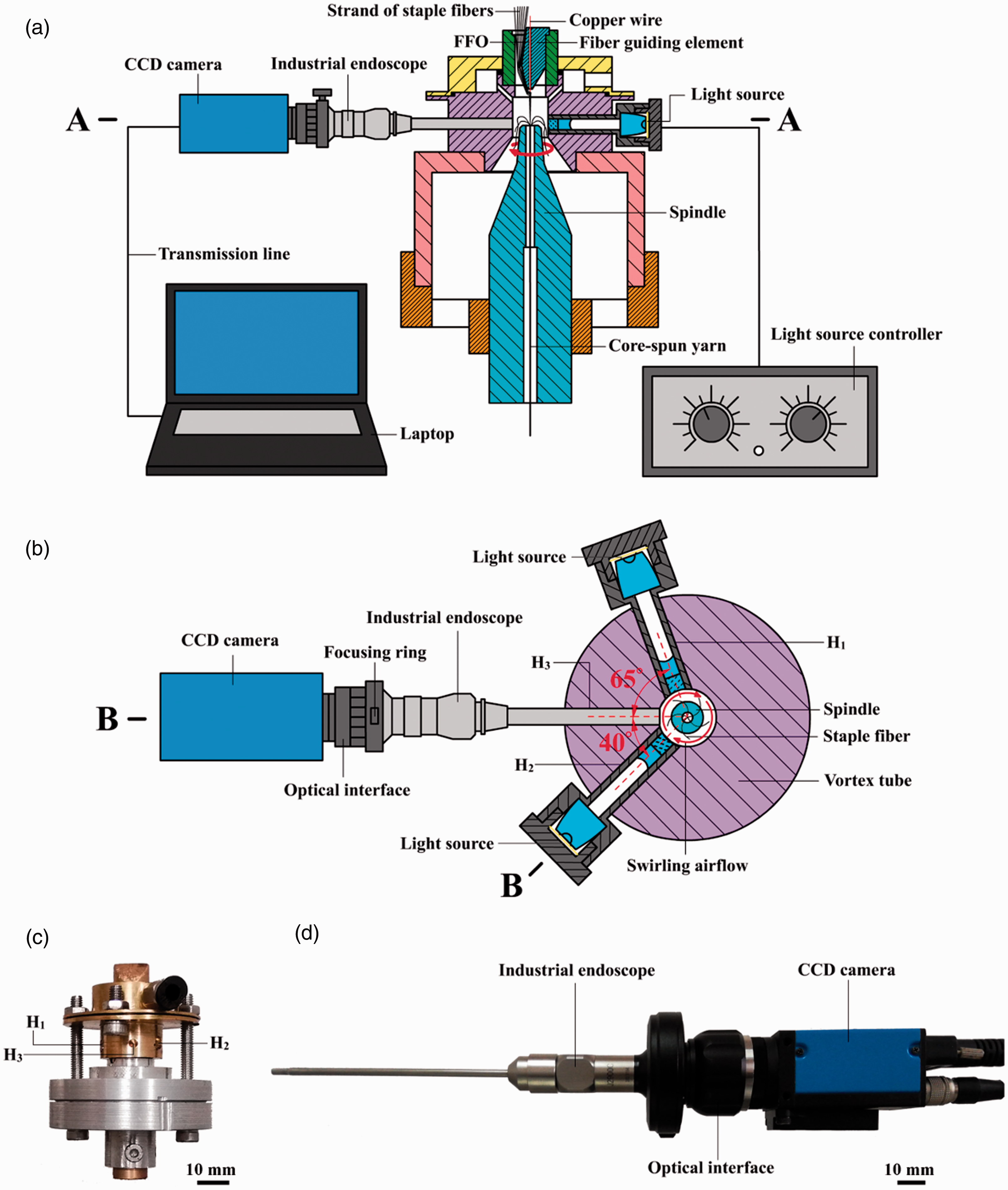
To evaluate the influence of the employment of the observation apparatus on the flow field inside the nozzle, the air pressure in the vortex chamber (the cavity inside the vortex tube) of the nozzles with and without the observation apparatus was measured using a Pitot tube. The measured air pressure values of the two nozzles were then compared. As shown in Figure 3(a), the Pitot tube used had an OD of 4 mm and a conical nose. As shown in Figure 2(a), since the gap between the spindle and the vortex chamber wall is quite small, it was impossible to insert the Pitot tube into the vortex chamber with the spindle installed on the nozzle. Therefore, the spindle was uninstalled when measuring the air pressure inside the vortex chamber. Since the shape of the conical nose of the Pitot tube was very similar to the conical tip of the spindle, it was reasonable to insert the Pitot tube coaxially into the vortex chamber so that the air pressure along the axis of the vortex tube was measured. Besides, since the velocity of the airflow in the vicinity of the wall was very high, the Pitot tube vibrated intensively when it was placed close to the wall, leading to great fluctuations in the measured values. This was another reason for measuring the air pressure along the axis of the vortex tube. The outlet of the inner tube of the Pitot tube was connected to a digital pressure gauge (Model AS510, Smart Sensor®) with a resolution of 1 Pa using a silicone tubing with a length of 300 mm. Air pressures at different axial positions were measured. The measurement position started at the plane where the injector exits are located and ended at the plane 3 mm downstream of the vortex tube outlet, moving from upstream to downstream with an increment of 1 mm. The Pitot tube was fixed onto a three-axis positioning system to facilitate precise adjustment of its position. In order to obtain reliable results, the same vortex tube was used in the comparative test: firstly, the observation apparatus was mounted onto the vortex tube and measurement of the air pressure was carried out; then measurement was carried out on the same vortex tube with the observation apparatus unmounted and holes H1, H2 and H3 being blocked and sealed with poly(methyl methacrylate) (PMMA). The inner surfaces of the PMMA blocks were milled to concave shapes that conform to and were flush with the internal wall of the vortex tube. The three-axis positioning system and the vortex tube were fixed on a breadboard. The experimental rig is shown in Figures 3(b) and (c). A nozzle pressure of 5.5 × 10⁵ Pa was used in the test.
Experimental rig for measuring the air pressure in the vortex tube with the observation apparatus: (a) the spindle and Pitot tube; (b) and (c) the experimental rig viewed from different sides.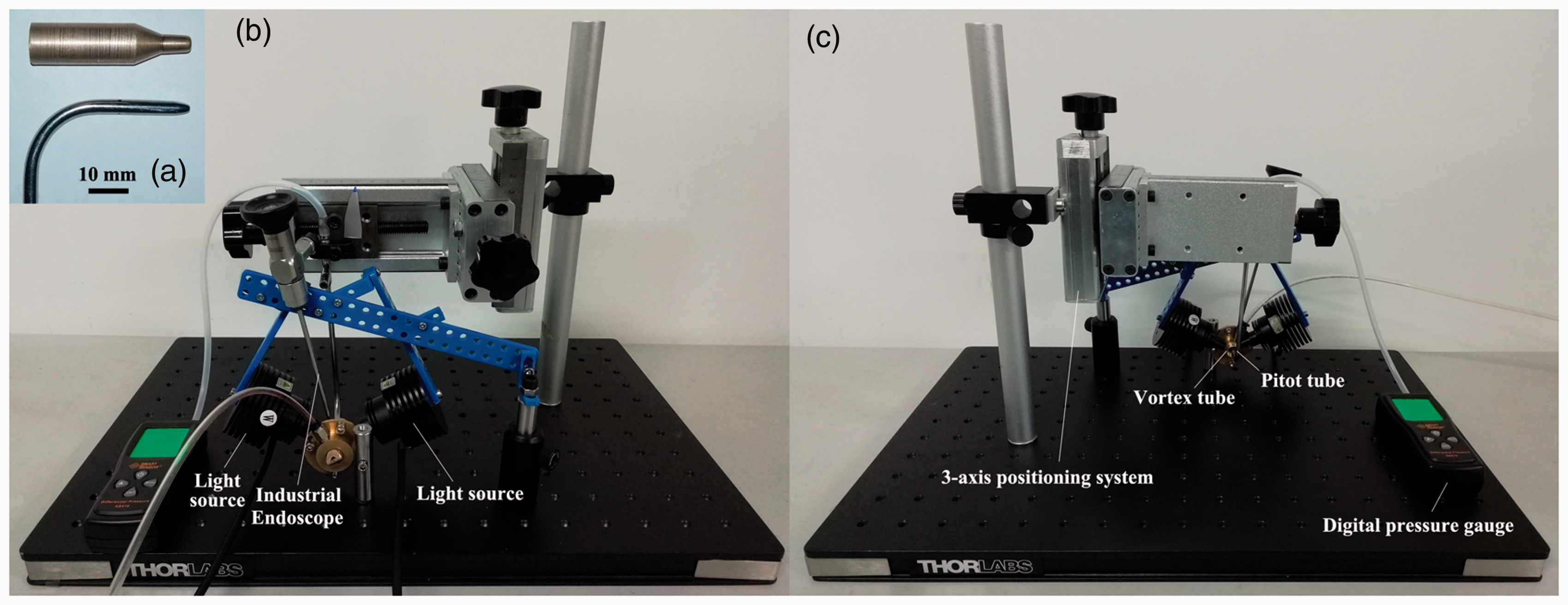
Spinning experiment and observation of the yarn formation process
Core-spun yarns containing a copper wire were manufactured on a modified vortex spintester
19
(Model DHU-P02, Donghua University, China). During the manufacturing process, the copper wire enters the nozzle after being delivered successively by a filament feeding device, a slot on the surface of the top front roller, and the FFO through the fiber guiding element.
3
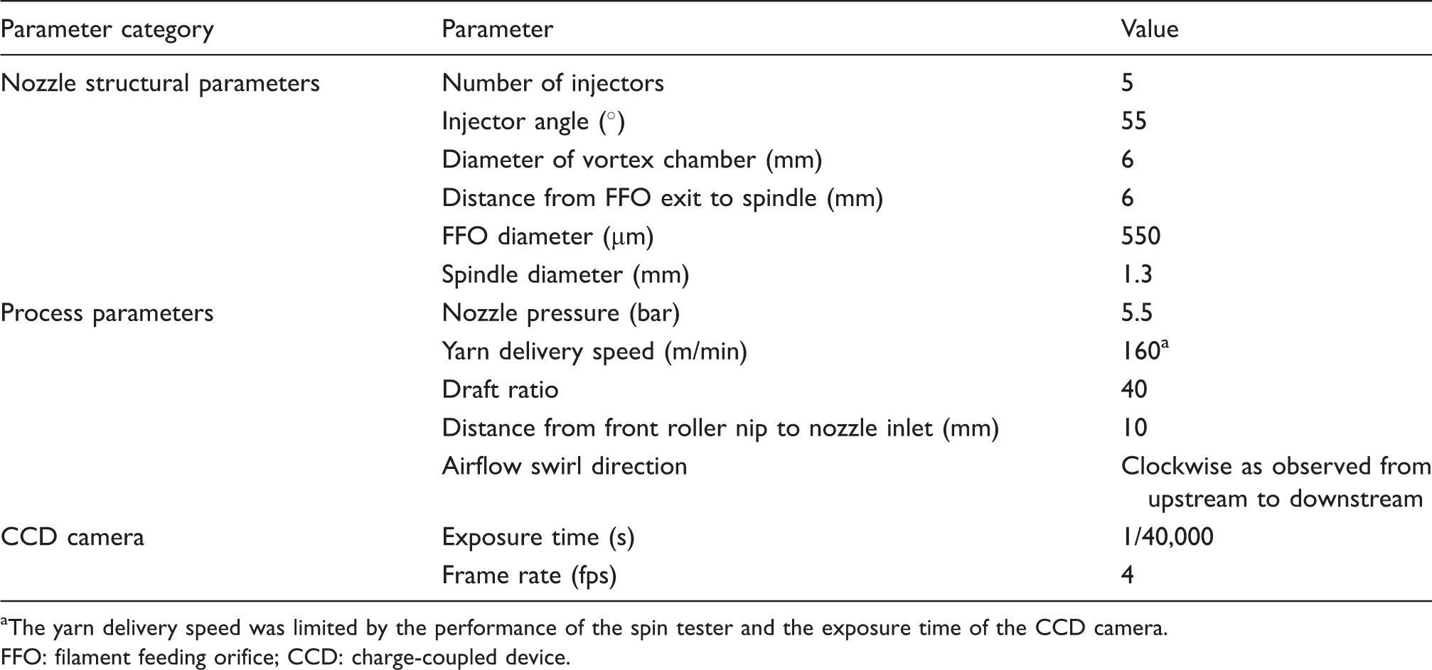
In the meantime, the strand of staple fibers issuing from the front roller nip is sucked into the nozzle to converge with the copper wire. A high-speed swirling airflow is generated inside the vortex chamber after the ejection of air currents from a plurality of tangential injectors. With the force of the swirling flow, the core-spun yarn is formed and the formation process is monitored by the observation apparatus before the resultant yarn is delivered out of the nozzle through the spindle. The main parameters for the nozzle structure, spinning process, and observation adopted in the experiment are listed in Table 1. Figure 4 shows an image of the observation process during yarn manufacturing. In order to evaluate the influence of the employment of the observation apparatus on the spinning process, the quality in terms of tenacity, elongation at break, evenness, and hairiness of the yarns spun using the nozzle with the observation apparatus (N1) and the nozzle without the observation apparatus (N2) were measured and compared. Yarn tenacity and elongation at break were measured according to ASTM standard D2256. Yarn evenness was tested according to ASTM standard D6612. Yarn hairiness was measured according to ASTM standard D5647. A one-way analysis of variance (ANOVA) was used to investigate the effect of the observation apparatus on the yarn quality. The results were analyzed statistically at a 95% level of confidence for significance in differences using Minitab® software version 17.
Observation process during yarn manufacturing. CCD: charge-coupled device. Main parameters for the nozzle structure, spinning process, and observation The yarn delivery speed was limited by the performance of the spin tester and the exposure time of the CCD camera. FFO: filament feeding orifice; CCD: charge-coupled device.
Results and discussion
Influence of the observation apparatus on the spinning process
The testing results of the quality of the yarns spun using the two nozzles of N1 and N2 are shown in Figure 5 and Table 2. A slight decrease of the yarn tenacity and evenness were found for N2 compared to N1, that is, the yarn tenacity decreased by 1.16% and the CVm% increased by 8.79%. As for the elongation at break, an increase of 2.89% was observed for the yarn spun using N2 compared to its counterpart without observation apparatus. For the yarn hairiness, an obvious increase of the average number of hairs no longer than 3 mm can be seen for the yarn produced by N2 compared to that of N1. The difference in the numbers of yarn hairs longer than 3 mm is not so obvious for the two nozzles, with the number of hairs of 8 and 9 mm of the yarn spun by N2 being even slightly lower compared to N1. The slight deterioration of the quality, that is, tenacity, evenness, and number of hairs no longer than 3 mm, of the yarn spun using N2 may be attributed to the disturbance in the local flow field caused by the difference of the radius of curvature of the end surface of the endoscope from the radius of curvature of the vortex chamber wall. However, statistical analysis has shown that the influence of mounting the observation apparatus on all the yarn quality indicators above is not significant at the 95% level of confidence.
Comparison of the tenacity, elongation at break, and evenness of the yarns produced using the nozzles with and without observation apparatus. Comparison of the hairiness of the yarns produced using the nozzles with and without observation apparatus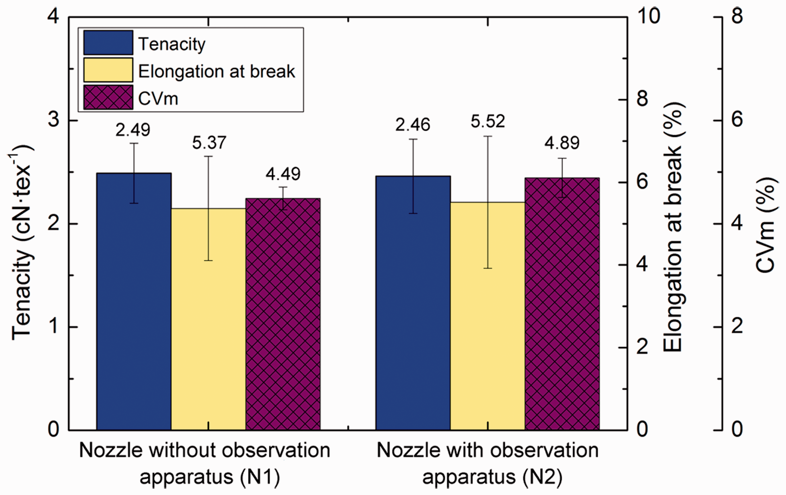
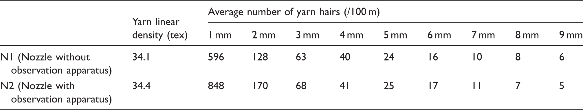
Figure 6 presents the measured air pressure values in the vortex tubes of the nozzles with and without the observation apparatus. When the outlet of the inner tube of the Pitot tube is connected to the pressure gauge, it is the total pressure that is to be measured. However, due to the following reasons, the measured air pressure values may deviate far from the true values of the total pressure
20
: (1) the alignment of the Pitot tube with the flow direction cannot be guaranteed in a swirling flow field; (2) the Pitot tube can cause a considerable disturbance in the local flow field due to its large size relative to the vortex chamber; (3) the turbulence and compressibility effects of the airflow may introduce uncertainty to the measured value. However, since the measurements were carried out under the same conditions for N1 and N2, the influence of mounting the observation apparatus on the airflow field can be qualitatively evaluated by analyzing the difference between the measured air pressure values for the two nozzles. It can be found from Figure 6 that negative pressure exists in the vicinity of the axis of the vortex chamber due to the swirling characteristics of the airflow, which is in accordance with the theoretical result provided by Zhang.
21
The measured air pressure values are generally quite low in the vicinity of the injector exits for both nozzles, that is, below –8000 Pa. The pressure values then rise sharply as the axial position moves downstream to the region in the vicinity of the plane where the cylindrical and conical cavities of the vortex tube meet, that is, 7 mm downstream of the injector exits. The air pressure values then become quite stable as the axial position moves further downstream to the region in the vicinity of the vortex tube outlet. Compared to N1, an obvious alteration of the air pressure for N2 takes place in the region upstream of the endoscope, while the air pressure in the region downstream of the endoscope does not change greatly. For N2, an obvious pressure drop compared to N1 can be observed in the vicinity of the injector exits. Then the air pressure increases sharply at the position 2 mm downstream of the injector exits. The air pressure then falls as the position goes further downstream, while it still has higher values compared to that at the same position for N1 until reaching the position 4 mm downstream of the injector exits. The variation of the air pressure values of N2 compared to N1 together with the intense fluctuation of the air pressure along the axial direction in the upstream of the endoscope might be the reason for the decrease of the yarn quality. However, since the air pressure in the region downstream of the endoscope has not been greatly affected by the use of the observation apparatus, the decrease of the yarn quality previously discussed has been found to be not statistically significant.
Measured air pressure values along the axis of the vortex tubes for the two nozzles. The axial distances from the injector exits to the axis of the working pipe of the endoscope and to the outlet of the vortex tube are 5 and 11 mm, respectively.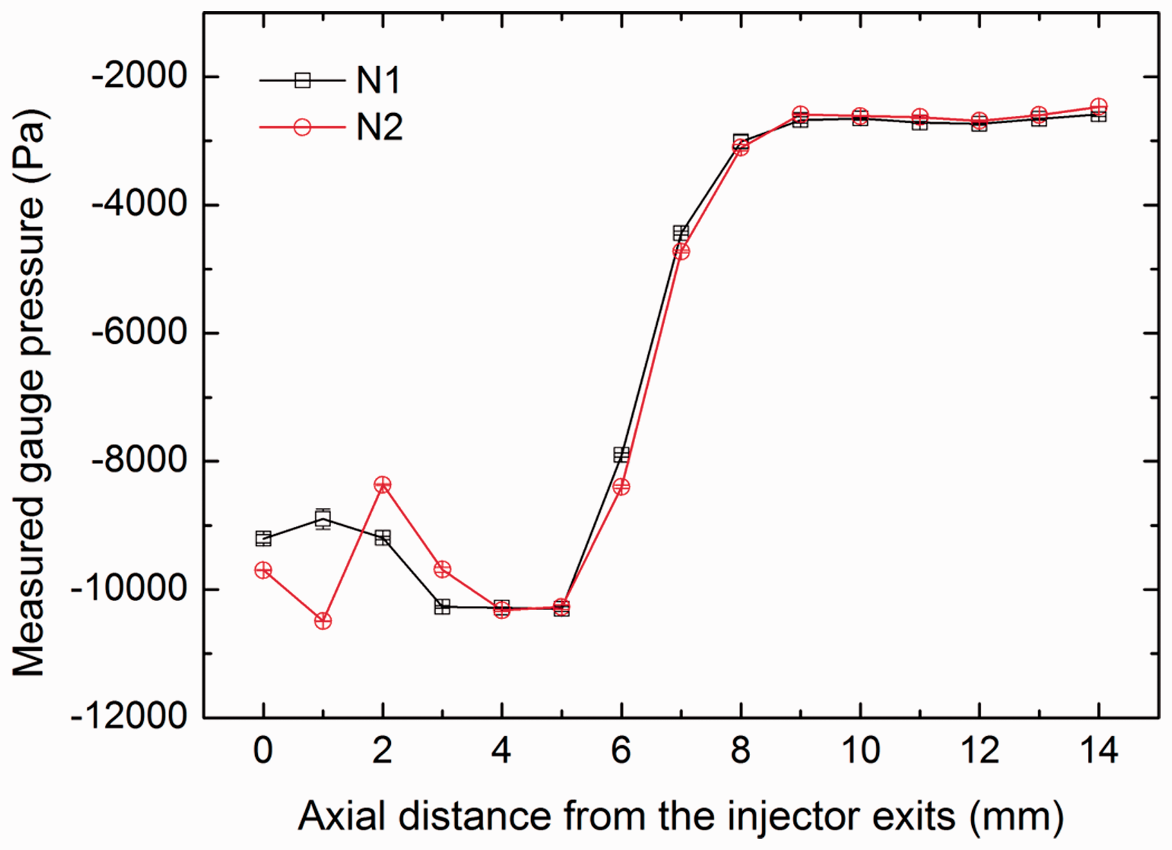
Observation results of the yarn formation process
A large number of images of the yarn formation process were captured in the experiment. Figures 7–10 show selected images that give examples of the typical fiber movements observed. From the experimental images of the yarn formation process, it has been found that the main strand of staple fibers in the upstream of the spindle inlet has wrapped around the copper wire when they enter the field of view of the endoscope. It can also be observed clearly from Figures 7(a)–(d) that the Z-twist has been built in the main strand. Since the nozzle entrance is in a right-handed helical shape, the main strand first wraps around the copper wire in a helical configuration as they converge in the upstream region of the vortex chamber. Then the copper wire is embedded into the main strand. Afterwards, as the main strand moves further to the downstream, false twist is inserted into it by the swirling airflow inside the vortex chamber since the strand is continuous with its two ends nipped by the front rollers and delivery rollers, respectively. The insertion of false twist into the main strand in vortex spinning was previously reported by Pei and Yu
13
based on their numerical simulation results. Here, false-twist insertion into the main strand in the modified vortex spinning for producing core-spun yarns has been observed experimentally. Before the strand enters the spindle inlet, the wrapping of the main strand on the copper wire can be either complete (Figure 10(d)) or incomplete (Figure 7(a)). For the copper wire, it has been found that when the tension on the copper wire is lowered during the spinning process, ballooning of the copper wire takes place. Therefore, considering that the two ends of the copper wire are also nipped, there is a possibility that the copper wire can also be false-twisted by the swirling airflow. However, since the copper wire has been covered by the main strand and a high tension for the wire is usually adopted, it has not been fully confirmed whether false twist is also inserted into the copper wire, and this needs to be studied further. Excluding the main strand that has been false-twisted around the copper wire, the configuration of the observed fibers can be mainly classified into three categories as follows.
Class 1: fibers with their leading ends separated from the main strand and trailing ends embedded in the main strand, as shown in Figure 8. Class 2: fibers with their trailing ends separated from the main strand and leading ends embedded in the main strand, as shown in Figures 9 and 10. Class 3: fibers with both their leading and trailing ends separated from the main strand, as indicated by the white dashed arrows in Figures 8–10.
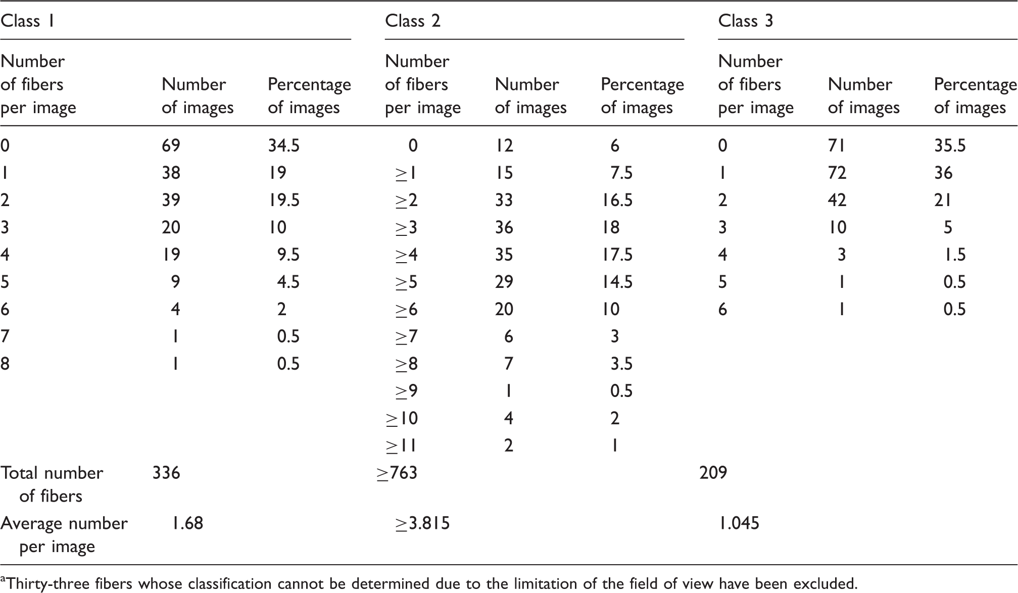
The number of fibers in each class of configuration was counted with caution based on a total of 200 images. The results are listed in Table 3. Since fibers in class 2 are frequently found to appear in tufts, as shown in Figures 9 and 10, their exact number cannot be precisely distinguished from the captured images. As a result, only the ranges of the number of fibers in class 2 are given. It can be found that the number of fibers in class 3 is the lowest among the three classes, while the number of fibers in class 2 is the highest, that is, more than two times that of class 1. Under the forces generated by the tangential and radial velocity components of the swirling airflow as well as the reverse flow from the spindle,8,9 the leading ends of some fibers on the outer periphery of the main strand are separated from the main strand and become free, as shown in Figure 8. However, the force generated by the axial velocity component that points downstream
9
tends to suppress their separation, thus generating a small number of fibers in class 1. The existence of fibers in class 1 in the yarn formation process of vortex spinning has not been reported before. Under the force generated by the tangential and radial velocity components of the swirling airflow, the trailing ends of some fibers on the outer periphery of the main strand are also separated from the main strand and become free, as shown in Figure 9. In addition, the axial flow can also cause the fibers to oscillate22–24 to facilitate the separation of the trailing ends, thus resulting in a large number of fibers in class 2. The swirling air currents then whirl downstream into the gap between the vortex chamber wall and the spindle. Under the force generated by the axial velocity components of the airflow, the trailing ends of a majority of the fibers in class 2 become expanded over the spindle tip, as shown in Figure 10. The leading ends of these fibers are still embedded in the main strand as the strand enters the spindle. In the images in Figures 8–10, there are also a small number of disordered fibers with both ends pulled out from the main strand by the airflow. These fibers fall into class 3. They will be expelled out of the nozzle from the gap between the nozzle wall and the spindle by the air currents and become lost fibers.
Selected images of the formation process of the vortex core-spun yarn showing the false-twisted main strand: (a) t = 4.75 s; (b) t = 8.25 s; (c) t = 20.25 s; (d) t = 43.25. Selected images of the formation process of the vortex core-spun yarn showing the separated leading ends of fibers (indicated by the white solid arrows): (a) t = 11.5 s; (b) t = 27.5 s; (c) t = 30 s; (d) t = 36.25. The white dashed arrow indicates the lost fiber. Selected images of the formation process of the vortex core-spun yarn showing the separated trailing ends of fibers (indicated by the white solid arrows): (a) t = 0.75 s; (b) t = 4.25 s; (c) t = 23.5 s; (d) t = 31.5. The white dashed arrow indicates the lost fiber. Frequency distribution of the number of fibers per imagea Thirty-three fibers whose classification cannot be determined due to the limitation of the field of view have been excluded.


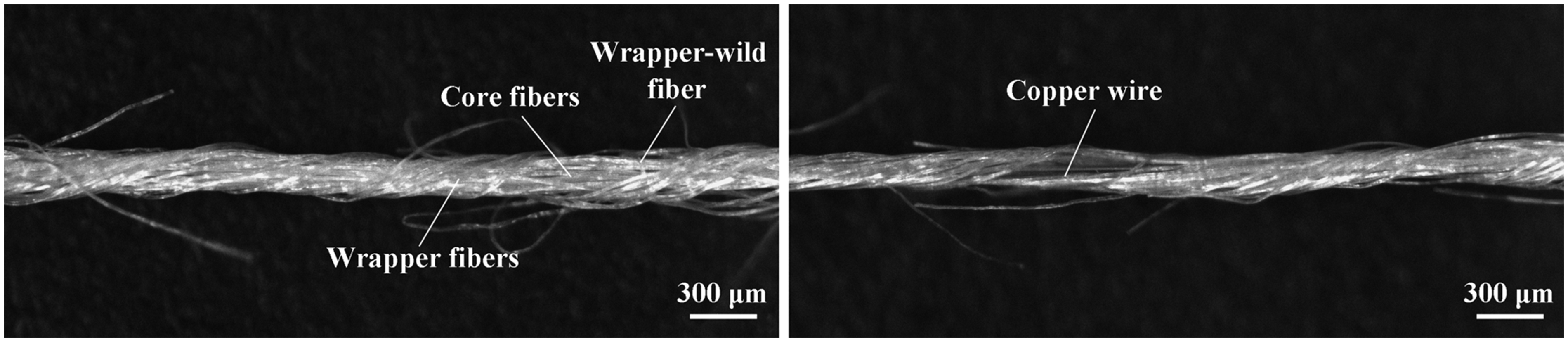
The images taken have shown that high-speed rotation of the fibers in classes 1 and 2 around the main strand takes place. Since the fibers of class 2 are shaded by the spindle after they are drawn into the spindle with the main strand, it is difficult to quantify the rotational characteristics of the fibers in classes 1 and 2 from the captured images. The limited frame rate of the CCD camera used also makes this analysis difficult. However, an analysis of the resultant yarn can help determine the wrapping mechanism of these fibers. Figure 11 presents micrographs of the longitudinal view of the produced core-spun yarn. It can be observed that the copper wire is embedded in the staple fibers in the core region and is covered by twistless fibers that are wrapped by helical fibers. S-twist is observed to be inserted by the helical fibers that wrap the core fibers. Considering the swirl direction of the airflow generated in the vortex chamber (clockwise as observed from upstream to downstream) and the large number of fibers in class 2, it can be known that the helical wrapper fibers are formed from the fibers of class 2 that are driven by the swirling airflow to wrap around the main strand. It can also be found occasionally from the yarn micrographs that a small number of the fibers that wrap around the core fibers are Z-twisted. These fibers have been reported by previous researchers as wrapper-wild fibers.
25
It is known that these wrapper-wild fibers are formed from the fibers of class 1, considering their leading ends being in a free state in the spinning process and the swirl direction of the airflow. As for the main strand and copper wire, since they are false-twisted, the twists in them will be removed after they enter the spindle, the interior of which is shielded from the swirling flow. The main strand then forms the twistless core fibers in the resultant yarn. The tensile load on the yarn can then be shared by both the copper wire in the core and staple fibers in the outer layer, thus increasing the breaking load of the yarn in comparison to the bare copper wire.
3
Selected images of the formation process of the vortex core-spun yarn showing the expanded trailing ends of fibers (indicated by the white solid arrows): (a) t = 3 s; (b) t = 9.25 s; (c) t = 24.5 s; (d) t = 32.25. The white dashed arrow indicates the lost fiber. Micrographs of the longitudinal view of the resultant core-spun yarn.
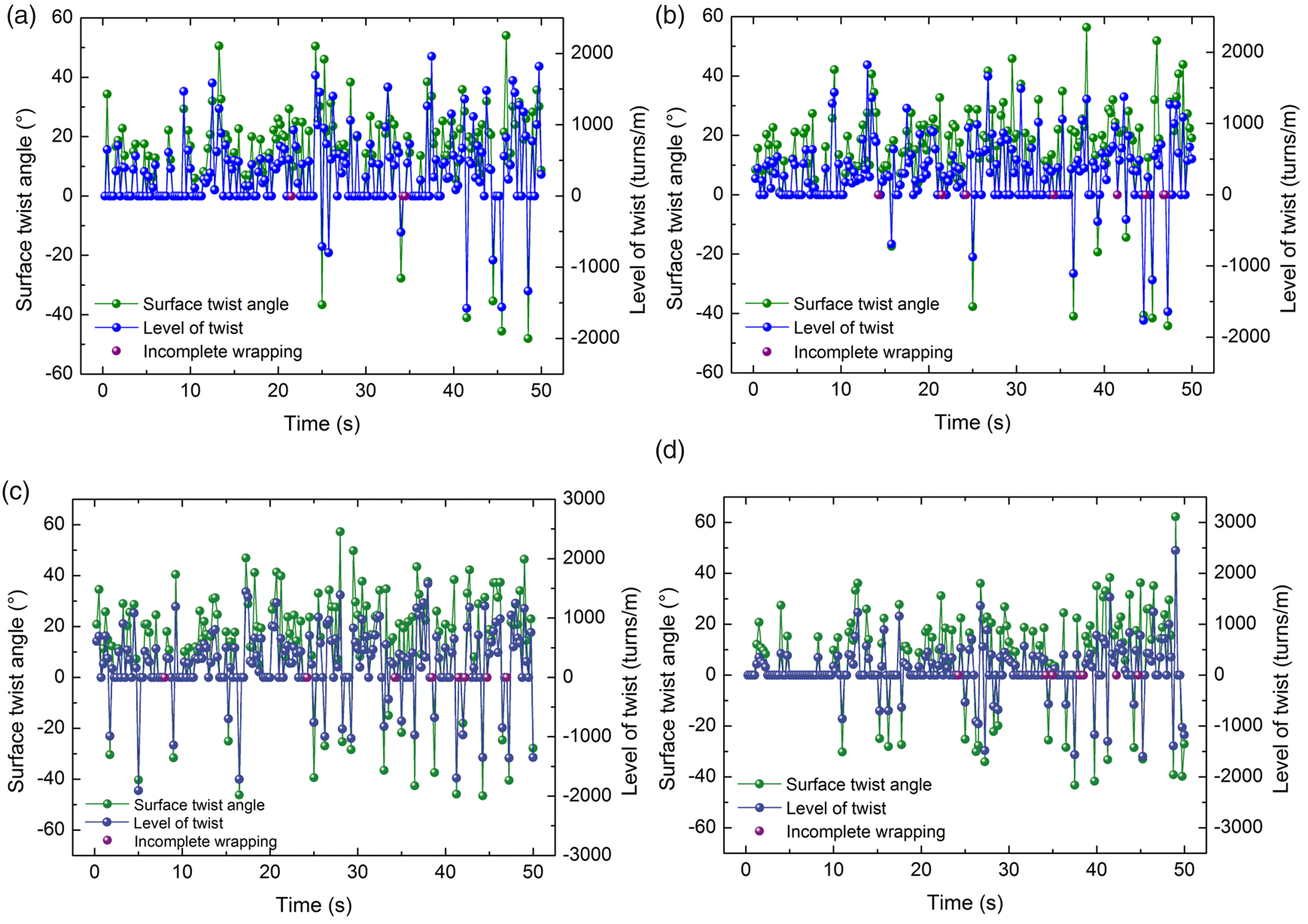
Based on the captured images, the surface twist angle and diameter of the main strand at four positions along the strand, as shown in Figure 7(a), were carefully measured on a time series of images using the Image-Pro Plus 6.0 software, and the level of twist is determined using the following equation
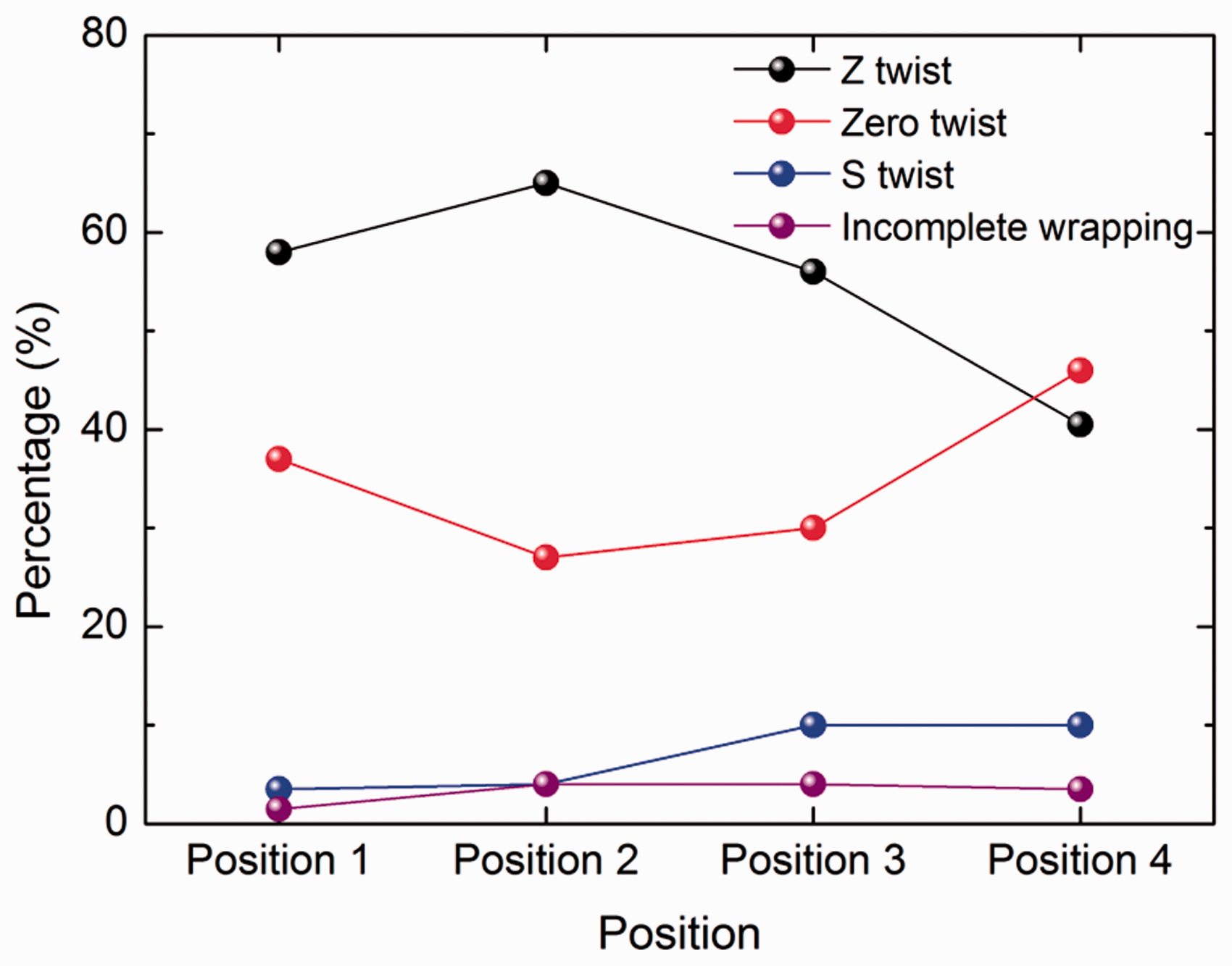
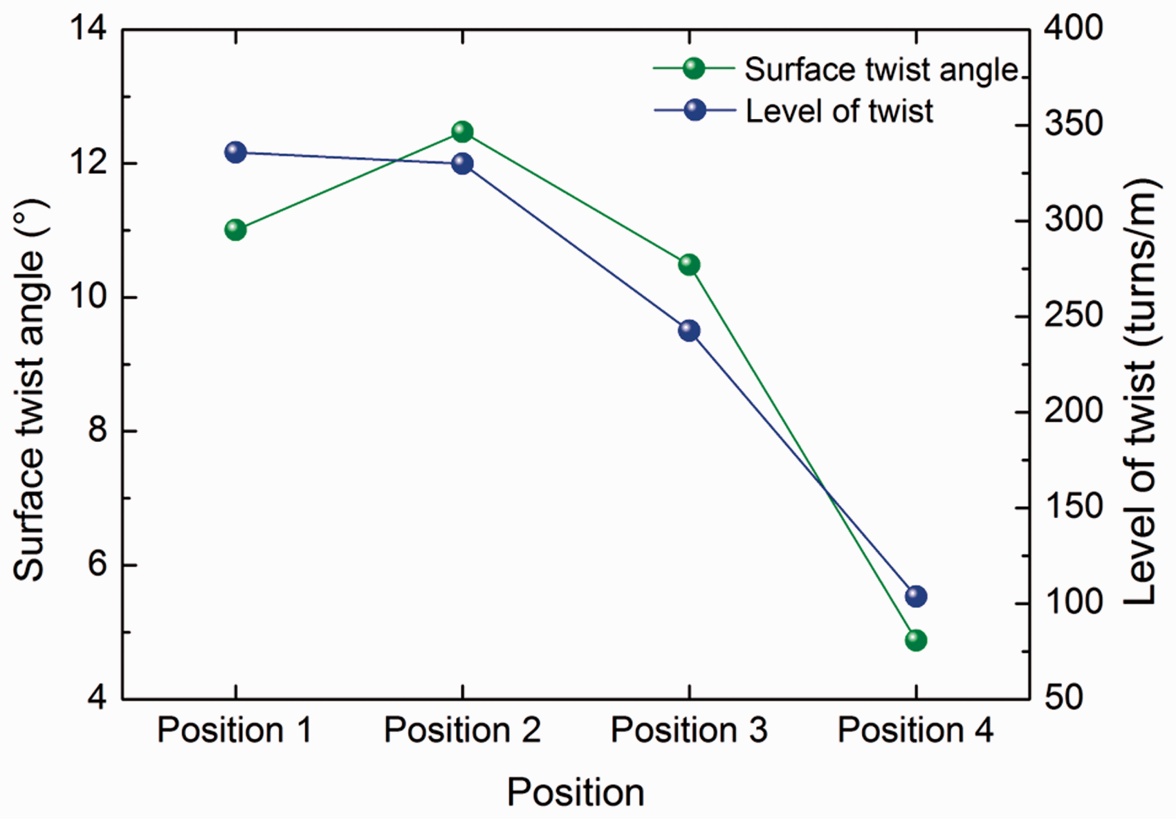
Spatial and temporal distribution of false twist along the main strand: (a) position 1; (b) position 2; (c) position 3; (d) position 4. (Color online only.) Frequency distribution of the Z-twist, zero twist, S-twist, and incomplete wrapping at the four positions along the strand. Average surface twist angle and level of twist at different positions along the strand.
Finally, it is worth mentioning that the wrapping of the expanded trailing ends of fibers in class 2 around the main strand takes place in the vicinity of the spindle inlet as the strand, or the forming yarn, is drawn into the spindle. At the moment when the wrapping motion is taking place, it is still an open question whether the false twist in the main strand has been fully removed, since the forming yarn can no longer be observed after it enters the spindle. The answer to this question determines the subsequent movements of the wrapper fibers relative to the core fibers, and in turn the final structure and properties of the vortex yarn. This remains to be revealed and will be studied in the future.
Conclusions
In this research, a method and apparatus for experimentally observing the yarn formation process of vortex spinning is developed based on a CCD camera fitted with an industrial endoscope that reaches into the nozzle chamber through a small hole on the nozzle wall and two light sources with a sophisticated design and arrangement. Comparative tests on the influence of mounting the observation apparatus on both the air pressure in the nozzle and the yarn quality are performed. Distortion of the air pressure in the upstream of the endoscope due to mounting the observation apparatus has been found, while the yarn quality has not been significantly affected. Based on the proposed method, the formation process of the core-spun yarn manufactured on a modified vortex spinning system at a lowered yarn delivery speed (160 m/min) is observed. It has been found that false twist is inserted into the main strand (core fibers) in the formation process of the core-spun yarn on the modified vortex spinning system. Mostly, the trailing ends of some fibers are separated from the main strand and expand over the spindle tip to wrap around both the core fibers and core wire driven by the swirling airflow inside the nozzle chamber to form the wrapper fibers in the yarn. The generation of a smaller number of fibers with separated leading ends, which will form wrapper-wild fibers in the yarn, is also observed. The temporal distribution of the false twist in the main strand is not stable. A higher level of false twist is built in the main strand in the upstream region of the nozzle chamber, while it is gradually reduced toward the downstream. Twist in the reverse direction in the strand takes place more frequently in the downstream region, that is, in the vicinity of the spindle inlet.
Footnotes
Acknowledgments
We are grateful to the reviewers for their helpful suggestions for revising this paper. We thank Mr Xiangzhang Xiong, Mr Jian Zhou, and Mr Haichen Lu for their assistance with the experiment.
Declaration of conflicting interests
The authors declared no potential conflicts of interest with respect to the research, authorship, and/or publication of this article.
Funding
The authors disclosed receipt of the following financial support for the research, authorship, and/or publication of this article: This work was supported by the Natural Science Foundation of China (Grant No. 11302048), the Shanghai Pujiang Program (Grant No. 16PJ1400400), the Shanghai Natural Science Fund (Grant No. 18ZR1402200), and the Fundamental Research Funds for the Central Universities and DHU Distinguished Young Professor Program.