
Abstract
This paper reports a study on the geometrical analysis of bi-stretch auxetic woven fabric based on a re-entrant hexagonal geometry. The fabric was first designed and fabricated. Then, the fabric was subjected to tensile tests, and changes in the geometry of the fabric structural unit cell at different tensile strains were observed when stretched either in the warp or weft direction. Based on the observations, a geometrical model was proposed for each stretch direction and used to establish the relationship between Poisson’s ratio and tensile strain. The semi-empirical equations for both stretch directions were finally obtained by fitting geometrical parameters with experimental results. It is expected that the semi-empirical equations obtained in this study could be used in the design and prediction of the auxetic behavior of bi-stretch auxetic woven fabrics made with the same type of materials and geometry, but with different values of geometrical parameters.
Auxetic materials have negative Poisson’s ratio (NPR).1–3 Unlike conventional materials, auxetics laterally expand when stretched or laterally contract when compressed. To date, auxetic textile materials including auxetic polymers, fibers, yarns, semi-auxetic yarns and fabrics have been developed and investigated.4–6 Among auxetic textile materials, auxetic fabrics have come to the forefront in modern times and have been gaining more and more interest among textile scientists. Auxetic fabrics are superior to conventional fabrics because of their unusual properties, such as synclastic behavior for better formability, 7 improved comfort, form fitting at joint parts, 8 and increased porosity under stress.9–11 The most straightforward approach to producing auxetic fabrics is to directly use auxetic yarns either in the warp or weft direction and weaving technology. Following this approach, two types of auxetic woven fabrics were made using helix auxetic yarns (HAYs) in the weft. The first type was auxetic woven fabrics produced with plain, twill, and satin weaves. Among the three fabrics, the plain and twill fabrics exhibited most auxeticity and the satin woven fabric was found to be less auxetic. 9 The second type was a plain-woven fabric which exhibited an in-plane NPR up to −0.1, only when the fabric was tested under thickness restrictions using glass plates. 10 Besides these fabrics, a two-ply plain narrow woven fabric was also produced using HAYs as warp yarns. This fabric showed an in-plane NPR of −0.1 at 32% tensile strain and increased porosity at 80 N of applied tension. 12 Recently, plied auxetic yarns were used to fabricate woven fabrics, and it was found that the alternative arrangement of S- and Z-twisted plied auxetic yarns in a woven fabric could produce a higher NPR. It was also reported that the NPR effect of HAYs could not be fully utilized in woven fabrics due to constraints of the woven fabric structure. 13
The other approach to producing auxetic fabrics involves using non-auxetic yarns and knitting or weaving technology to produce auxetic fabrics. Because the auxetic behavior is linked with the geometrical arrangements of the structural units, this approach is based on the technique of realizing auxetic geometries into fabric structures. 5 The knitted fabrics produced by adopting this approach include auxetic warp knitted fabrics made from rotational hexagonal loops geometry, 14 double arrowhead geometry, 15 re-entrant hexagonal (REH) geometry,16–18 and spacer structure, 19 and auxetic weft knitted fabrics produced with foldable geometries,20–22 rotating rectangle geometry, 21 REH geometry, double arrowhead geometry, 23 and tubular fabrics. 24 However, these auxetic fabrics still have certain limitations. Low structural stability, higher thickness, low modulus, and low strength are some of drawbacks of these fabrics, which restrict their applications in garments and other areas. Adopting the same approach, uni-stretch auxetic woven fabrics were also produced based on foldable geometries, rotating rectangle geometry, and REH geometry 2 through the creation of the phenomenon of differential shrinkage or non-uniform contraction profile within the fabric structural unit cell using elastic and non-elastic yarns together with loose and tight weaves. However, these fabrics also have some major drawbacks, such as extensibility and a smaller auxetic effect only in one direction. Most recently, it was reported that developing bi-stretch auxetic woven fabric having extensibility and a larger auxetic effect in both directions is possible using the same technique as used in development of uni-stretch auxetic woven fabrics. The reported fabrics were produced based on the foldable geometry with NPR up to −0.36 and −0.27 when stretched along the warp and weft direction, respectively. 25 Besides this, the development of a new bi-stretch auxetic woven fabric based on an approximation of REH geometry was also reported. 26 The study has shown that the developed bi-stretch woven fabrics have a NPR effect or auxetic effect in both principal directions. These fabrics may have great potential for clothing applications, such as highly stretchable sport garments like a riding kit for bikers which can cast itself to different body shapes, 27 stretchable textile carriers, 28 and denim products providing comfort and the ability to mold and move easily in accordance with body movements, 29 etc. Although the reported studies can provide systematic information on the design and fabrication of these fabrics, the relationships between the geometrical parameters and tensile deformation are still not explored. In this paper, a geometrical analysis of such fabrics is conducted to establish these relationships, since they are very helpful in design and prediction of the auxetic effect of fabrics for specific applications. The fabric based on REH geometry was chosen for this analysis because this geometry has already been reported as a potential candidate among auxetic geometries which can easily be realized into woven fabric structures. 2 In addition, because the unit cell of REH geometry is simple, the geometrical analysis can be carried out more straightforwardly. In order to facilitate the geometrical analysis, the fabric was first tested under a uniaxial extension to observe the changes in the geometry of its structural unit cell at different tensile strains. Then, based on the observations, a geometrical model was proposed for each stretch direction. From the geometrical analysis, the semi-empirical equations between the Poisson’s ratio (PR) and tensile strain were finally established for both weft and warp stretch directions. The study shows that the established semi-empirical equations fit well with experimental results. Therefore, they could be used in the design and prediction of bi-stretch auxetic woven fabrics with different values of geometrical parameters.
Experimental details
Design and fabrication of auxetic woven fabrics
Before conducting the geometrical analysis, bi-stretch auxetic woven fabrics based on REH geometry were first designed and fabricated. A special interlacement pattern having loose and tight weaves at different sections of the unit cell, as reported by the authors
26
and shown in Figure 1, was used to achieve the geometrical configurations of the hexagonal unit cells into the fabric structure. It can be seen that the unit cell of the interlacement pattern includes three sections A, B, and C, which are formed with different weaving tightness. While the sections A at ribs 1–3 and 2–4 are woven with loose (4/1) weave, the sections B next to the ribs 1–3 and 2–4 are woven with tight (1/1) weave. The central section C is also woven with loose weave in such a way that the warp yarns are free of interlacement and raise above the weft yarns alternately. Thus, the order of weaving tightness of the three sections is B > A > C.
Schematic illustration of loose and tight weave placement in the unit cell of the designed interlacement pattern.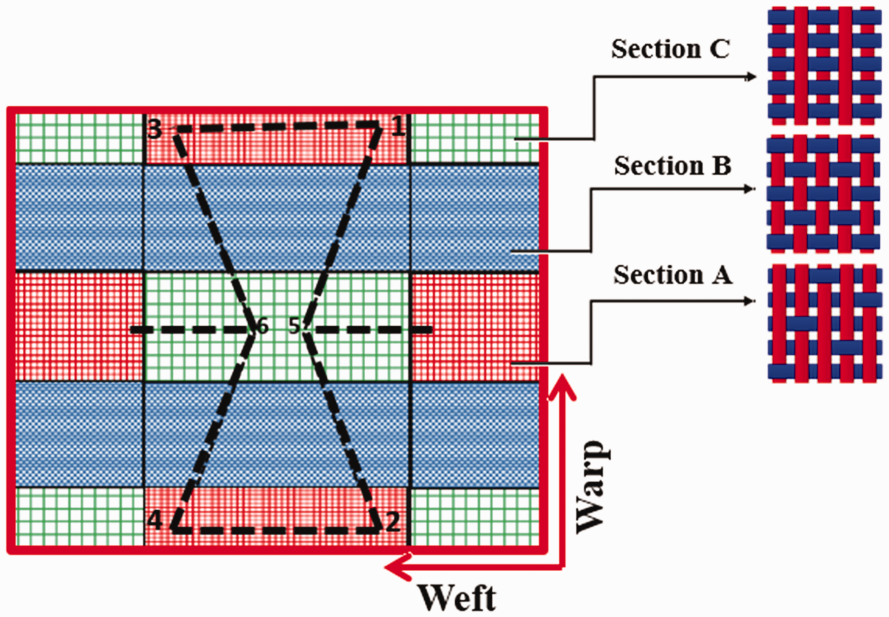
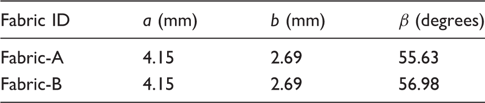
One of the fabrics produced based on this interlacement pattern is shown in Figure 2(a), in which the three different sections of the unit cell, namely A, B, and C are clearly indicated. A unit cell of the fabric geometry is shown in Figure 2(b), in which segments 1–3 and 2–4 are the horizontal ribs named as a, whereas segments 1–5, 5–2, 3–6, and 6–4 are the diagonal ribs named as b. The basic unit cell of the fabric structure with the outline of the hexagonal unit cell is shown in Figure 2(c). When this structure is stretched in either direction, the diagonal rib segments b will move to the horizontal disposition, leading to an increase in the distance between points 5 and 6. As a result, the dimensions of the whole structure increase and the auxetic effect is achieved. It can be seen that the geometrical parameters a,b and angle β formed between a and b determine the geometrical features of the structure at the initial state. In order to get the semi-empirical equations and verification of the semi-empirical equations, two fabrics—namely Fabric-A and Fabric-B—with different values of β were designed and fabricated on a rapier weaving machine (Model: SL8900S) manufactured by CCI Intech (Taiwan), equipped with the option of using two warp beams with separate controls for warp yarn let off motion and warp yarn tension for both beams. A 14.8 Tex core spun cotton spandex yarn was used as an elastic yarn and 14.8 Tex cotton spun yarn was used as a non-elastic yarn. The core of the elastic yarn was a 4.44 Tex spandex filament. The weft and warp thread densities used were 31.50/cm and 25.20/cm, respectively. In addition, polyvinyl alcohol (PVA)—having specifications pH: 5–7; hydrolysis: 86.5–89; viscosity: 20.5 to 24.5 CP’s; and ash content: 0.7%—was applied on the surface of the warp yarns as a sizing material.
A bi-stretch auxetic woven fabric based on REH geometry. (a) Fabric face showing geometrical configuration, (b) Hexagonal unit cell and (c) Basic unit of fabric structure with the outline of the hexagonal unit cell.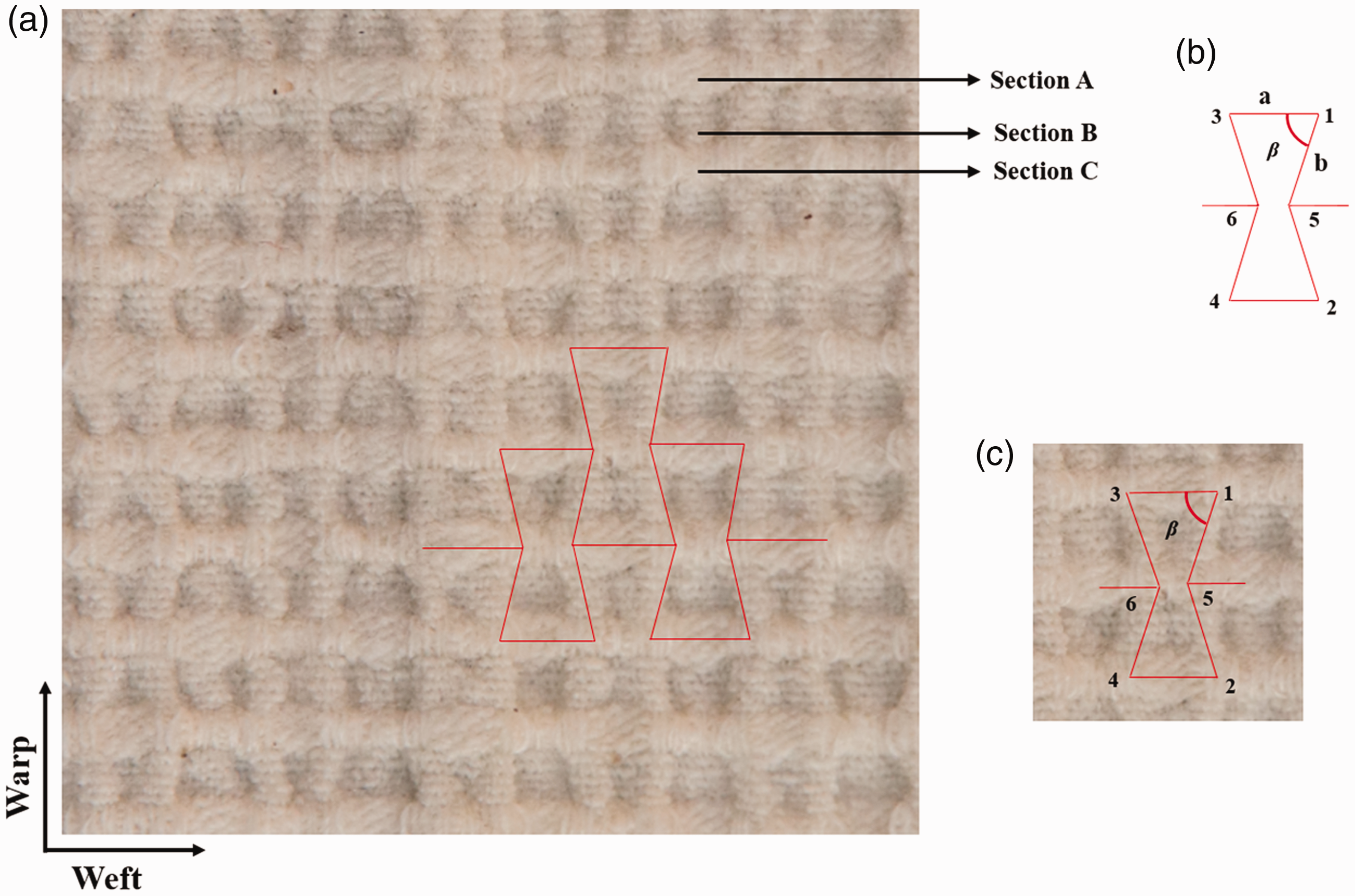
Geometrical parameters of bi-stretch auxetic woven fabrics based on REH geometry
Tensile tests
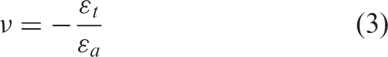
The tensile tests were carried out in both the weft and warp directions on an Instron 5566 tensile testing machine. The capacity of the load cell used was 10 kN. The gauge length and tensile speed were set at 150 mm and 30 mm/min, respectively, and jaws of size 76.2 × 25.4 mm were used. The testing setup is shown in Figure 3. A set of three fabric strips of dimension 50 × 200 mm were cut for each sample with the length along the warp and along the weft directions, respectively. The central point of the fabric strip was first located and then four points were marked with the central point at 20 mm to facilitate recording the information of fabric deformation during the tensile test. The tensile test was video recorded using a camera (Canon EOS 800D). The video resolution used was Full HD (1920 × 1080). The photographs were then extracted with a time interval of 15 s or after each 5% extension. The distances of the marks in the photographs were measured via a screen ruler for both the free state and stretched state with an accuracy of 4.66 px/mm. The engineering strains of the fabric structure in both the tensile direction and transversal direction were then calculated based on the measured distances using equations (1) and (2), respectively.
Testing setup for the tensile test of the auxetic woven fabric.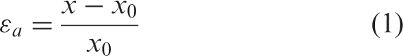
The PR was calculated at every 5% of tensile strain. This time of measurement was chosen to observe any change in dimensions even within 5% of tensile strain. The PR versus tensile strain curve was generated using the data from the tensile test.
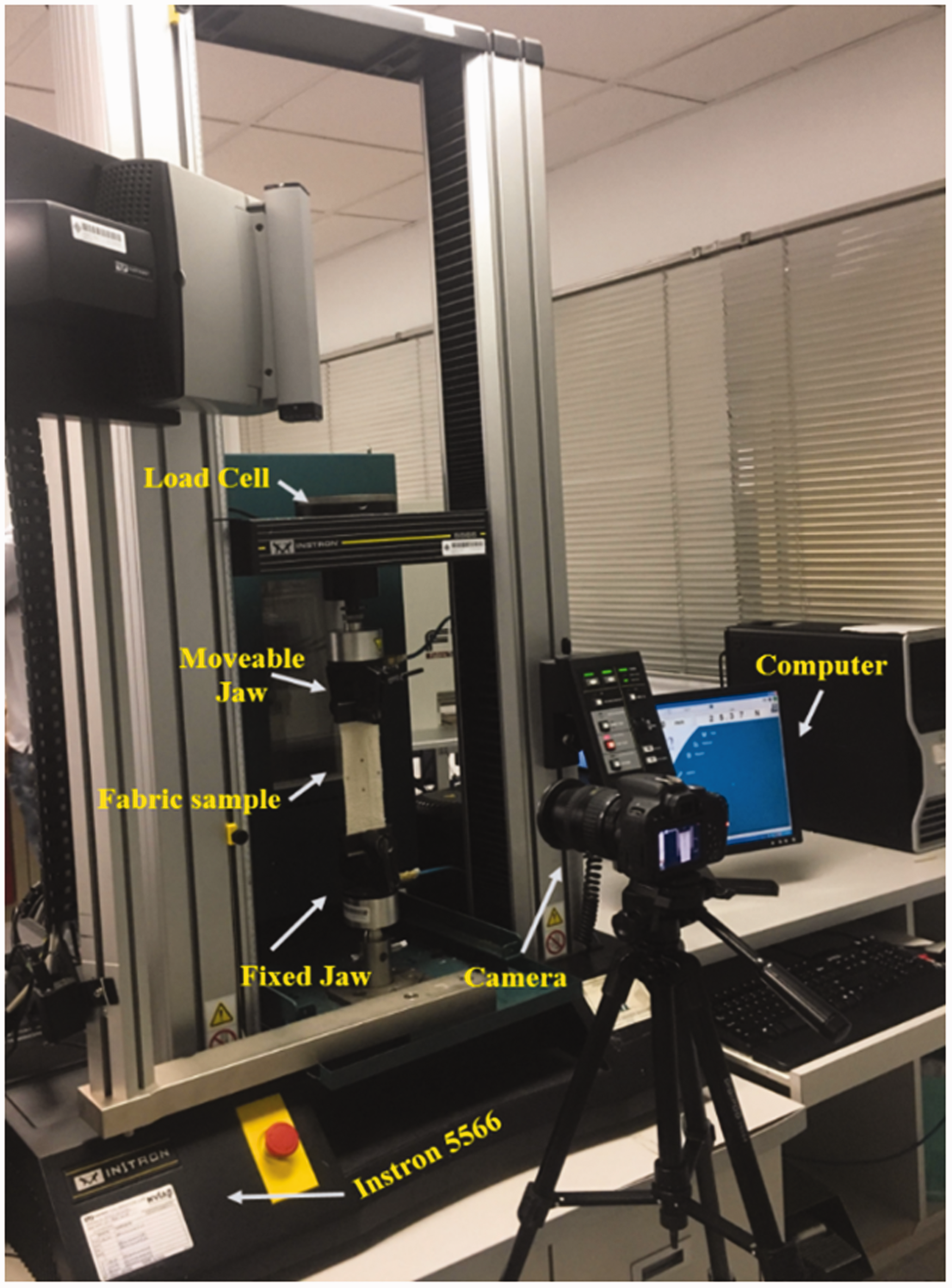
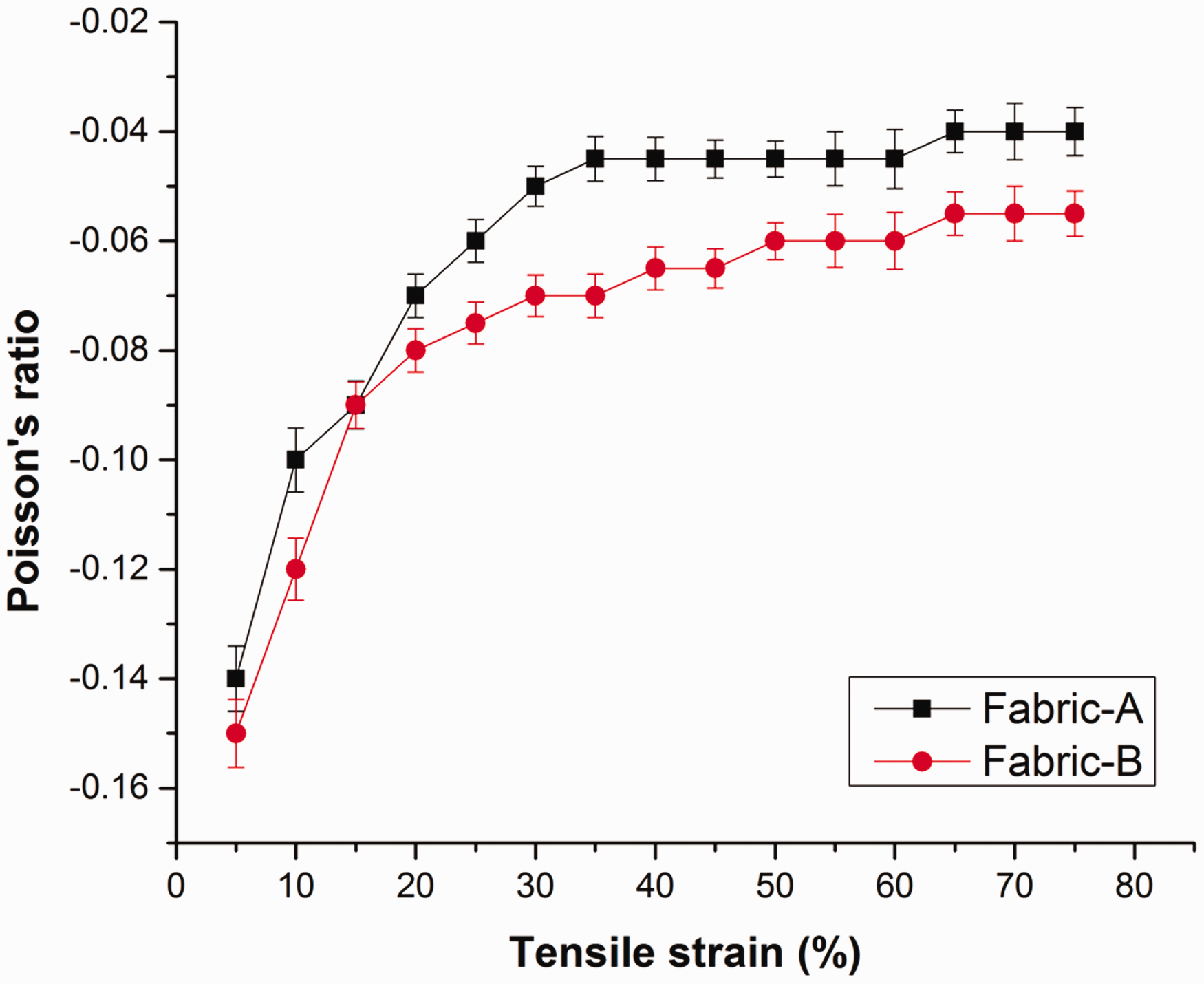
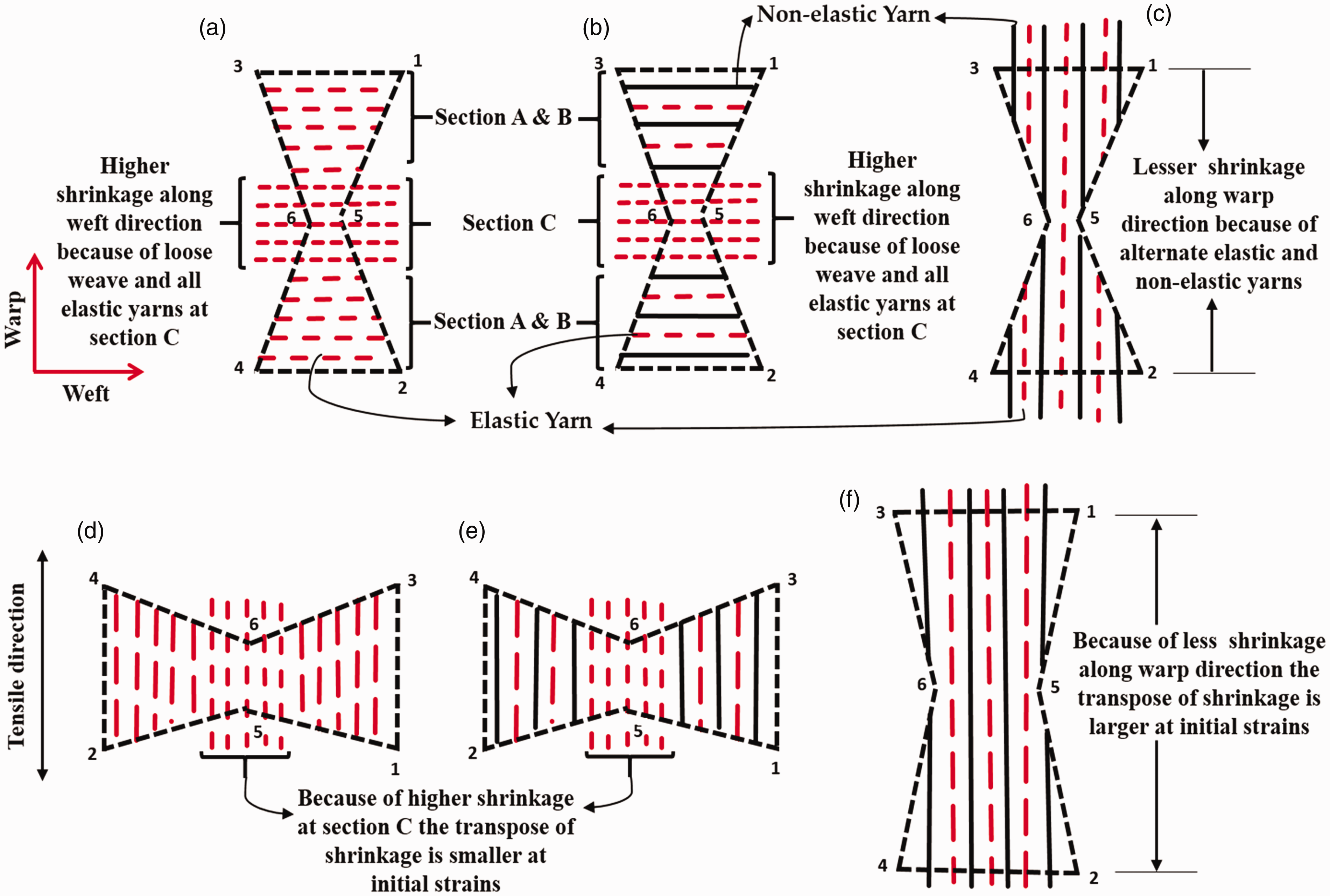
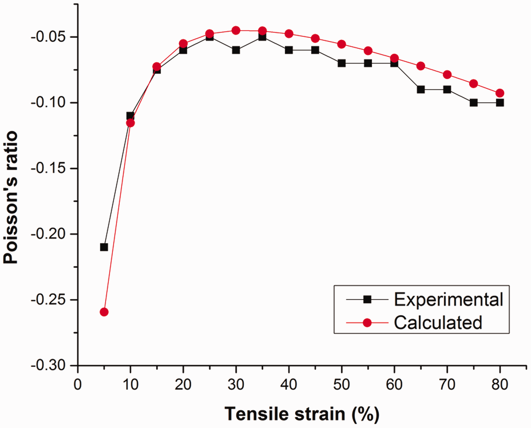
Upon stretching along the warp or weft direction, the fabric undergoes tensile deformation and the shrinkage is transposed. This makes the distance between point 5 and 6 to increase and the fabric expands in the transverse direction producing the auxetic effect. The PR versus tensile strain curves of the two fabrics, when stretched in the two principal directions, are shown in Figures 4 and 5, respectively. It can be seen that the auxetic effect is produced in both the warp and weft directions. However, the auxetic effect when stretched in the warp direction is higher than that when stretched in the weft direction. It can also be seen that the auxetic effect of the fabric rapidly decreases with the increase of tensile strain at the initial stage of stretch and reaches its lowest level when the strain reaches about 30%. Then, the auxetic effect almost keeps stabilized when stretched in the weft direction and increases when stretched in the warp direction. This behavior can be explained by considering the arrangements of the elastic and non-elastic yarns and shrinkage within the hexagonal unit cell along the warp and weft direction, as shown in Figure 6. To make the understanding easier, only the yarn lengths within the hexagonal unit cell are shown in Figure 6, in which the elastic and non-elastic yarns are represented by the dashed red and solid black lines, respectively. It can be seen that, because of more elastic yarns at section C in the weft direction, there is higher shrinkage along the weft direction than that along the warp direction. Therefore, when the fabric is stretched along the weft direction, because of the higher shrinkage along this direction, smaller initial transposition of shrinkage is achieved and, after this, the stretching force is consumed in straightening of yarns under tension. Moreover, because of the higher shrinkage at section C, a greater length of yarn under tension needs to be stretched before an increase in the distance between points 5 and 6. Consequently, the increase in the transverse dimension is delayed and occurs at higher strains which results in a smaller auxetic effect. In addition, the increase in the transverse dimensions occurs simultaneously with the increase in tensile strain which results in a stabilized auxetic effect. On the other hand, when the fabric is stretched along the warp direction, due to the smaller shrinkage along this direction, a higher transpose of shrinkage is achieved at initial tensile strain, resulting in a higher initial auxetic effect. After initial transposition, the stretching force is consumed in straightening of yarns under tension, during which the auxetic effect decreases. However, because of smaller shrinkage, the straightening of yarns under tension is achieved earlier, resulting in higher transposition of shrinkage and the auxetic effect increases.
Poisson’s ratio–tensile strain curves of fabrics when stretched along the warp direction. Poisson’s ratio–tensile strain curves of fabrics when stretched along the weft direction. Explanation of the transpose of shrinkage along the warp and weft directions. (a) Unit cell in the free state showing the weft yarn arrangement in Fabric-B, (b) Unit cell in the free state showing the weft yarn arrangement in Fabric-A, (c) Unit cell in the free state showing the warp yarn arrangement in Fabric-A and Fabric-B, (d) Unit cell of Fabric-B at initial strain stretched along the weft direction, (e) Unit cell of Fabric-A at initial strain stretched along the weft direction and (f) Unit cell of Fabric-A and Fabric-B at initial strain stretched along the warp direction.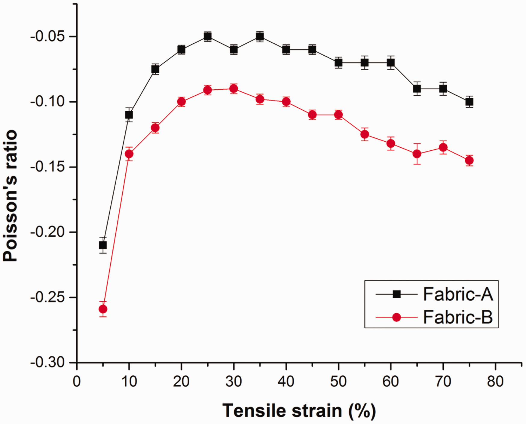
Deformation behavior when stretched in the warp direction
Experimental observations
To observe the deformation behavior of the fabric upon stretching, photos were taken at different tensile strains during the tensile test. Figure 7 shows a five times magnified view of photos of the Fabric-B unit cell at different tensile strains when stretched in the warp direction. The unit cell of the fabric structure is outlined by dashed lines in all photos. When the fabric is stretched in the warp direction, the shrinkage at section C transposes and the diagonal segments b at sections B tend to move toward the horizontal disposition. Because of this, the angle β formed between segments a and b increases. Therefore, the tensile strain is dependent mainly on the angle β. Furthermore, the horizontal disposition of the diagonal segments makes the distance between points 5 and 6 to increase from the center in the transverse direction. This increases the dimensions of the whole fabric structure in the transversal direction to achieve the auxetic effect of the fabric. Comparing photos of the fabric when stretched in the warp direction, it can be observed that the deformation of the fabric is likely to be the deformation of the REH unit cell stretched along the long side of the unit cell, as outlined in the photos. Therefore, a REH geometrical model is proposed to estimate the deformation behavior of the fabric structure when stretched in the warp direction.
Photos of Fabric-B taken at different tensile strains when stretched in the warp direction.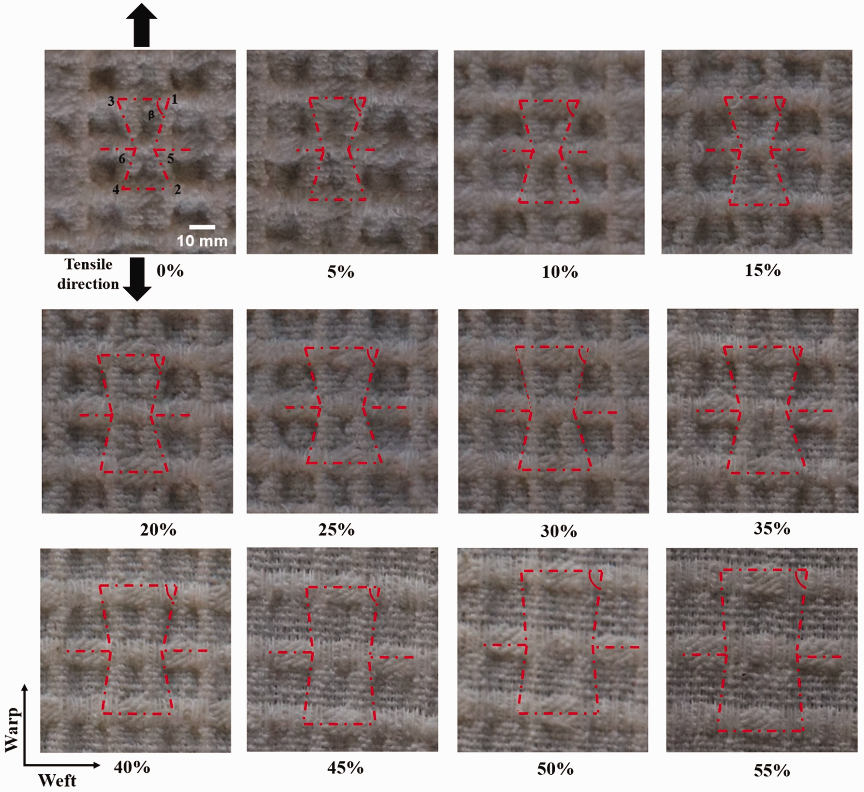
Geometrical analysis
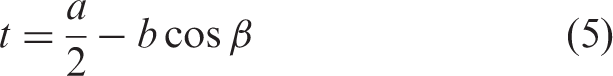
To establish the relationship between tensile strain and the PR of the developed fabric, a geometrical analysis was carried out. A geometrical model, when the fabric is stretched in the warp direction, is proposed, as shown in Figure 8. For simplicity, the following assumptions were first made:
Geometrical model. (a) The re-entrant hexagonal (REH) geometry of the unit cell in the free state and (b) Deformation of the unit cell under extension in the warp direction. The hexagonal unit cells of the fabric structure have the same shape and size and they exhibit the same behavior when the fabric undergoes extension in the warp direction. The deformation behavior of the fabric when the fabric undergoes extension in the warp direction can be analyzed by considering the deformation behavior of the hexagonal unit cell under extension along the long side of the unit cell. All the rib segments are not kept constant due to easy deformation of the fabric structure.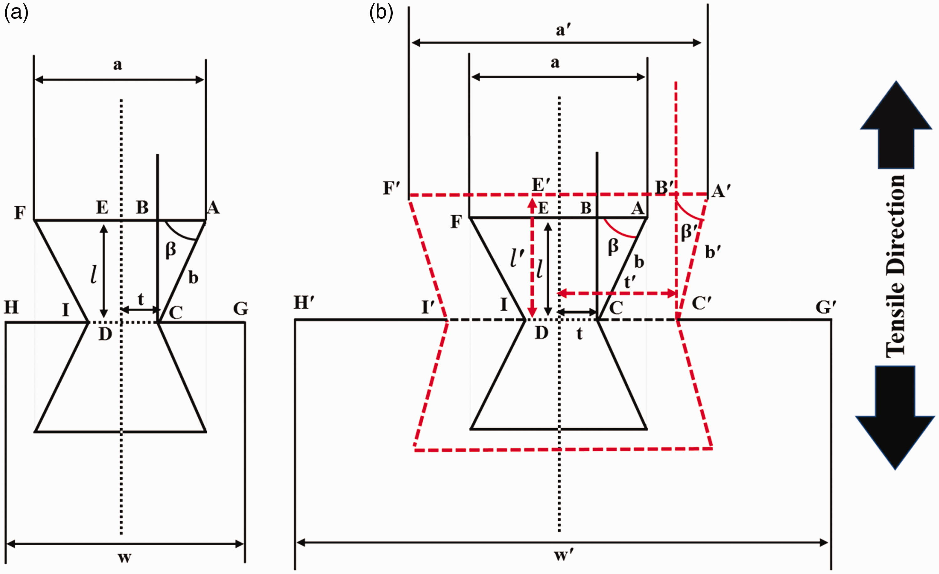
Figure 8(a) shows the proposed geometrical model in the free state, and Figure 8(b) shows the proposed geometrical model in the free state (solid lines) as well as a state under extension (dashed lines).
Considering the geometry of the unit cell before the extension, according to Figure 8(a), 

Similarly, considering the geometry of the unit cell after extension, the following relationships can be made between the geometrical parameters

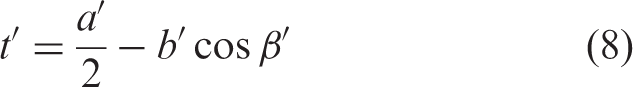

It can be observed that upon extension in the tensile direction, l changes to 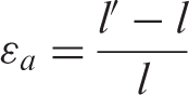
Substituting l and 
From equation (10), the relationship of 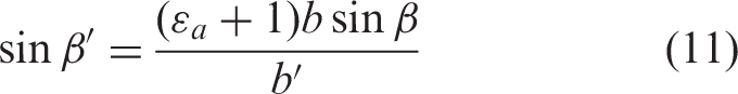
From the relationship 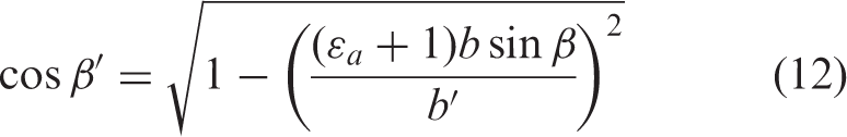
Upon extension due to the horizontal disposition of 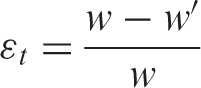
Substituting w and 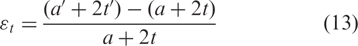
Substituting t and 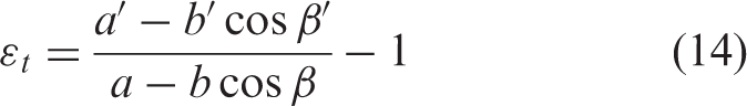
Substituting 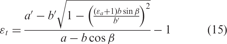
Substituting equation (15) into equation (3) gives equation (16), which can be used to calculate the PR of the fabric when stretched in the warp direction
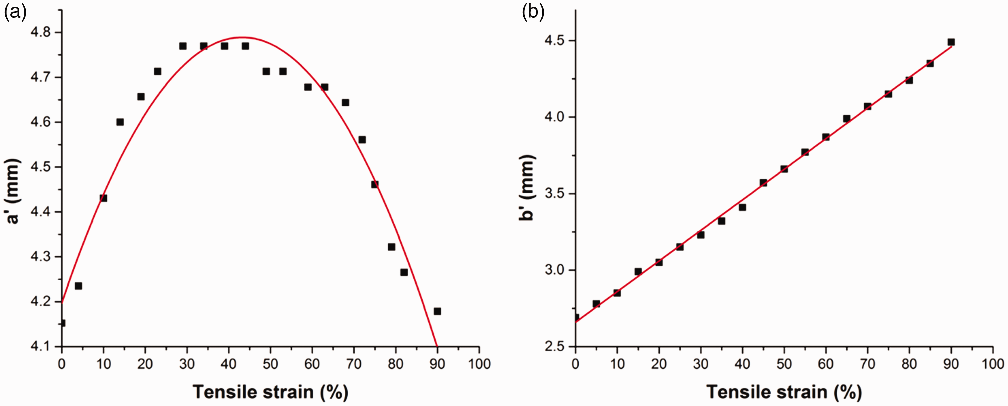
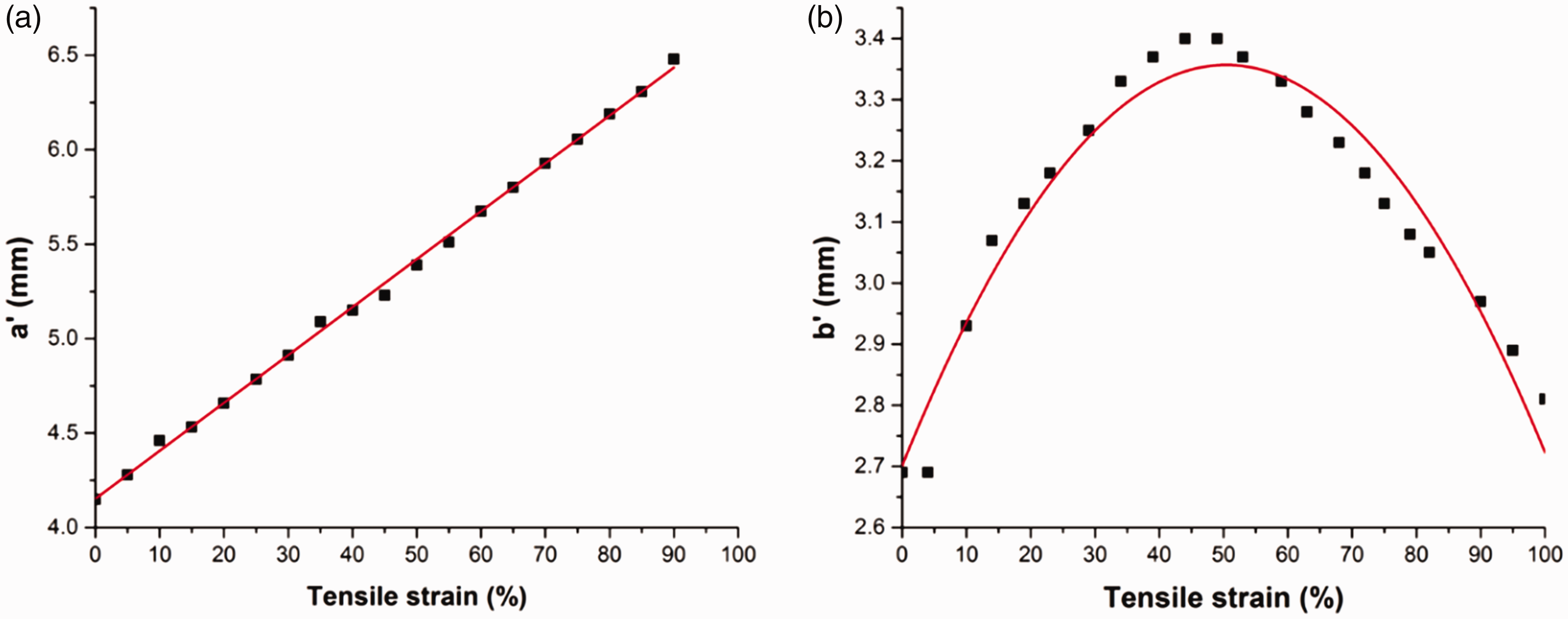
Variation trend when stretched in the warp direction. (a) Trend of 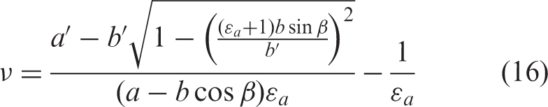


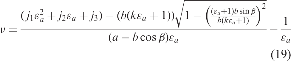
From equation (19), it can be determined that there are four constants 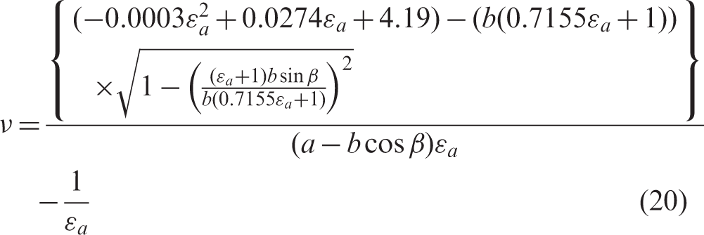
Both the calculated and experimental curves of PR vs. tensile strain when the fabric is stretched in the warp direction are shown in Figure 10. It can be seen that the calculated curve fits well with the experimental results. To verify equation (20), the experimental results for Fabric-A with different values of β when stretched in the warp direction are compared with the calculated curve that is obtained using equation (20), as shown in Figure 11. It can be seen that the calculated curve fits well with the experimental results. Therefore, equation (20) is verified and can be used to predict the PR (when the fabric is stretched in the warp direction) of bi-stretch auxetic woven fabric made of the same type of materials and geometry but with different geometrical parameters.
Comparison between theoretically calculated curves and experimental results for Fabric-B when stretched in the warp direction. Comparison between theoretically calculated curves and experimental results for Fabric-A when stretched in the warp direction.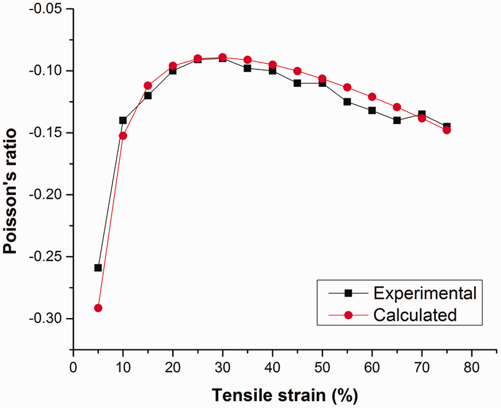
Deformation behavior when stretched in the weft direction
Experimental observations
Figure 12 shows five times magnified photos of Fabric-B at different tensile strains when stretched in the weft direction. The unit cell of the fabric structure is outlined in all photos. When the fabric is stretched in the weft direction, the tensile yarns tend to straighten, transposing the shrinkage at sections A (segments 1–3, 2–4 or a) and at section C. Because of the shrinkage transposing, the diagonal segments b at section B move towards the horizontal disposition and translate to the straight form. This horizontal disposition of the diagonal segments makes the distance of points 5 and 6 from the center to increase in the tensile direction. Therefore, the tensile strain is mainly dependent on the change in the distance of points 5 and 6 from the center. Furthermore, because of the increase in the distance of points 5 and 6 from the center, the angle β formed between segments a and b increases, which increases the transverse dimensions to achieve the auxetic effect. Comparing photos of the fabric when stretched in the weft direction, it can be observed that the deformation of the fabric is likely to be the deformation of the REH unit cell stretched along the short side of the unit cell, as outlined in the photos. Therefore, a REH geometrical model is proposed to estimate the deformation behavior of the fabric structure when stretched in the weft direction.
Photos of Fabric-B taken at different tensile strains when the fabric is stretched in the weft direction.
Geometrical analysis
Figure 13 shows a proposed geometrical model when the fabric is stretched in the weft direction. To make the analysis simple, the following assumptions are first made.
Geometrical model. (a) The re-entrant hexagonal (REH) geometry unit cell in the free state and (b) Deformation of the unit cell under extension in the weft direction. The hexagonal unit cells of the fabric structure have the same shape and size and they exhibit the same behavior when the fabric undergoes extension in the weft direction. The deformation behavior of the fabric can be analyzed by considering the deformation behavior of the hexagonal unit cell under extension along the short side of the unit cell. All the rib segments are not kept constant due to easy deformation of the fabric.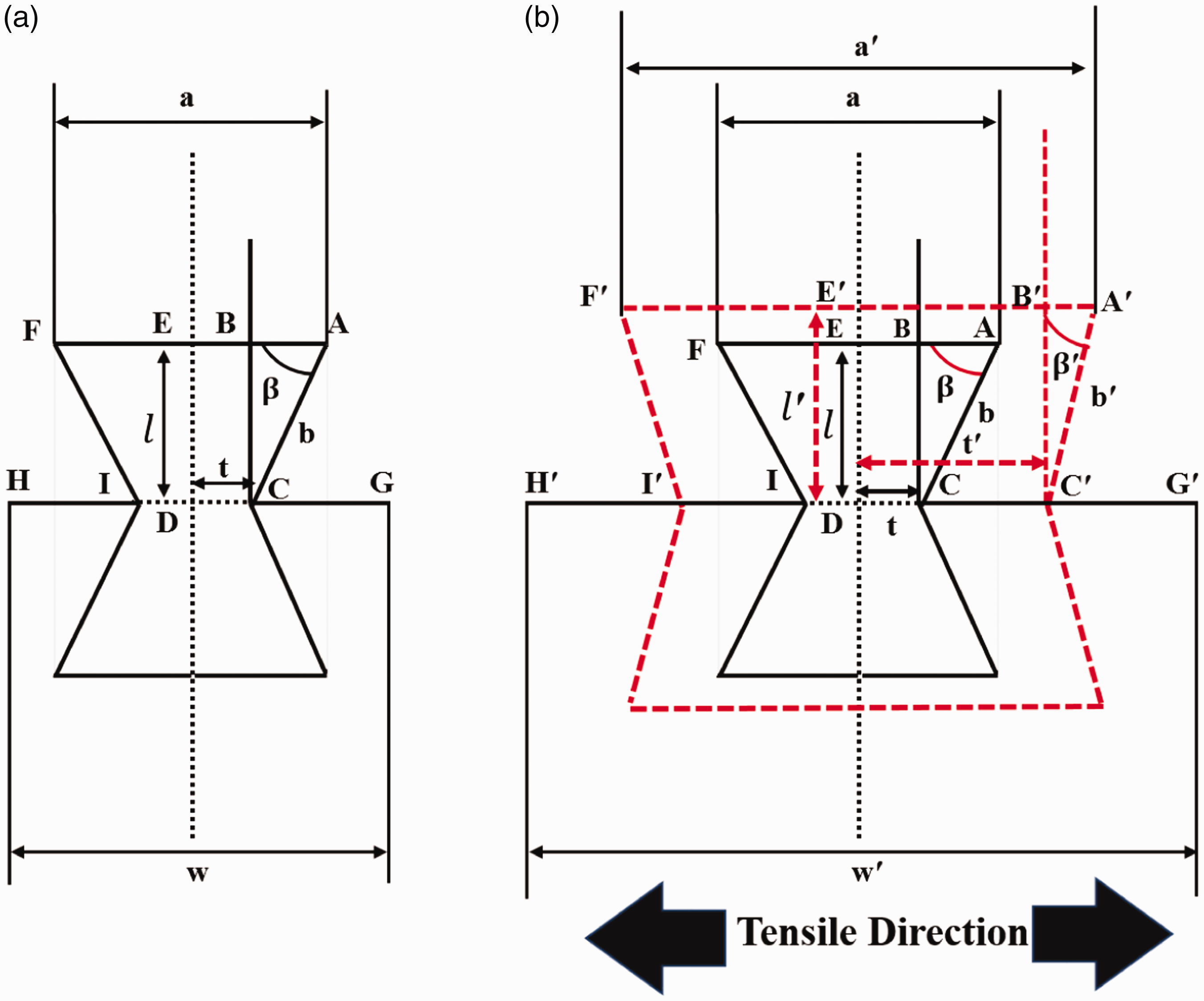
Figure 13(a) shows the proposed geometrical model in the free state and Figure 13(b) shows the proposed geometrical model in the free state (solid lines) as well as a state under extension along the short side of the unit cell (dashed lines). Considering the geometry of the unit cell before the extension, according to Figure 13(a)
It can be observed that upon extension in the weft direction, w increases and changes to 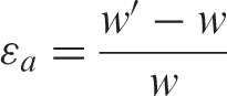
Substituting w and 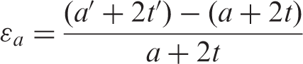
Substituting t and 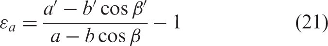
From equation (21), the relationship of 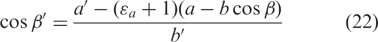
From the relationship of 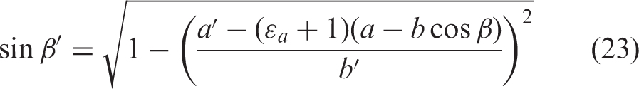
It can also be observed that upon extension in the weft direction, due to the horizontal disposition of 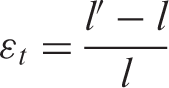
Substituting l and 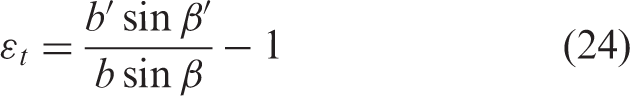
Substituting 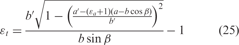
Finally, the PR ν when stretched in the weft direction can be calculated by substituting equation (25) into equation (3)
Variation trends when stretched in the weft direction. (a) Trend of 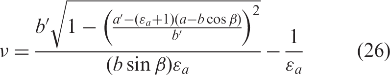


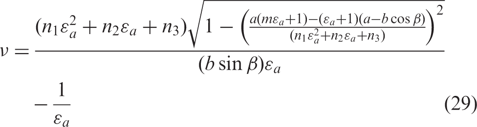
In equation (29), it can be seen that there are four constants m, 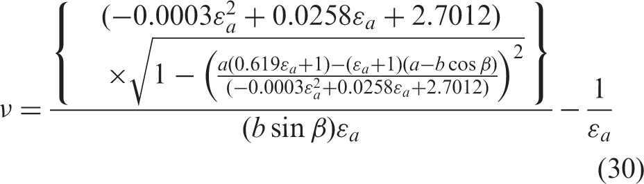
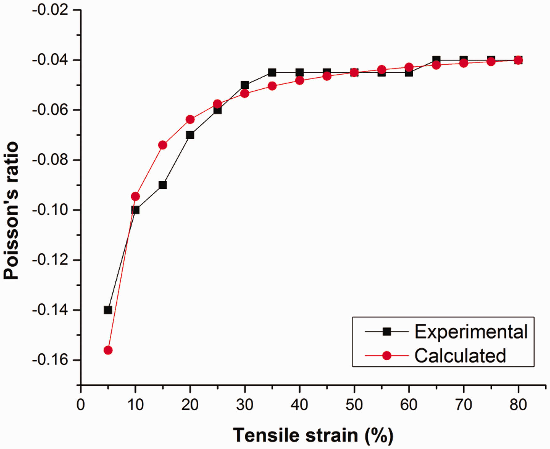
Both the calculated curve and experimental values of the PR are shown in Figure 15. It can be observed that the calculated curve fits well with the experimental results. To verify equation (30), the experimental results for Fabric-A having different values of β when stretched in the weft direction are compared with the calculated curve that is obtained using equation (30), as shown in Figure 16. The calculated curve fits well with the experimental results. Therefore, equation (30) is verified and can be used to predict the PR of bi-stretch auxetic woven fabric made of the same type of materials and geometry but with different values of geometrical parameters when stretched in the weft direction.
Comparison between the theoretically calculated curves and experimental results for Fabric-B when stretched in the weft direction. Comparison between the theoretically calculated curves and experimental results for Fabric-A when stretched in the weft direction.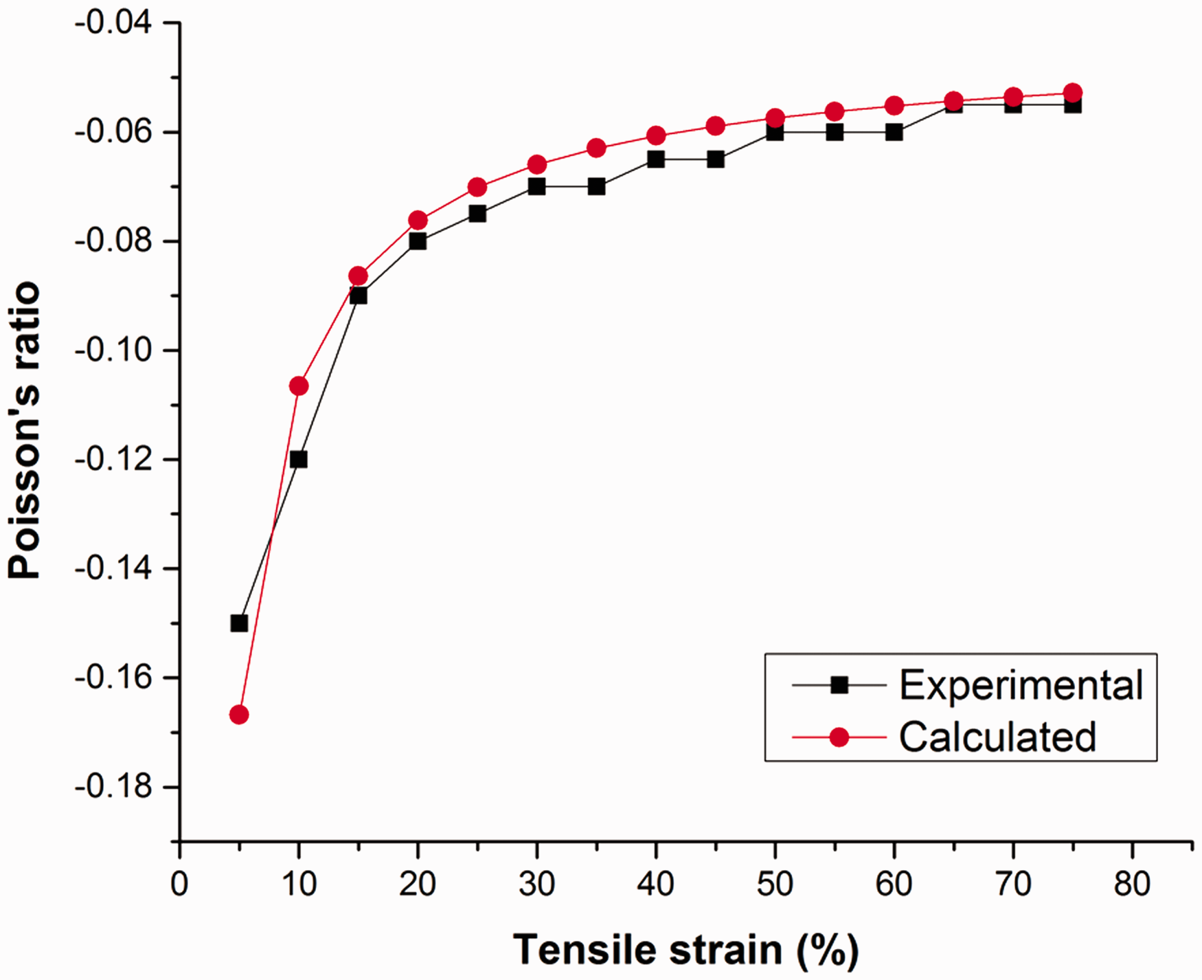
Prediction of auxetic behavior
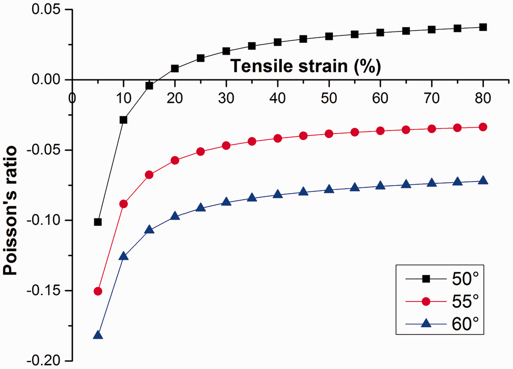
From equations (20) and (30), it can be seen that the PR of the fabric when stretched in the warp or weft direction depends on β. To study the effect of β on the PR of fabric, the PR of the fabric is calculated for different values of β and PR curves are plotted as a function of the tensile strain for different values of β using equation (20) when stretched in the warp direction and equation (30) when stretched in the weft direction. The prediction curves for both stretching directions are presented in Figures 17 and 18, respectively. It is evident from the prediction curves that when the fabric is stretched in either direction, the auxetic effect rapidly increases with an increase of β. This behavior can be explained by the fact that the larger the value of β, the less will be the shrinkage at section C. Thus, the straightening of tensile yarns will be achieved earlier, resulting in higher transposing of shrinkage even at smaller strains, which will increase the auxetic effect. Therefore, to design a bi-stretch auxetic woven fabric based on REH geometry, a higher value of β is more suitable.
Effect of β on the Poisson’s ratio of fabric when stretched in the warp direction. Effect of β on the Poisson’s ratio of fabric when stretched in the weft direction.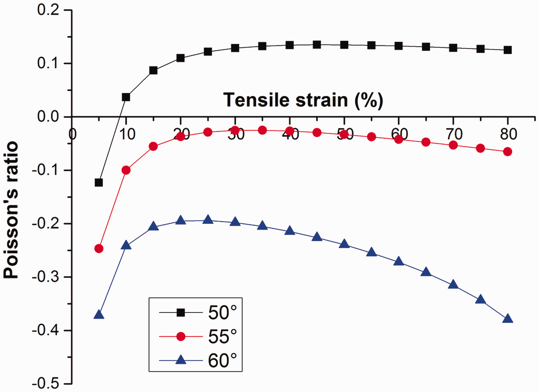
Conclusions
The bi-stretch auxetic woven fabric structure was designed and fabricated based on the REH geometry. Its deformation behavior was geometrically analyzed when the fabric was stretched in the warp and weft directions. Based on the experimental observations, a geometrical model for each stretch direction was proposed and the relationship between the PR and tensile strain was established by constructing a semi-empirical equation. The following conclusions can be drawn according to the study.
The rib segments of the REH unit cells are not kept constant under extension due to easy deformation of the fabric structure. The deformation behaviors of the fabric structure in the warp and weft directions are different; therefore, different geometrical models are required to analyze the deformation behavior in each direction. The constructed semi empirical-equations are simple and fit well with the experimental results. They could be used in the design and prediction of the auxetic behavior of bi-stretch auxetic woven fabrics made with the same type of materials and geometry but with different values of geometrical parameters. The auxetic effect of the fabric structure is greatly affected by geometrical parameters a, b, and β. While a and b have different variation trends when stretched in the warp and weft directions, an increase in β will lead to an increase of the auxetic effect of the fabric.
Declaration of conflicting interests
The authors declared no potential conflicts of interest with respect to the research, authorship, and/or publication of this article.
Funding
The authors disclosed receipt of the following financial support for the research, authorship, and/or publication of this article: This work was supported by the Research Grants Council of Hong Kong Special Administrative Region Government (Grant Number 15205514).