
Abstract
In recent years, fully fashioned flat knitting fabrics have been extensively studied owing to their superior formability, rich application range and advanced knitting technology. However, the yarn tension fluctuations during the knitting process are difficult to control. The yarn tension in the knitting process is affected by many factors, such as the carriage running speed, structure, yarn properties, clothing parameters, and so on. In this work, a tension model of the yarn was established to explore the regularity of yarn tension variation, which was caused by the running speed and direction of the carriage when producing fully fashioned fabrics. Then, a tension compensation device was set up to reduce tension fluctuations to improve the quality of fully fashioned fabrics. Results showed that the tension fluctuation in the dynamic change of the tension was reduced to a certain extent by adding the tension compensation device. Meanwhile, the average value and fluctuating standard deviation of the yarn tension between the forward and backward processes were significantly reduced during a cycle of the knitting process. This indicates that controlling the tension fluctuation in the knitting process will effectively improve the surface evenness of the fully fashioned flat knitting fabric.
Keywords
The forming process of conventional knitted clothing generally needs to go through several processes, such as garment piece knitting, looping seams, etc., which is complicated and labor-intensive. Through the cooperation of beds and needles of the flat knitting machine, the fully fashioned knitting can form changes of structure and technological design, such as cylinder knitting, adding or reducing needles knitting, local knitting and C-type open knitting, so as to produce three-dimensional structural fabric. 1 , 2 The fabric produced by the fully fashioned technology has good variability of structure, which can fit the shape better with high production efficiency. So, fully fashioned knitting has been extensively researched in the development of knitting products due to its superior formability, rich application range and advanced knitting technology.3–5 Compared with circular weft knitting and warp knitting, 6 , 7 the yarn feeding method of flat knitting has great particularity, which is attribute to the fixed position of the bobbin and the yarn feeder running with the carriage, making the yarn feeding path dynamically change during the knitting process. Therefore, positive yarn feeding is difficult to achieve. 8 , 9 The deceleration and rotation acceleration of the carriage will cause part of the yarn to remain as it drives the yarn feeders to knit, thereby increasing the fluctuation of the yarn tension of feeding. Fluctuations in the feeding tension often cause loose loops at the edge of the fabric. In particular, it makes fabric defects such as lack-paste in the ground of the plating fabric when highly elastic yarns or inelastic yarns are used, affecting the quality of the fabric. 10 , 11
Research on the tension of the yarn in the knitting process focuses on warp knitting and circular weft knitting, and there is less research on flat knitting due to the special yarn feeding method. Pohlen et al. 12 investigated how to reduce yarn tension differences in technical warp knits based on a warp yarn tension analysis on a warp knitting machine with multiaxial weft yarn insertion. A method is provided to substitute the subjective warp let-off adjustment by a model of tension control, which increased process reliability and product quality. Heravi et al. 6 researched the effects of knitted loop length on yarn fluctuation amplitude during feeding into a circular knitting machine. A new optical infrared (IR) electronic monitoring system was designed and developed in order to study the behavior of the yarn fluctuation amplitude during the feeding process. The fluctuation amplitude was evaluated by analysis of variance, and results showed that the increase of loop length would significantly reduce the yarn fluctuation amplitude. Choy et al. 13 stated that input yarn tension variation is one of the most significant factors influencing the dimensional stability of the knitted panels. A new method of yarn feeding was suggested in order to solve this problem. This method utilized storage yarn feed to eliminate the undesired effect of yarn feed speed variation and was applied as a prototype. Results showed a promising and satisfactory improvement in the fabric quality. Wang et al. 14 tested and studied the yarn tension fluctuation rules of the computerized flat knitting machine. Through the research, it was concluded that the yarn elasticity, the running speed of the carriage, the structure of the yarn and the side spring tension device were all the factors that caused the dynamic tension fluctuation of the horizontal knitting machine.
Compared to the running speed and the running direction of the carriage, the knitted structure, yarn properties and garment parameters influence the yarn tension slightly. Therefore, we choose the two factors that have a greater impact on tension fluctuations without changing other conditions, so as to achieve the purpose of scientific research and improvement on the impact of tension fluctuations. The experiment mainly focused on the influence of different knitting speeds on yarn tension in the state of cylindrical knitting, and established the basic model of the change of yarn tension. The basic model could be used to compensate for the tension at different force stages, which has a certain value for reducing the yarn tension difference and the yarn tension fluctuation. At the same time, we proposed a yarn tension compensation mechanism. By studying the fluctuation of yarn tension under the condition of tension compensation, the yarn tension was controlled to keep uniform throughout the knitting cycle. It had certain significance to improve the quality of high value-added fully fashioned knitting products.
Braiding process and yarn tension measurement
Yarn feeding path
According to the width of the fully fashioned computer flat knitting machine, there are two different feeding paths, namely top feeding and side feeding. Their feeding paths have different conveying trends, resulting in different tension changing regularity. Generally, a machine with smaller width uses the top feeding path to convey the yarn. In the process of feeding, the feeding route changes constantly with the movement of the yarn feeder, such as in the SWG061N2 two-needle-bed flat knitting machine (Shima Seiki Co., JPA.). In a fully fashioned knitting machine with a four-needle bed, side feeding is generally used as there are many yarn routes, such as in the MACH2XS153 flat knitting machine (Shima Seiki Co., JPA.). The feeding route (red route) is shown in Figure 1.
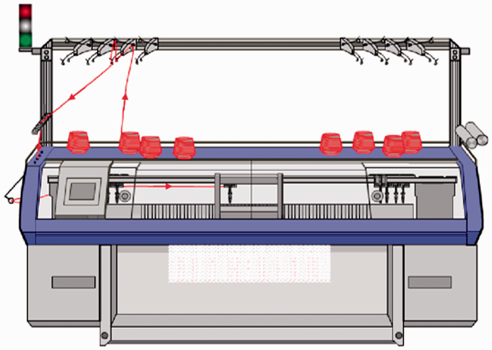
Yarn conveying system of the four-needle-bed fully fashioned knitting machine. (Color online only.)
Principle of measurement
A TS1-200-A2-CE1 three-roller tension sensor (Schmidt + Haensch Co., GER) is mainly used in yarn dynamic tension sensing tests. As shown in Figure 2, parts B and C of the tension sensor are fixed in two wheels, and Wheel A is used as the sensor contact to generate displacement under force F. The displacement signal has a certain function relation with the yarn tension T, that is T = f (F, δ), where δ represents the change of displacement. The TS1-200-A2-CE1 three-roller tension sensor with high precision and simple system structure has a maximum range of 200 cN, and is easy to operate. 13 Besides, the spindle encoder is installed on the machine to record the running situation of the carriage, which is transmitted together with the pressure sensing signal to the signal conditioning amplifier circuit board. Then, the signal is transmitted to the analysis software (LMS Test Lab) in a computer to obtain the yarn tension dynamic fluctuation curve.
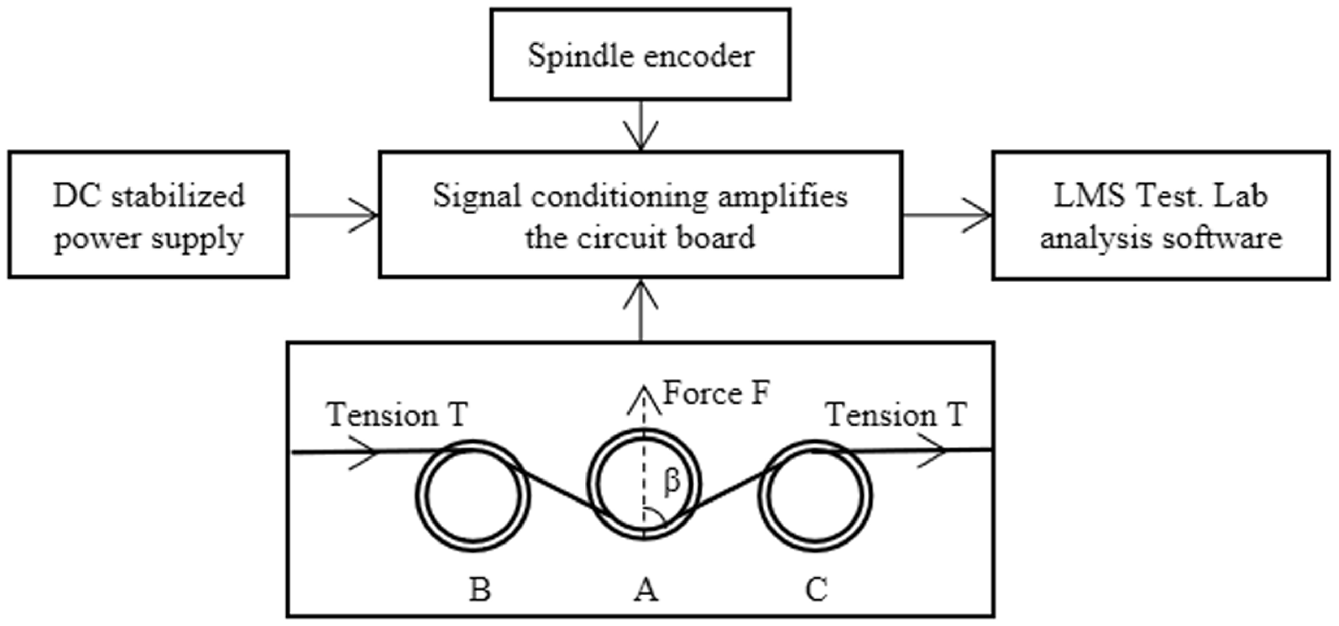
Tension sensing system. DC: direct current.
Test system construction
Taking the four-needle-bed flat knitting machine as an example, the tension measuring system is constructed by combining the tension sensing device. The three-roller tensioner is installed on the side tensioner of the flat knitting machine. As displayed in Figure 3, v is the speed of carriage, ΔL is the feeder deceleration distance ab, T0 is the feeder acceleration and deceleration stop time, S1 is the leftmost feeder stay distance ac (relative to the yarn tension point) and l is the yarn required for each loop.
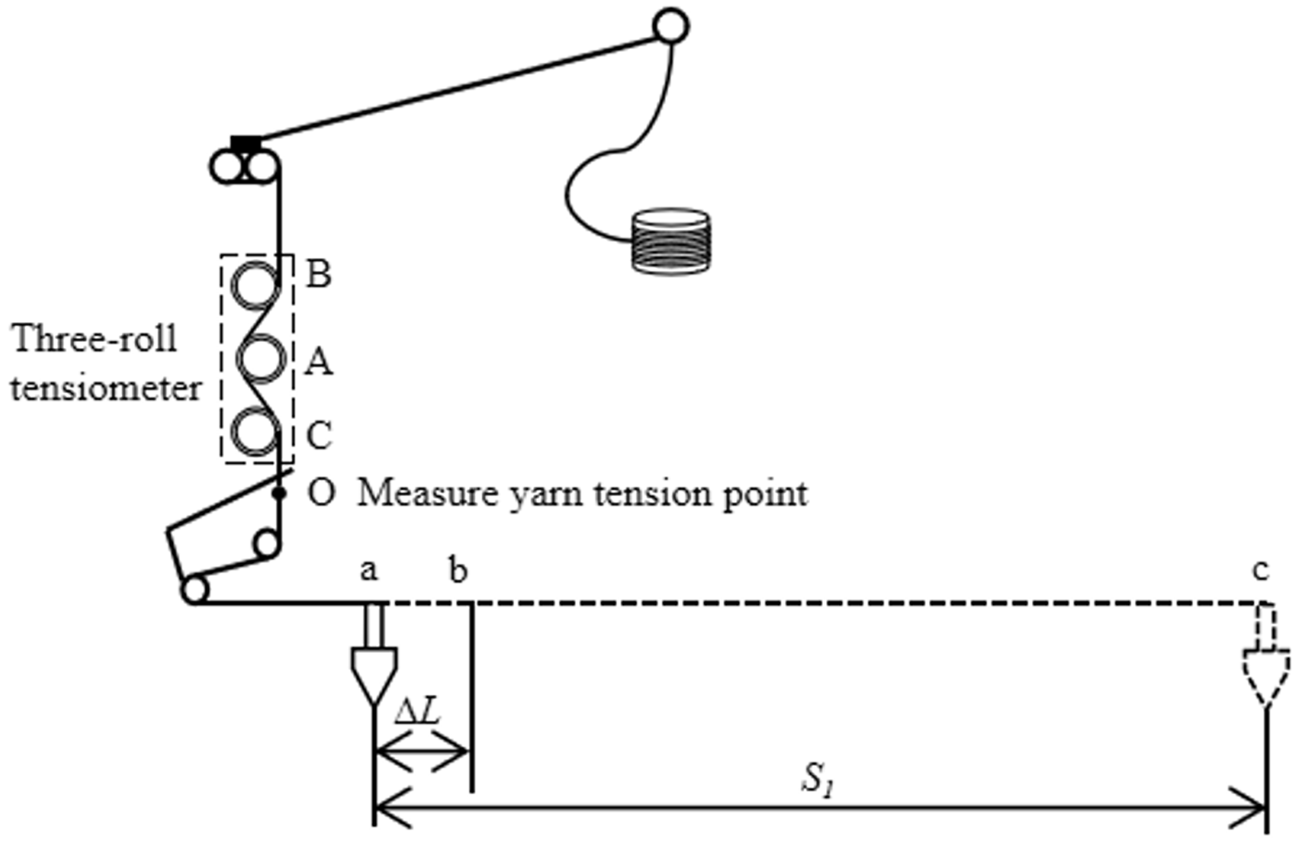
Tension testing system.
Yarn tension model during knitting
Firstly, the dynamic tension model of the yarn was established by the tension of the yarn in the knitting process of the flat knitting machine. Then the dynamic tension model was analyzed by the force of the yarn in each stage. Finally, the tension curve of the experimental tension was compared with the tension dynamic model to verify the accuracy of the model.
Real-time tension measurement
The tension sensor was installed on the four-needle-bed flat knitting machine to record the dynamic tension. The machine model is a MACH2XS153 (Shima Seiki Co., JPA), which has its own i-DSCS device to control the amount of yarn delivery of yarns by measuring the speed and tension in real time. However, in order to verify the effect of the tension compensation device, the yarn is directly passed through the side tension spring device without using the i-DSCS device. The speed of the carriage during round-trip knitting movement was set to the same values, which were 0.2, 0.4, 0.6 and 0.8 m/s, respectively. The data acquisition frequency was 32 Hz. The dynamic change curve of yarn tension in the knitting procedure under four running speeds could be obtained through LMS Test Lab analysis software processing, as shown in Figure 4.
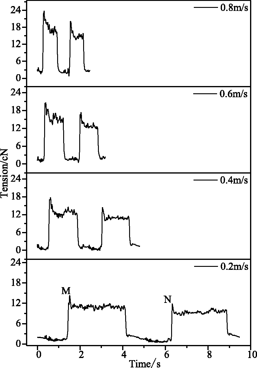
Dynamic curve of tension.
By evaluating the tension fluctuation curve in Figure 4, the regularity of yarn tension without tension compensation could be intuitively obtained. That is, the yarn tension fluctuates more in the knitting process when the carriage runs faster. It could be seen from the Figure 4 that there were two obvious changes in yarn tension (Points M and N) in the initial process of each knitting cycle, which were caused by the relaxation of yarn tension and the instability of yarn taking with the needle hook when the carriage started to drive the yarn feeder. In addition, the yarn tension always fluctuated in a small range due to the loops formed by the yarn feeding into the needle.
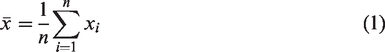
In order to evaluate the yarn tension fluctuation regularity in detail, the average value and the overall standard deviation index of the sample are introduced to quantitatively analyze the comparison of the yarn tension fluctuation amplitude in a knitting processing. Here, x1, x2, …, xn are set as the yarn tension values measured in the whole knitting procedure at each collection time, where x is the total sample and the sampling frequency is 32 Hz. Thus, the average of x and the sample standard deviation σ can be described as in Equations (1) and (2), respectively
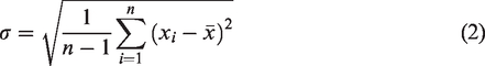
The evaluation parameters of yarn tension, such as the maximum value and sample standard deviation, are displayed in Table 1 in detail. In a cycle of the knitting process, the carriage drove the feeders to knit roundly. Herein, forward represents the process away from the side feeding device, and backward represents the process close to the side feeding device.
Evaluation parameters of yarn tension change
According to the data in Table 1, the standard deviation of the yarn's overall tension gradually increased as the running speed of the carriage rose in a measurement cycle, indicating that the tension fluctuation of the yarn increases during the whole knitting process. The average and standard deviation of the tension of forward and backward knitting go up gradually along with the growth of the speed. This phenomenon illustrates that the speed also had an influence on the tension in the loop of knitting, that is, the tension and tension fluctuation become larger with a higher speed.
Tension model analysis
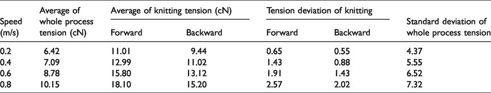
The tension of the yarn can be analyzed by the movement regularity of the yarn feeder. The tension foundation model can be divided into five parts. When the feeder started to move, the initial tension T of the yarn is the tension F1. During part 1 (O - t1), the feeder starts moving from stillness, and the tension increased sharply to F3. F3 was the sum of side tension and pulling power, that is, F3 = F1 + F2. During part 2 (t1 – t2), the carriage was knitted at a constant speed, and the tension of the needle hook on the yarn fluctuated within a small range of F3. The force of the yarn is shown in Figure 5(a). During part 3 (t2 – t3), the yarn feeder was rapidly decelerated by the friction force f when the yarn feeder completed knitting in a course, and the tension T on the yarn returns to F1. During part 4 (t3 – t4), the yarn tension increased sharply to F2 under the action of the knitting needle as the carriage rotated and drove the feeder to knit at a uniform speed. The yarn tension always fluctuated within a small range during the knitting process. The force of the yarn is shown in Figure 5(b). During part 5 (t4 – t5), when the carriage ran to the leftmost side of the cloth, the yarn feeder stopped moving by friction f. Then, the cycle of the knitting process finished.
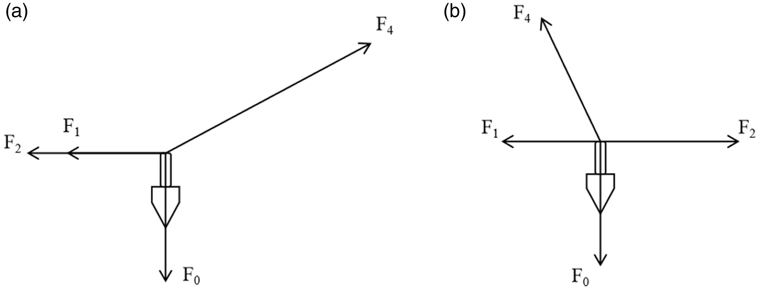
Force analysis of yarn: (a) force analysis when the feeder moved forward; (b) force analysis when the feeder moved backward. During the feeder's movement, the forces were as follows. F0 is the tension that forms the loops, F1 is the tension exerted by the side tensioner, F2 is the power exerted by the carriage’s movement and F4 is the supporting force of the feeder on the yarn.
Yarn tension model
By simplifying the variation regularity of tension in Figure 4 and analyzing the force on the yarn in Figure 5, the basic model of tension is proposed. Then, the curve of yarn tension changing is drawn before utilizing the tension compensation in the machine, as shown in Figure 6, which is in an ideal state.
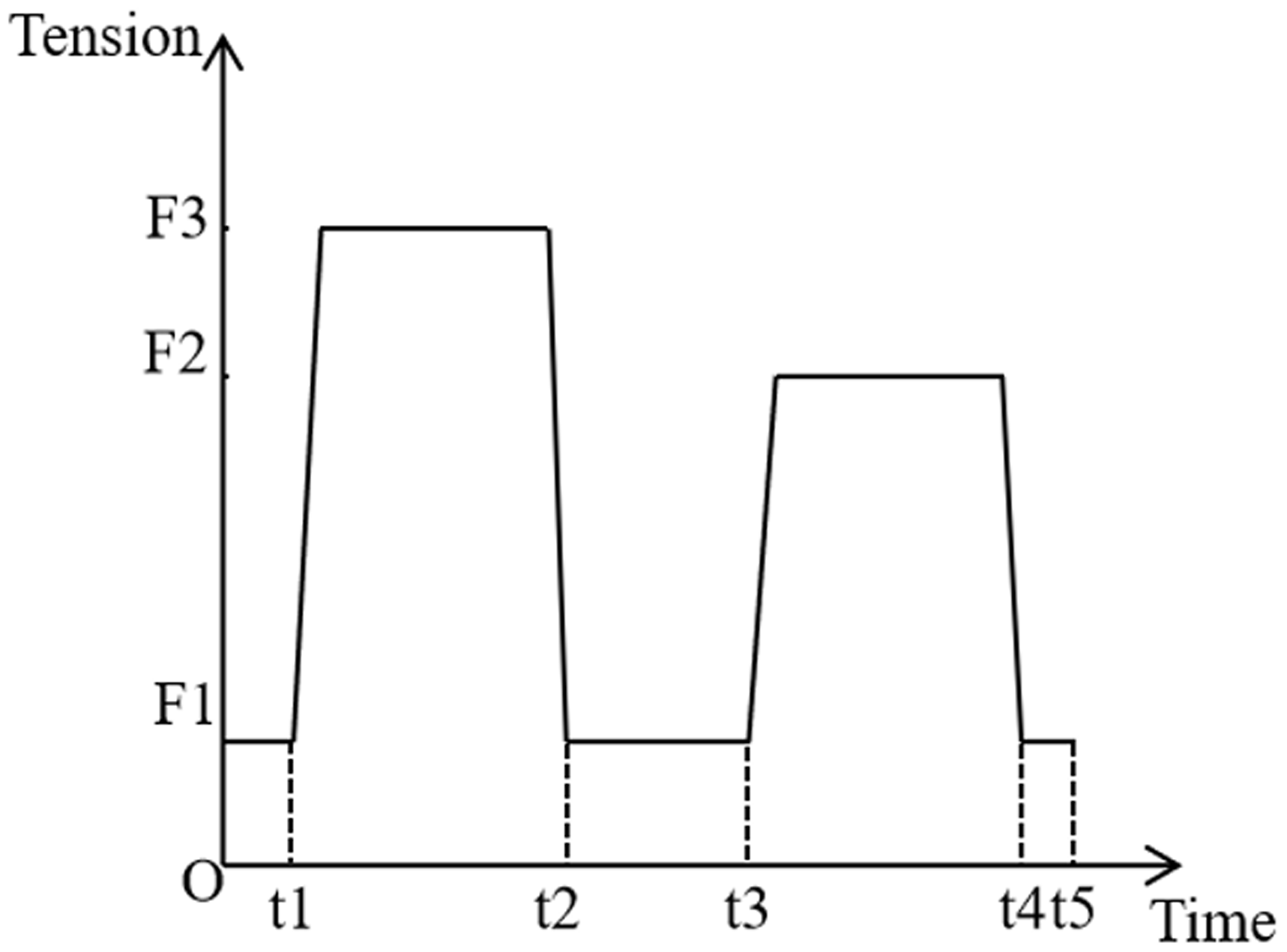
Tension foundation model.
Tension compensation
According to the yarn dynamic tension model, the tension compensation device was established to reduce the tension fluctuation in a certain extent in order to improve the fabric quality.
15
By analyzing the force process of yarn, the tension could be improved from two aspects:
balance the difference in yarn tension between the two sides of a cycle of the knitting process to achieve a uniform fabric effect; reduce the yarn tension fluctuation in a cycle of the knitting process and make the whole cloth smoother.
Tension compensation algorithm
According to the basic tension model and the motion regularity of the yarn feeder, the corresponding tension compensation model could be established to improve the yarn tension fluctuation. The yarn feeder, driven by the carriage, had four states of acceleration, uniform speed, deceleration and static in a cycle of the knitting process. Among them, acceleration to v or deceleration to a static state of the yarn feeder was completed within a very short time t0. The yarn feeder moved at a constant speed at the speed v during the time t. The feeder was stopped moving by the friction between the yarn feeder slider and the guide rail when it moved to the rightmost side of the fabric. In the backward process of the feeder rotation, the motion regularity is consistent with that of the forward process. Compared with other yarn tension studies, the principle of this tension compensation device made by ourselves is simple, and it is generally applicable to fully fashioned flat knitting machines. Besides, the tension compensation device can calculate the yarn feeding amount according to the different stages of knitting, so as to ensure the uniformity and consistency of the tension during the entire forming knitting process. Meanwhile, this tension compensation device is easy to install and can be conveniently used on other fully fashioned flat knitting machines.
The yarn required for normal operation of the carriage was divided into two processes, which are described in the following equations
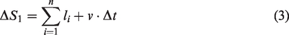
Equations (3) and (4) are for the forward and backward processes, respectively. The parameters in the equations are in Figure 3, and n is the number of loops knitting during the time of Δt. So,
Tension controller
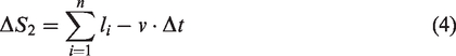
In order to verify the effect of the tension compensation device on easing tension fluctuation, a tension controller was adopted in the experiment. The yarn could be stored and transported through the yarn storage wheel. The sensor measured the pulling speed and tension of the yarn in real time to control the conveying speed of the yarn. The yarn coiling and recovery mechanism was also placed in the tension controller. Under the reciprocating mode, the yarn storage wheel could continuously coil and recover excess yarn, thus taking dynamic control of yarn tension. The controller changed the tension within milliseconds through the high-speed motor, ensuring that the yarn was always under the setting of stable feeding tension. It is suitable for flat knitting machines with reciprocating and circulating feeding yarn. The compensation process is shown in Figure 7(a).
Tension compensation system: (a) tension compensation closed-loop system; (b) system construction; (c) tension compensation device. (Color online only.)
The yarn feeder was installed above the side tension device of the MACH2XS153 four-needle-bed flat knitting machine (Shima Seiki Co., JPA). The yarn feeding path is marked with a red arrow in Figure 7(b). Device A is the tension compensation device and device B is the side tensioner of the machine. Figure 7(c) shows the structure of the tension compensation device, where 1 is the yarn guide roller, 2 is the positive yarn storage wheel, 3 is the yarn guide hook and 4 is the yarn tension tester.
Effect and evaluation of tension compensation
When the running speed of the carriage was 0.4 m/s, the yarn compensation tension was set to 1.5, 4 and 8 cN, respectively. Under the three conditions, the yarn tension fluctuation was monitored in real time. The dynamic change curve with tension compensation was obtained, as shown in Figure 8.
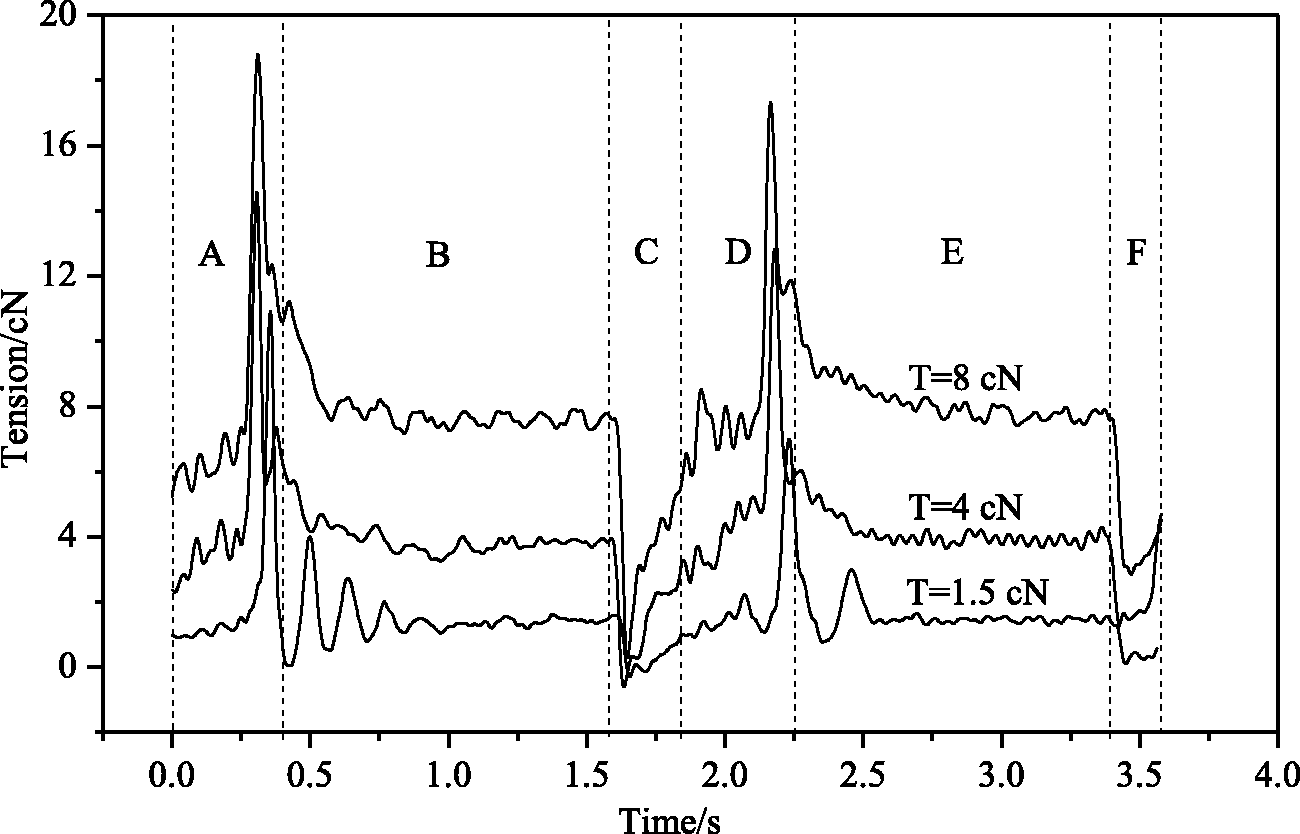
Dynamic curves with tension compensation.
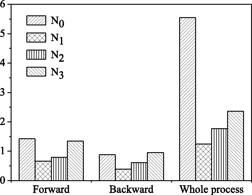
Improvement effect comparison between the forward and backward processes and the whole process of a cycle of the knitting process. N0 is the experimental result without tension compensation, N1 is the experimental result under the tension control of 1.5 cN, N2 is the experimental result under the tension control of 4 cN and N3 is the experimental result under the tension control of 8 cN.
The six phases of a cycle of the knitting process are clearly illustrated in Figure 8. In stage A, the feeder was driven to accelerate when the carriage started to move. A tension peak occurred as the yarn was thrown out of control when the carriage drove the feeder to start moving, resulting in a sudden change in tension. Subsequently, the setting tension was gradually recovered when the yarn was controlled in the knitting needles. In stage B, the yarn was knitted after being fed into the needle. The yarn tension always fluctuated within a small amplitude change, owing to the effect of forming loops. Stage C refers to the moment when the carriage reached the edge of the fabric and the yarn feeder decelerated and stopped knitting. The yarn lost control, causing the tension to be decreased instantaneously. Then, the tension gradually recovered due to the coordination between the adjustment tension control device and the side tension spring.
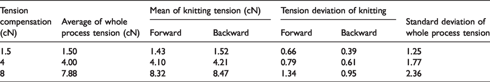
Stage A to stage C refers to the forward process of the knitting, and the backward process was similar. However, the tension of the yarn in the backward process was smaller than that in the forward process, causing the tension fluctuation to be slightly smaller. Through quantitative analysis and calculation, the compensated yarn tension variation parameters could be obtained, as shown in Table 2.
Evaluation parameters of yarn tension change after tension compensation
By comparing the yarn tension under the speed of 0.4m/s between Table 1 and Table 2, the improvement effect of the knitting process could be shown in Figure 9. When the knitting speed was fixed, different tensions could be set through the tension compensation device, which could alleviate the overall tension fluctuation to a certain extent. At the same time, the yarn tension could be controlled within the setting tension range during the forward and backward knitting processes. Compared with the situation without tension compensation, the difference between the average tension of the forward and backward processes is greatly reduced. The change was reflected in the fabric surface. The front piece of the cylinder cloth without the tension compensation device was slightly longer than the back piece, and the compensation could make the front piece and the back piece have the same length. This improvement effect is more obvious on plating fabrics with elastic yarns. The fabric shown in Figure 10(a) can clearly be seen with many barre marks, which are caused by the uneven tension of the elastic yarn during the knitting process. Figure 10(b) displays the fabric after adding a tension compensation device on the fully fashioned flat knitting machine, where the fabric quality has been significantly improved. Under the same process, the cloth piece was more uniform and denser. Obviously, the quality of fabric was improved after compensating.
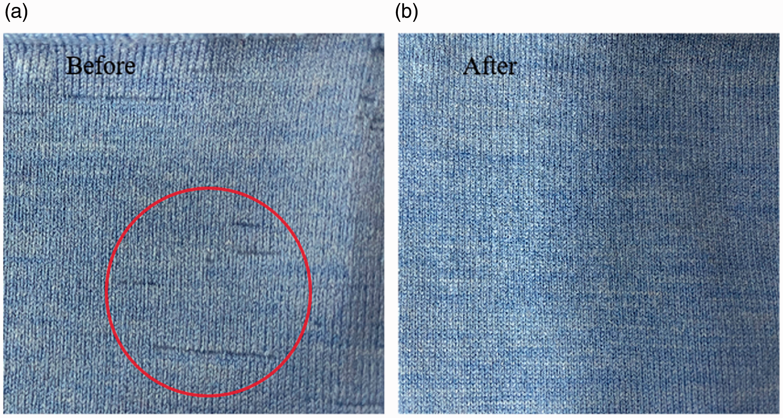
Comparison of fabric quality before and after improving the tension fluctuation: (a) the effect of plating fabric without a positive yarn feeding device; (b) the effect of plating fabric after a tension compensation device was added to the flat knitting machine.
Conclusions
In this paper, the basic tension model of the yarn was established through the study of the yarn feeder movement, and the tension of the yarn during the knitting process was analyzed in detail. Results showed that in a cycle of the knitting process, the position with the most drastic change in the tension curve was located in the rotary acceleration position of the carriage, which tends to cause the edge loops to relax. By controlling the feeding amount of the yarn, a certain length of yarn could be recovered appropriately when the carriage was turning around, while a certain length of yarn was released during acceleration. After adding the tension compensation device designed originally, the yarn could be curled and relaxed according to the feeding speed in real time. Such a device is used to control the tension fluctuations, which can reduce the peaks and valleys of the tension fluctuations and the tension difference during the reciprocating movement of the machine carriage. In a cycle of the knitting process, the standard deviation of the overall tension fluctuation was significantly reduced. Meanwhile, the difference of the average value of the tension and the standard deviation of the fluctuation between the forward and backward processes were reduced to a certain extent. It was proved that the tension compensation device could improve the fabric quality effectively.
Footnotes
Declaration of conflicting interests
The authors declared no potential conflicts of interest with respect to the research, authorship, and/or publication of this article.
Funding
The authors disclosed receipt of the following financial support for the research, authorship and/or publication of this article: This work was supported by the Fundamental Research Funds for the Central Universities (Grant No. JUSRP52013B) and the National Science Foundation of China (Grant No. 61902150).