
Abstract
Compact spinning, as a new kind of spinning technology, has gained wide attention because of its great reduction in spinning triangle and yarn hairiness. In order to meet the demand of high-grade clothing, research on further improving the performance of compact spun yarn is the emphasis. Of all the existing compact spinning systems, the four-roller compact spinning with lattice apron is most widely used at present because of its low cost. Therefore, this paper aims to put forward a new kind of device to improve yarn performance for four-roller compact spinning systems. Related experiments have been done to verify the efficiency of the device, and the mechanism is analyzed by computational fluid dynamics. The numerical simulation shows that the device can change the direction of airflow and increase the velocity in the directions of transverse condensing and thickness. It is shown that the air damper is convenient to use and has potential applications in spinning compact yarns with better performance.
Compact spinning is a new kind of spinning method developed on the basis of ring spinning. By adding a fiber-converging device on the established ring-spinning frame, fiber bundles are straightened and most of the fibers at the ends can be rolled in the yarn, so that the spinning triangle is reduced significantly. Compact spinning can be divided into pneumatic condensing and mechanical condensing, according to the condensing principle. 1 At present there are five kinds of compact spinning system, four of which are pneumatic condensing, occupying the leading location on the market.2–4 Therefore, research focusing on the pneumatic compact spinning system has become a popular issue. As a type of yarn suitable for high-grade textiles, the performance of compact spun yarn is particularly important. Compared with the ring spun yarn, the harmful hairiness (over 3 mm) of compact spun yarn is reduced by 70–80%, while the breaking strength is increased by about 10%.5–7 The hairiness is essential for the yarns because it affects not only the appearance of the yarns, but also the quality of subsequent products.8–10 Besides this, the high breaking strength of the yarn increases the strength and fastness of the fabric. In addition, reducing the coefficient of variation of breaking strength can reduce breakage during the weaving process and increase production efficiency. So it is crucial to improve the yarn performance by upgrading the existing equipment.
There has been some research focusing on the upgrading of equipment. Su and his team put forward three kinds of guiding device for the compact spinning system with a perforated drum. 1 Liu and his team developed another kind of guiding device for a four-roller compact spinning system. 3 The optimal installation height of the guiding device in their studies was dependent on the yarn number. In actual production, it was not beneficial for continuous production. To the best of our knowledge, there are few studies about improving equipment, except for those mentioned above.
Four-roller compact spinning with a lattice apron is most widely used for its advantages of maintenance and price. 11 In this study, a new air damper was developed to improve yarn performance for the four-roller compact spinning system, which is convenient to use and has a wide range of applications. The effectiveness of the device was verified by the experiment and the numerical simulation.
Experimental
Equipment improvement
The schematic of the improved four-roller lattice apron-type compact spinning system is shown in Figure 1.
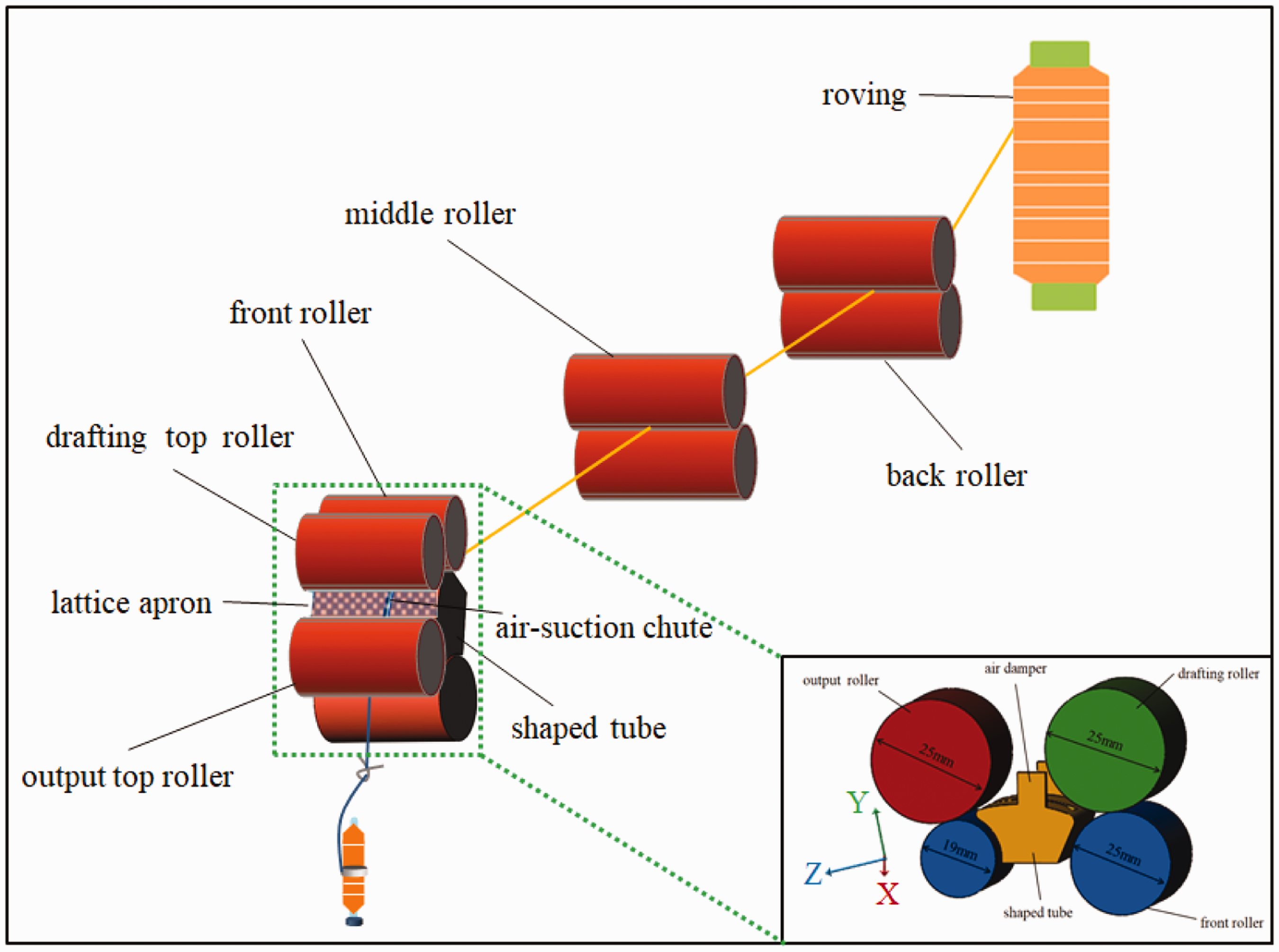
The schematic of the four-roller lattice apron-type compact spinning system with an air damper.
The air damper was set as a rectangle and located on both sides of the fiber-converging zone, without any contact or friction with the lattice apron or drafting roller. The air damper was fixed to the shaped tube, which was 1 mm away from the drafting top roller in the horizontal direction and 10 mm away from the center of the drafting top roller in the vertical direction. The length of the air damper in the direction of fiber output was 7.8 mm and the width was 7.1 mm, which was consistent with the direction of fiber thickness. The thickness of the air damper was 0.7 mm and it was made of flexible material. The lower right corner of Figure 1 shows the details of the shaped tube and location of the air damper.
In order to confirm the influence of the air damper on the yarn performance, different yarns with the fineness of 14.7 tex and 17.2 tex were spun by the original system and the system with an air damper, respectively. The spinning process is shown Figure 2.
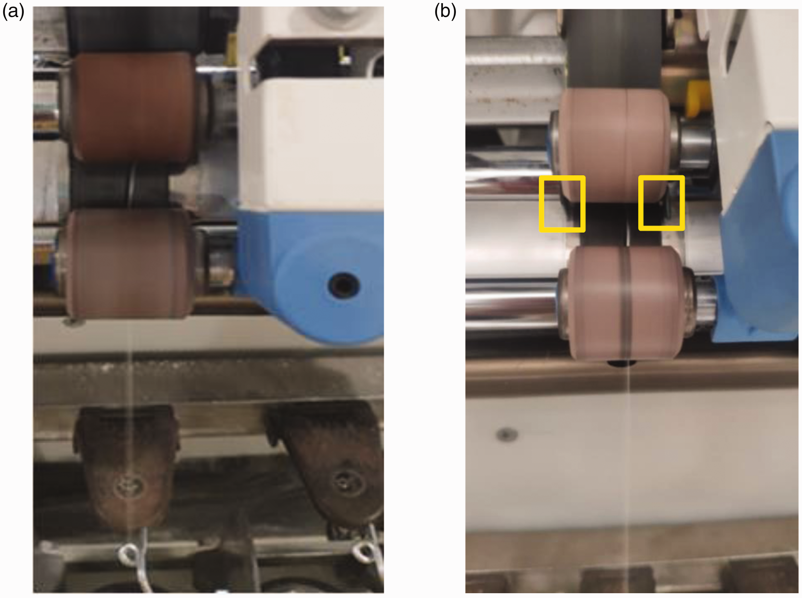
The compact spinning system: (a) the original compact spinning system; (b) the compact spinning system with an air damper.
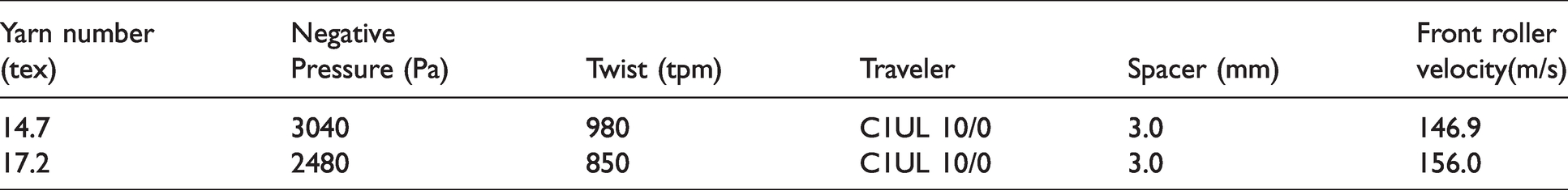
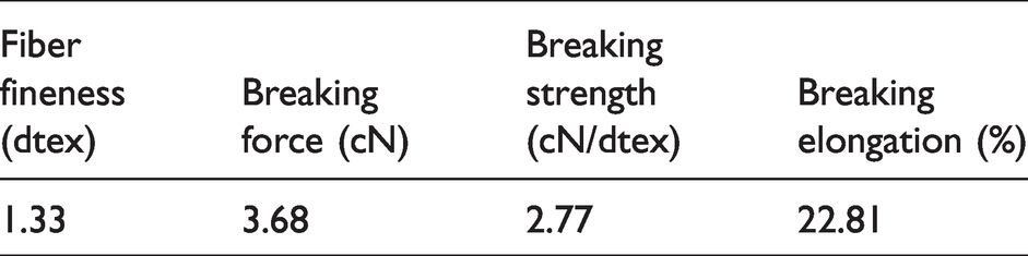
The spinning parameters are shown in Table 1. Both of the yarns were made of viscose fibers. The parameters of the viscose fibers are shown in Table 2.
The spinning parameters of the yarns with different yarn counts
The parameters of the viscose fibers
Testing methods for yarn performance
The breaking strength of the yarns was measured by a YG063 fully-automatic single yarn strength tester with a pre-tension of 0.5 cN/tex at a speed of 500 mm/min. The interval of the samples was 1 m and the maximum breaking elongation was 20%. In order to ensure the validity of the results, the yarns that broke at the ends of the clamps were discarded.
The hairiness was measured by a YG172A yarn hairiness tester. The length of each test was 10 m, and the speed of the tester was set as 30 m/min.
The yarn evenness was tested by a CT3000 evenness tester at a speed of 400 m/min. As the yarns were spun by staple fibers, the unevenness curve range was set as ± 100%. Before the measurements, all the samples were humidified for 48 hours with a relative humidity of 65 ± 2% and a temperature of 20 ± 2°C (standard atmosphere conditions).
Numerical simulation of the condensing zone
Numerical simulation was adopted to observe the velocity and distribution of airflow of the four-roller lattice apron-type compact spinning system with and without an air damper. A three-dimensional physical model of the condensing zone with an air damper was obtained using the software SolidWorks. The parameters of the condensing region are shown in the lower right corner of Figure 1. The airflow distribution and velocity on two surfaces were simulated by the computational fluid dynamics software ANSYS to determine the effect of the air damper. One surface was set in the condensing zone to analyze the velocity around the outlet, parallel to the plane of the Y-Z axis, and the coordinate value on the X-axis was set as 7.2. Another surface was set in the plane of the summit of the shaped tube to observe the velocity in the direction of transverse condensing.
In the simulation, the airflow was treated as incompressible gas, in other words, the airflow density was constant. According to the previous research, the Reynolds number of the compact spinning system was calculated and the value was much larger than 2300, so the state of the fluid was turbulent.12–13 As a turbulent model, the realizable
The realizable 
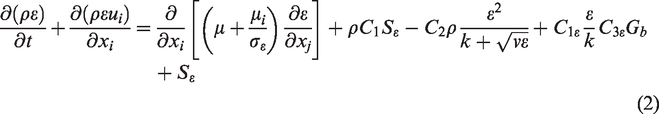
In these equations,
The constant numbers were shown as follows:

These constants were derived from experience, including the basic turbulence of the air and water. 15
The parameters were set to calculate the velocity of airflow and pressure for the whole model and the mesh was generated with an unstructured method. According to the previous study,
16
the following assumptions were adopted for the simulation:
The fibers were ignored due to their much smaller volume than the condensing zone. The lattice apron was ignored in order to facilitate the meshing and simplify the calculation.
The parameters of the boundary conditions for the flow field were set as follows:
For the boundary condition, the base value of pressure was set as 101,325 Pa. Inlet: the inlet pressure was set as 0 Pa. Outlet: the outlet pressure was set as -3000 Pa, measured by a DP2000 anemometer. Wall: other surface shear conditions were set as non-slip. Arithmetic: the steady-state implicit solver and SIMPLE arithmetic were used in the calculation model. Viscosity coefficient: the value of viscosity coefficient was set as 1.5*10−5 m2/s.
The condensing zone with an irregular shape was carried out in a cuboid using a Boolean operation. The cuboid had a length of 38 mm, a width of 30 mm, and a height of 27.6 mm. The condensing zone was subtracted from the cuboid and then the airflow area for the subsequent simulation was obtained. The condensing zone was shown in the lower right corner of Figure 1. The meshing was done by an internal program named MESH in Fluent and the grid was unstructured with a tetrahedral structure. The boundary layer of the mesh was set in the Inflation and the number of cells was 588,753 for the original compact spinning system and 590,205 for the compact spinning system with an air damper.
To show the change of the airflow velocity in the condensing zone clearly, it is necessary to set a line during the post-processing of the numerical simulation. In this study, line 1 was set as shown in Figure 3. During the simulation of the fiber trajectory, the condensing zone of the four-roller compact spinning system was divided into the rapid condensing zone, the adjustive condensing region, and the steady condensing region, 12 and line 1 was located in the adjustive condensing region, which had a great influence on the yarn performance. It paralleled the X-axis and clung to the surface of the air-suction chute. The coordinate value of line 1 on the Z-axis was -2.86 and it was 0.2 mm from the surface of the air-suction chute.
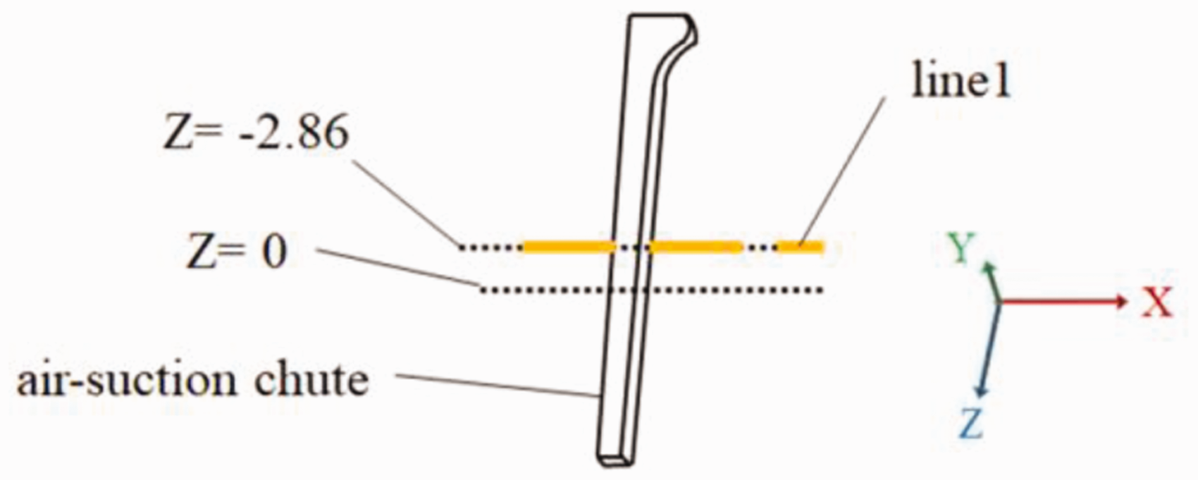
Line 1 and the air-suction chute.
Results and discussion
For the four-roller compact spinning system, the yarn performance is positively correlated with the velocity of airflow in the condensing zone. In Lian’s research, 17 the influence of the indoor partition on the air distribution was studied. The results showed that, when the partition was on the side of the outlet, the airflow distribution would be improved, and the airflow would be more uniform. Motived by this study, a series of air dampers with different lengths and widths were put forward. Among them was the optimal air damper, with a height of 7.8 mm in the direction of the fiber output, a width of 7.1 mm consistent with the direction of fiber thickness, and a thickness of 0.7 mm.
Testing results of yarn performance
The stress-strain curves are shown in Figure 4.
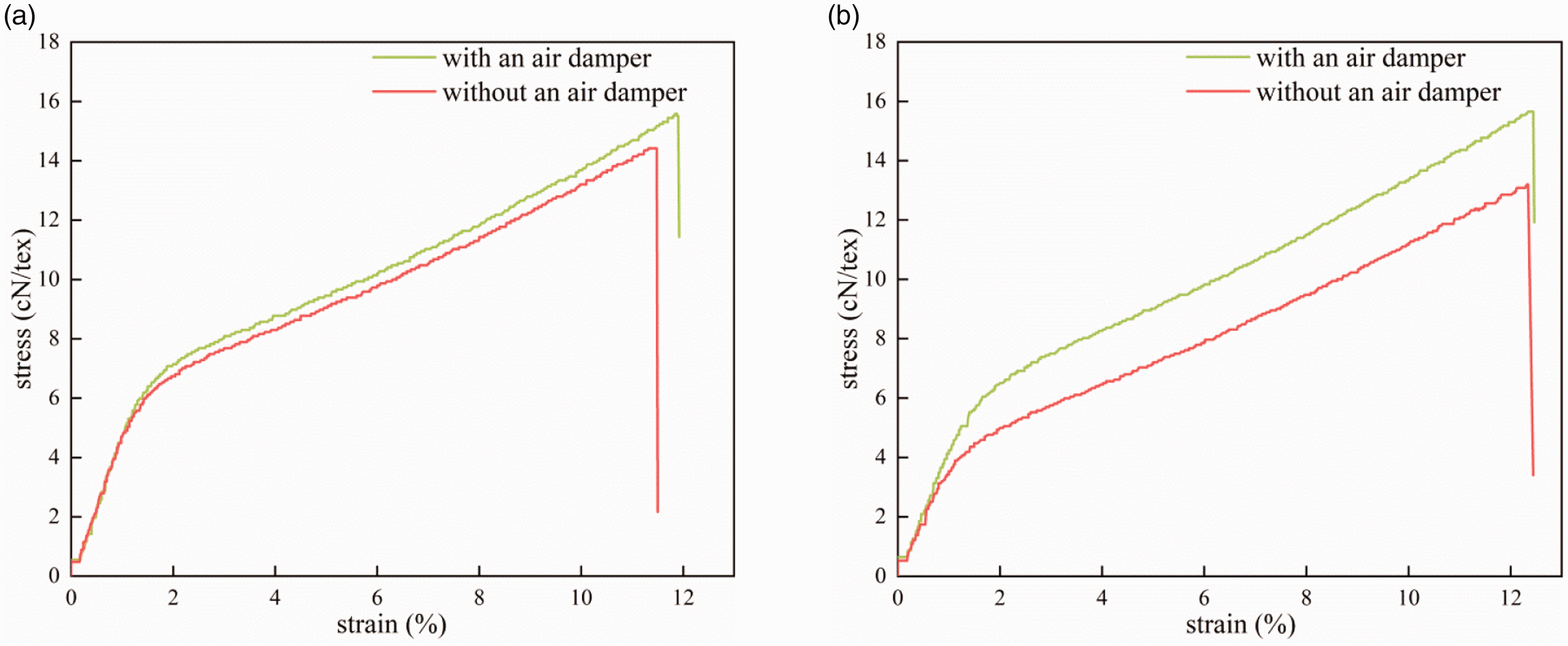
The stress-strain curve of yarns: (a) with a count of 14.7 tex; (b) with a count of 17.2 tex.
It was observed that the initial modulus of the yarns were almost the same, which meant the yarns had a similar softness. For the 14.7 tex and 17.2 tex yarns, the stress and strain of the yarns spun with an air damper were larger than the yarns spun without an air damper, so the increase of the yarn performance was most likely caused by the air damper. According to the previous research, 17 the proper location of objects would increase the airflow and make it more uniform. Based on this, we extrapolated that, with the air damper, the distribution of airflow in the condensing zone was changed and the airflow was more uniform. Therefore, the performance of yarns spun with an air damper was better than the yarns spun with the original system.
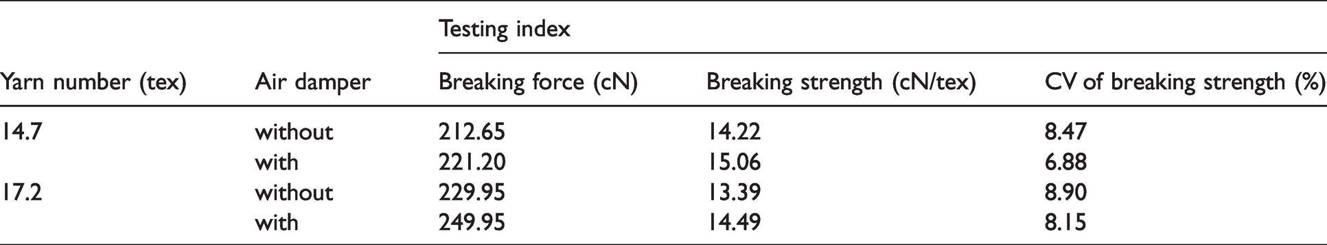
The results of the tensile properties are shown in Table 3, where we can see that the performance of the yarns spun with an air damper was better than that of the yarns spun without an air damper. For the 14.7 tex yarn, the breaking strength increased by 5.91% and the CV of the breaking strength dropped by 18.77%. For the 17.2 tex yarn, the breaking strength increased by 8.21% and the CV of the breaking strength dropped by 8.43%.
The breaking strength and evenness of yarn
The stereomicroscope photos of the hairiness are shown in Figure 5.
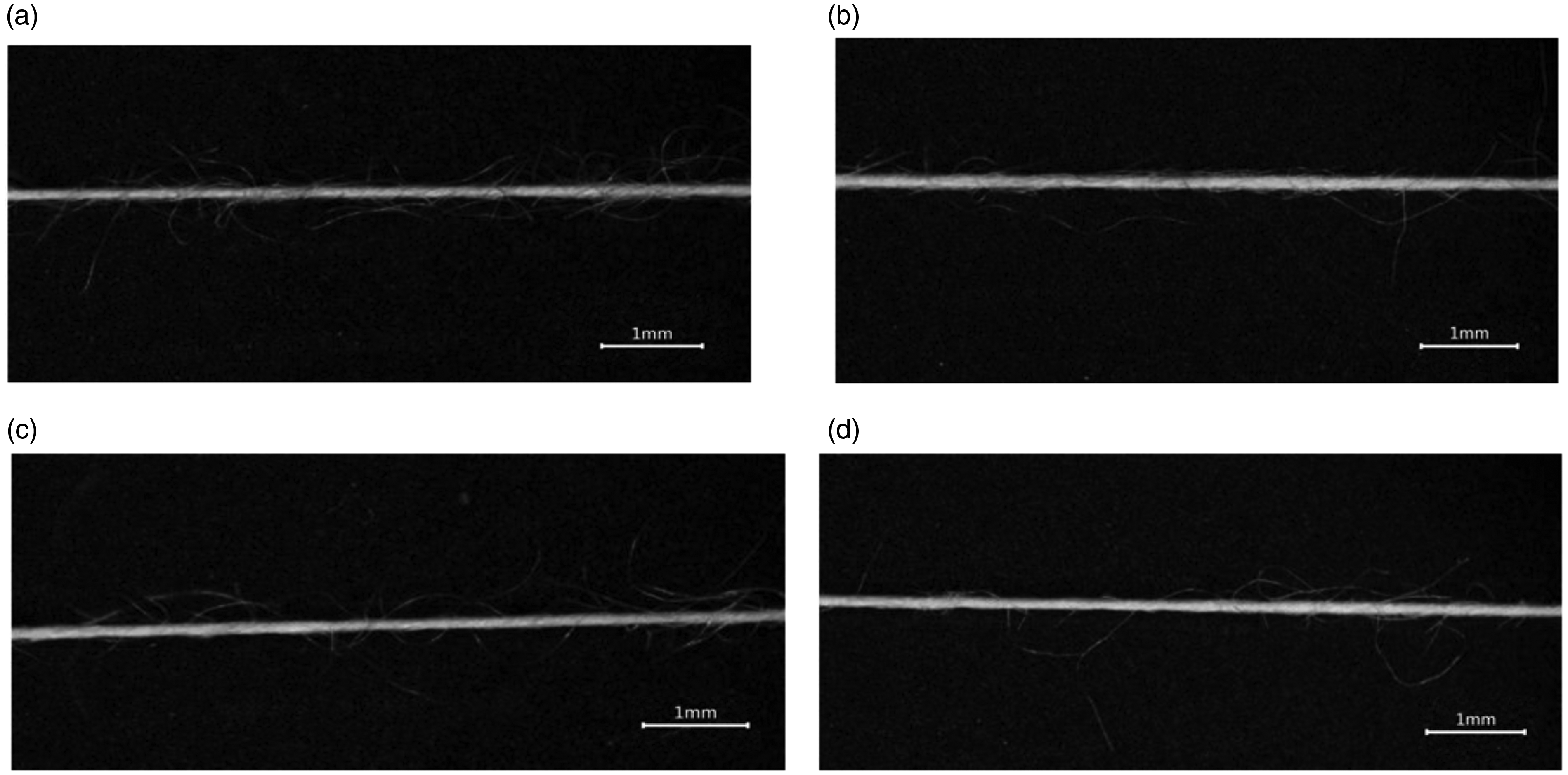
The stereomicroscope photos of the hairiness for different yarns (Magnification 20 times): (a) 14.7 tex yarn spun without an air damper; (b) 14.7 tex yarn spun with an air damper; (c) 17.2 tex yarn spun without an air damper; (d) 17.2 tex yarn spun with an air damper.
Comparing Figure 5(a) and 5(b), it is observed that the 14.7 tex yarn spun with an air damper had less hairiness. Besides this, according to Figure 5(c) and 5(d), it reveals that the 17.2 tex yarn spun with an air damper also had less hairiness. Therefore, the air damper can improve the yarn hairiness.
The results of hairiness and evenness of the yarns are shown in Table 4. It shows that the evenness of yarns spun with an air damper was improved, and the harmful hairiness was reduced as well. For the 14.7 tex yarn, the harmful hairiness was reduced by 11.37% and for the 17.2 tex yarn the harmful hairiness was reduced by 5.03%, which are consistent with the results in Figure 5. The unevenness of the 14.7 tex yarn spun without an air damper changed a little compared with the yarn spun with an air damper, and compared with the yarn spun without an air damper, the unevenness of the 17.2 tex yarn spun with an air damper was reduced by 4.6%.
The hairiness and evenness of the yarns
Based on the above results, the air damper indeed improved the performance of the fine count yarns. To analyze the influence of the air damper on airflow distribution and velocity in the condensing zone, the numerical simulation was carried out.
Simulation results of the condensing zone
According to the research,18–22 the yarn performance is positively correlated with the velocity of airflow in the condensing zone. The instruments, including a hot-wire anemometer, ultrasonic flow meter, laser Doppler anemometer, and trace flow meter, are commonly used to measure the velocity of airflow. However, limited by the narrow width of the air-suction chute, these instruments cannot measure the velocity components accurately. As a result, in this paper the numerical simulation was adopted to analyze the velocity of the system with and without an air damper.
The numerical simulation results of the airflow velocity in the two surfaces and line 1 are shown in Figures 6–9. The X-axis, Y-axis, and Z-axis represent the transverse condensing, thickness, and output direction of the fiber bundle, respectively. The positive and negative values represent the velocity directions, followed by the positive and negative directions of the coordinate values.
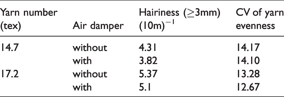
The vector diagrams of flow velocity in the X-Z section: (a) without an air damper; (b) with an air damper.
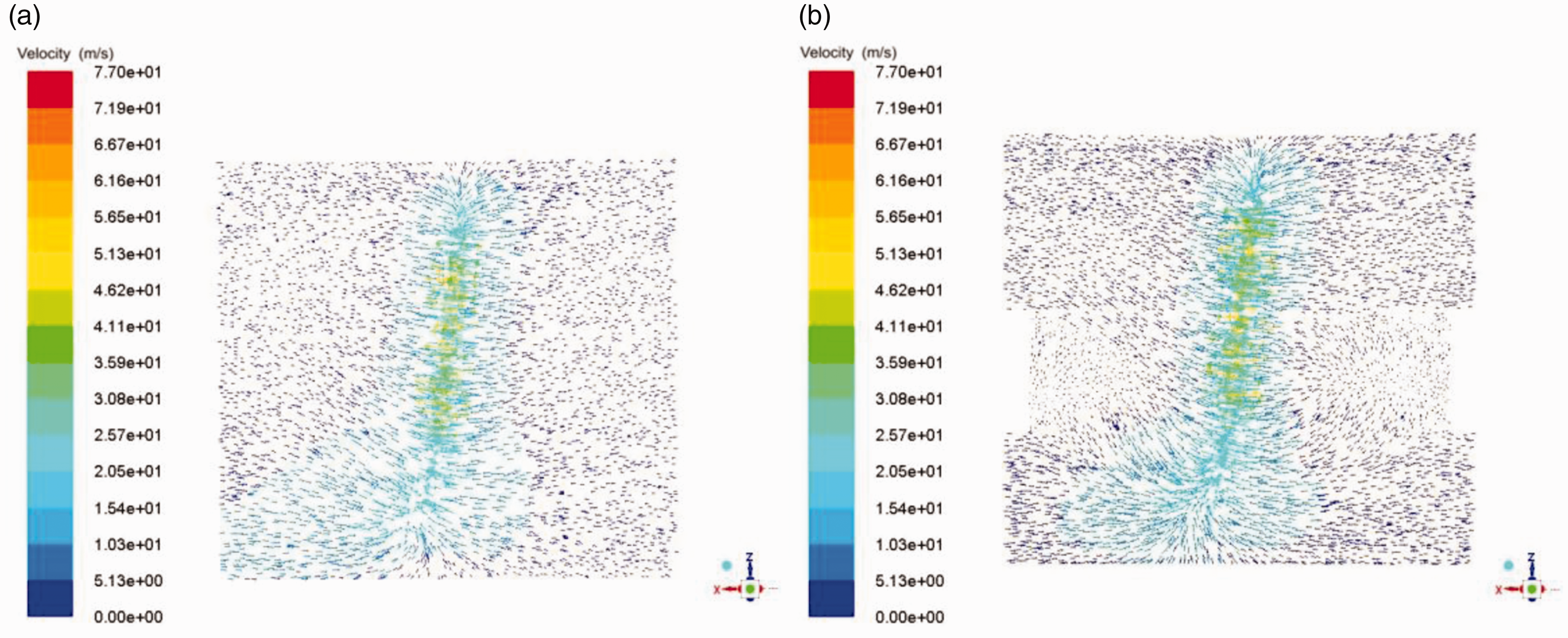
The vector diagrams of flow velocity in the Y-Z section: (a) without an air damper; (b) with an air damper.
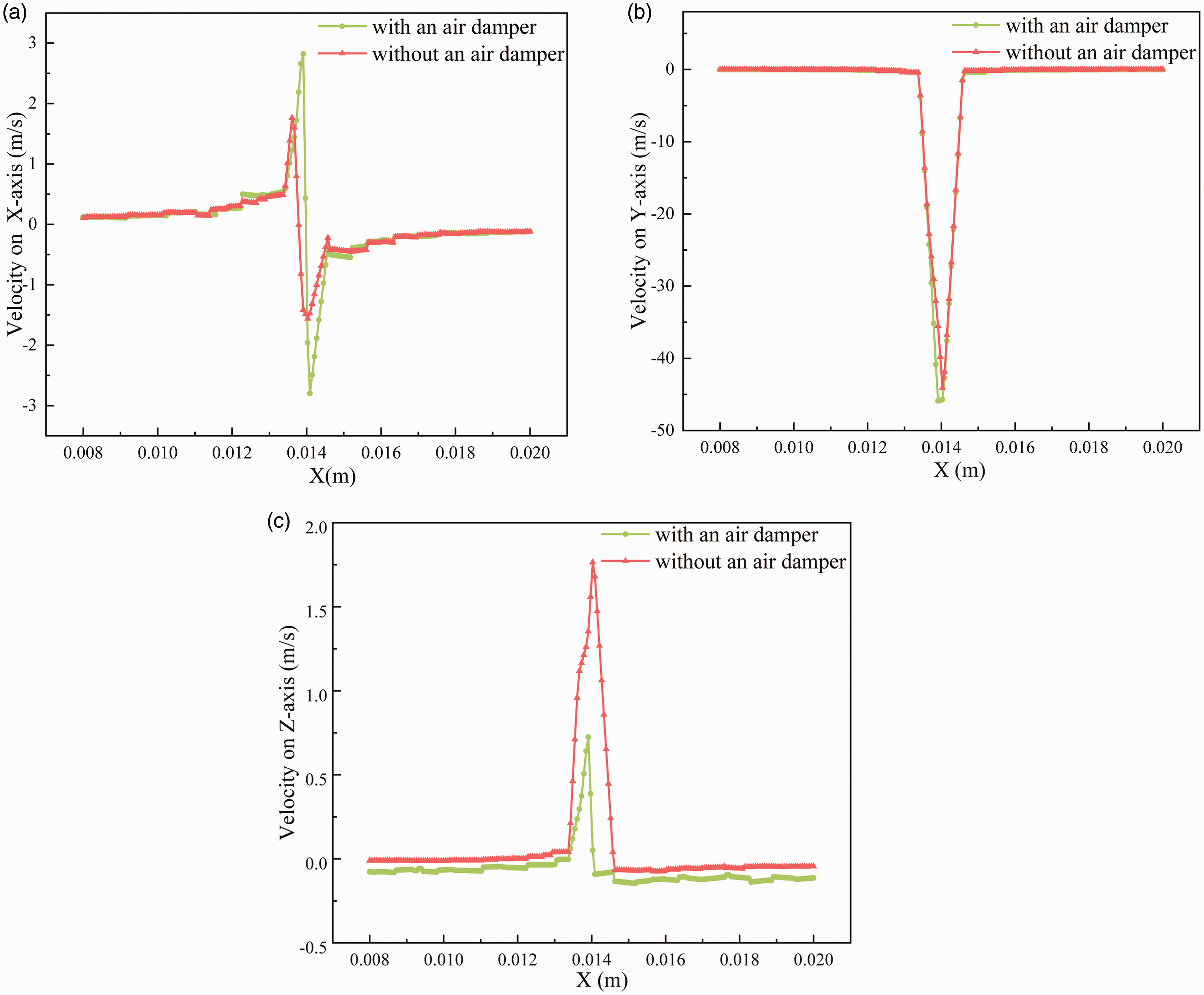
The graphs of airflow velocity above line 1: (a) the transverse condensing direction of fibers (X-axis direction); (b) the thickness direction of fibers (Y-axis direction); (c) the output direction of fibers (Z-axis direction).
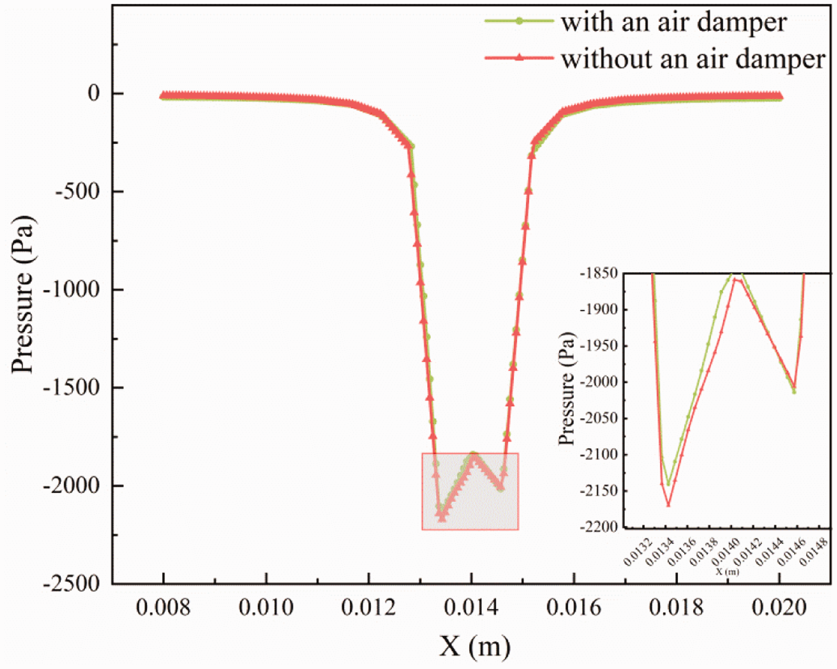
The graph of pressure above line 1.
The vector diagrams of the velocity for the system with and without an air damper in the X-Z section are shown in Figure 6. The numerical ranges were set the same for both figures to ensure the comparability of the results. It is observed that the velocity above the center of the air-suction chute with an air damper was higher than that without an air damper. With the air damper, the airflow was more concentrated around the air-suction chute and the velocity on both sides of the air-suction chute tended toward the center. So when the fiber passed through the air-suction chute, the airflow was beneficial to condense the fibers, leading to the reduction of the spinning triangle and the improvement of the yarn performance. It was consistent with the experimental results.
The vector diagrams of the velocity in the Y-Z section are shown in Figure 7. From the figure, it is observed that the velocity of the system with an air damper was higher. When it was closer to the air-suction chute, the velocity of the system with an air damper was higher, indicating that the force added on the fiber near the surface of the air-suction was the largest. In addition, with an air damper, the velocity near the front roller nip was higher, keeping the fibers attached to the lattice apron more tightly. The improvement of the velocity in the direction of thickness was helpful to control the fiber, playing an auxiliary role in transverse condensing, so as to improve the yarn performance.
The condensing effect of the compact spinning is mainly affected by the velocity component in the transverse condensing direction. The increase of air velocity in this direction indicates that the utilization of negative pressure is improved. The hodographs of the airflow velocity component in the X-axis (the transverse condensing direction) are shown in Figure 8(a).
Line 1 was 0.2 mm from the surface of the air-suction chute and it is observed that the velocity far away from the air-suction chute was low. When it was closer to the air-suction chute, the velocity was higher. The velocity reached maximum at the edge of the air-suction chute. The velocity was symmetric, and the absolute value of airflow velocity reached a minimum at the center (x = 0.0137 m). The fibers were concentrated at the middle of the air-suction chute by the transverse force, so the velocity at the air-suction chute was the key factor for the yarn spinning.
Compared with the system without an air damper, the airflow velocity of the air-suction chute for the system with an air damper was better, which was increased to 3 m/s. The velocity was more stable and concentrated around the air-suction chute, which was consistent with the result shown in Figure 6. The increase of the airflow velocity led to the strands of fibers being fixed well in the middle of the air-suction chute during the spinning process and narrowed down the width of the fiber bundles. The ends of the fibers also wrapped into the major structure of the fiber bundles easily and improved the yarn hairiness. The fluctuation of the system with an air damper was smaller than without an air damper, so the air velocity was more uniform, and the condensing process of the fiber bundles was more stable without any mutation. This would improve the friction area between fibers and increase yarn breaking strength.
The airflow velocity component in the Y-axis (thickness direction of fibers) is shown in Figure 8(b). For the compact spinning system with an air damper, the airflow velocity in the Y-axis was higher than without an air damper. The air velocity reached the maximum (about 45.8 m/s) at the center of the air-suction chute, which was about 5% higher than that of the traditional system (about 43.6 m/s). With the increase of velocity, fibers were attached to the surface of the lattice apron more tightly and steadily without slipping or floating, which prevented the fiber from dispersing, so that the evenness of yarn would be better.
As shown in Figure 8(c), in the Z-axis (the direction of output), the velocity for the compact spinning system with an air damper was a little lower than without an air damper. With the decrease of velocity, the time that the fiber bundle passed through the condensing zone was prolonged, leading to the enhancement of the condensing effect and the improvement of the yarn breaking strength. In addition, since the velocity of the system with an air damper was lower in the output direction, the conveying speed of the fiber bundle was more consistent with the velocity of the front roller. This would avoid excessive drafting of the fiber bundle and increase the yarn evenness. Also, for the improved compact spinning system, the guiding force of the front clamps on the floating fibers was less than the controlling force of the rear clamps on the floating fibers in the yarn, which would control the fiber completely during the spinning process and improve the yarn hairiness.
Figure 9 shows the static pressure of the system with and without an air damper. Static pressure refers to the pressure energy of fluid. From the figure, we can see that the static pressure of the system with an air damper was different from that of the traditional one. The values of the static pressure for the system with and without an air damper were almost the same. When the airflow was in contact with the air-suction chute, viscous and friction force were formed and the mechanical energy was dissipated, so the static pressure reached the maximum at the center of the air-suction chute, which made the fiber condense at the center of the air-suction chute and consequently decrease the spinning triangle. According to the Bernoulli equation, the sum of the kinetic energy and static energy was the same for the condensing zone, both with and without an air damper, which was consistent with the results of static pressure. This reveals that the utilization of static pressure could be improved by using the air damper, which was beneficial for the fiber condensing and yarn performance.
Conclusions
In this study, a new kind of air damper was put forward to improve the traditional compact spinning device. The results of the test proved that this improvement could enhance the yarn breaking strength and reduce the harmful hairiness of the fine count yarn. The numerical simulation, based on a three-dimensional model of the four-roller compact spinning system with and without an air damper, was conducted by ANSYS software. It showed that the air damper had influence on airflow velocity and distribution. The airflow velocity was higher than that of the traditional one, especially in the transverse condensing direction and the thickness direction. The velocity in the output direction was lower than the traditional one, which could prolong the time of yarn condensing and improve yarn quality further. Static pressure of the system with an air damper was the same as that of the traditional one, so the energy loss in the whole process was reduced. The compact spinning system with an air damper has potential applications in spinning yarns with better performance.
Footnotes
Declaration of conflicting interests
The author(s) declared no potential conflicts of interest with respect to the research, authorship, and/or publication of this article.
Funding
The author(s) disclosed receipt of the following financial support for the research, authorship, and/or publication of this article: This work was supported by National Natural Science Foundation of China (Grant number 51776034), Fundamental Research Funds for the Central Universities and Graduate Student Innovation Fund of Donghua University (Grant number CUSF-DH-D-2019038), China Postdoctoral Science Foundation (Grant number 2019M661324) and Central University Basic Scientific Research Business Expenses Special Funds (Grant number 2232021G-01).