
Abstract
Based on the research basis of single-layer cross-shaped frequency selective fabrics, the electromagnetic transmission characteristics of double-layer and three-layer cross-shaped frequency selective fabrics were explored in this paper. The frequency selective fabrics with different multilayer structures and specific-sized conductive units were designed, and then prepared by the computer engraving method and tested using the free-space method. The results show that the single-layer sample is less affected by the polarization mode of the electromagnetic wave, while the effect of the incidence angle is slightly larger. For the frequency selective fabric samples with the same frequency selective surface layers, the frequency selective characteristics of the double-layer samples are more ideal than those of the single-layer samples, while the electromagnetic loss of the three-layer samples is large and the narrow-band transmission characteristic is weakened. For the frequency selective fabric samples with the complementary frequency selective surface layers, the double-layer sample mainly shows band-pass characteristics and the narrow-band transmission characteristics are better than the single-layer sample. The three-layer sample of ‘patch + aperture + patch’ presents band-pass characteristics, and the ‘aperture + patch + aperture’ sample generates resonance at multiple frequency points, but the resonance peaks are all less than –10.00 dB, meaning that the sample presents full shielding characteristics in the test frequency band. The equivalent circuit model was built to explore the electromagnetic transmission mechanism, revealing the fabric type and structure, and the conductive unit type and size will affect the equivalent impedance of the frequency selective fabrics, thus further influencing the electromagnetic transmission characteristics.
Keywords
Frequency selective fabric (FSF) is the combination of frequency selective surface (FSS) and textile material, and therefore it has both the frequency selective characteristics and the inherent textile characteristics. 1 In recent years, it has attracted wide attention of researchers due to its potential applications in civil and military products, such as novel electromagnetic shielding clothing, textile antenna, radar radome and battlefield command tents, and so on.2–4 The existing research work included the design of different conductive units, study on the influences of size parameters, exploration of processing methods and the filtering characteristics of curved structures and three-dimensional structures.5–13 However, the research object in the previous studies was mostly single-layer structure, namely the designed and prepared FSFs only include one FSS layer, resulting in the limitation of the product type as well as the characteristics.
Actually, in the related research work on FSSs, the multilayer structure has long been studied. The work mainly includes the design of complex conductive patterns, the electromagnetic transmission characteristics of double-layer and multi-layer structures, and the electromagnetic simulation and numerical calculation methods.14–17 The results show that different conductive units and interlayer arrangements can greatly affect the electromagnetic transmission characteristics, which may increase the resonance peak, reduce the bandwidth, or even reverse the characteristics.18–20 Therefore, more diverse filtering products could be developed through reasonable multi-layer structure design. However, the reported multilayer structure is mostly processed into the form of a composite plate by laser engraving, chemical coating, vacuum coating, and so on,21–22 rarely involving flexible textile materials, which could be easily fabricated into multilayer structures through weaving, knitting, braiding or other textile finishing methods. The related products have advantages over the rigid materials in characteristics such as light weight, softness, low bending rigidity, and so on. Therefore, it is feasible and meaningful to carry out the research on double-layer and multi-layer FSFs.
In this paper, the cross-shaped FSFs with different FSS layers were selected for in-depth study. The computer engraving method was adopted to prepare FSF samples, and the influences of incidence angle, polarization mode, FSS layer number and arrangement mode on the electromagnetic transmission characteristics were explored systematically. The research work in this paper has referential significance for design and developing FSFs with various electromagnetic transmission characteristics.
Experiment
Experimental design
The cross-shaped conductive unit was selected for design. According to the design principle of narrow-band transmission, the size parameters of the cross-shaped unit were determined. On this basis, the single-layer, double-layer and three-layer FSFs were designed. Figure 1(a) and (b) are schematic diagrams of patch-type and aperture-type cross-shaped conductive units, in which the unit period is 20 mm, the cross length is 13.4 mm and the width is 1.5 mm. Figure 2(a) and (b) show the schematic diagrams of single-layer patch-type and aperture-type cross-shaped FSFs. The sample size is 300 mm × 300 mm and hence the conductive units are arranged in 15 rows × 15 columns. Figure 3 shows the side view of single-layer, double-layer and three-layer FSFs.
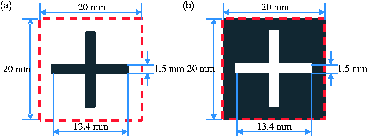
Schematic diagrams of patch-type and aperture-type cross-shaped conductive units. (a) Patch-type cross-shaped unit; (b) aperture-type cross-shaped unit.
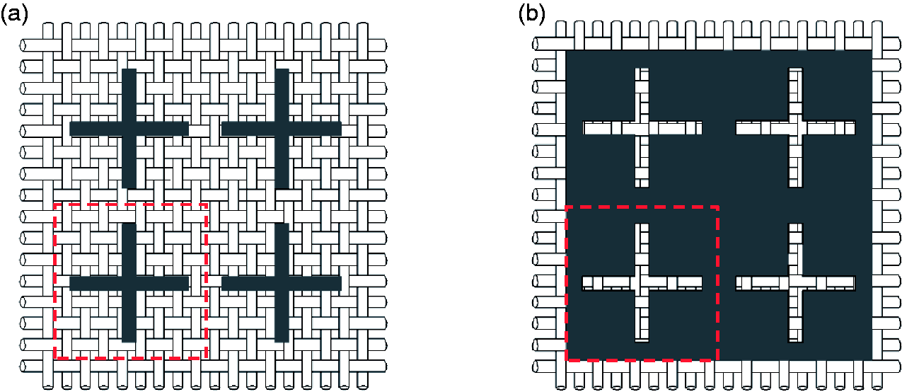
Schematic diagrams of single-layer patch-type and aperture-type cross-shaped frequency selective fabrics (FSFs). (a) Patch-type cross-shaped FSF; (b) aperture-type cross-shaped FSF.
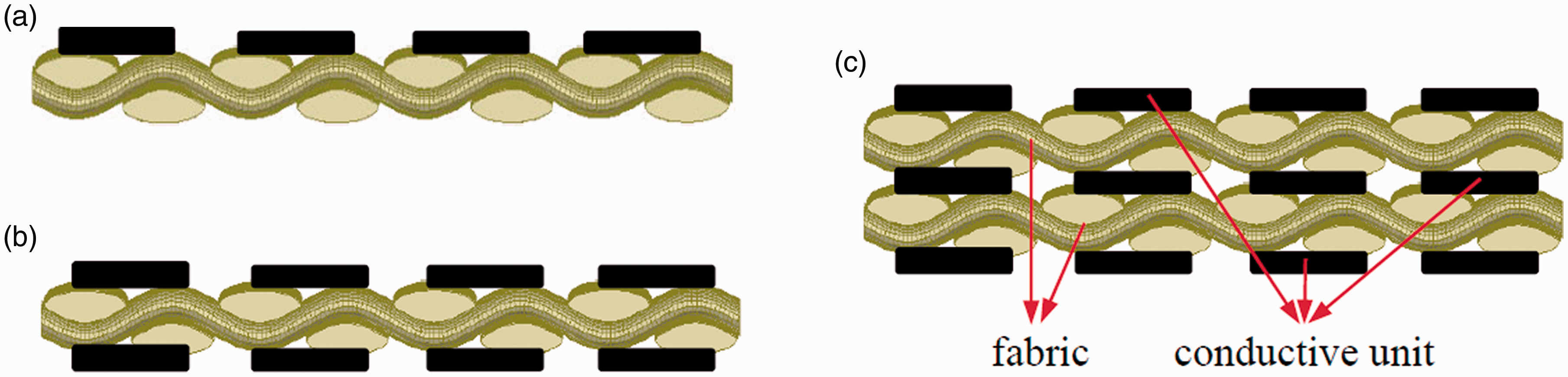
Side views of single-layer, double-layer and three-layer patch-type frequency selective fabrics (FSFs). (a) Side view of single-layer patch-type FSF; b) Side view of double-layer patch-type FSF and (c) Side view of three-layer patch-type FSF.
In this paper, nine samples were designed and prepared, including single-layer, double-layer and three-layer structures. Table 1 is the design table of experimental samples.
The design table of experimental samples
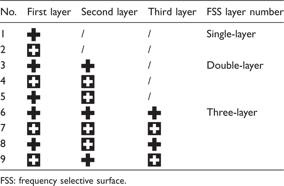
FSS: frequency selective surface.
Sample preparation and testing process
The samples in this paper were prepared by the computer engraving method. First, the fabric was closely attached with aluminum foil with an adhesive sticker to form composite materials. Then the graver was driven by the engraving software for periodic cutting and the excess metal foil was stripped to make the single-layer FSF. Finally, according to the design requirements, the single-layer structure was compounded to form stable double-layer and three-layer FSFs.
The Graphtec CE6000-60 engraving machine was used for sample preparation. The cotton warp backed weave fabric with the thickness of 0.8 mm was adopted for the dielectric layer, and the density of arrangement was 110 × 280 in 10 cm. The dielectric coefficient value was tested to be approximately equal to the vacuum using the parallel plate method, as the frequency of the incident wave was above 1 GHz. The aluminum foil with the thickness of 0.08 mm and square resistance 3.62 × 10⁻⁴ Ω/sq was selected to form the conductive FSS layer. By repeatedly adjusting the machine operating parameters, such as tool pressure, speed, and so on, the sample can be prepared with a relatively smooth conductive pattern without obvious damage.
By adjusting the position and angle of the horn antenna and the absorbing wall, the electromagnetic transmission characteristics of the samples under different incidence angles and polarization modes can be tested using the free-space method. Figure 4(a) and (b) show the preparation and testing process of cross-shaped FSF samples.
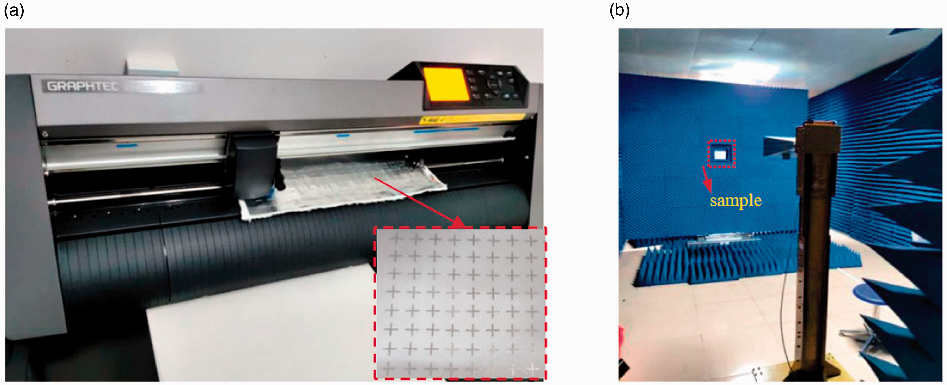
Preparation and testing process of cross-shaped frequency selective fabric (FSF) samples. (a) Sample preparation process; (b) sample testing process.
Analysis and discussion
Single-layer cross-shaped FSFs
Influence of polarization mode
Before analyzing the influence of FSS layers on electromagnetic transmission characteristics, the single-layer FSFs should be first studied. As the electromagnetic wave is perpendicularly incident, the transmission coefficients of no. 1 and no. 2 samples under two electromagnetic wave polarization modes were tested and shown in Figure 5. In order to explore the electromagnetic transmission characteristics of two complementary samples more deeply, the characteristic parameters of four transmission coefficient curves are extracted and listed in Table 2.
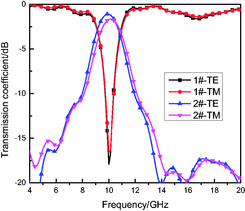
Transmission coefficients of single-layer frequency selective fabrics (FSFs) under different polarization modes.
Transmission characteristic parameters of no. 1 and no. 2 samples
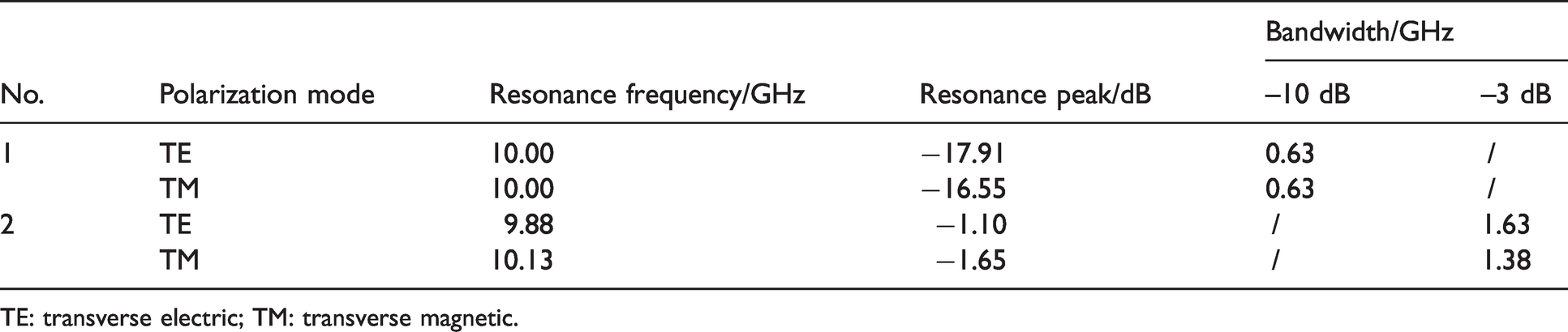
TE: transverse electric; TM: transverse magnetic.
Figure 5 shows that no. 1 and no. 2 samples have apparent frequency selective characteristics in the test frequency range, respectively, showing band-stop and band-pass characteristics. The transmission coefficient curves under two polarization modes were basically consistent, indicating that the polarization mode had little effect on the electromagnetic transmission characteristics of cross-shaped FSFs. For the patch-type sample, the resonance frequencies under two polarization modes were both 10 GHz and the –10 dB bandwidth values were both 0.63 GHz, and the resonance peaks were severally –17.91 dB and –16.55 dB. For the aperture-type sample, the resonance frequencies under two polarization modes were severally 9.88 GHz and 10.13 GHz, and the resonant peaks were, respectively, –1.10 dB and –1.65 dB, and the –3 dB bandwidth values were 1.63 GHz and 1.38 GHz severally, with a little difference.
The cross-shaped FSFs had basically the same characteristics under two polarization modes, which could be attributed to the fact that the cross-shaped conductive units were centrosymmetric, and also there was no significant error in the size and arrangement of the conductive units. In the follow-up study of this paper, the electromagnetic transmission characteristics under TE polarization mode were deeply analyzed and compared. The testing results under transverse magnetic (TM) polarization are no longer discussed.
Influence of incidence angle
In order to explore the influence rule of the incidence angle of electromagnetic wave, the electromagnetic transmission characteristics of no. 1 and no. 2 samples were tested and are shown in Figure 6(a) and (b). In the test process, the incidence angles were selected as 0°, 15°, 30°, 45° and 60°. It is noteworthy as the electromagnetic wave is incident perpendicularly to the FSFs, the incidence angle was 0° instead of 90°. In order to explore quantitatively the influence the of incidence angle, the transmission characteristic parameters of each transmission coefficient curve were extracted and are shown in Figure 7.
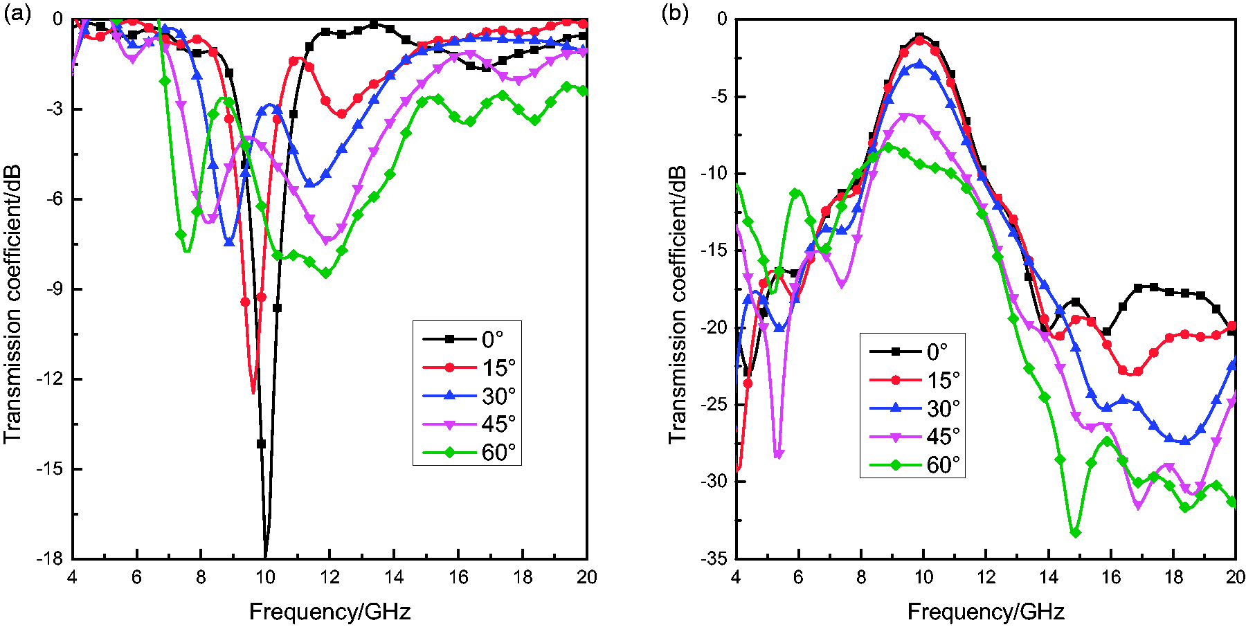
Transmission coefficients of single-layer frequency selective fabrics (FSFs) at different incidence angles. (a) No. 1 sample test results; (b) no. 2 sample test results.
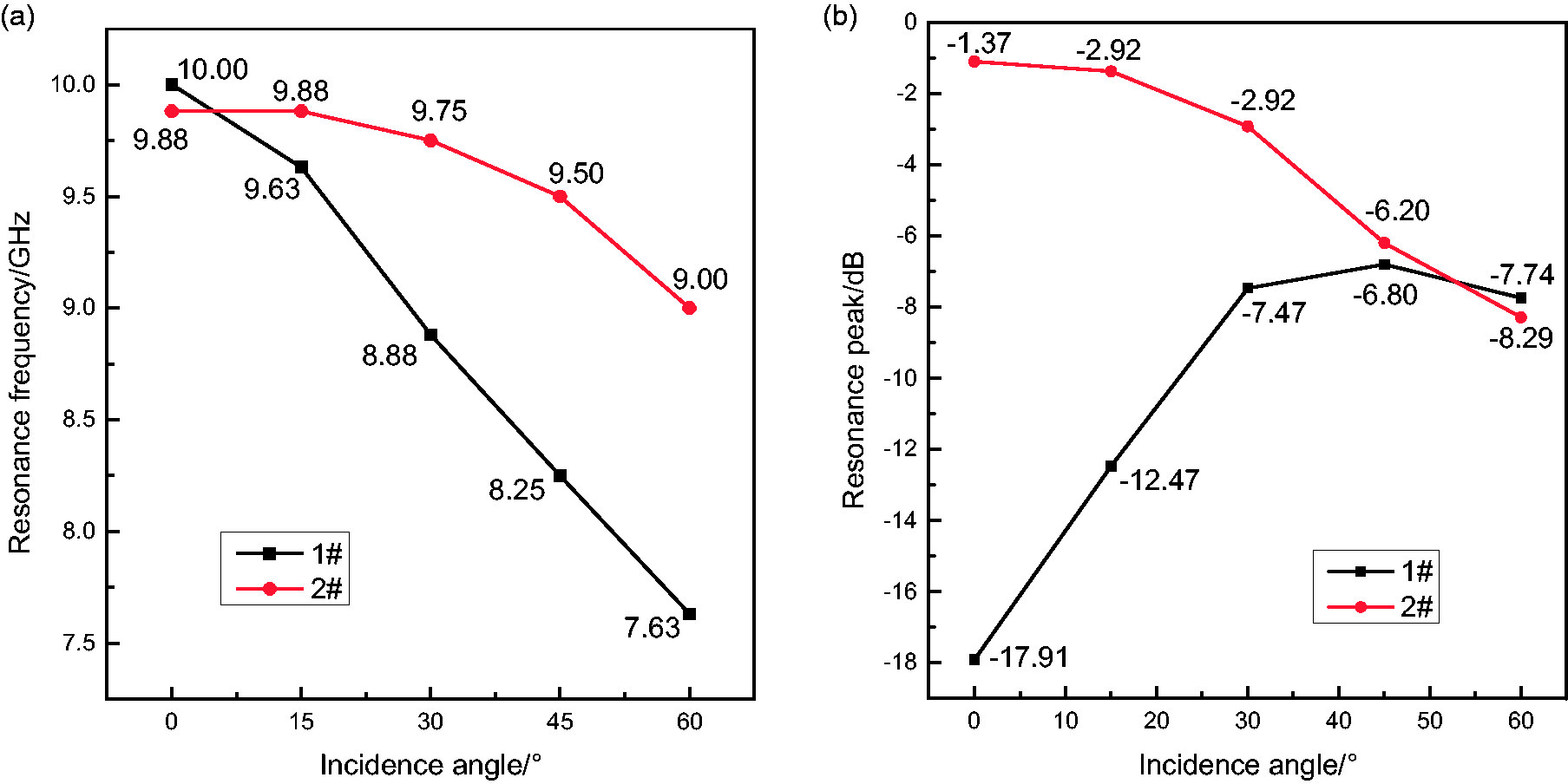
Influence of incidence angle on transmission characteristic parameters. (a) Influence on resonance frequency; (b) influence on resonance peak.
Figure 6 shows that the electromagnetic wave incidence angle has a major impact on the transmission coefficient. For the patch-type sample, with the increase in the incidence angle, the transmission coefficient curve moved upward and the resonance characteristics were gradually weakened. For the aperture-type sample, with the increase in the incidence angle, the transmission coefficient curve moved downward and always maintained a distinct resonance phenomenon. Figure 7 shows that the influence of the incidence angle on the resonance frequency and resonant peak was regular. With the increase in the incidence angle, the resonance frequencies of the two samples were gradually decreased, but the reduction degree was different. The resonance peak of the patch-type sample gradually increased, while that of the aperture-type sample decreased.
In addition to the resonance frequency and resonance peak, the incidence angle of the electromagnetic wave also exerted an influence on the bandwidth value. For the patch-type sample, when the electromagnetic wave was vertically incident, the –10 dB bandwidth was 0.63 GHz. As the incidence angle of the electromagnetic wave increased to 15°, the bandwidth reduced to 0.25 GHz. With the further increase of the incidence angle, the transmission coefficient was greater than –10 dB in the whole test band and the band-stop characteristic became poor. For the aperture-type sample, when the electromagnetic wave was vertically incident, the –3 dB bandwidth was 1.63 GHz. As the incidence angle increased to 15° and 30°, the bandwidth decreased to 1.38 GHz and 0.38 GHz severally. With the further increase in the incidence angle, the transmission coefficient was less than –3 dB and the band-pass characteristics were weakened.
The above data show that the designed cross-shaped FSFs had a certain angle stability, but when the incidence angle got comparatively large, the frequency selective characteristics became poor. In the follow-up study of this paper, the electromagnetic transmission characteristics tested in the case of perpendicular incidence were deeply analyzed and compared. The testing results at other incidence angles are no longer discussed.
Double-layer and three-layer cross-shaped FSFs
Transmission characteristics of FSFs with the same FSS layers
Based on the study of single-layer FSFs, double-layer and three-layer FSF samples with the same FSS layers were designed, prepared and tested. The transmission coefficients of patch-type and aperture-type samples were respectively shown in Figure 8(a) and (b). In order to explore further the influence of the FSS layer number on electromagnetic transmission characteristics, the characteristic parameters of each transmission coefficient were extracted and are listed in Table 3.
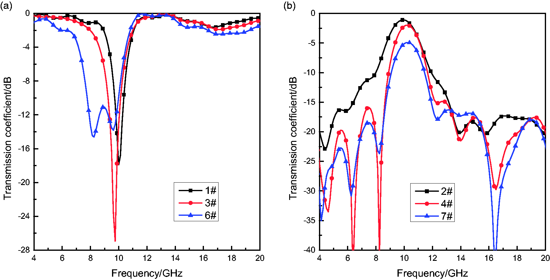
Transmission coefficients of frequency selective fabrics (FSFs) with the same frequency selective surface (FSS) layers. (a) Patch type (no. 1, no. 3 and no. 6 samples); (b) aperture type (no. 2, no. 4 and no. 7 sample).
Transmission characteristic parameters of FSFs with the same FSS layers
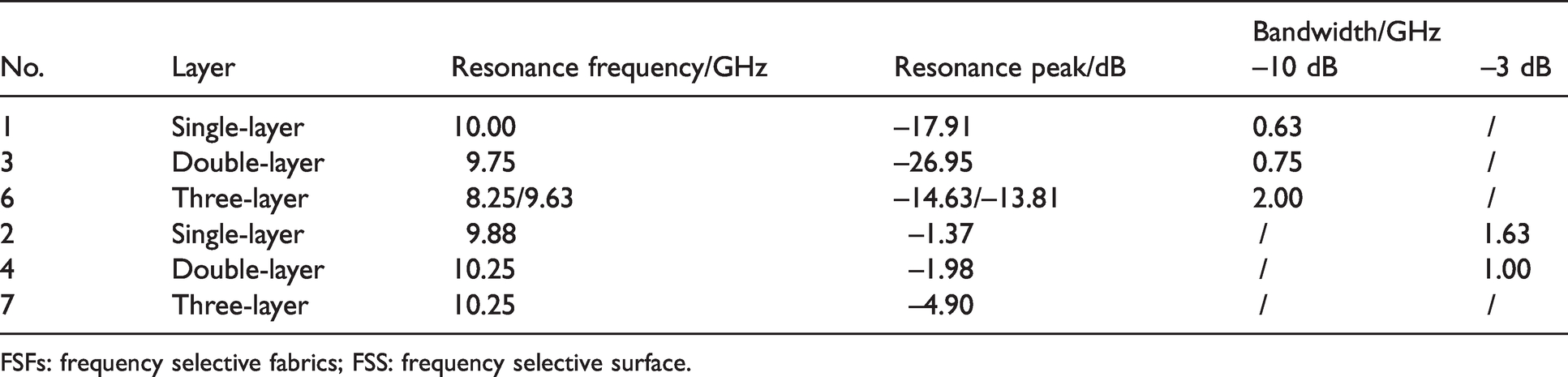
FSFs: frequency selective fabrics; FSS: frequency selective surface.
Figure 8 shows that the FSS layer number has a certain effect on the transmission coefficient. Compared with the single-layer sample, the resonance peak of the patch-type double-layer sample significantly decreased, and the resonance frequency slightly decreased, while the bandwidth slightly increased. There were two evident resonance peaks in the transmission coefficient curve of the patch-type three-layer sample, and the corresponding resonant peaks were relatively large. The transmission coefficient curve of the aperture-type double-layer structure moved slightly downward, namely the resonance peak decreased and the bandwidth value was also significantly reduced. The transmission coefficient curve of the aperture-type three-layer structure continued to move downward, and the resonance peak was reduced to about –5.00 dB. Table 3 shows that the FSS layer number has a great influence on the resonance frequency and resonance peak. For example, compared with no. 1 sample, the resonance peak of no. 2 sample decreased by 9.05 dB, while the two resonance peaks of no. 3 sample increased by 3.28 dB and 4.10 dB, respectively, and the –10 dB bandwidth increased from 0.50 GHz to 2.00 GHz.
On the whole, compared with the single-layer sample, the resonance peak of the patch-type double-layer sample and the bandwidth of the aperture-type double-layer sample were smaller, indicating that the double-layer samples had more ideal frequency selective characteristics. The transmission coefficient curves of the three-layer samples became irregular and the narrow-band transmission characteristics were weakened, especially the patch structure. The main reason for the above changes was that the single-layer and double-layer samples had only one fabric layer with the identical dielectric loss, and the spatial superposition of conductive units in the double-layer samples enhanced its frequency selective characteristics. Three-layer samples had two fabric layers and more dielectric loss, which interfered with the transmission of electromagnetic waves. The number increase of the same FSS layers did not necessarily effectively enhance the frequency selective characteristics, and the dielectric parameters of the fabric layer should be analyzed in detail.
Transmission characteristics of FSFs with the complementary FSS layers
Based on the study of FSFs with the same FSS layers, the FSFs with the complementary FSS layers were designed, prepared and tested. Figure 9(a) and (b), respectively, show the transmission coefficients of patch-type and aperture-type samples.
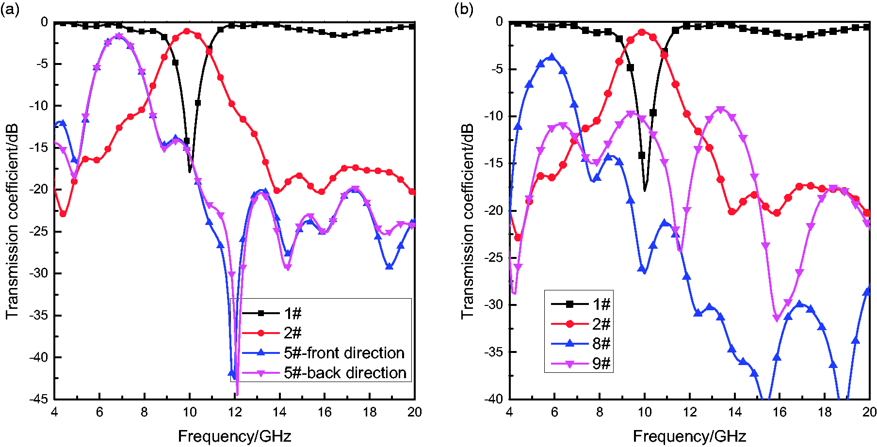
Transmission coefficients of frequency selective fabrics (FSFs) with the complementary frequency selective surface (FSS) layers. (a) Patch type (no. 1, no. 2 and no. 5 samples); (b) aperture type (no. 1, no. 2, no. 8 and no. 9 samples).
Figure 9(a) shows that the transmission coefficient of the double-layer sample with the complementary FSS layers is markedly different from the single-layer sample. Resonance occurred at two frequency points, namely 6.75 GHz and 12.00 GHz, and the resonant peaks were –1.73 dB and –42.59 dB, respectively. In the high frequency band, transmission coefficient values were less than –20.00 dB and therefore the sample mainly presented band-pass characteristics. The –3 dB bandwidth was 1.13 GHz and narrow-band transmission characteristics were enhanced. The test results in the front and back directions were basically the same, indicating that the electromagnetic losses in the two directions were identical.
Figure 9(b) shows that the transmission coefficient curves of the three-layer samples have remarkable fluctuations compared with the patch-type as well as aperture single-layer FSF samples. For the ‘patch + aperture + patch’ sample, resonance occurred at 5.75 GHz and the resonance peak was –3.78 dB, and the sample exhibited band-pass characteristics. For the ‘aperture + patch + aperture’ sample, resonance occurred at multiple frequency points, but the resonance peaks were all less than –10.00 dB, with poor band-pass characteristics. Although the transmission coefficient values were not constant, the sample basically showed full shielding characteristics in the test band.
The above data show that the double-layer FSFs with the complementary FSS layer mainly had band-pass characteristics, and the bandwidth value became smaller. The electromagnetic loss of the three-layer FSFs was large, resulting in the decrease of the resonant peak, which was consistent with the change rule of FSFs with the same FSS layers. In the subsequent research work, the comprehensive influence of the FSS layer and fabric layer should be considered.
By comparing the results of samples nos 1∼9, we know that the FSFs with the same FSS layers showed coincident frequency selective characteristics, but the resonance frequency, bandwidth as well as the peak value may change in varying degrees. The FSFs with the complementary FSS layers mainly showed band-pass characteristics, but the characteristics were more complicated and need further study.
Mechanism analysis using equivalent circuit model
To explore the electromagnetic transmission mechanism of double-layer and three-layer FSFs, the equivalent circuit model was built for analysis. Compared with the single-layer structure, the equivalent circuits of double-layer and three-layer structures became more complicated. Figure 10(a) and (b) show two kinds of three-layer FSFs schematic diagrams, and Figure 10(c) and (d) show the corresponding equivalent circuit diagrams.
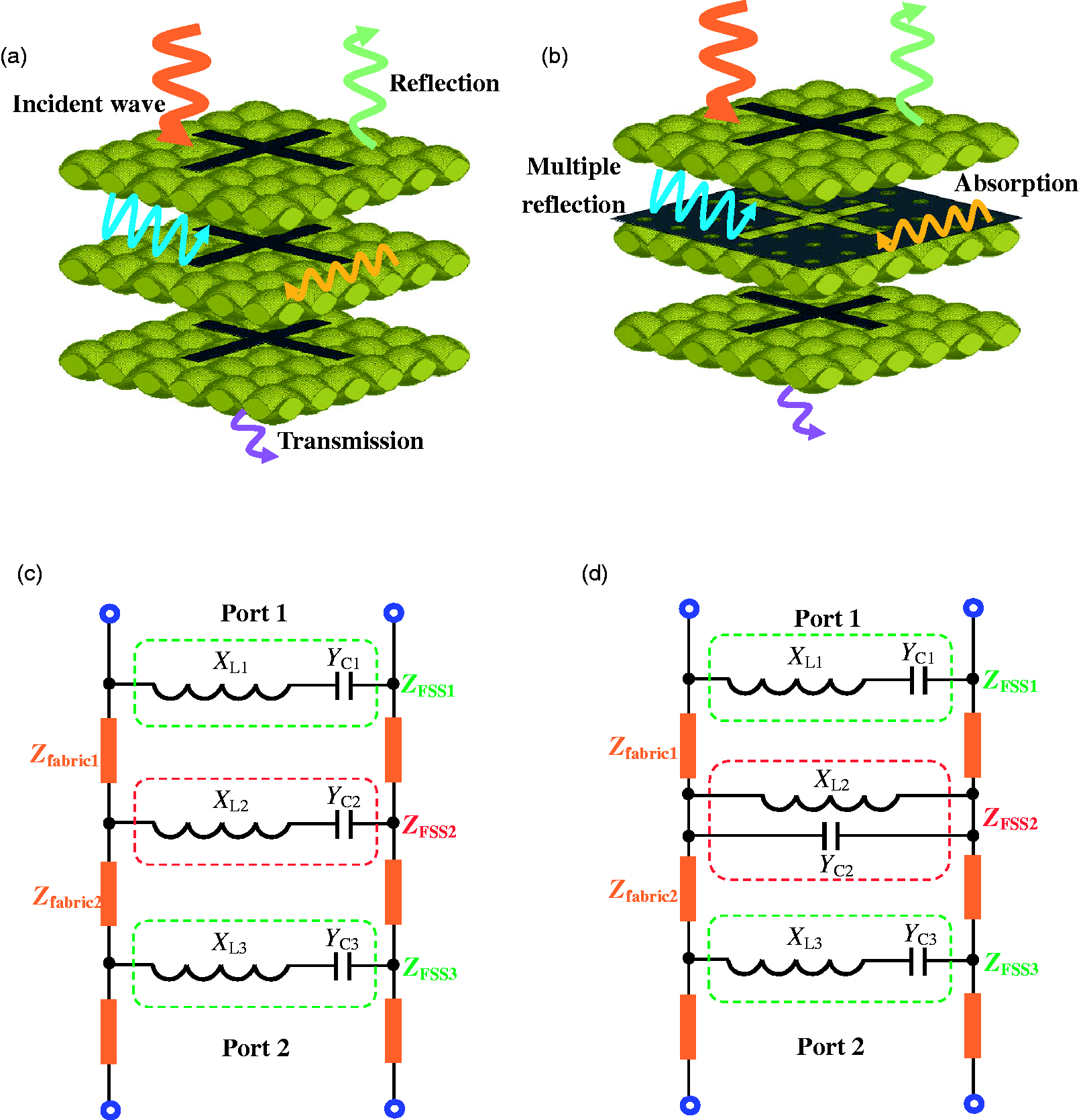
Two kinds of three-layer frequency selective fabric (FSF) schematics and equivalent circuit diagrams. (a) ‘Patch + patch + patch’ FSF; (b) ‘patch + aperture + patch’ FSF; (c) ‘patch + patch + patch’ equivalent circuit; (d) ‘patch + aperture + patch’ equivalent circuit.
Figure 10(a) and (b) show that as the electromagnetic wave interacts with the FSF, the incident wave will be mainly reflected, absorbed and transmitted. The FSF structure determined the energy conversion form of the electromagnetic wave. According to the basic principle of the equivalent circuit, the patch-type cross-shaped unit was equivalent to the series connection of capacitance and inductance, and the aperture-type cross-shaped unit was equivalent to the parallel connection of capacitance and inductance. 1 The equivalent circuit of the three-layer structure was the parallel connection of the equivalent circuit of each layer, as shown in Figure 10(c) and (d). In Figure 10, XL and YC are the inductance and capacitance of the FSS layer, ZFSS is the characteristic impedance. The fabric layer can be equivalent to a short transmission line with the length h, and its impedance value Zfabric is related to the dielectric constant of the fabric.
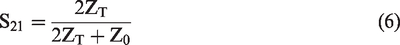
The total characteristic impedance ZT of three-layer FSFs can be calculated by equation (1), and the characteristic impedance of the fabric layer can be calculated by equation (2). For the patch-type and aperture-type unit, the characteristic impedance of the FSS layer can be calculated by equations (3) and (4), respectively. The transmission coefficient S21 of the multilayer structure can be calculated by equation (6).1,23–25

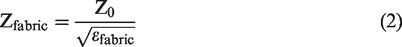


In equations (1) and (2), β is the transmission constant of the electromagnetic wave in fabric, h is the equivalent thickness of the fabric, Z0 is the impedance of free space and its value is 377 Ω, εfabric refers to the equivalent dielectric constant of fabric, which is related to yarn type, yarn structure, buckling wave height and fabric structure. In equations (3)∼(5), L and C are equivalent inductance and capacitance, respectively, which are related to the size and spacing of the cross-shaped unit, w and f refer to the angular frequency and frequency of electromagnetic waves, respectively.
The change in fabric type, structure, conductive unit type and size will affect the equivalent impedance of the multilayer structure, then exerting a great influence on the electromagnetic transmission characteristics, and this effect is usually nonlinear. In the subsequent study, the numerical method should be used to optimize the structure design and performance prediction. Based on the calculation formula of the single-layer structure and multi-layer circuit cascade mode, the electromagnetic transmission characteristics can be analyzed and computed step by step and the deep electromagnetic frequency response mechanism can be revealed.
Conclusions
The FSFs could be widely used in civil and military products, and the double or multilayer structure can greatly affect the electromagnetic transmission characteristics. In this paper, the cross-shaped FSFs with different FSS layers were selected for in-depth study. Nine samples with different unit types or layers were prepared and systematically tested, and the conclusions were obtained: (a) The polarization mode of the electromagnetic wave has little effect on the electromagnetic transmission characteristics of single-layer FSF samples, while the incidence angle has a relatively prominent effect. (b) For the FSFs with the same FSS layers, the increase in the number of FSS layers does not necessarily effectively enhance the transmission characteristics. (c) For the FSFs with the complementary FSS layers, the double-layer sample mainly exhibits band-pass characteristics and the three-layer sample has a large electromagnetic loss, resulting in the decrease of the resonant peak. (d) The fabric type, structure, conductive unit type and size will affect the equivalent impedance of FSFs, thus further influencing the electromagnetic transmission characteristics. The research work has referential significance for designing FSFs with various electromagnetic transmission characteristics and developing diverse soft filtering products. In future research, the FSFs with other conductive units and more layers should be studied systematically.
Footnotes
Declaration of conflicting interests
The author(s) declared no potential conflicts of interest with respect to the research, authorship, and/or publication of this article.
Funding
The author(s) received no financial support for the research, authorship, and/or publication of this article: This work was supported by the Natural Science Foundation of Fujian Province, China (2019J01740, 2021J05187); the Education and Scientific Research Foundation for Middle-aged and Young Scientist of Fujian Province, China (JT180377, JAT190527); the Quanzhou City Science & Technology Program of China (2018K002, 2020C039R); the Startup Foundation for Docotors of Quanzhou Normal University (H18024, H18028); and the Innovation and Entrepreneurship Training Project for College Students (202010399113).