
Abstract
As an auspicious composite material, three-dimensional orthogonal woven E-glass/epoxy composites (3DOWC) are associated with drilling processes to assemble the parts for obtaining the desired shape and for the improvement of the component’s quality. This study investigated the axial tensile properties of 3DOWC with 6 mm drilled holes (DH). For comparison, two-dimensional woven E-glass/epoxy laminated composites (2DWC) with the same drilled hole size were also tested. To analyze the effects of holes on the microstructure properties, the finite element (FE) software ABAQUS/Standard was employed to simulate the tensile properties of composites. Hashin damage criteria were used to predict the failure modes of the composite. The stress and strain curves were obtained to compare the numerical and experimental results at the same load condition. The comparisons illustrated the existence of a good agreement between the experimental and finite element method (FEM) results. In addition, scanning electron microscope (SEM) images were used to analyze failure modes and fracture mechanisms. Various degradation phenomena were observed especially fiber fracture, matrix cracking, and tow debonding also less delamination was noticed in 3DOWC than 2DWC.
For decades, drilling played an essential machining operation role for making riveted or bolted assemblies in carbon fiber-reinforced polymers CFRP components in industries. 1 Numerous pieces of literature focused on machining parameters and drill calculation for composites based on mechanical drilling.2–6 Also, some researchers noticed that structural changes affect the open-hole performance of composites, such as unidirectional, laminated, three-dimensional (3D) woven fabrics, etc. Drilled layered components, reinforced by unidirectional fibers, fiber mats, or two-dimensional (2D) woven fabrics lose significant energy due to stress concentration, corrosion, and microcracks.7–9 For instance, Haery et al. 7 investigated 2D woven fabric glass/epoxy composite laminates with the tensile strength decreased and hole diameter increased from 5 mm to 10 mm; the maximum decreased ratio was up to 29.23%. plates with open-hole decreased 20% to 40%, and the degradation ration became lower along with the thickness increased.
Khashaba et al. 8 proposed that the net and gross notched bending strengths of the notched glass fiber reinforced epoxy (GFRE) composites decreased in a linear relationship, with increasing hole diameter and the maximum decreased ratio was up to 50%, which indicated the significant property of degradation. Palanikumar et al. 10 developed an empirical model to investigate the effect of delamination in drilling of GFRP composites.
Meanwhile, other reports proposed that the 3D woven composites possessed more stable open-hole mechanical behaviors.11–14 Nakai et al. 11 investigated braided composites with two different types of circular hole obtained by the braided hole process and the mechanical drilling process. Nakai et al. investigated the influence of the two different types of circular holes (braided hole and machined hole) on the mechanical properties of the braided composites. Shaw et al. 14 found that the tensile strength of a 3D angle-interlock woven C/SiC composite with small holes (1–2 mm in diameter) exhibited a frail affectability to the presence of holes, no matter what the manner in which the holes were introduced. Xu et al. 15 discussed the fracture mechanisms of 3D orthogonal woven E-glass/epoxy composites (3DOWC) with drilled and molded-in holes, and investigated the open hole impacts on the performance of composites. Hence, when compared with traditional laminated materials, 3D textile structural composites are more promising and attractive candidates for complicated load-bearing structures.
Despite interest in the experimental approaches, Though, people done a lot of experimental research work on this area, there are few works in the literature focusing on finite element (FE) analysis, the effects of structure on the open-hole performance of composites. The FE analysis is a powerful tool that can be used to support testing, avoid technical problems, and elevate cost. Singh et al. 16 present a FE approach to study the drilling characteristics of unidirectional-GFRP (UD-GFRP) composite laminates. Chakladar et al.17 used a macro-mechanical approach to study the drilling responses on woven GFRP. Rakesh et al. 18 used the FEM approach to investigate delamination on fiber reinforced plastics with different drilling parameters. Singh et al. 18 carried out an experiment on unidirectional GFRP to find out the factors effecting delamination by finite element method (FEM). Haoqi Zhang et al. investigated mechanical performance and failure modes of 3D printed woven composite plates with 6 mm tailored woven hole and drilled hole. FEM and Hashin failure criteria were used to investigate the failure modes. Furthermore, the tensile and shear loading performance was studied. 19
From all the research above, we can find that the studies of the drilling research of composite mainly focus on 2D laminated structure, and are less involved in the 3DOWC. Recently, 3DOWC gradually replacing the 2D laminated structure has attracted more and more attention due to the advantages of lower cost and good structural integrity. Furthermore, 3DOWC structures are composed of straight fibers in three orthogonal directions, and the Z-yarns run through the thickness direction and bind warp yarns and weft yarns together. This structure has remarkably higher in-plane strength and better integrated property than the laminated composites and even “conventional” 3D interlock woven composite structures.20,21 Anyhow, the mechanical properties and fracture mechanisms of 3DOWC with drilled holes are seldom investigated.
This study prepared the 3DOWC with drilled holes. The effects of the open hole on the performance of composites were studied by experimental and finite element methods of microstructure. Moreover, the fracture mechanisms of all composites were analyzed and the mechanical properties of 2D woven laminated composites (2DWC) were investigated for a comparison study with those of the 3DOWC.
Materials and experiment
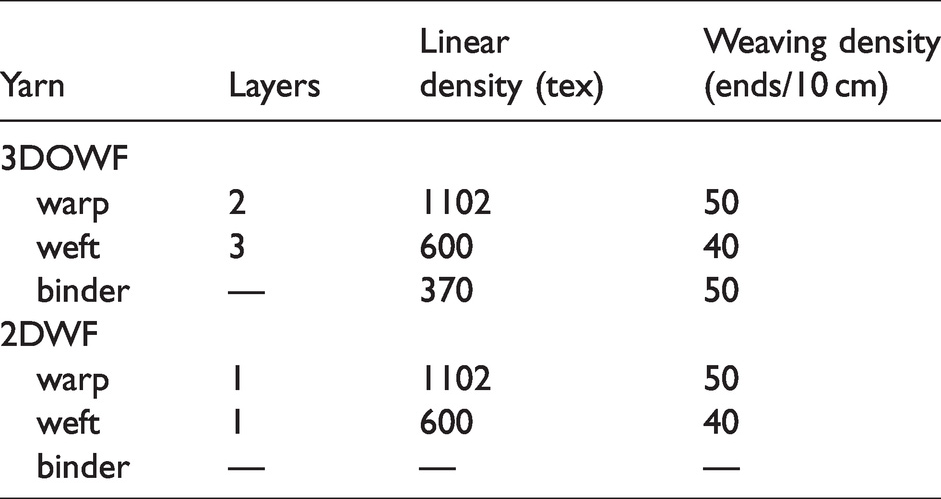
The 3D orthogonal woven fabric (3DOWF) and 2D plain woven fabric (2DWF) were made of E-glass fiber tows which were supplied by Jushi Group Co Ltd. The weave architectural parameters are listed in Table 1.
Weave architectural parameters of the three-dimensional orthogonal woven fabric (3DOWF) andtwo-dimensional plain woven fabric (2DWF)
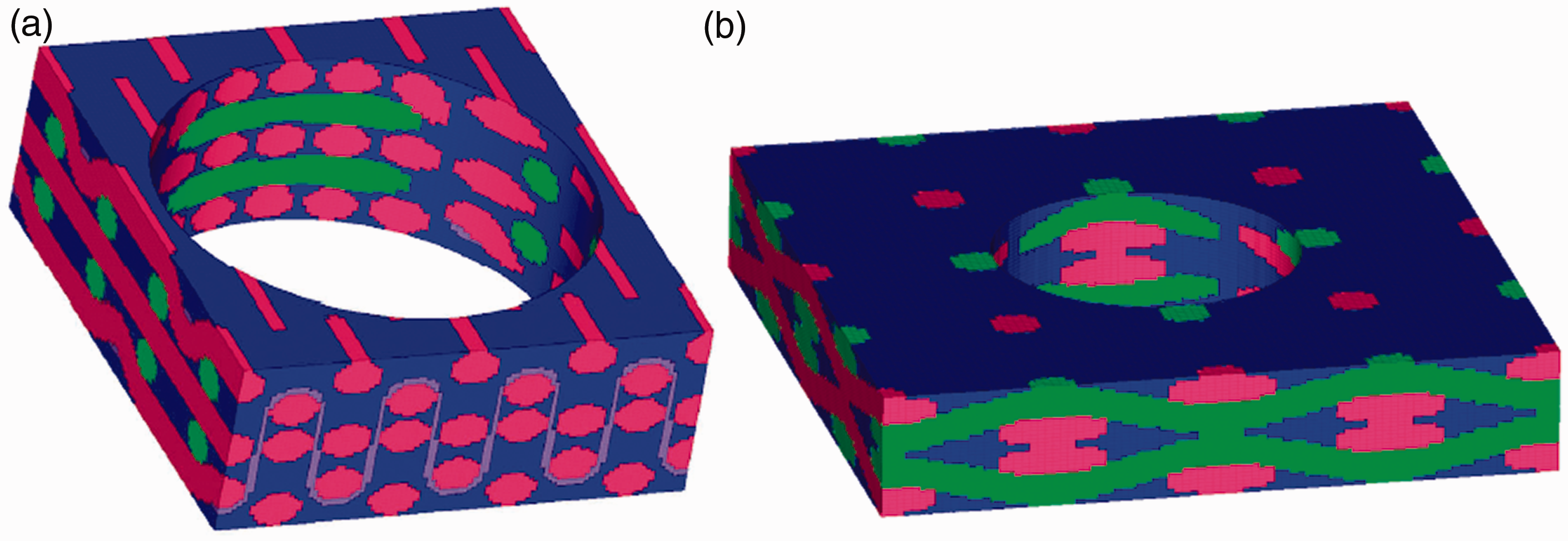
The vacuum-assisted resin transfer molding (VARTM) technique was adopted to manufacture the composites. Epoxy resin and curing agent were mixed in a mass ratio of 3:1 and the woven fabrics were infused with the above mixture. The employed JL-235 epoxy resin was manufactured by Jiafa Chemicals Co. Ltd. After infusion, the composites were kept in the mold under pressure at a cure temperature of 50°C for 1 h, followed with 7 h of post-cure at 70°C. The fiber volume fraction of the 3DOWC and 2DWC were both approximately 47%. The thicknesses of 3DOWC and 2DWC were around 2.5 mm and 2 mm, respectively. The structures of 3DOWC and 2DWC are shown in Figure 1.
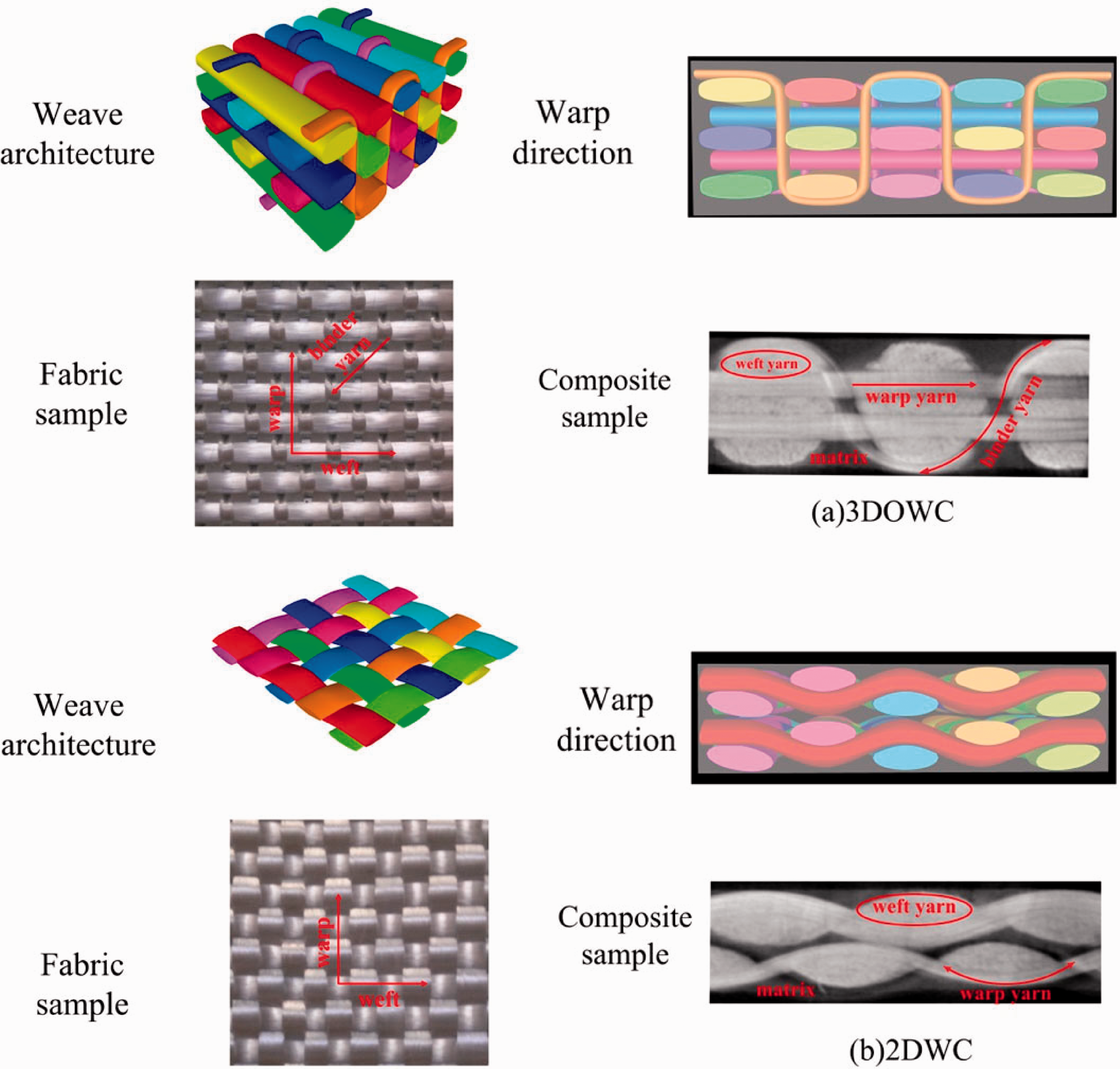
Weave structures of the (a) three-dimensional orthogonal woven E-glass/epoxy composites (3DOWC) and (b) 2D woven E-glass/epoxy laminated composites (2DWC)
The holes in the composites were introduced by drilling with a standard twist drill after a panel fabrication, namely a drilled hole (DH). The 6 mm diameter holes were prepared at the specimen center, as shown in Figure 2. The pictures are for two types of composites with holes: (a) 3D orthogonal woven composites with drilled hole (3DOWC-DH), (b) 2D woven composites with drilled hole (2DWC-DH). For the composites with drilled holes as shown in Figures 2(a) and 2(b), fibers around the hole were cut off, and the amount of load bearing fibers decreased.
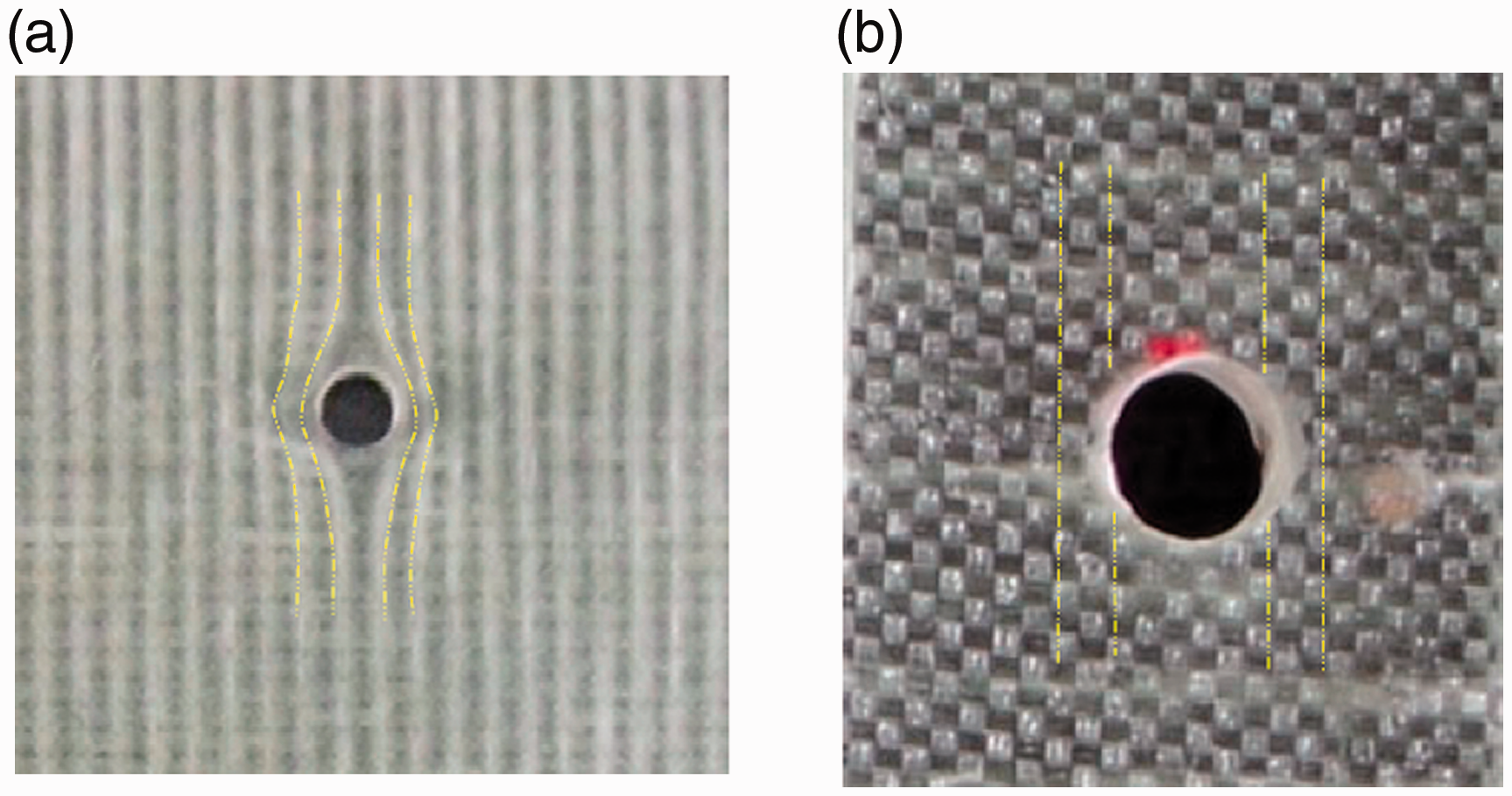
Pictures of composites with holes: (a) three-dimensional orthogonal woven composites with drilled hole (3DOWC-DH); (b) two-dimensional woven composites with drilled hole (2DWC-DH).
Tensile testing
Tensile testing was performed with a universal testing machine (WDW-20, HUALONG) using a 50 kN load-cell. The composite plate was cut into tested composite coupons along the warp direction. According to GB/T 1447–2005, the sample size was 250 mm × 25 mm; the gauge length was 150 mm. Five samples were tested at the same room temperature and approximately 55% relative humidity under the tensile speed of 2 mm/min.
Scanning electron microscope (SEM, Hitachi TM3000) images were used to characterize tensile fracture surfaces. Using sample preparation for damage characterization. the 5 mm–10 mm (in height) test sample was placed on the sample platform vertically and the edges of a hole were observed.
Finite element analyses
In order to observe the internal structure of 2DWC and 3DOWC directly, such as stress concentration regions and failure areas, and to analyze the tensile damage propagation of materials and interface under tensile tests, a small-scale microstructure model was established by a CAE software CATIA (ver. V5-R21). It should be mentioned that the microstructure model can only qualitatively compare tensile deformation and damage areas with experimental results. For finite element analyses all the pre-processing operations were done by using HyperMesh (ver. 12.0), after that submitted for calculations in the commercially available finite element software package ABAQUS/Standard (ver. 6.10), and the post-processing was completed in ABAQUS and HyperView. The geometrical models of fabric and matrix are shown in Figure 3.
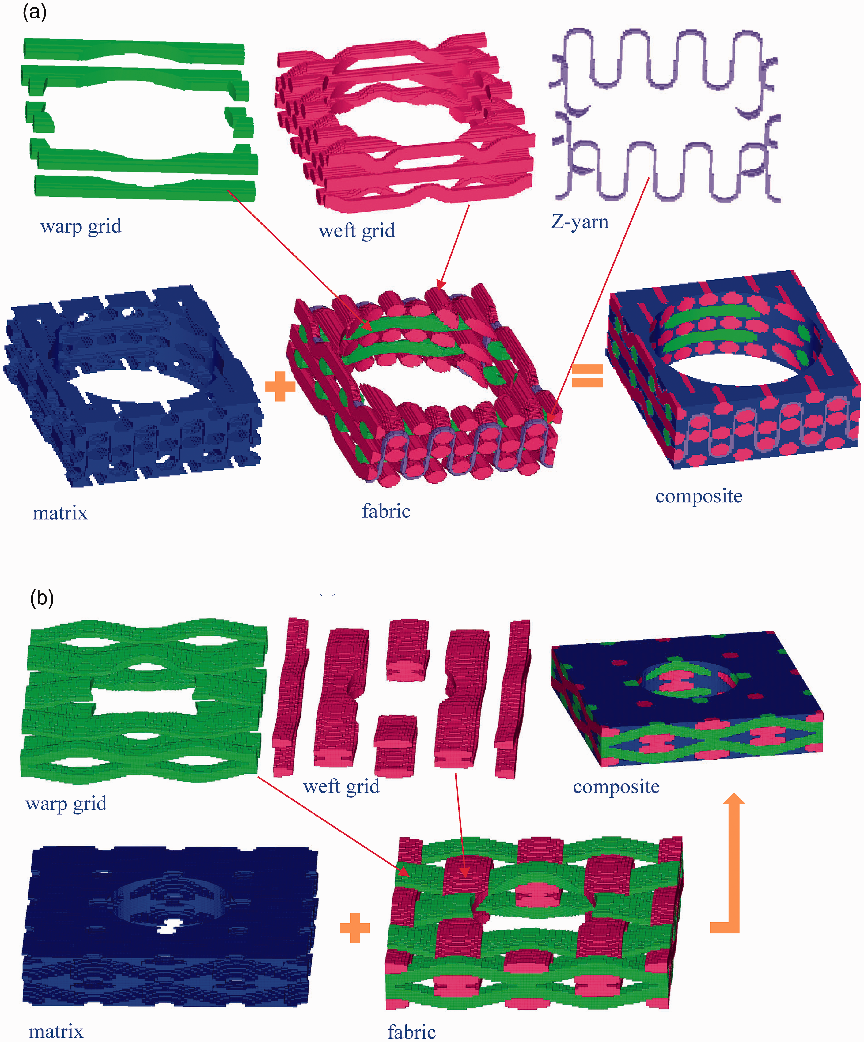
Idealized weave architectures: (a) three-dimensional orthogonal woven composites with drilled hole (3DOWC-DH), (b) two-dimensional woven composites with drilled hole (2DWC-DH).
The parameters of carbon fiber tows and resins to be used in finite element calculations are shown in Table 2.
The parameters of carbon fiber tows and resins
Considering the complexity of geometrical structure and the demand for a high-quality grid, the powerful finite element meshing software HyperMesh was used. The mesh scheme is shown in Figure 4. Matrix, warp, weft, and binding yarns were simulated by the body element, and the nodes were shared with each other. The 3DOWC-DH size of the body unit was 0.1 mm, with a total of 220,184 units. The 2DWC-DH size of the body unit was 0.1 mm, with a total of 196,080 units.
Mesh of the model: (a) three-dimensional orthogonal woven composites with drilled hole (3DOWC-DH); (b) two-dimensional woven composites with drilled hole (2DWC-DH).
The Hashin criteria have been implied to identify different failure modes of 3D textile composites. 22 The composite failure criteria were proposed by the Hashin criteria 23 to detect the failure modes in the fiber and matrix under tension failures modes. The failure modes included in Hashin’s criteria were as follows:
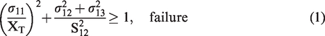
The tensile fiber failure for σ11 ≥ 0:

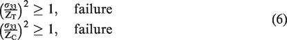
Tensile matrix failure for 
Compressive matrix failure for 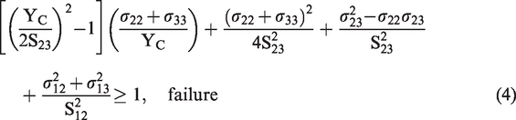

The two fabric structure models were loaded in the same way. RBE elements were established at two ends: one end was fixed (SPC1-6, marked with triangles), and the other with all degrees of freedom was fixed except the forced axial tension loading (SPC2-6). Rigid elements connect the ends, and the constraints and loads were applied to the primary nodes of the rigid elements. Figure 5 presents a sketch of the experimental under tension load upon 3DOWF and 2DWF samples.
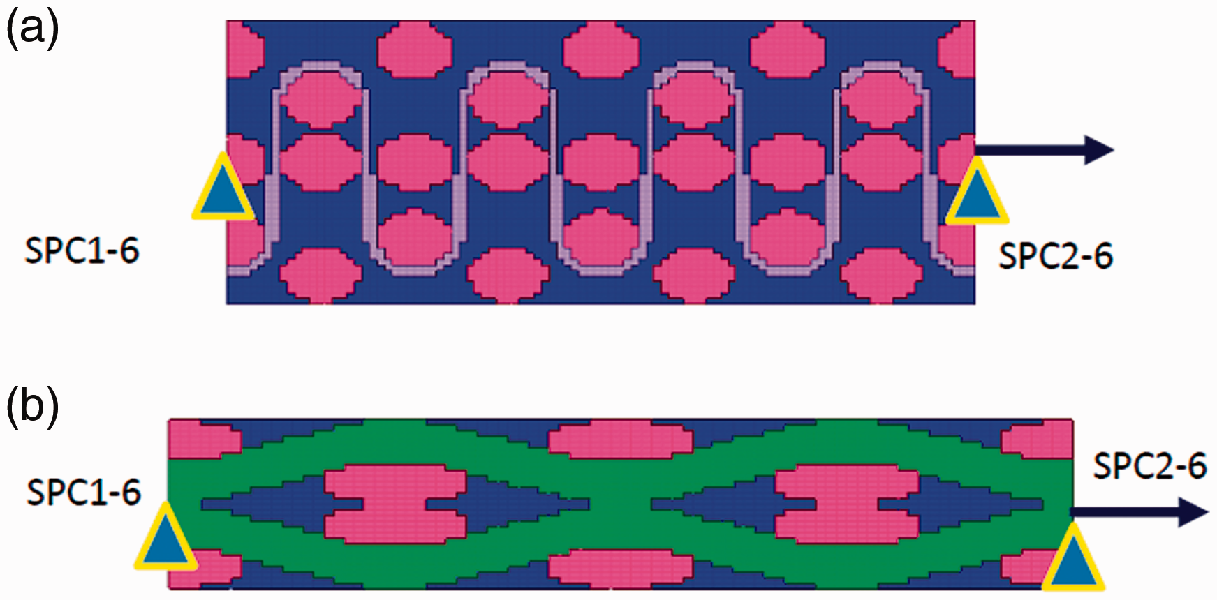
Meshed geometry of composite subjected to tension simulation: (a) three-dimensional orthogonal woven fabric with drilled hole (3DOWF-DH); (b) two-dimensional woven composites with drilled hole (2DWC-DH).
Results and discussions
Experimental results and FE model validation
The presented microstructure FE model was first validated by comparing the experimentally measured and numerically predicted global stress–strain curves for the 3DOWF and 2DWF under axial tension loading conditions. As shown in Figure 6, the FE model does well in predicting the axial tension mechanisms responses, capturing both the initial stiffness and damage-induced linearity behavior.
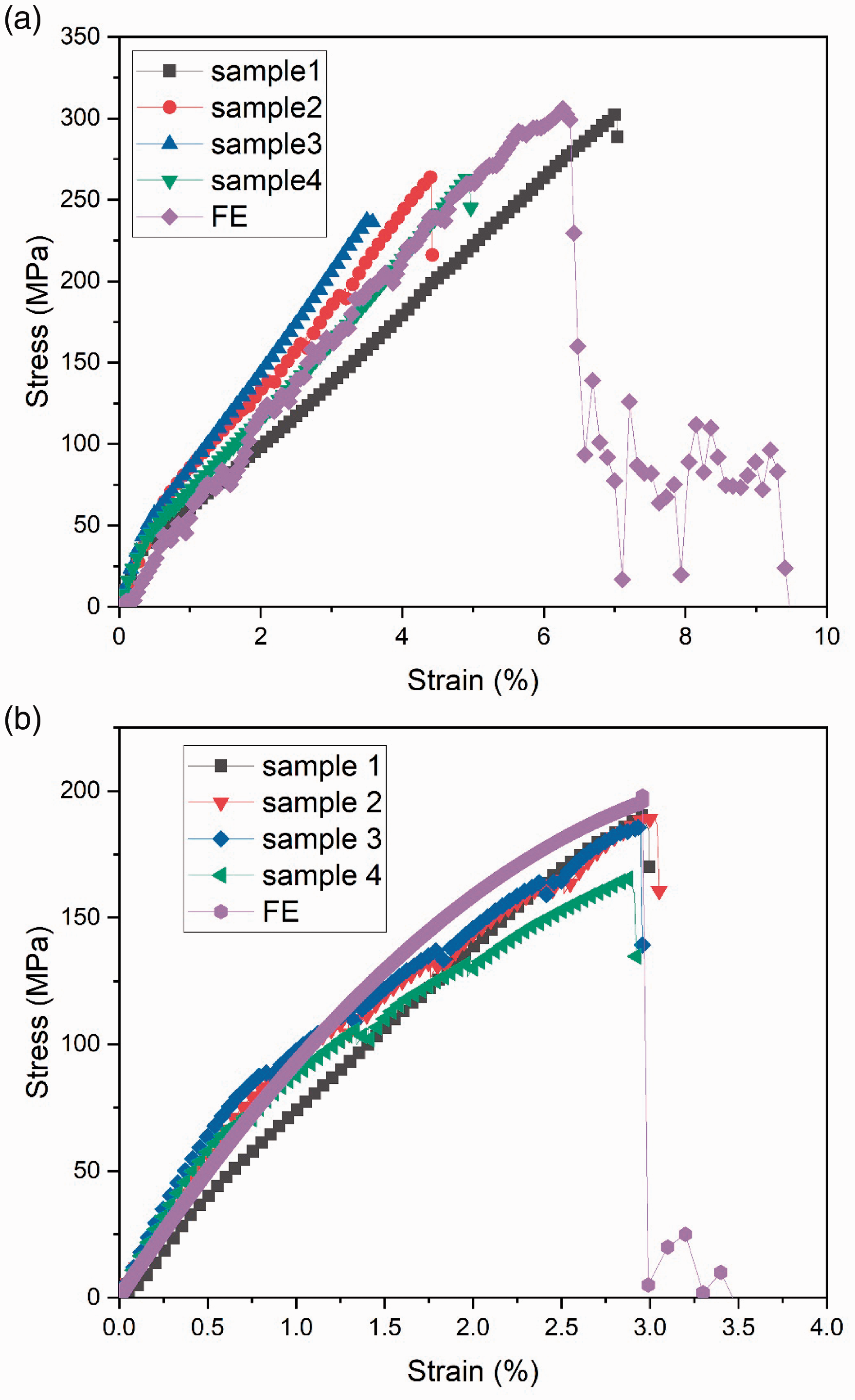
Tensile stress–strain curves: (a) three-dimensional orthogonal woven composites with drilled hole (3DOWC-DH); (b) two-dimensional woven composites with drilled hole (2DWC-DH).
For the sample in length along warp yarns direction, the stress–strain and FE result curve is shown in Figure 6. The specimens behaved nearly linearly up to final fracture, with ultimate stress of 307 MPa of 3DOWC-DH and 193 MPa of 2DWC-DH respectively.
According to the results, the 3DOWC-DH showed much higher tensile strengths than those of the 2DWC-DH, resulting in more aligned in-plane fiber orientation. Generally, the isotropic materials are more sensitive to structural defects or damages as far as the crack propagation is concerned. 3DOWC was quasi-isotropic in structure due to the evenly distributed and straight fiber orientated in three directions. At the same time, 2DWC was an inhomogeneous structure caused by the interlaced and crimped fibers and laminated structures. Compared with the 2DWC-DH, the 3DOWC-DH was found to have better integrated property and less broken fiber ends near the hole area, and the 2DWC will suffer delamination around the hole area, which may blunt the stress concentration and thus delay the degradation of the force-carrying capacity. 24 .
For FE simulation, the predicted stress–strain curves agree well with the tested results. The linear behavior of the stress–strain curves indicates that the specimens suffer damage continuously during the tensile tests, resulting in the inelastic behavior of pure matrix material, transverse cracking of the fiber bundles, and shear failure of the interfaces. A primary advantage in using a microstructure FE model was its capability for predicting the local deformation and damage behavior for materials with complex architecture.
Tensile failure analysis
As shown in Figures 7(a) and (b), SEM images of the tensile fracture surface depicted that 2DWC-DH underwent serious delamination as well as fiber breakage; while just fiber breakage was observed in 3DOWC-DH; this is because the through-thickness binder yarns (as shown in Figure 1) were able to prevent delamination cracks. Comparing with the 2DWC-DH, the 3DOWC-DH was found to have better integrated property and fewer broken fiber ends near the hole area. Through observation, we found that the extra reinforcement near the hole area prevented the stress concentration and crack growth around the hole, thus rendering higher tensile strength than other samples.
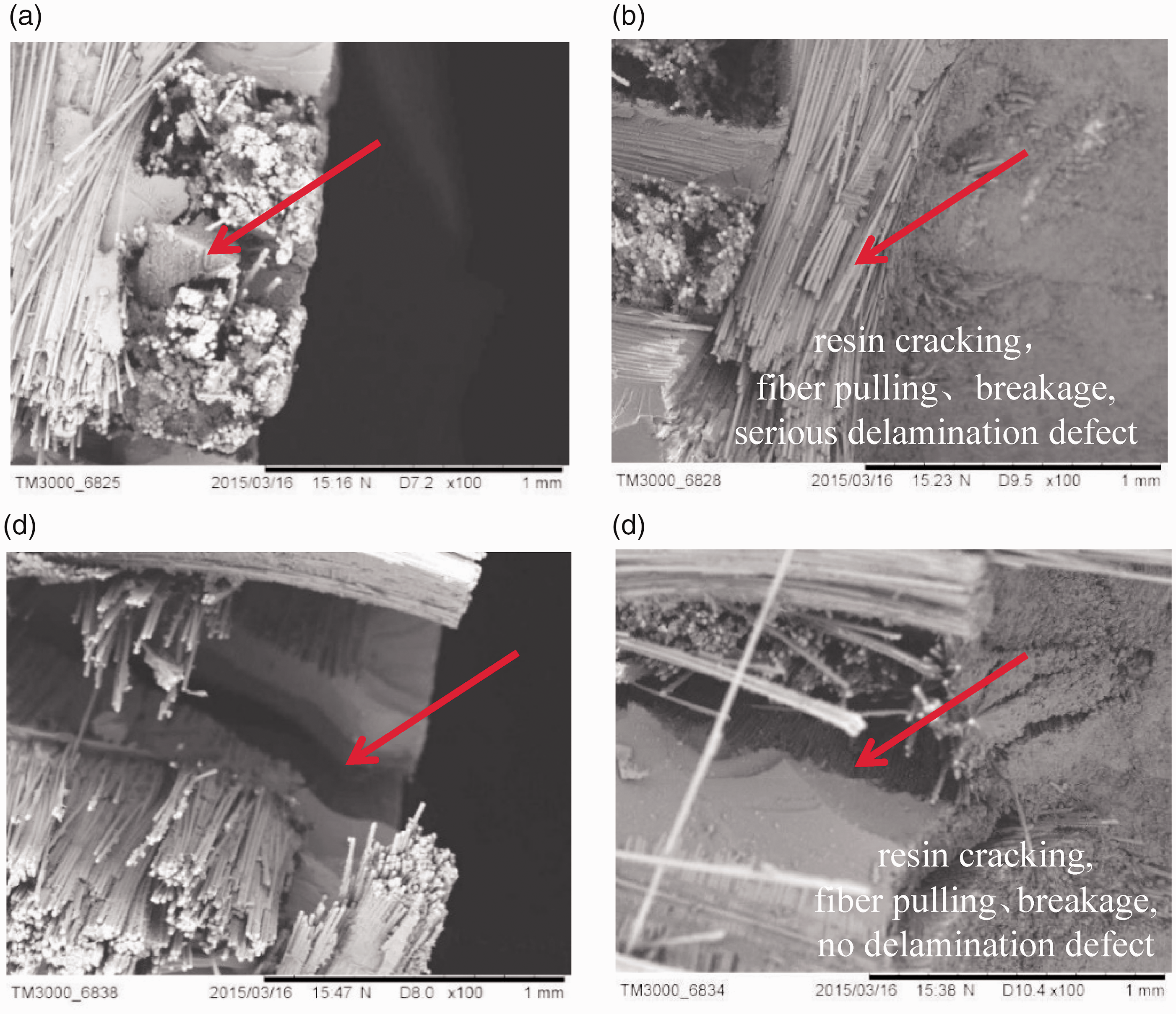
Scanning electron microscope (SEM) photos of tensile fracture surface around the hole area: (a) three-dimensional orthogonal woven E-glass/epoxy composites with drilled hole (3DOWC-DH); (b) two-dimensional woven composites with drilled hole (2DWC-DH).
Figure 8 shows the damage contours from the numerical simulation. The yarn and resin were destroyed at the thinnest part of the circular hole where part of the concentrated zone was. It can be seen from the figure that the stress was concentrated at the center, edge, and end of the hole. The serious delamination failure occurred in the 2DWC-DH, as shown in Figure 8(b), while the 3DOWC-DH structure has better integrity performance, and no delamination failure occurred in the fracture surface of the material.
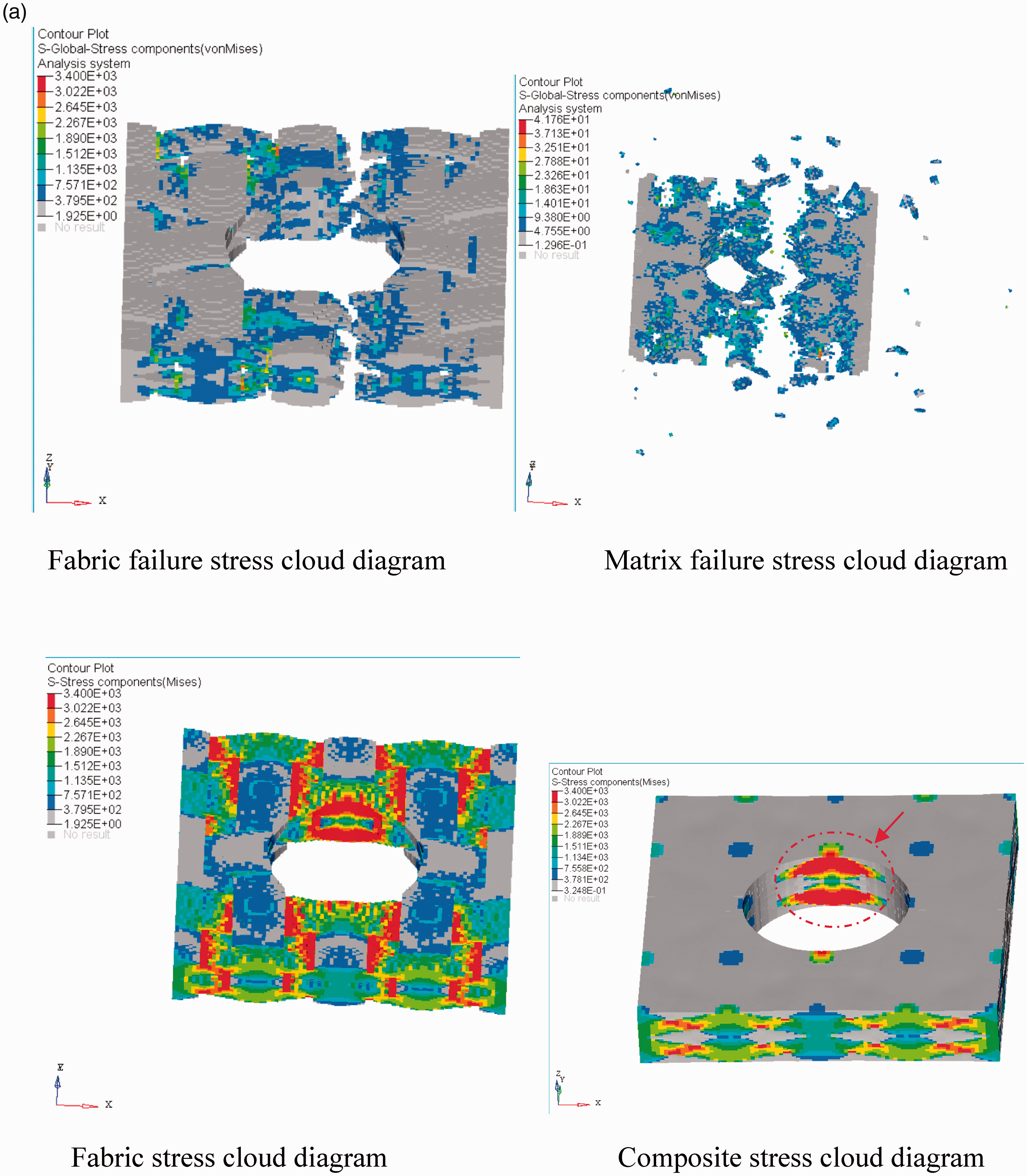
Simulated damage contours and images showing failure of composite: (a) three-dimensional orthogonal woven E-glass/epoxy composites with drilled hole (3DOWC-DH); (b) two-dimensional woven composites with drilled hole (2DWC-DH).
In the stretch process, the 3DOWC-DH suffered fiber breakage and matrix cracking under tensile loads. Due to the binding effect of 3D yarn, the non-crimped fiber and integrated structure allow all reinforcement fibers to take the load together and maximum stress is reached when the composite failure occurred. Due to the binding effect of z-yarns, the non-crimped fibers are bind the three-dimensional orthogonal woven fabric into a stable structure, which combines all reinforcement fibers to an integrity take the whole load together. In addition, 2DWC-DH possessed the worst fiber damage and matrix cracking under tensile load and presented most severe tensile damage as well as the lowest tensile strength. During tensile testing, the 2DWC-DH sample will create the delamination-damaged mode at first and then fibers broke at the maximum load occurred gradually.
Conclusion
The 3DOWC-DH and 2DWC-DH with drilled holes were fabricated, and experimental and numerical studies investigated their axial mechanical properties. According to the results, the 3DOWC-DH showed higher tensile strengths than the 2DWC-DH. The SEM photos showed that various damage modes such as fiber fracture, matrix cracking, and tow debonding exist in all composites.
The developed microstructure FE method showed a reasonably good correlation with the experimental results in terms of global stress–strain curves. The FE model showed the capability to predict the internal damage evolution process of fiber tows and interfaces. The main failure modes of the composite subjected to axial loads were fiber breakage at the edge of circular hole.
In the process of delamination, resin breakage occurs first, followed by fiber breakage or delamination. Delamination did not occur due to the binding effect of the 3D yarn. However, the delamination phenomenon was commonly observed in 2DWC but not 3DOWC because of the binding fiber in the z-direction. In addition, 2DWC-DH possessed the worst fiber damage and matrix cracking under tensile load and presented the most severe tensile damage as well as the lowest tensile strength.
Footnotes
Declaration of conflicting interests
The author(s) declared no potential conflicts of interest with respect to the research, authorship, and/or publication of this article.
Funding
The author(s) disclosed receipt of the following financial support for the research, authorship, and/or publication of this article: This work was supported by the Zhejiang Provincial Natural Science Foundation of China under Grant No. LGG21E050025, the Fundamental Research Funds of Zhejiang Sci-Tech University (Project Number: 20202113-Y), as well as the Fundamental Research Funds of Shaoxing Keqiao Research Institute of Zhejiang Sci-Tech University (Project number: KYY2021001G).