
Abstract
The compression properties of welded seams depending on welding parameters using the hot wedge and hot air welding technique, ultrasonic welding technique, and high-frequency welding technique were studied. The compression properties, expressed by parameters such as compressional energy WC, compressional resilience RC, linearity LC, and compressibility C, are important information about the welded seam quality in terms of touch, voluminosity, stiffness, and flexibility of the welded seam. KES-FB and FAST measurement systems were used to test the compression properties of the welded seams. Based on the analysis of the results obtained, the influence of the welding parameters on the compression properties of the welded seam was determined. The results of the investigation showed that improperly selected welding parameters, such as the supply or introduction of too much heat into the material to be welded or too long exposure of the material in the weld zone to heat, result in welded seams with expressive extrusion edges, which affects the quality of the welded seams. These welded seams have very low values of compressional resilience RC and very high values of compressional energy WC and compressibility C.
Keywords
In this work, the welding parameters of four welding techniques and their influence on the compression properties of welded seams were examined. To achieve quality joints it is necessary to meet several criteria. Many authors write about characteristics that joints must have to be considered good quality. 1 –3 Therefore, it is necessary to optimize the welding parameters and select those values of parameters that will achieve quality welds. The function and design of the joint must also be considered, depending on the purpose of the finished product. 4 The use of the appropriate value of welding parameters (temperature, welding time, pressure, ultrasonic power, and anode current) can directly affect the properties and quality of the welded seam and the function of the joint. The compression properties of the welded seam can be helpful to optimize the welding parameters and accomplish quality welds. Some of the joints must be airtight and watertight; such joints are needed to make thermoinsulative chambers of intelligent clothing with adaptive micro-climatic conditions. The thermal insulation chambers can change their thickness and thermal insulation properties in proportion to the amount of inflated air. The chambers and welds must have the necessary structural strength and air-tightness to meet the requirements of elasticity during wear. 5
To develop functional joints of textiles and other thermoplastic materials, the choice of the suitable material, the design of the welded seams, and the choice of the welding technique by which the welded seams achieve the required properties are taken into consideration.
The conventional sewing process, where layers of material are joined together at the needle's penetration point, creates holes, and the joined parts of the manufactured product do not meet the specific requirements for air and/or waterproof products. To achieve a joint that has the properties of air and/or water tightness, it is necessary to use unconventional joining techniques or a combination of sewing and welding techniques.
The welding techniques used to make welded seams differ in terms of the supply and/or initiation of heat at the welded seam in the thermoplastic polymer material and they are classified as external heating (hot wedge and hot air) and internal heating (ultrasonic, high-frequency (HF) welding and others). 6 –8
Welding techniques
Welding techniques of thermoplastic polymer materials are based on physical welding by applying heat in the weld zone and/or heat induction within the material volume. The supplied and/or induced heat causes the thermoplastic material to soften in the weld zone, and then due to the action of compression force, a welded seam is formed.
The goal of welding thermoplastic polymeric materials is to form a welded seam that has almost the same mechanical properties as the material to be welded. 9
Welding quality generally depends on several process parameters, namely input energy, welding time, and the compression force exerted on the material layers at the weld zone.
From the point of view of the structure of the technological welding process, any of the above-mentioned techniques can be performed based on given welding parameters according to the basic steps:
positioning of the material, that is, feeding of the thermoplastic polymer material in contact with the part of the welding machine; transfer of heat, by contact or non-contact heating or heat, is induced inside the material (internal heating), which causes the thermoplastic material to soften; welding due to the action of compression force on the softened part of the thermoplastic polymer material in the weld zone; intermolecular diffusion of the thermoplastic polymer material; and cooling and recrystallization of the softened thermoplastic polymer material in the weld zone.
8,10
Hot wedge and hot air welding
Thermoplastic polymer materials can be welded with the technique of thermal welding using conduction (hot wedge) (Figure 1) and convection (hot air) (Figure 2), whereby contact or non-contact heating of the thermoplastic material occurs. Heat is only slowly transferred over the surface of the layers of the material in contact with the hot wedge or in the near zone of hot air flowing out of the nozzles of the heater at the welding point (Figure 1(a)). 11
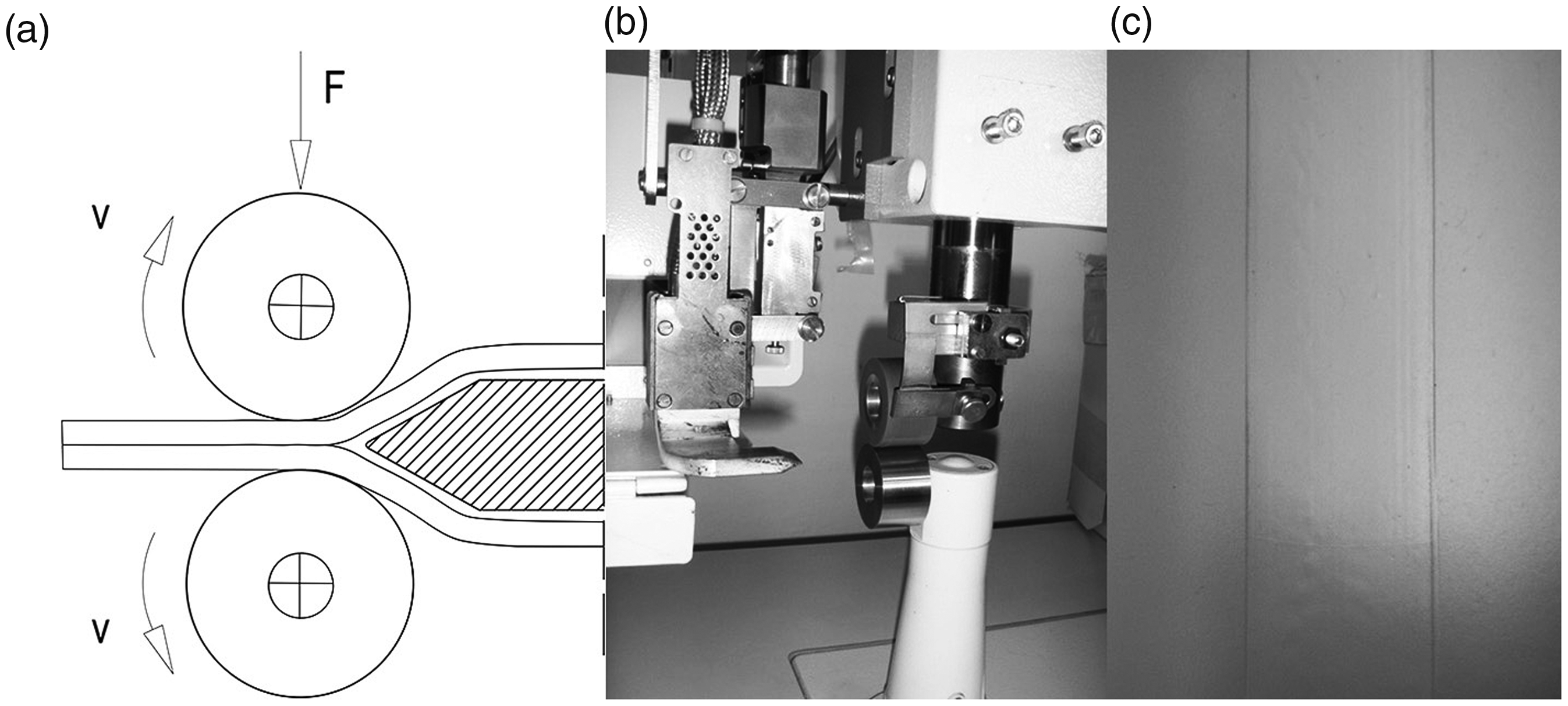
Hot wedge welding of thermoplastic polymer material: (a) schematic presentation of welding; (b) part of the welding machine and (c) appearance of the welded seams.
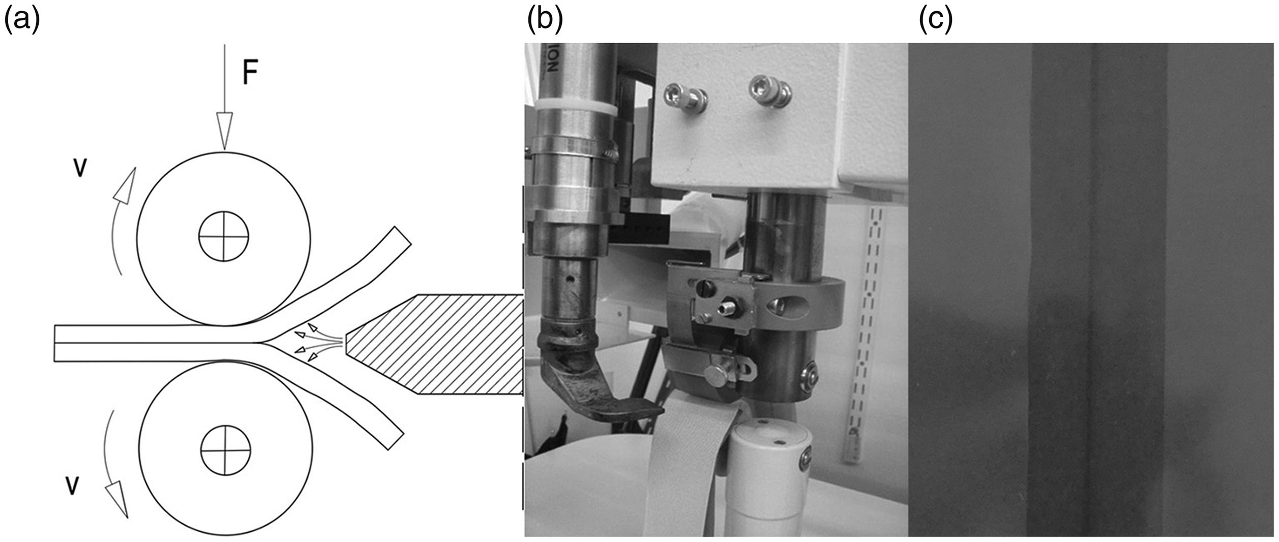
Hot air welding of thermoplastic polymer material: (a) schematic presentation of welding; (b) part of the hot air welding machine and (c) appearance of the welded seams.
Hot wedge welding is a continuous process; the material to be welded is brought into direct contact via the wedge, heated, and then pressed together in the molten state between pressure rollers (Figure 1).
Hot air welding is based on the non-contact heating of the layers of thermoplastic polymer material at the hot air supply point, causing the thermoplastic polymer materials to soften and be welded together due to the action of the pressure force of the rollers (Figure 2). This welding technique is a continuous process and it is most commonly used for welding adhesive tapes on the top of the seams on clothing or other products for technical purposes where watertight and airtight joints are required. 11
The welding parameters that need to be controlled in hot wedge and hot air welding are the temperature (wedge or air), the time of heat exposure, which depends on the welding speed, the contact pressure of the transport rollers, and for hot air welding, the air pressure, on which the speed of the outflowing hot air depends.
Ultrasonic welding
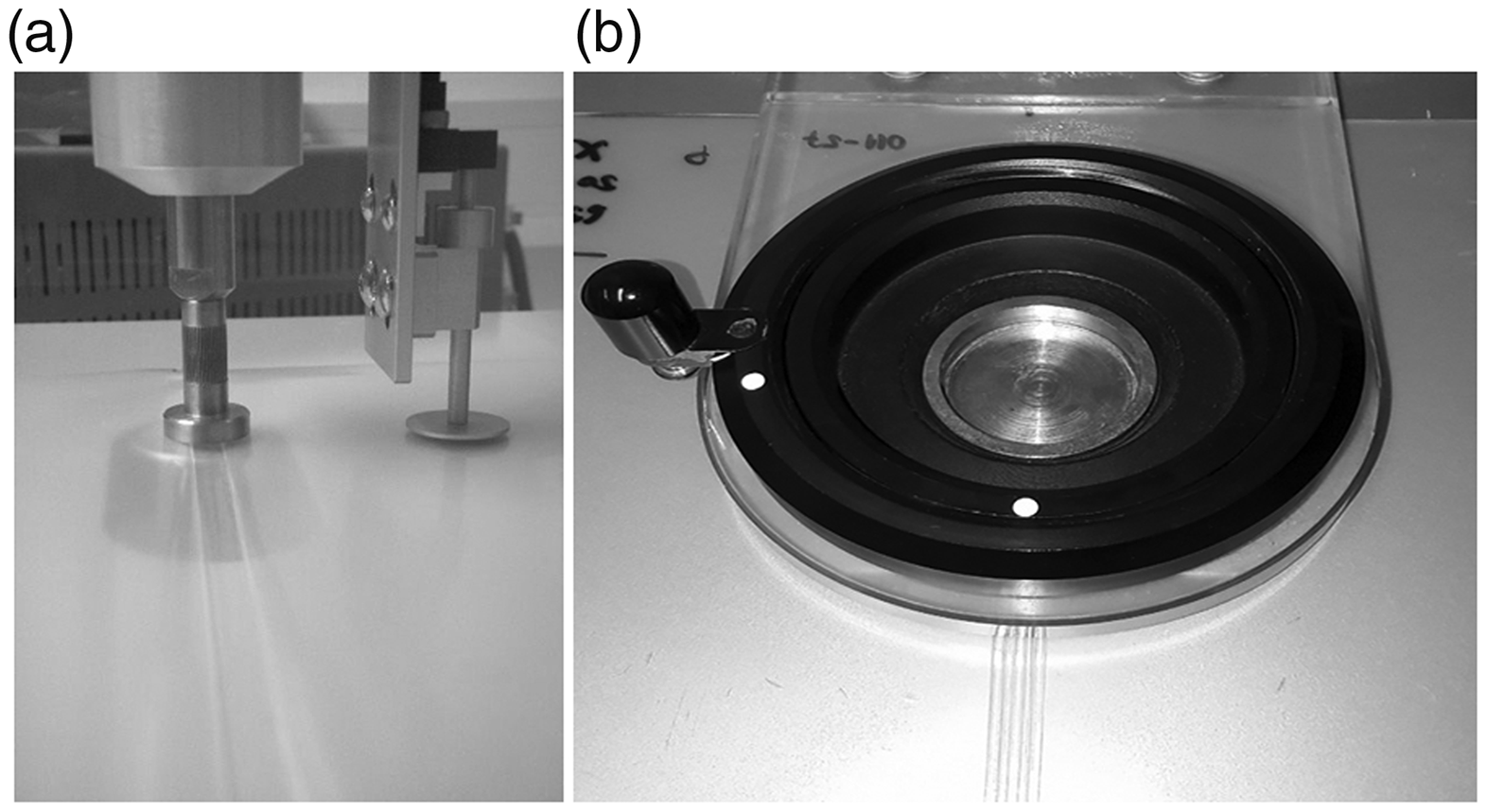
In ultrasonic welding, mechanical vibrations cause the layers of thermoplastic polymer materials to heat up in the weld zone, softening the material and creating a welded seam after cooling. 12 The welded seam appearance depends on the type of counter-roller engraving. 9 Ultrasonic welding machines operate at a frequency of 20–40 kHz, and the amplitude at the tip of the sonotrode ranges from 80 to 100 μm. 3,5 Figure 3 shows the ultrasonic welding technique and part of the ultrasonic machine and welded seam.
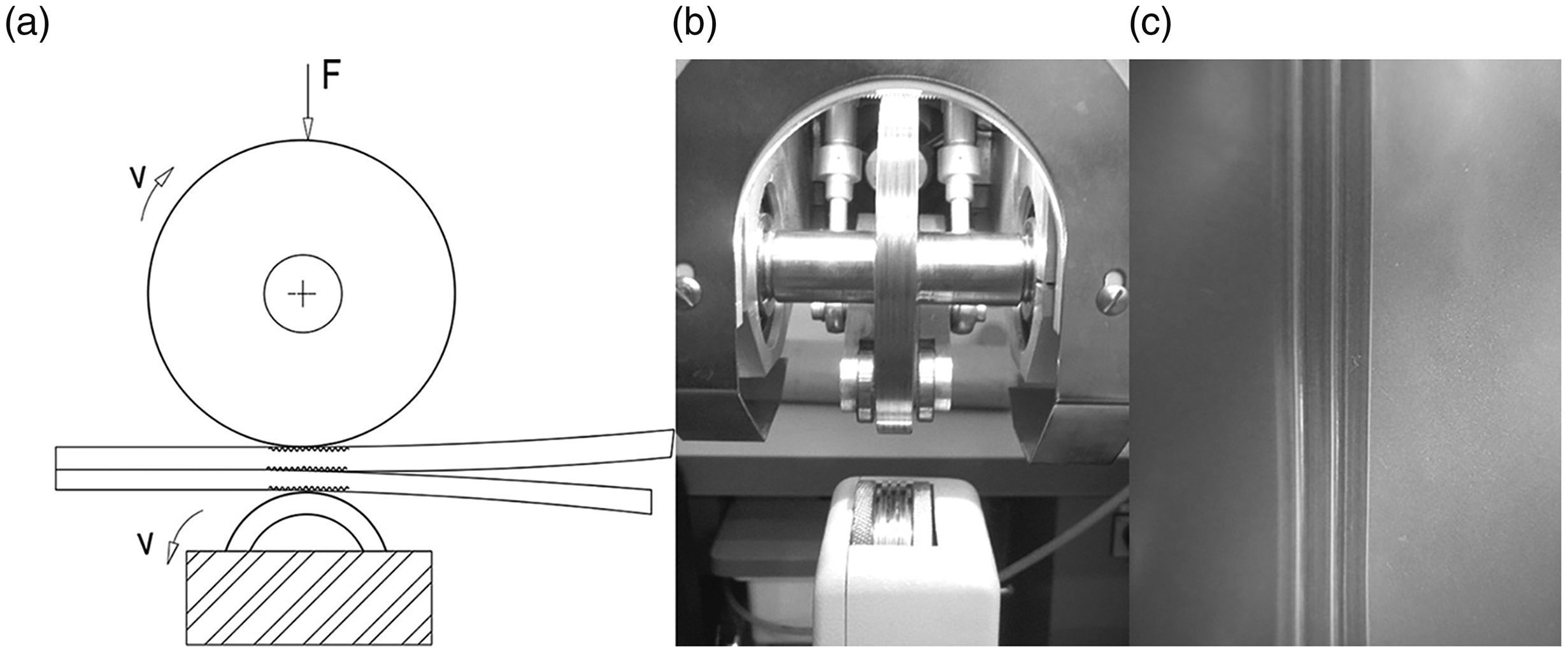
Ultrasonic welding of thermoplastic polymer material: (a) schematic presentation of ultrasonic welding; (b) sonotrode and counter roller of the ultrasonic welding machine and (c) appearance of the welded seams.
The effect of longitudinal mechanical vibrations on thermoplastic polymer material heated to the viscous state required for welding considerably accelerates the diffusion of macromolecules. 13
The parameters of the ultrasonic welding technique are the ultrasonic power, the applied time of the ultrasonic energy, and the pressure of the sonotrode on the material in the weld zone.
High-frequency welding
The HF welding technique is based on the process of internal heating of a thermoplastic polymer material caused by the friction of particles in the electric field between the upper electrode and the lower electrode, which is stimulated by a HF generator operating at a frequency of 27.12 MHz with a power amplifier of 1 kW (Figure 4). It has been found that an approximate power of 50–80 W is required for a welding area of 1 cm2, depending on the type of material and its thickness. 5
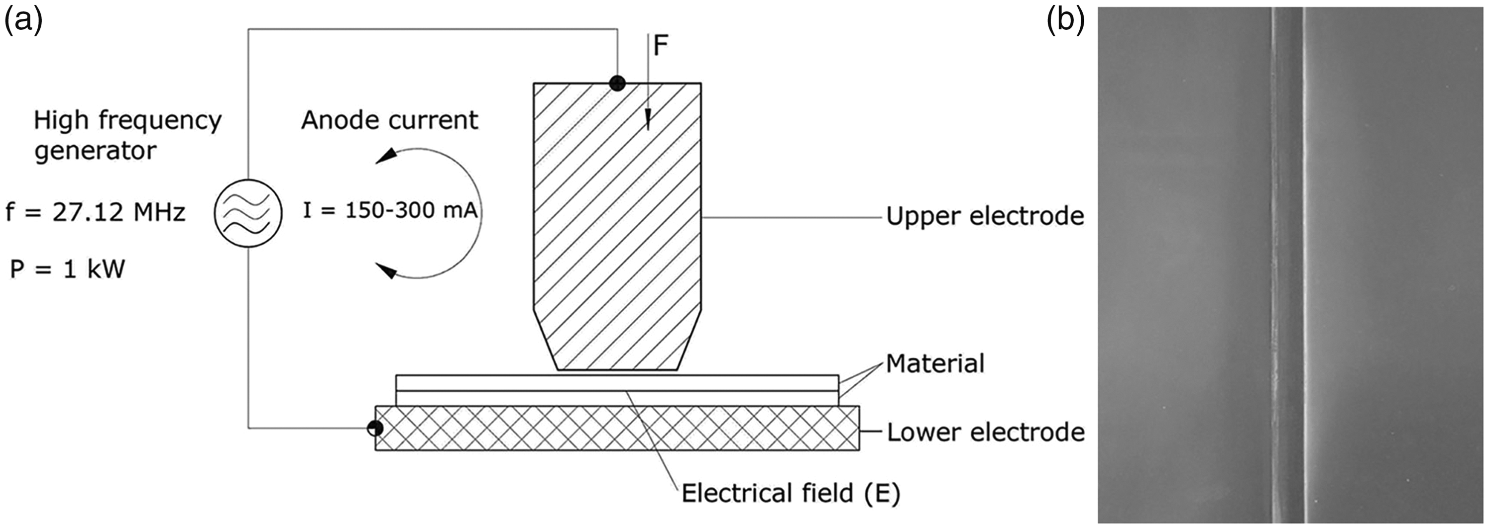
High-frequency welding of thermoplastic polymer material: (a) schematic presentation of high-frequency welding and (b) appearance of the welded seams.
The parameters for HF welding of thermoplastic polymer materials are the anode current, the applied time of the anode current on the thermoplastic polymer material, and the pressure force with which the upper electrode acts on the material. 14 With these welding techniques, several different materials with different thermoplastic properties can be joined in one welded seam. 15
Material and methodology
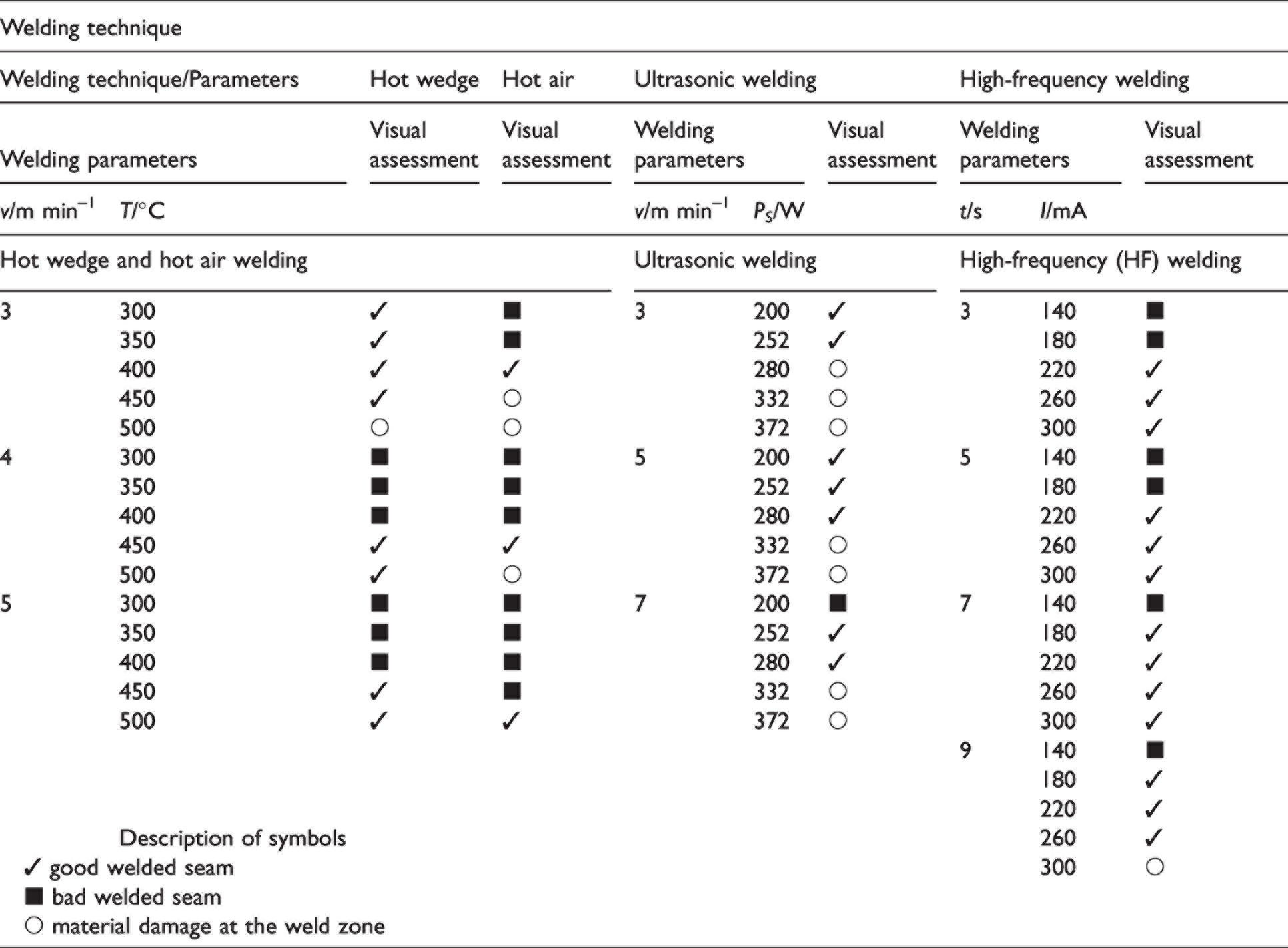
In this work, the welding parameters of the mentioned welding techniques and their influence on the compression properties of the welded seams were studied. In the first phase, thermoplastic polyurethane (TPU) film samples were welded in the manner shown in Figure 5, at defined welding parameters for each welding technique, Table 1, and then in the second phase, the quality of the welded seams was evaluated by visual assessment. Only positively evaluated welded seams were tested for compression properties.
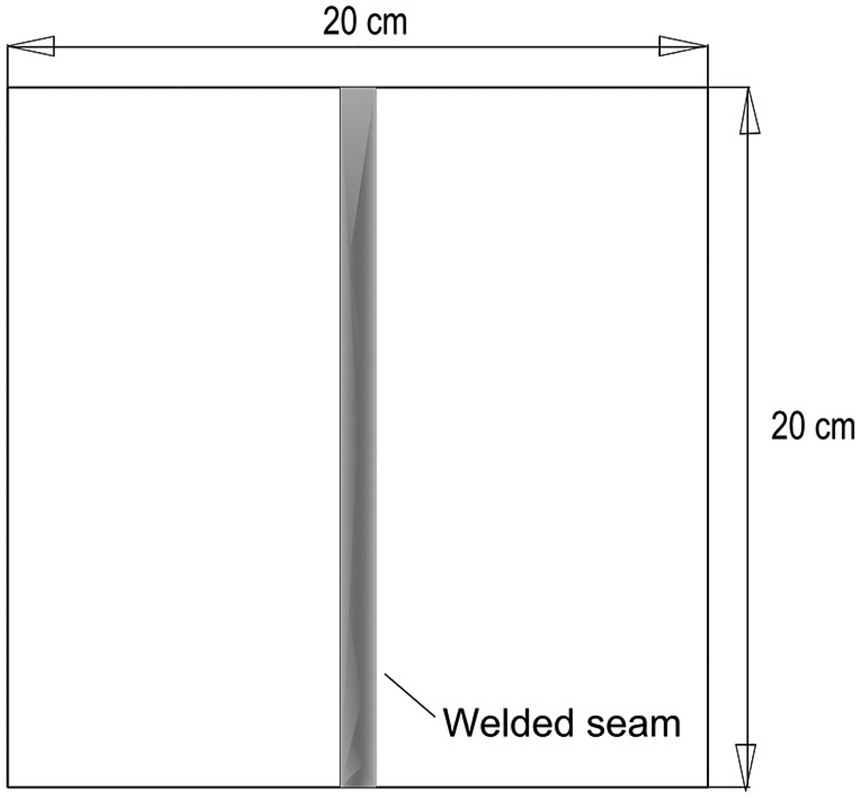
Welded sample for testing compression properties.
Welding parameters used for the individual welding techniques with an assessment of the quality of the appearance of the welded seams produced
Material
Taking into account the welding techniques presented in the introduction part of the experimental work, the welding of TPU film (100% polyurethane) was carried out. The TPU film used has the following characteristics: the thickness 0.77 mm (according to ISO 5084), 16 the mass per unit area is 232 g/m2, (according to ISO 3801), 17 the elongation at rupture is 890%, and the breaking force is 312 N (according to ISO 527-3). 18 The softening temperature is between 140°C and 150°C.
In Table 2 the values of the compression parameters of TPU film measured on the measuring instruments KES-FB3 and FAST-1 are shown for one layer and also for two layers of TPU film. These values were used to compare with the values of compression parameters of the welded seam and without a welded seam.
The compression parameters of the used thermoplastic polyurethane (TPU) film
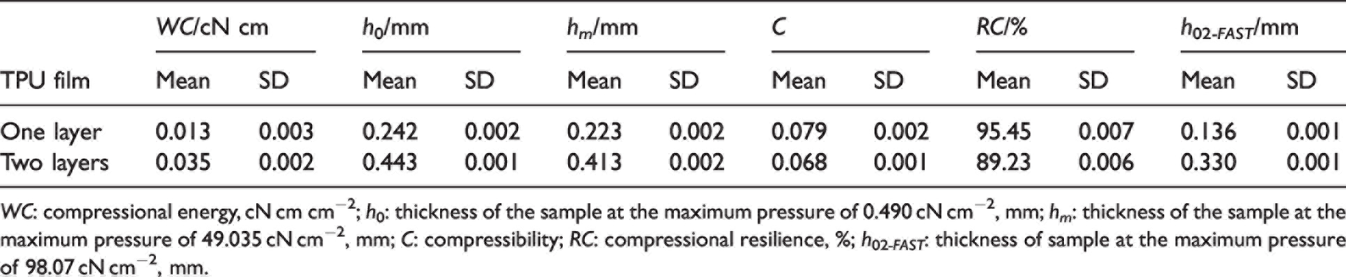
WC: compressional energy, cN cm cm−2; h0: thickness of the sample at the maximum pressure of 0.490 cN cm−2, mm; hm: thickness of the sample at the maximum pressure of 49.035 cN cm−2, mm; C: compressibility; RC: compressional resilience, %; h02 -FAST : thickness of sample at the maximum pressure of 98.07 cN cm−2, mm.
For this purpose, samples of 200 mm × 200 mm TPU film were cut, which were welded in two layers, Figure 5, with different welding process parameters for each welding technique presented in Table 1.
Welding machines used and technical characteristics
The machines used to weld the thermoplastic material samples are divided according to the welding technique.
Pfaff 8304-020 was used for hot wedge and hot air welding with the possibility to replace the heating element (hot wedge, Figure 1(b), or the hot air nozzle, Figure 2(b)). In the case of hot wedge welding, the welding power is 1 kW and the maximum welding temperature is up to 550°C. In the case of hot air welding, the power is 3 kW and the maximum welding temperature is up to 650°C. Welding speed ranges from 0 to 10 m min–1, a puller feed system is used for feeding the material, and the welded seam width is 20 mm. A Pfaff Seamsonic 8310-003 was used to weld with the ultrasonic welding technique. The ultrasonic welding machine operates with an ultrasonic generator power of 400 W and at a frequency of 35 kHz. The sonotrode, made of an alloy of aluminum and titanium, transmits ultrasonic vibrations to the material during welding. The width of the sonotrode is 10 mm and the force of its pressure on the material in the weld zone is 0–800 N. For welding, the lower counter roller has the task of transporting the material. 19 The samples were welded using a three-line pattern on the 8 mm wide engraved counter roller (Figure 3(b)).
The HF Siatem welding machine, which operates at a frequency of 27.12 MHz with a power amplifier of up to 1 kW, was used to produce samples using the HF welding process. The shape of the welded seam depends on the shape of the upper HF electrode. 5 The upper HF electrode with a length of 190 mm and a width of 6 mm was used to produce samples of welded seams.
Methodology
In the second part of the experimental work, the visual assessment of the welded seam was compared to the appearance of the weld, where the emphasis was on the extruded edges, Figures 6(a) and (b), and the bulk of the material along the weld zone. Only samples that showed the appropriate quality according to the visual assessment were used to test the compression properties (Table 1).
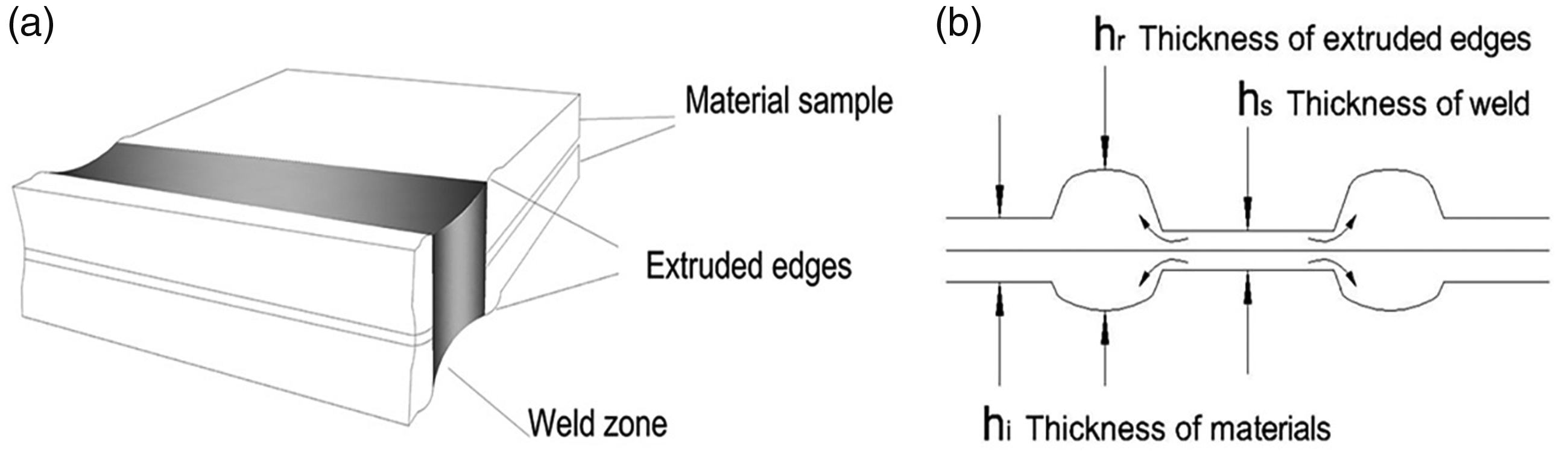
Schematic presentation of the welded seam: (a) appearance of a welded seam consisting of two material layers and (b) cross-section of the welded seam showing the characteristic of welded seam thicknesses: the thickness of the extruded edges (hr), the thickness in the weld zone (hs), and the thickness of the material outside the weld zone (hi).
Evaluations of the welded seams obtained by applying individual welding techniques depending on the welding parameters applied are shown in Table 1. The individual scores are shown using the symbols given in the table legend, and Figure 7 gives an example of the welded seam appearance and the evaluation of the welded seams.
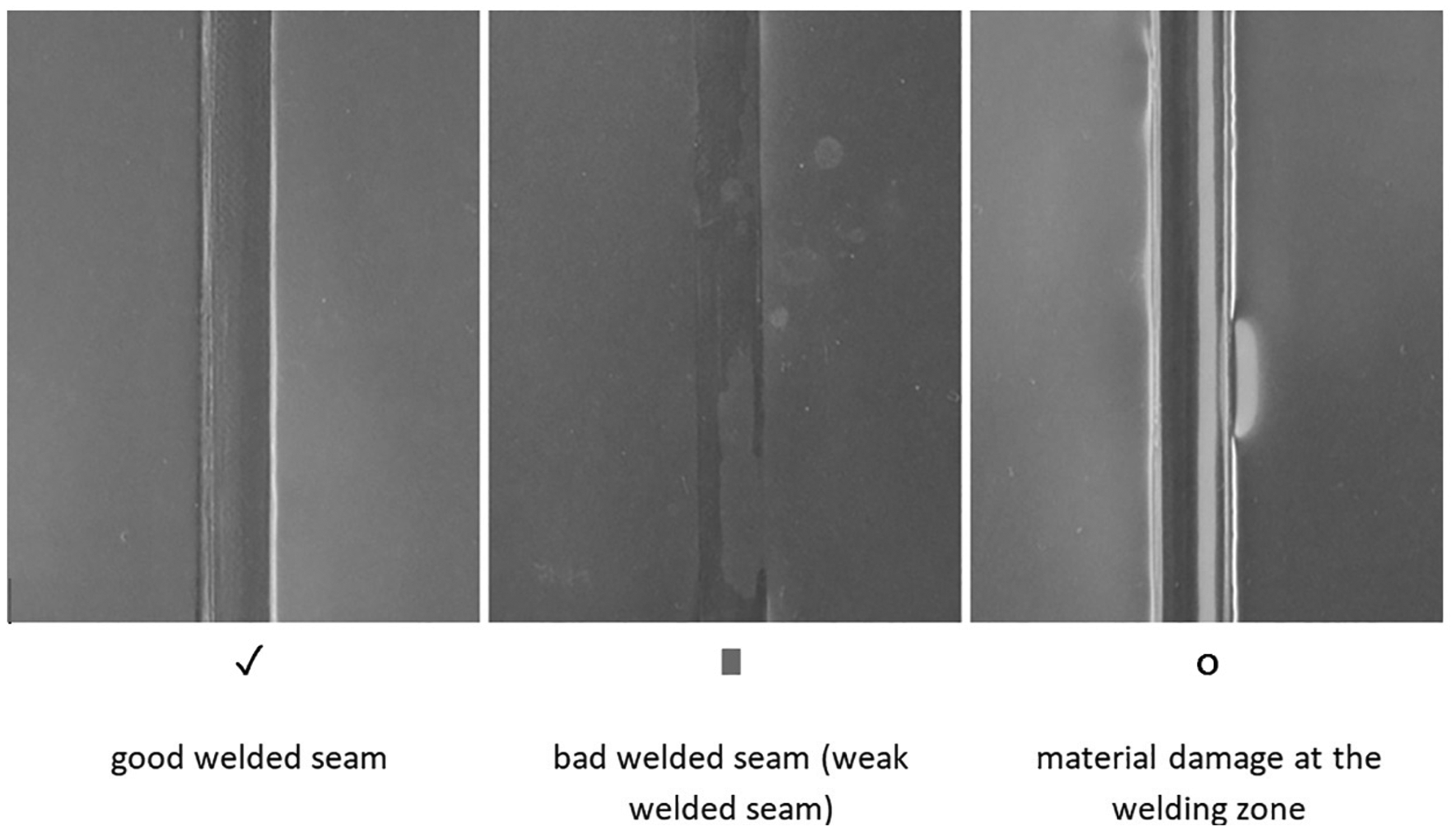
Presentation of welded seams assigned to the visual assessment.
Evaluation of the compression properties of welded seams
The testing of the compression properties of the analyzed samples was carried out to investigate the influence of the welding parameters of the TPU film on the change of the compression properties of the TPU film in the weld zone of two material layers.
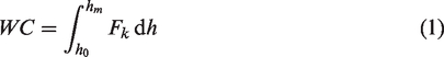
The compression properties were tested regarding the obtained structure of the welded seams using the KES-FB3 and the FAST-1 measurement instruments (Figure 8).
Presentation of measuring the compression properties of welded seams using the measurement instruments: (a) KES-FB 3 and (b) FAST-1.
The measurement values for each type of sample are obtained as the average values of three measurements. The testing of compression properties with the KES-FB3 measuring instrument is based on the testing of the compression deformation of the sample, which is subjected to a maximum pressure of 49.035 cN cm−2. The samples were compressed by a circular plate of steel whose area is 2 cm2, acting perpendicular to the surface at a constant velocity of compression of 0.2 mm/s. The characteristic parameters of the compression properties are compressional energy WC, linearity LC, compressional resilience RC, the thickness h0 of the sample at a maximum pressure of 0.49 cN cm−2, and the thickness hm at a maximum pressure of 49.035 cN cm−2.
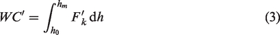
Compressional energy WC represents the energy required for compression deformation and is calculated according to the expression
20
Compressional energy WC is a measure of fabric compressibility and is closely related to its thickness. The values of compressional energy are reflected in touch. Higher values of compressional energy WC give a fuller hand and lower values give a slightly stiffer feel of the welded seams at the measuring point.
Compressional resilience RC maintains the ratio between the energy released or reversed during relaxation and the energy absorbed during compression and is determined by expression
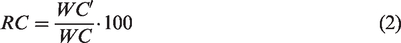
The RC parameter reflects the capability of the material to recover under compression relief and is a measure of its volume flexibility. Higher values of resilience RC give a feeling of elasticity and have a positive effect on the value of overall touch, resulting in a fuller and softer touch, while lower RC parameter values indicate a stiffer and smoother welded seam touch. 20
The compressibility C, which reflects the ratio between the change in thickness (h0–hm) of the welded seam and the thickness h0, is determined by Equation (4)
21
Higher values of compressibility C were found in welded seams with a greater difference between the thicknesses h0 and hm, that is, in welded seams that have noticeably extruded edges. Lower values of compressibility C were found in welded seams that feel stiffer and smoother and do not have highly extruded edges.
The testing of compression properties with the FAST-1 measurement system is based on the determination of the compression deformation of welded seams subjected to a compression of 98.07 cN cm−2 (h02 -FAST values). Since the sample is subjected to compression pressure in the effective surface area of 10 cm2, Figure 8(b)), it can be assumed that the values of change in the thickness obtained refer to the values of the thickness of the extruded edge (values hr according to Figure 6(b)).
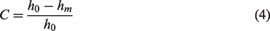
According to the different welding techniques and the resulting different weld widths (the width of the welded seam obtained with hot wedge and hot air welding is 20 mm, with the ultrasonic welding technique it is 9 mm, and with the HF welding technique it is 7 mm), the measuring area varies when determining the compressional properties using the KES-FB3 instrument. Measurement of compression properties with the KES-FB3 instrument in the case of welded seams obtained by ultrasonic and HF welding techniques refers to the measurement of compression properties in the area of the welded seam, Figure 9, while in the case of hot wedge and hot air welding technique, the measuring range also occupies the area of the extruded edges.
Presentation of the measuring body of the KES-FB3 measurement instrument when measuring the compression properties and the welded seam width made using the ultrasonic welding technique.
Results and discussion
The results of the compression properties of the welded seams obtained using the four welding techniques at different welding parameters are shown in Figures 10 –13. The thickness of the welded seam measured at various compression pressure using the KES-FB3 instrument was thickness h0 at a maximum pressure of 0.49 cN cm−2 and thickness hm at a maximum pressure of 49.035 cN cm−2. The thickness h02 -FAST was measured using the FAST-1 measurement instrument at a maximum pressure of 98.07 cN cm−2.
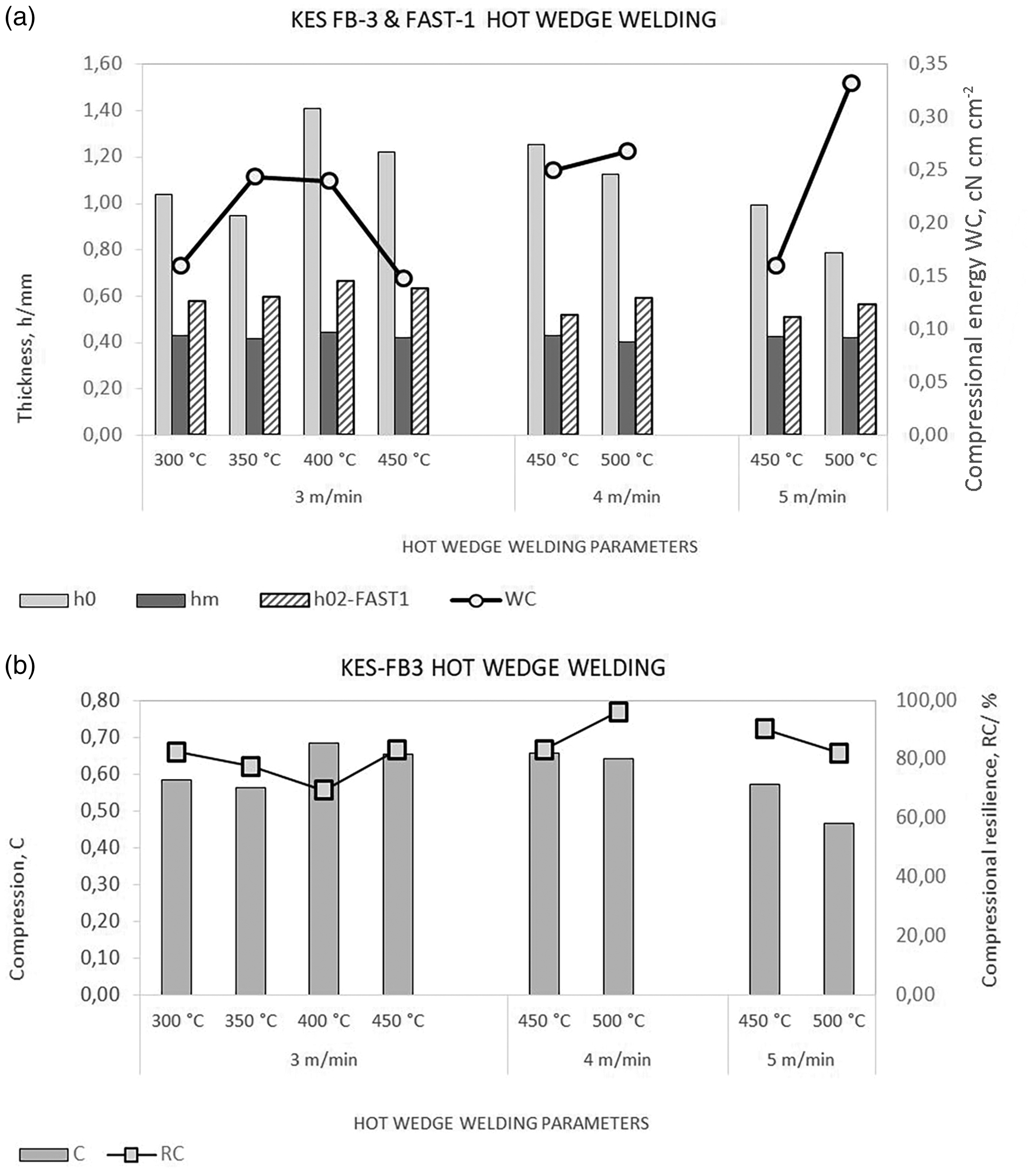
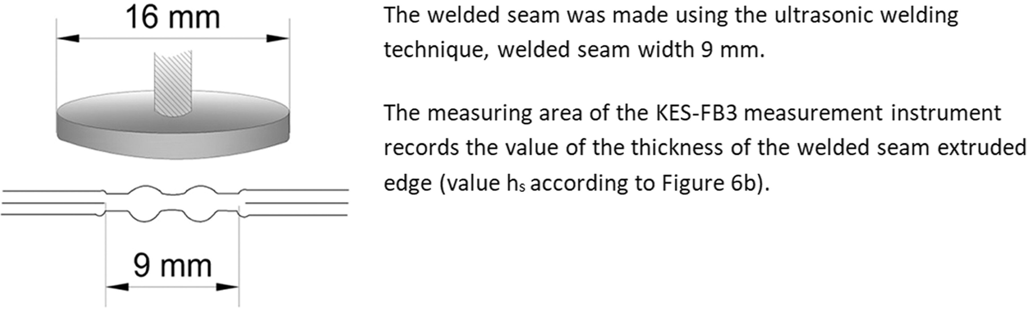
Compression properties of hot wedge welded seams as a function of temperature and welding speed: (a) compressional energy WC and thicknesses h0, hm, and h02 -FAST in the weld zone and (b) compressibility C and compressional resilience RC in the weld zone.
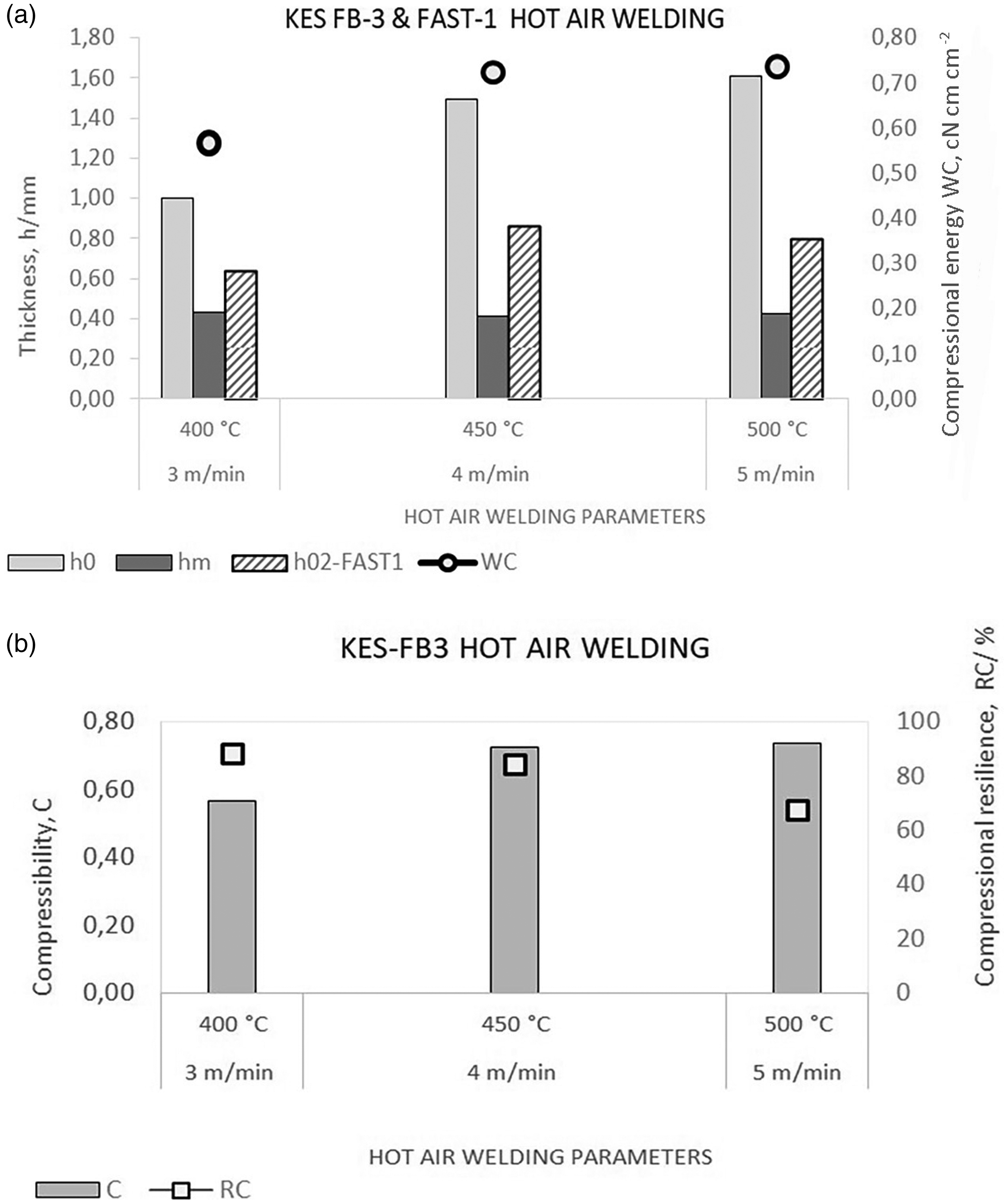
Compression properties of hot air welded seams as a function of hot air temperature and welding speed: (a) compressional energy WC and thicknesses h0, hm, and h02 -FAST in the weld zone and (b) compressibility C and compressional resilience RC in the weld zone.
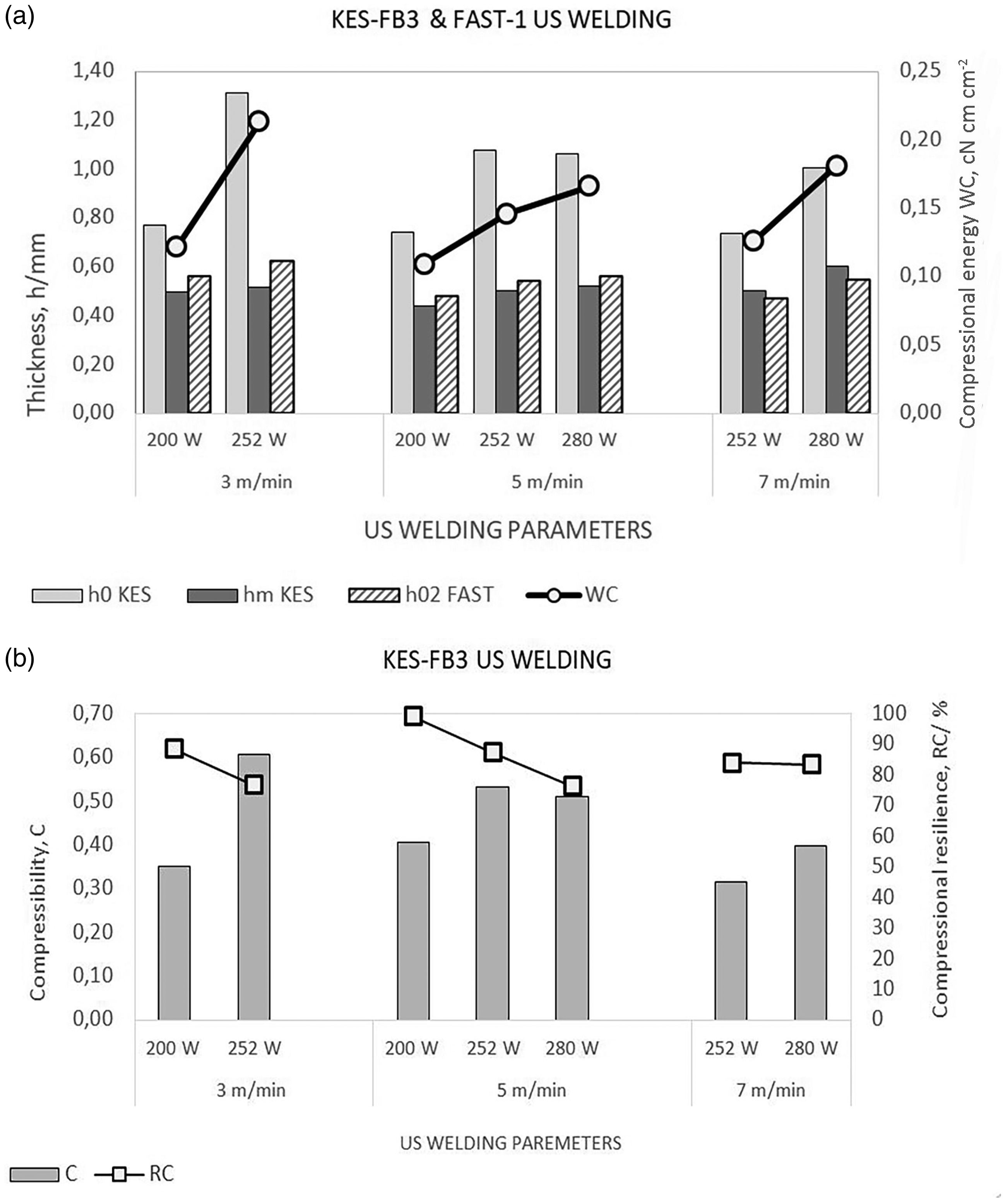
Compression properties of welded seams made by the ultrasonic welding technique depending on the ultrasonic power and welding speed: (a) compressional energy WC and thicknesses h0, hm, and h02 -FAST in the weld zone and (b) compressibility C and compressional resilience RC in the weld zone.
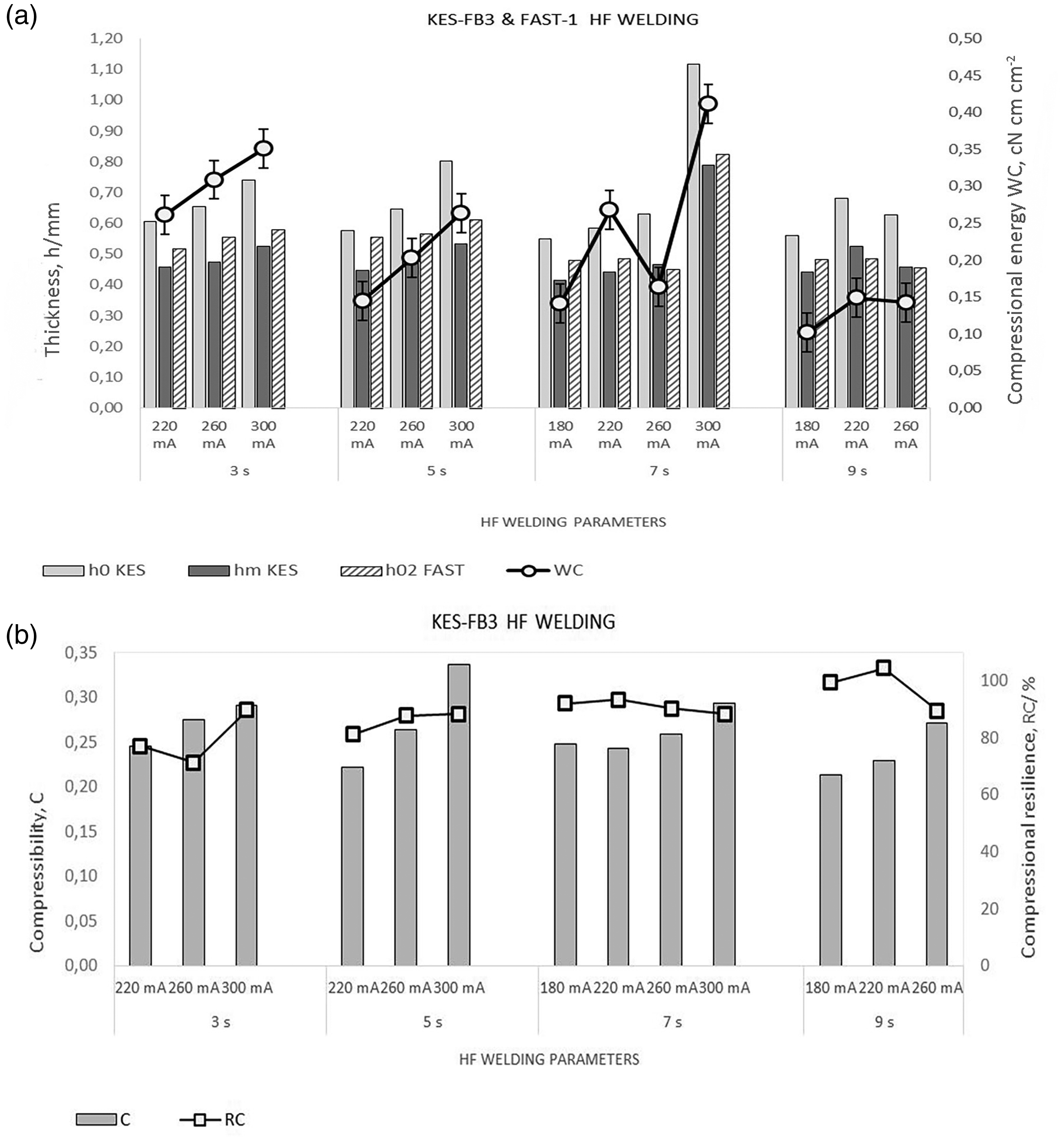
Compression properties of welded seams made using the high-frequency (HF) welding technique depending on the values of the anode current and welding time: (a) compressional energy WC and thicknesses h0, hm, and h02 -FAST in the weld zone and (b) compressibility C and compressional resilience RC in the weld zone.
Analysis of evaluation of the visual quality of the welded seams
Experimental tests of the compression properties of the welded seams were performed only on specimens with proper quality of the welded seams, according to the criteria listed in Table 1. The influence of welding parameters and their values is reflected in the quality and properties of the welded seams, and thus in the compression properties.
From the evaluation of the visual quality of the welded seams achieved by welding with the hot wedge technique using different welding parameters, Table 1, it can be seen that at lower welding temperatures of the wedge at higher welding speeds (correspondingly shorter heat exposure time), an unfavorable or weak welded seam is produced, while a good quality of the welded seam was achieved at a welding temperature of 400–450°C and a welding speed of 3 m min−1 at a temperature of 450°C and a welding speed of 4 m min−1, while heat damage is already visible at a temperature of 500°C.
A similar tendency is seen in the case of the samples that were welded using a hot wedge, but the applied temperature was higher by about 50°C, according to Table 1, which can be attributed to the non-contact effect of temperature on the TPU film. It can be seen that a good quality of the welded seam is achieved at a welding speed of 3 m min−1 and a welding temperature of 400°C, as well as at welding speeds of 4 and 5 m min−1 and welding temperatures of 450–500°C.
From the evaluation of the welded seams achieved by welding with the ultrasonic technique and different welding parameters (Table 1), it can be seen that using a higher ultrasonic generator power, that is, from 332 to 372 W and a lower welding speed (corresponding to a longer sonotrode vibration effect on the material) produces welded seams with visible damage or excessively extruded edges that affect the welded seam quality and properties. The proper quality of the welded seam was obtained at welding speeds of 3 and 5 m min−1 and ultrasonic welding power from 200 to 280 W, and at the welding speed of 7 m min−1 and ultrasonic generator power from 252 to 280 W.
Analysis of welded seams made using the HF welding technique shows that proper quality of welded seams was obtained at higher values of anode current and shorter welding time and at lower values of anode current and longer welding time. At a welding time of 9 s and an anode current of 300 mA, the material is damaged in the weld zone. A proper quality of the welded seams is achieved at welding times of 3 and 5 s and an anode current from 220 to 300 mA, and also at a welding time of 7 s and a wide range of anode current values from 180 to 300 mA, as well as at a welding time of 9 s but slightly lower anode current values from 180 to 260 mA.
Analysis of results of compression properties of the welded seams
Due to the different welded seam widths, the values of individual compression parameters refer to different measurement areas, according to Figure 6(b). For welded seams made by welding with a hot wedge and hot air, values of the parameters of the compression properties WC, h0, hm, C, and RC refer to testing the welded seam thickness, while the values of h02 -FAST refer to the thickness of the extruded edge. For welded seams formed by ultrasonic and HF welding techniques, values of the parameters of the compression properties WC, h0, hm, h02 -FAST , C, and RC refer to testing the thickness of the extruded edge.
The compression parameters WC, h0, hm, h02 -FAST , C, and RC and welding parameters were analyzed by using the analysis of variance (ANOVA) two-factor statistical method. Statistical analysis provided information on the existence of a relationship between two independent (welding parameters) and one dependent variable (compression parameters). The observed welding parameters in the hot air and hot wedge welding techniques are the welding speed and the temperature. In ultrasonic welding, was observe the influence of the welding parameters ultrasonic power and welding speed, and in the case of HF welding the influence of welding parameters anode current and welding time.
Analysis of compression properties of the welded seams made using the hot wedge welding technique
The compression parameters and hot wedge welding parameters were analyzed using the ANOVA two-factor statistical method, and the results are shown in Table 3.
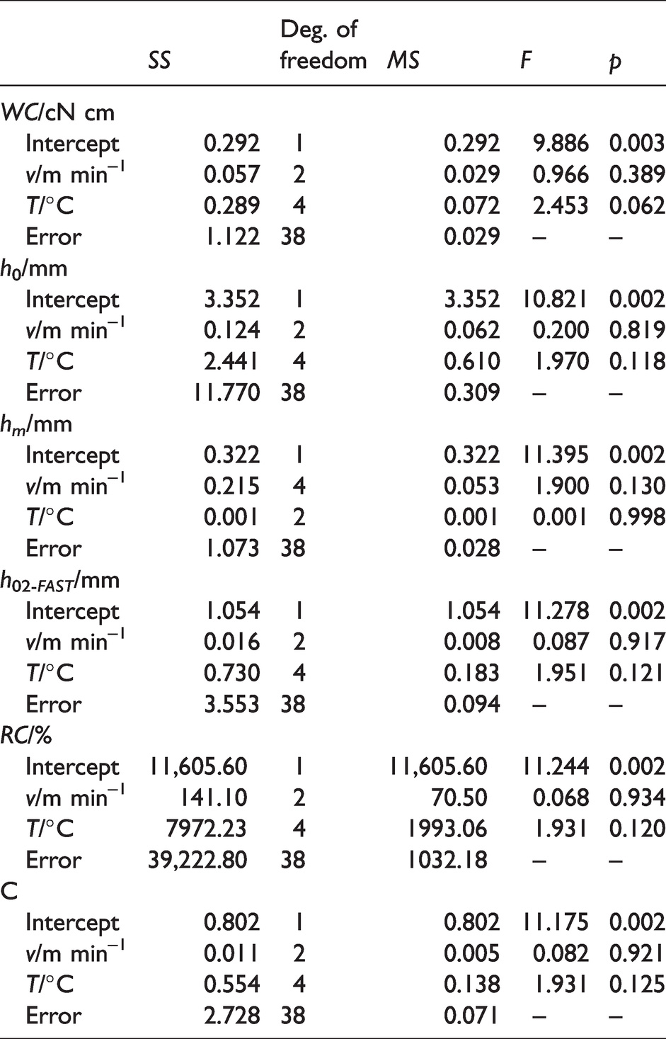
Statistical analysis of the relationship between the compressional parameters (WC, h0, hm, h02 -FAST , C, and RC) and hot wedge welding parameters (welding speed v/m min−1 and welding temperature T/°C)
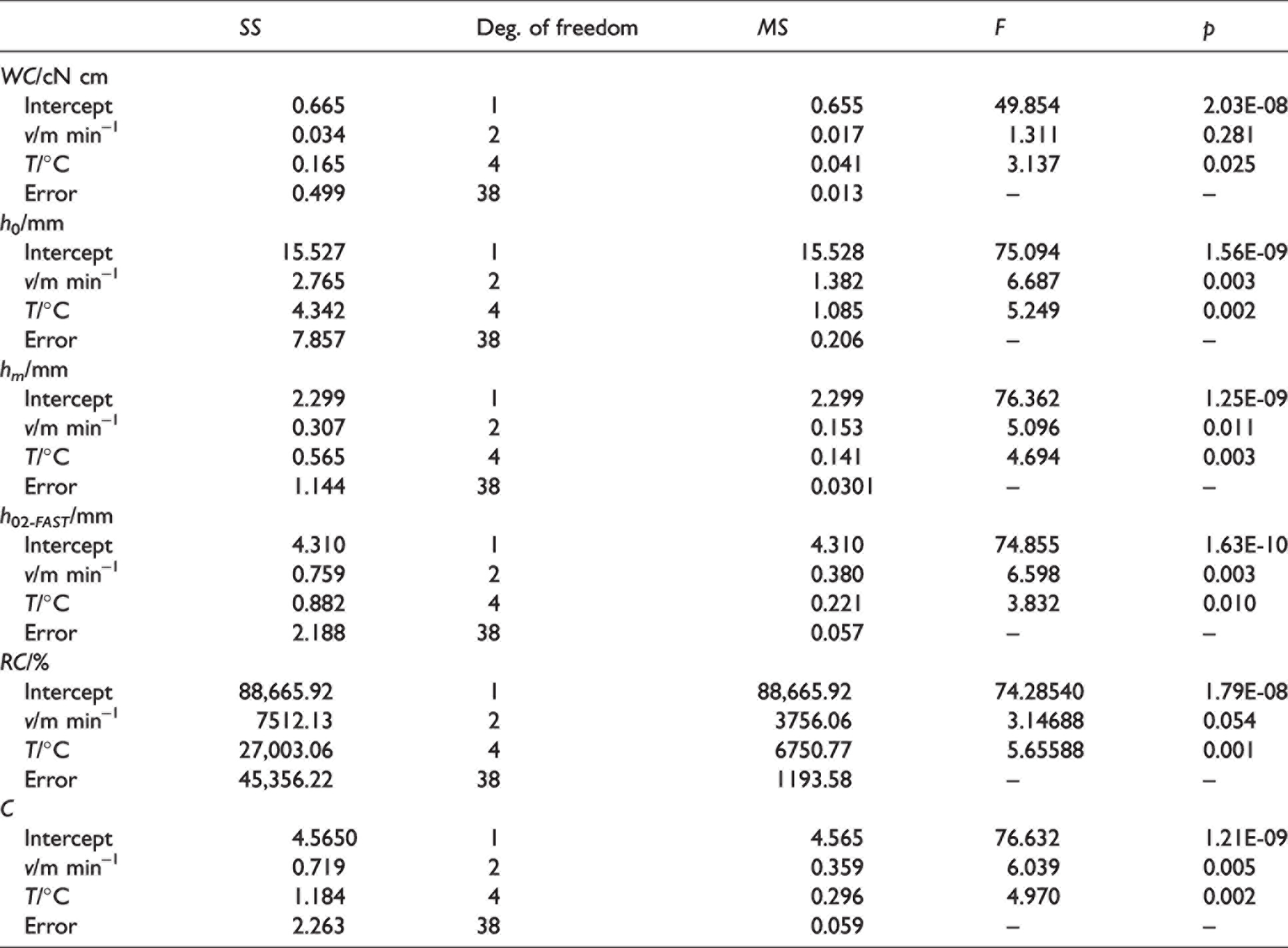
An effect of the relationship between the dependent variable (separately for each compressional parameter (WC, h0, hm, h02 -FAST , C, and RC)) and the two independent variables, welding speed v/m min−1 and welding temperature T/°C, are presented in Table 3. F-tests and p-values at the significance level α = 0.05 showed there was a significant interaction effect between welding speed and welding temperature on all compressional parameters. The main effects analysis showed that welding speed did not have a statistically significant effect on compressional energy WC (p = 0.281), and the second independent variable, welding temperature, did have a statistically significant effect on compressional energy WC (p = 0.010). The main effects analysis for thickness h0 showed that welding speed did have a statistically significant effect on thickness h0 (p = 0.003), and the same effect with welding temperature (p = 0.002). The interaction effect of welding parameters on thickness hm showed that both welding parameters, welding speed (p = 0.011) and welding temperature (p = 0.003), did have a statistically significant effect. The main effects analysis showed that welding speed (p = 0.003) and welding temperature (p = 0.010) did have a statistically significant effect on thickness h02 -FAST at the significance level α = 0.05.
Statistical analysis showed that welding speed did not have a significant effect on the compressional resilience RC (p = 0.054), and the second independent variable, welding temperature, did have a statistically significant effect on the compressional resilience RC (p = 0.001). An effect of the relationship between both welding parameters, welding speed (p = 0.005) and welding temperature (p = 0.002), did have a statistically significant effect on compressibility C. The results of thicknesses h0, hm, h02 -FAST , and compressional energy WC are presented in Figure 10(a), and values of compressional resilience RC and compressibility C are presented in Figure 10(b). Figure 10(a) shows that increasing the welding temperature at all welding speeds increases the thickness of the extruded edge (thickness h02 -FAST ) and reduces the welded seams thicknesses h0 and hm. Greater changes in the welded seam thickness resulting from higher values of the welding temperature exposure on the material to the hot wedge can be attributed to greater deformation of the TPU film in the weld zone. The more softened thermoplastic polymer material can be more easily extruded from the weld zone into the welded seam edge due to the effect of the roller compression force, which is reflected in the decreased welded seam thickness (hs according to Figure 6(b)) and the increased values of the thickness of the extruded edge, as the thickness values h02 -FAST show. The lowest values of thickness of the extruded edge h02 -FAST were measured on welded seams at a higher welding speed of 5 m min−1 and a temperature of 450°C, and the values are about 34% greater than the thickness of the two layers of material. The highest values of the thickness of the extruded edge h02 -FAST were measured on samples of welded seams welded at a minimum welding speed of 3 m min−1 and a temperature of 400°C, and these values are about 50% greater than the thickness of the two layers of material (Table 2). At the same welding parameters, the highest value of the compressional energy WC is measured. Higher values of compressional energy WC are attributed to welded seams, which give a feeling of fullness and voluminosity when touched. In Figure 10(b), the results of the compressional resilience RC of the welded seams show higher values at higher welding temperatures (450°C). By increasing the welding speed (i.e. by shortening the heat time) and the welding temperature, the resulting welded seams have lower compressibility values C.
Analysis of compression properties of the welded seams made using the hot air welding technique
An effect of the relationship between compression parameters and hot air welding parameters was analyzed by using the ANOVA two-factor statistical method, and the results are shown in Table 4.
Statistical analysis of the relationship between the compressional parameters (WC, h0, hm, h02 -FAST , C, and RC) and hot air welding parameters (welding speed v/m min−1 and welding temperature T/°C)
The relationship between the dependent variable (separately for each compressional parameter (WC, h0, hm, h02 -FAST , C, and RC)) and welding parameters, welding speed v/m min−1 and welding temperature T/°C, are presented. F-tests and p-values at the significance level α = 0.05 showed there was a significant interaction effect between welding speed and welding temperature on compressional parameters. The main effects analysis showed that welding speed did not have a statistically significant effect on compressional energy WC (p = 0.389), and the same with the second welding parameter, welding temperature, which also did not have a statistically significant effect on compressional energy WC (p = 0.062). Very similar results were obtained by analyzing the interaction effect between welding parameters, welding speed and welding temperature, on other compressional parameters (h0, hm, h02 -FAST , C, and RC). The main effects analysis showed that welding speed and welding temperature did not have a statistically significant effect on any of the compressional parameters (h0, hm, h02 -FAST , C, and RC). According to the results of statistical analysis, it can be seen that only a change in welding temperature or welding speed does not have a significant effect on the compression parameters.
The results of the parameters of compression properties, such as compressional energy WC and the welded seam thicknesses h0, hm, and h02 -FAST , obtained with different welding parameters using the hot air welding technique are shown in Figure 11(a). The result reveals that increasing the welding temperature causes an increase in the welded seam thickness h0 and compressional energy WC. The lowest values of thickness h02 -FAST (refers to the thickness of the extruded edge of the welded seam) was measured on a sample of the welded seams at a speed of 3 m min−1 and a temperature of 400°C, and the values are about 48% greater than the thickness of the two layers of material (Table 2). The highest values of the thickness of the extruded edge h02 -FAST were measured at a welding speed of 4 m min−1 and a temperature of 450°C, and the values are about 61% greater than the thickness of the two layers of material. The results show, in Figure 11(b), that by increasing the welding temperature, the welded seams show higher compressibility values C and lower compressional resilience RC values.
Analysis of compression properties of the welded seams made using the ultrasonic welding technique
The compression parameters and ultrasonic welding parameters were analyzed by using the ANOVA two-factor statistical method, and the results are shown in Table 5.
Statistical analysis of the relationship between the compressional parameters (WC, h0, hm, h02 -FAST , C, and RC) and ultrasonic welding parameters (welding speed v/m min−1 and ultrasonic power Ps/W)
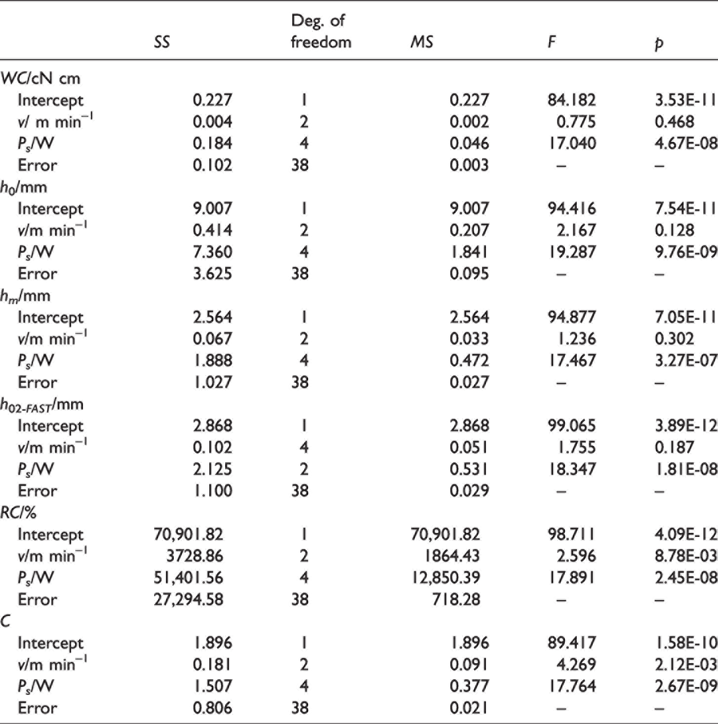
A two-factor ANOVA revealed that there was a statistically significant interaction between the effects of welding speed and ultrasonic power on all compressional parameters (WC, h0, hm, h02 -FAST , C, and RC) at the significance level α = 0.05 (F-test and p-value). The main effects analysis showed that welding speed did not have a statistically significant effect on compressional energy WC (p = 0.468), but the second independent variable, ultrasonic power, did have a significant interaction effect on compressional energy WC (p = 4.67E-08). The same results of the main effects analysis showed that welding speed did not significantly affect thicknesses (h0, hm, and h02 -FAST (p > 0.005)), but the second independent variable, ultrasonic power, did have a statistically significant effect on thicknesses h0 (p = 4.67E-08), hm (p = 3.27E-07), and h02 -FAST (p = 1.81E-08). The interaction effect of welding parameters on compressional resilience RC and compressibility C showed that both welding parameters (welding speed and ultrasonic power) did have a statistically significant effect (p < 0.05).
The results of compressional energy WC and the welded seams thicknesses h0, hm, and h02 -FAST made with different welding parameters using the ultrasonic welding technique are presented in Figure 12(a). The results show that by increasing the power of ultrasonic welding, the values of compressional energy WC and thicknesses h0, hm, and h02 -FAST increase. Higher values of compressional energy WC are attributed to the welded seams, which give the feeling of fullness and voluminosity when touched. Samples of welded seams that were visually positively evaluated did not have expressed extruded edges (hr according to Figure 6(b)), and the results of measuring the thickness hm relating to the welded seams and the weld zone is about 17% greater than the thickness hm measured on two layers of material (Table 2). These welded seam samples were welded at lower ultrasonic welding power of 200 W. The welded seams that have expressed extruded edges were welded at a higher ultrasonic welding power of 280 W, and the welding seam thickness hm is about 31% greater than the thickness of the two layers of material. The result of compressibility C and compressional resilience RC for welded seams is presented in Figure 12(b). It can be seen that by increasing the welding speed and the ultrasonic power during ultrasonic welding, the welded seams show lower values of compressibility C of the observed welded seams. The results of compressional resilience RC show that by increasing the speed and the power during ultrasonic welding, the welded seams show lower values of compressional resilience RC, except at a welding speed of 7 m min−1 where RC values are approximately the same. The lower values of compressional resilience RC give a stiffness touch and such welded seams have excessively extruded edges, which affect the welded seams quality.
Analysis of compression properties of the welded seams made using the high-frequency welding technique (HF)
A two-factor ANOVA was performed to analyze the effect of welding time, t/s, and anode current, I/mA, on compressional parameters, and the results are shown in Table 6.
Statistical analysis of the relationship between the compressional parameters (WC, h0, hm, h02 -FAST , C, and RC) and high-frequency welding parameters (welding time t/s and anode current I/mA)

F-test and p-values at the significance level α = 0.05 showed there was a significant interaction effect between welding time and anode current on all compressional parameters, WC, h0, hm, h02 -FAST , C, and RC. The main effects analysis showed that welding time did have a statistically significant effect on compressional energy WC (p = 2.73E-03), and the second independent variable, anode current, also did have a statistically significant main effect on compressional energy WC (p = 7.05E-06). The main effects analysis showed that welding time did not have a statistically significant effect on thicknesses h0, hm, and h02 -FAST (p > 0.05), but the second independent variable, anode current, did have a statistically significant main effect on thicknesses h0 (p = 0.001), hm (p = 0.001), and h02 -FAST (p = 0.003). The same results of the main effects analysis showed that welding time did not significantly affect compressional resilience RC and compressibility C, but the second independent variable, anode current, did have a statistically significant main effect on compressional resilience RC (p = 0.008) and compressibility C (p = 0.003).
The results of the parameters of compression properties, such as compressional energy WC and the welded seam thicknesses h0, hm, and h02 -FAST , obtained with different HF welding parameters are shown in Figure 13(a). The values of the compressional energy WC increase with the increase of the anode current at all welding times. The values of compressional energy WC are higher at the welding time of 3 s than at the welding time of 9 s. Lower values of compressional energy are attributed to welded seams that are stiffer to the touch and give less fullness when touched, which can be attributed to too long exposure to high values of anode current as a result of material damage. These welded seams have a slightly wider and irregular edge. The analysis of the results shows that by increasing the strength of the anode current from 220 to 300 mA, the thicknesses h0, hm, and h02 -FAST increase. The samples of welded seams welded at high values of anode current of 260 and 300 mA have more pronounced extruded edges. The measured values of the thickness of the extruded edges hm are about 47% higher than those of the thickness hm measured for two layers of TPU film (Table 2). Deformations that occur in the welded seam zone, which are manifested through the pronounced extruded edges of the welded seams, occur due to applying high values of the anode current. Applying the anode current of 300 mA initiates too much heat inside the welded layers of the material, where the softened layer is forced out of the weld thickness area (hs according to Figure 6(b)) and into the weld edges (hr according to Figure 6(b)) by the compressive force exerted by the upper electrode on the sample to be welded. Samples of welded seams with very slightly extruded edges were welded at lower anode current values of 180–220 mA and lower values of welding time, and the measured extruded edge thickness hm was only 6% greater than thickness hm for two layers of welded material (Table 2). Figure 13(b) shows compression parameters compressibility C and compression resilience RC. The result shows that when the anode current is increased, the welded seam has higher values of compressibility C of the observed welded seam. The results of testing compression resilience RC in the weld zone reveal that the welded seams show an increase in the compressional resilience RC with increasing anode current. Such welded seams are voluminous and give flexibility when touched.
Conclusion
During welding, it is necessary to adjust the welding parameters, which have a significant impact on the welded seams’ properties, quality, and visual appearance, and some welding parameters significantly affect the observed compression properties of the welded seams.
Using four welding techniques, TPU film was welded, applying characteristic parameters depending on each welding technique. The quality of the welded seam was evaluated according to the visual appearance of the welded seam and the weld zone. Proper quality welded seams, based on visual evaluation, were defined as welded seams with very slightly accentuated edges of the weld, without damage or wrinkling of the material in the welded seam zone. Highly accentuated extruded edges are deformations that occur when too much heat is applied and/or initiated in the weld zone. In this case, the softened material from the area affected by the heat is forced into the edges of the welded seam by the action of the pressure force. The result of the compression properties of welded seams formed by hot wedge and hot air welding techniques showed that the thicknesses hm and h02 -FAST measured on samples of welded seams having extremely extruded edges from 34% to 60% greater than the thickness of two layers of material. For welded seams formed by ultrasonic and HF welding techniques, which have slightly accentuated extruded edges, the thicknesses hm and h02 -FAST were 6% to 17% larger, respectively, than the thickness of the two layers of material.
Based on the ANOVA two-factor statistical method for statistical analysis of the compression parameters of welded seams, it was found that some welding parameters and their interaction have a significant effect on the observed compressive properties. For the welded seams formed by the hot wedge welding technique, the welding parameter, welding temperature, has a significant influence on all the observed compression parameters (WC, h0, hm, h02 -FAST , C, and RC). In the case of welded seams made by the hot air welding technique, according to the results of statistical analysis, it can be seen that only a change in welding temperature or welding speed does not have a significant effect on the compression parameters. By studying the interaction effect of two ultrasonic welding parameters on WC, h0, hm, h02 -FAST , C, and RC, it was found that there is a significant influence of ultrasonic power on all compression parameters. In the case of welded seams formed by the HF welding technique, the anode current has a significant influence on the observed compression parameters (WC, h0, hm, h02 -FAST , C, and RC).
Footnotes
Declaration of conflicting interests
The author(s) declared no potential conflicts of interest with respect to the research, authorship, and/or publication of this article.
Funding
The author(s) disclosed receipt of the following financial support for the research, authorship, and/or publication of this article: This work was supported by the Croatian Science Foundation (project IP-2018-01-6363 Development and thermal properties of intelligent clothing [ThermIC]).