
Abstract
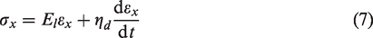
The filament bundle is a kind of fiber assembly with an ultrahigh length–diameter ratio. For textiles, the filament is an intermediate product in the textile production process. For ease of storage, transportation and subsequent processing, the filament is wound to form a disc-shaped package with a certain size. During winding, the high-speed moving filament is placed precisely on the cylindrical surface of the package with the spiral shape by the traverse mechanism. Unfortunately, uneven tension of the filament during reversing is caused by the action of the traverse mechanism, which directly affects the quality of the filament package. In this article, the approach of modeling and simulating the filament winding system was proposed, of which the element model of the filament was established by the absolute node coordinate formulation, considering its viscoelasticity, as well as the effect of gravity. The contact model between the filament and the rotary vane, as well as the contact roller, was established by the Hertz law. The equations of motion for the system were derived by the Lagrange equations, and the algorithm for solving the differential-algebraic equations was further derived. Then, the dynamic behavior of the winding system during reversing was simulated and analyzed, and the results show that the moving filament is in non-contact with the rotary vane at the moment of reversing, and the small fluctuation in contact force between the rotary vane and the filament causes the large fluctuation in the filament tension. Finally, the validity is tested through an experiment.
During spinning, the molten polymer, on emerging from the spinneret, bulges slightly, the filament is then quenched and solidified in the quench chamber while being drawn off from the bottom, and the filament diameter reduces and a number of these filaments are made. Finally, the filament is usually wound on a paper tube to form a disc-shaped package with a certain size by a winder, namely the filament package, which facilitates the storage, transportation and subsequent processing in actual production.1–3
The moving filament is placed precisely on the cylindrical surface of the package layer by layer via the rotary vane of the mechanism. Since the rotary vane acting on the filament needs to be replaced with another rotary vane during reversing, the dynamic characteristics of the moving filament have a great influence on its winding formation, and insufficient control of the filament tension will cause the edge collapse phenomenon of the package. Therefore, it is an important part of researching the dynamic behavior of the moving filament in the reversing process.
A moving filament with a large deformation in space is a common phenomenon during processing; some existing business software systems have certain limitations and cannot effectively study the dynamic characteristics of the complex system of the moving filament. To further research the dynamic characteristics of the moving filament via the method of modeling and numerical solution, the finite element model of the filament that can describe the large overall motions needs to be established, which is different from the beam element based on the small deformation. The excellent performance of the absolute nodal coordinate formulation (ANCF) is attributed to the fact that the slope vectors of the nodal coordinate employ finite rotations in the global coordinate system, and the method can avoid the parameterization problem of finite rotations. 4 Meanwhile, the equations of motion derived by the method have a constant mass matrix, and do not appear in Coriolis force and centrifugal force terms. In addition, the elastic deformation energy is calculated by the second Piola–Kirchhoff stress tensor and Green–Lagrange strain tensor, which are defined with respect to the reference configuration. Therefore, the ANCF can be used to establish the element model of the filament to investigate the dynamic characteristics of the moving filament accurately. 5 However, due to the huge degree of freedom of the element coordinate obtained through the ANCF, the dynamic equations are transformed into a numerical solving matrix with high dimensionality, resulting in low calculation efficiency. Besides, the shear deformation element established by the ANCF suffers from Poisson’s locking and shear locking 6 ; some scholars have proposed corresponding solutions for these problems.7–9
Currently, a few research works are reported in the published literature that study the dynamic characteristics of the moving filament via the ANCF. Campanelli et al. 10 investigated the dynamic behavior of the free falling of a flexible two-dimensional beam under the effect of gravity, but the model only considered the effect of gravity and elastic force. Yoo et al.11,12 analyzed the dynamic characteristics of a rotating light strip based on the ANCF, and verified the effectiveness through theoretical and experimental studies. Wang et al. 13 presented a new flexible multi-body system approach for modeling textile systems, including the filament and the draft rollers, using the ANCF, simulated a polyester filament bundle with oil and water and obtained its dynamic behavior. Wang et al. 14 and Li et al. 15 established the filament element model by using the ANCF, considering the action of air resistance and the dynamic viscoelasticity of the filament bundle, and studied its motion trajectories through experiment and simulation, respectively.
The trajectory of a moving filament in space is the result of the comprehensive effect of the external factors, as well as its inherent properties. At present, most of the research on the dynamic behavior of the moving filament mainly focuses on the trajectories,14–16 velocity and acceleration, as well as the tension control17,18 and so on, with less attention paid to the research of the winding process presently.
There are few studies on the dynamic behavior of the filament winding system during reversing. Up till now, many forms of the reciprocating yarn-guiding system have been used in the winding system, such as the grooved drum,19,20 shifting fork, 21 rotary vane, and so on. Singh and Singh 19 studied the finishing process to satisfy the requirement of finishing the grooved surface of the winding drum. Koranne et al. 21 modified the blade profile of the existing yarn traverse mechanism and developed three modified blade profiles. Lu et al. 22 proposed the linear magnetic reciprocating yarn-guiding system and investigated the motion characteristics of the reciprocating yarn-guiding mechanism. In addition, Li et al. 23 investigated the dynamic characteristics of the winding system during traverse conditions, considering the viscoelasticity of the filament. These works in the literature have attempted to analyze or explain the winding process and the impact of the traverse yarn-guiding system using different research types, but have not studied the dynamic behavior of the moving filament during reversing.
In this article, an analysis model of the traverse yarn-guiding system was proposed. Firstly, the element model of the filament was established by the ANCF, considering its dynamic viscoelasticity. Secondly, based on the Hertz contact law, the nonlinear spring damping impact–contact model was adopted to build up the contact force between the filament and the mechanical parts, and the contact force includes the normal contact force and the tangential friction force. The friction coefficient between the moving filament and the steel roller was measured by the experiment. Third, the dynamic equations of motion for the traverse yarn-guiding system were derived by the Lagrange equations, and were solved by the Runge–Kutta method. Then, the dynamic characteristics of the winding system for the filament were investigated to analyze the influence of the tension fluctuation during reversing. Finally, an experiment was carried out to verify the effectiveness of the simulation results in this paper.
Description of traverse reversing
Winding process of the polyester filament
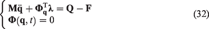
During winding, the moving filament is wound on the paper tube for ease of doffing from the spindle, and the paper tubes are fixedly connected with the spindle through the tightening device to realize synchronous rotation. 24 Subsequently, the moving filament is wound on the inner layer filament of the package with a specific helix through the traverse yarn-guiding system until the package is full volume, and one cycle of the filament winding is completed, as shown in Figure 1(a). In addition, to make the high-speed moving filament be placed precisely on the cylindrical surface of the package, the winder is equipped with a contact roller to press on the surface with an unchanged contact pressure, as shown in Figure 1(b).
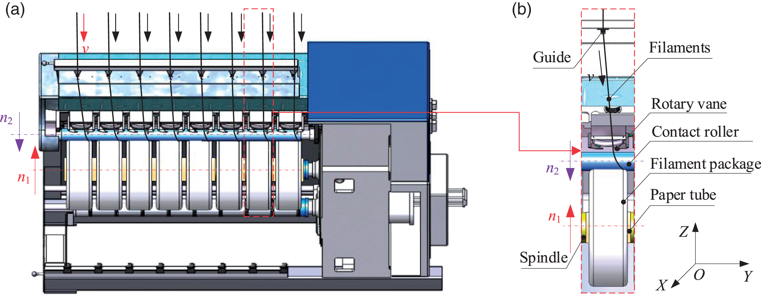
Schematic layout of a winder for the filaments: (a) schematic layout of the main structure of the winder for the filaments and (b) diagram of the local structure of the winder with a package.
Process of the traverse yarn-guiding system
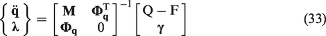
There are two rotating parts (rotary vanes A and B) in the traverse mechanism, and every rotating part has three rotary vanes. The two rotating parts have an eccentric distance
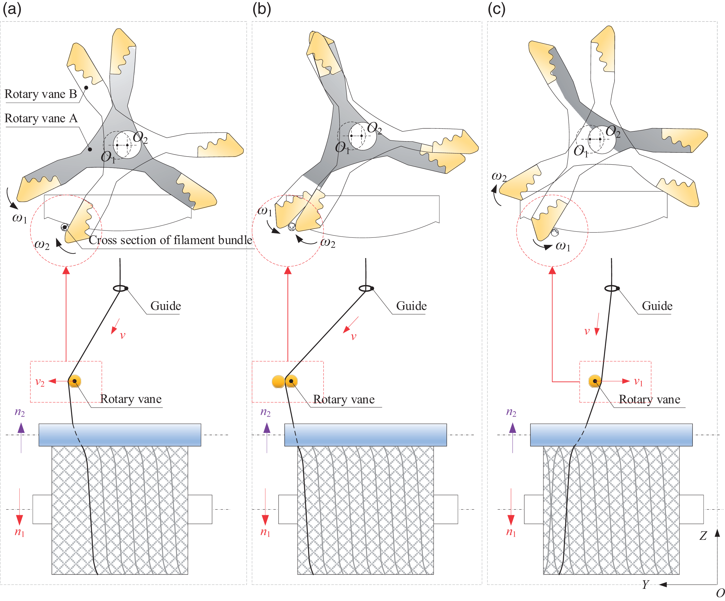
Schematic of the reversing process of the moving filament: (a) the moving filament moves to the left in the radial direction; (b) the moving filament begins to change direction and (c) the moving filament moves to the right in the radial direction.
To illustrate the distribution of helices of the filament more clearly, the view of Figure 1(b) rotates by 180° around the Z-axis. For a filament moving in the traverse process, there are three states of the moving filament in the winding process.
Mathematical modeling
Usually, the filament is composed of several or hundreds of monofilaments, which are almost parallel to each other, containing oil and water. If the moving filament has no special process, such as spreading, the filament bundle still retains the cluster state instead of dispersing in the spatial movement process.
For the moving filament in the winding system, air resistance acting on the filament surface is negligible due to the small traverse speed of the moving filament. In this article, the effects of filament tension, elastic force, gravity, contact–impact force and friction on the dynamic behavior of the moving filament were considered.
Filament element model
Motion description
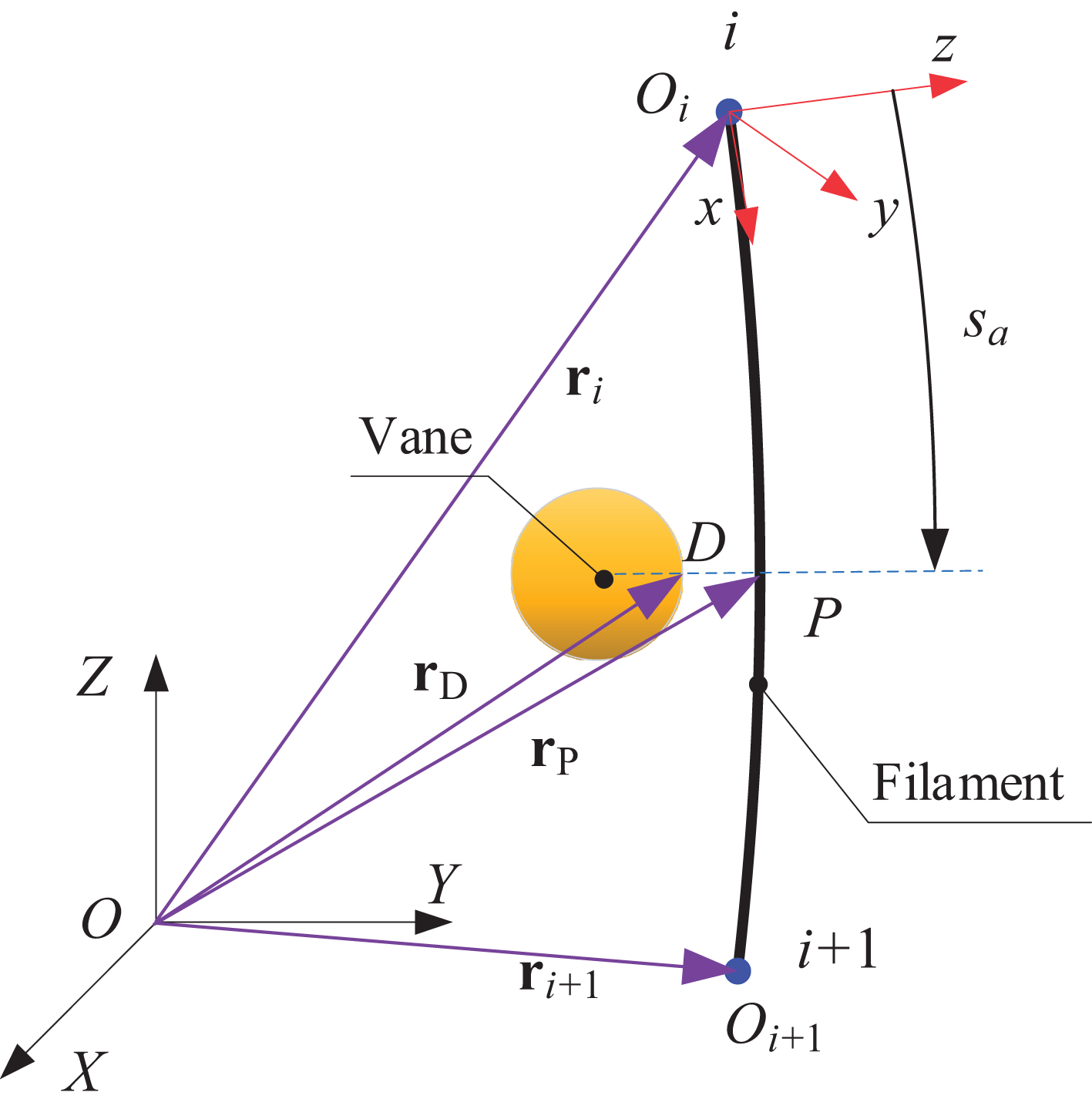
Consider the filament segment, which is subjected to either rotation or translation in the global coordinate system
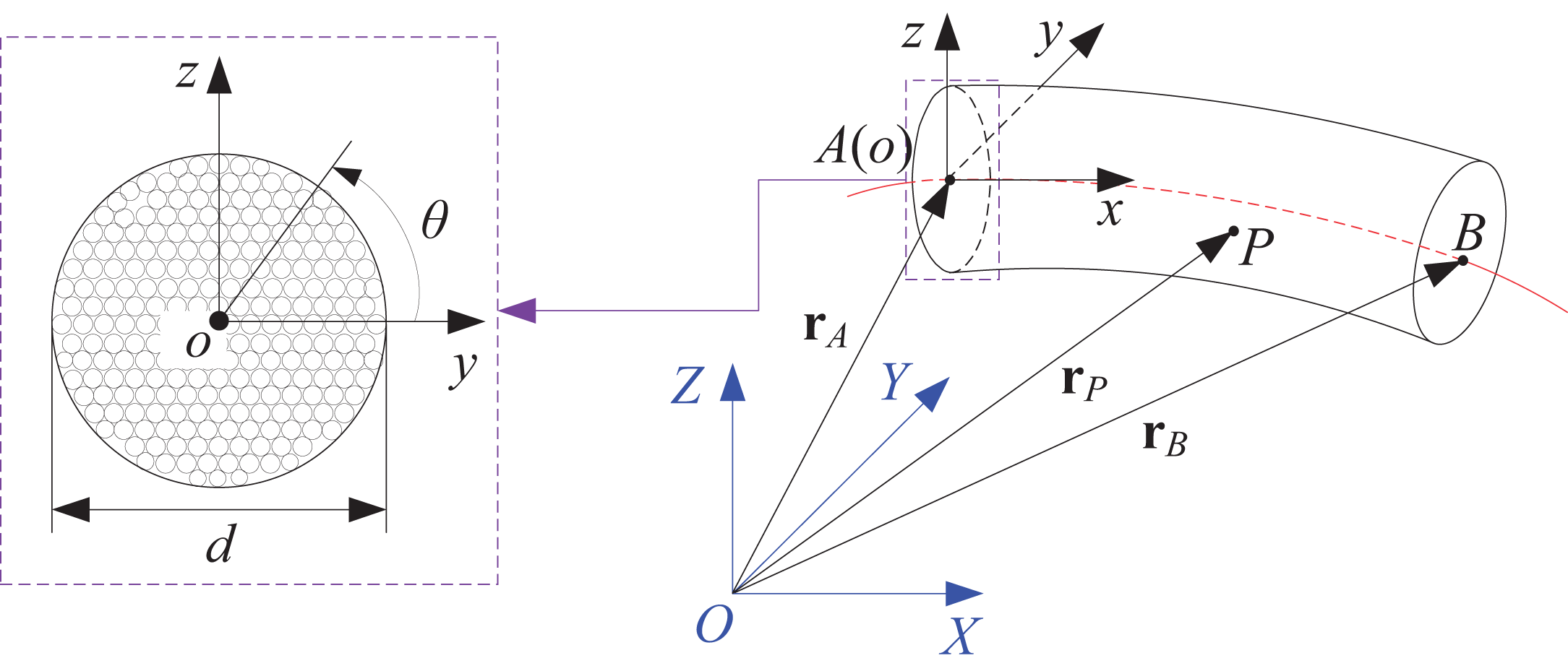
Element model of the filament.
The two locations of endpoints
Due to the filament moving in space, each node of the filament element needs six coordinates to be able to establish accurately the space position, including translational coordinate vector

For reasons of simplicity and analysis, it is assumed that the cross-section of the filament bundle is a circle in this article, and the equivalent diameter is
The global position vector of an arbitrary point P on the filament element at moment

The first position


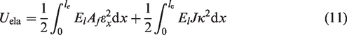
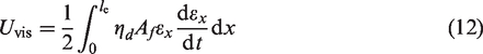
Work and energy
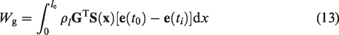
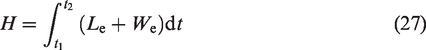
According to the principle of work and energy, by using Equation (2), the kinetic energy of the filament element in the inertial frame can be represented as


Here,
Contact–impact model
Collision detection
Since the nodes on the filament element move with the filament, the common collision detection method between the filament and other components is no longer applicable. In the absolute coordinate system O-XYZ, this article proposes to judge whether contact is made by the displacement vector between other components and the filament element, as shown in Figure 4.
Schematic diagram of the detection method between the rotary vane and the moving filament.
Suppose there are m detected parts, and the displacement vector is


When the position of the contact point of the detected object is in the filament unit, that is, between node i and node i + 1, as shown in Figure 4, the displacement vector of the point P on the filament can be calculated by Equation (2), and it can be written as

Thus, the relative distance between the other parts and the filament can be expressed as

Normal contact force model
To investigate the dynamic characteristics of the moving filament during reversing by means of numerical simulation, the contact force model between the filament and the mechanical component was established in this paper.
In this article, the contact force model was devised by the Hertz contact law, and the force

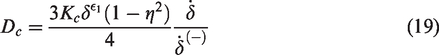
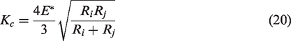
Here,
The contact–impact force vector in the global coordinate system can be written as
Tangential friction force model
When the filament is in contact with the rotary vane, due to the relative movement between the two objects, the dynamic behavior of the moving filament is also affected by the friction, and the friction


The generalized contact force vector in the absolute coordinates can be expressed as

Measuring the friction coefficient
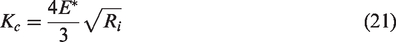
A Precision Frictionometer for moving yarn (model: LFY-110) was used to measure the dynamic friction coefficient of the moving filament; its test principle is the Rhodes method, as shown in Figure 5.
Measuring the dynamic friction coefficient of the filament bundle: (a) photograph of the Precision Frictionometer and (b) screenshot of the testing software.
In this article, the linear density 220 dtex of the polyester filament (POY 220 dtex/72 f) was used to measure the friction coefficient under its linear speed from 20 to 100 m/min. The diameter of the friction roller made of steel is 13 mm, and the test tension of the filament is 30 cN. During testing, the ambient temperature is 20°C and the relative humidity is 30%.
To ensure the stability of the moving filament during the test, first let the filament run for 30 seconds under the tension of 30 cN. Then begin measurement by pressing the start button, and the measurement results shall be recorded and each sample was measured six times, as shown in Figure 5(b). Finally, the dynamic friction coefficient of the moving filament was obtained under different linear speeds, as shown in Figure 6.
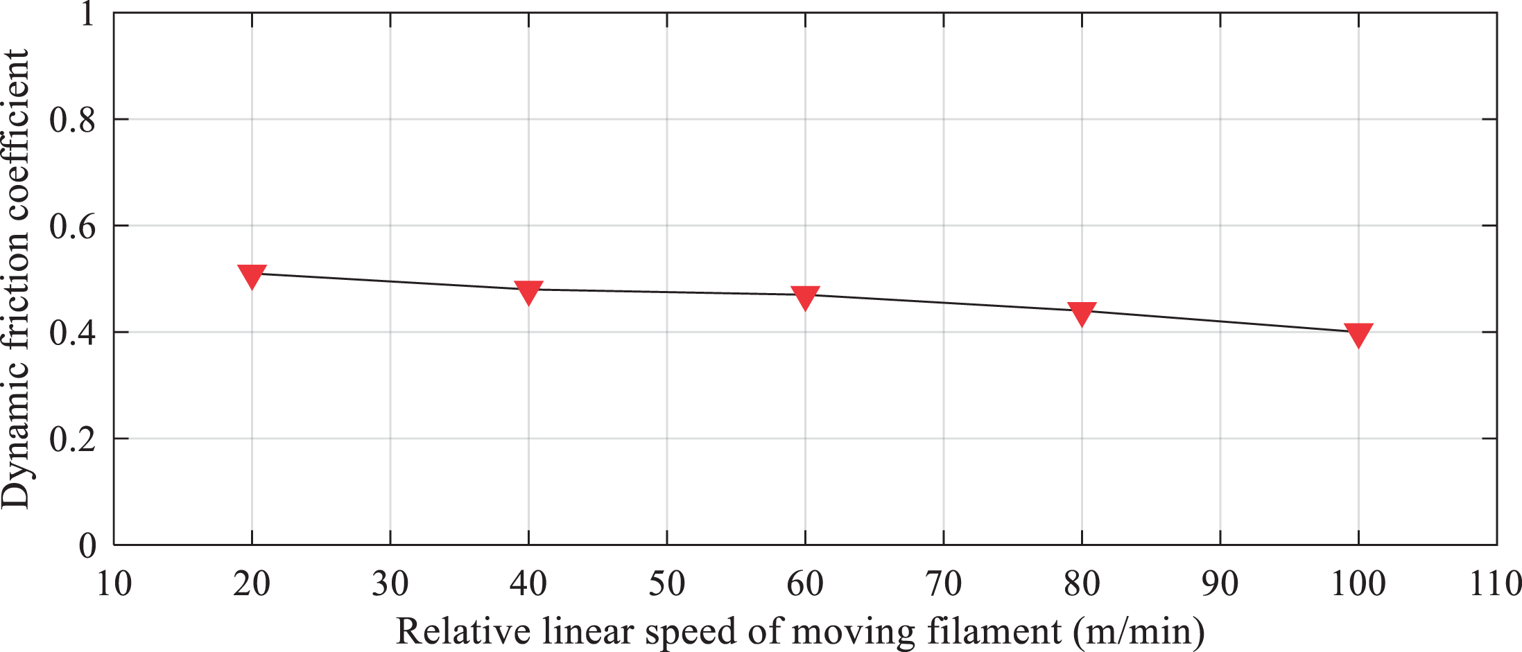
Dynamic friction coefficient of the moving filament under the different linear speeds.
As can be seen from the results shown in Figure 6, when the filament tension during the test is an invariant constant, the friction coefficient between the filament and the roller decreases with the increase of the relative linear velocity, and the curve presents an approximate linear relationship in a certain range of speeds.
Equations of motion and numerical solution
Equations of motion
Here,
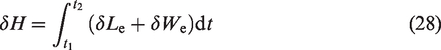
Then the first variation of the Hamiltonian can be expressed as


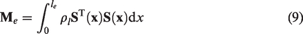
In the absolute nodal coordinate framework, the mass matrix
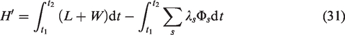
Assembly of the element matrix can be carried out by the conventional finite element method. According to Hamilton’s principle, we impose the condition
Numerical integration and stabilization
The DAEs transform into ordinary-differential equations, and the ordinary-differential equations can be expressed as
There are many studies about the solving methods of ordinary-differential equations, and the study of the ordinary-differential equation solving algorithm is in-depth, hence, many excellent algorithms can be used to solve ordinary-differential equations. However, due to calculation errors and other factors during the numerical solution, the position and speed constraints of the system will be violated, leading to the divergence or instability of numerical calculations. Therefore, the numerical solutions violating constraint equations were corrected by Baumgarte’s modification approach during the integration procedure, which is to form a closed-loop system of the constraint equations
25

The dynamic equations of the system with the control term can be written as


Case study
Numerical simulation
The moving filament is placed precisely on the package surface with the spiral shape by the traverse mechanism, as shown in Figure 7(a). During the traverse motion of the moving filament, since there is no impact force acting on the filament, the filament can be placed on the package surface according to the designed helix. When the filament bundle is wound to the end of the package surface, to make the filament be placed on the package surface, the direction of traverse motion of the filament must be changed by the traverse mechanism to complete the continuous winding. However, the fluctuation of the filament tension will be caused during reversing, namely, positions M and N. In order to illustrate the effect of changing directions on the filament tension, the model of the winding system was established, as shown in Figure 7(b), where Node 1 is the displacement constraint point, and
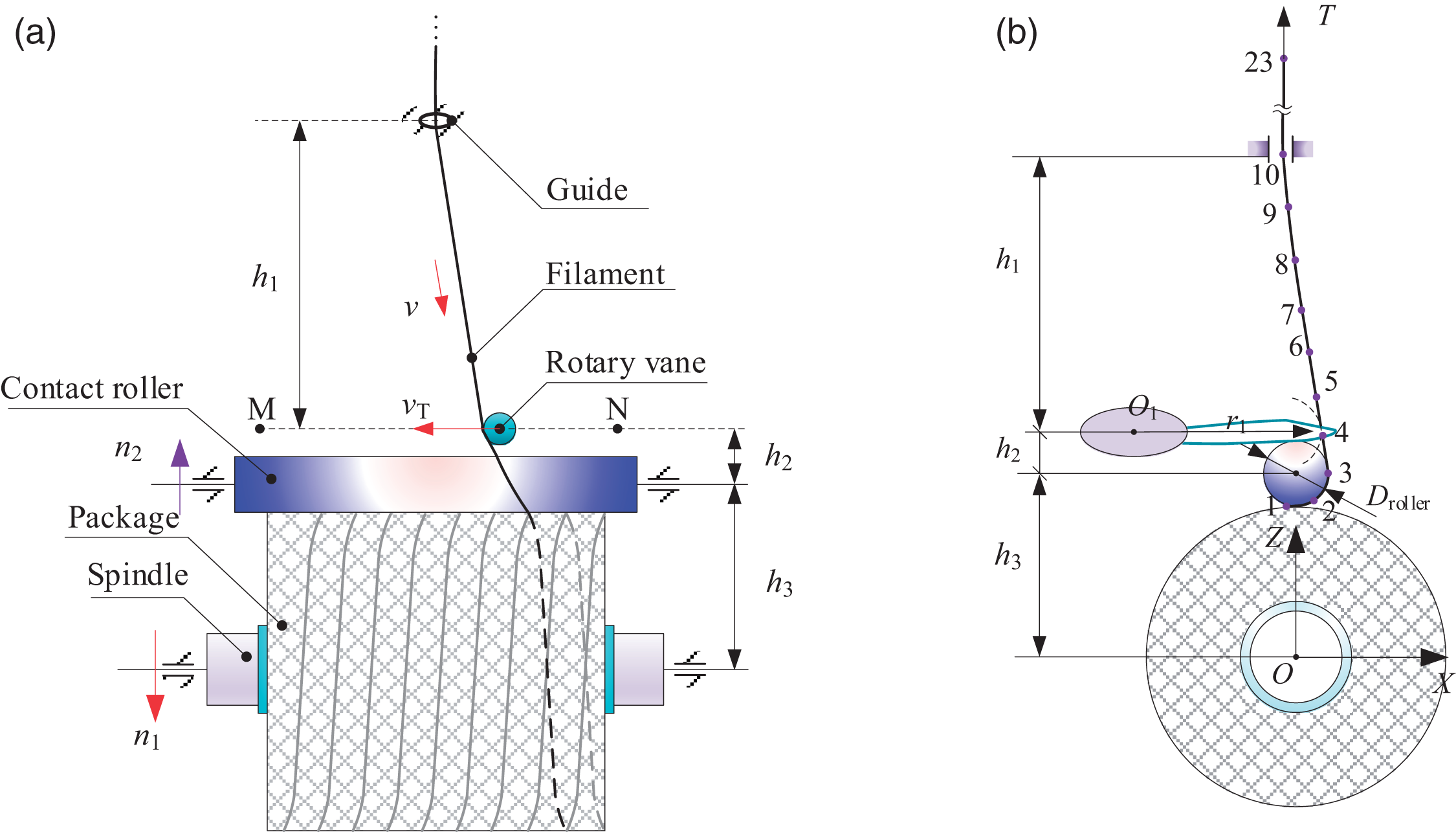
Diagram of the winding system: (a) structural schematic diagram and (b) initial configuration of the finite element model of the winding system.
In the process of the filament winding, the package width of 90 mm is selected for analyzing the dynamic characteristics during reversing in this article. It should be noted that when the package width is less than or equal to 90 mm, the motion trajectory of the traverse filament pushed by the rotary vanes is approximately a straight line, as shown in Figure 8(a). When the package width is greater than 90 mm, the trajectory is designed as a spatial curve, which can reduce the large fluctuation of the filament tension caused by the traverse motion of the filament, as shown in Figure 8(b).
Diagram of the motion trajectory acted on by two opposite-direction rotary vanes: (a) package width B ≤ 90 mm and (b) package width B > 90 mm.
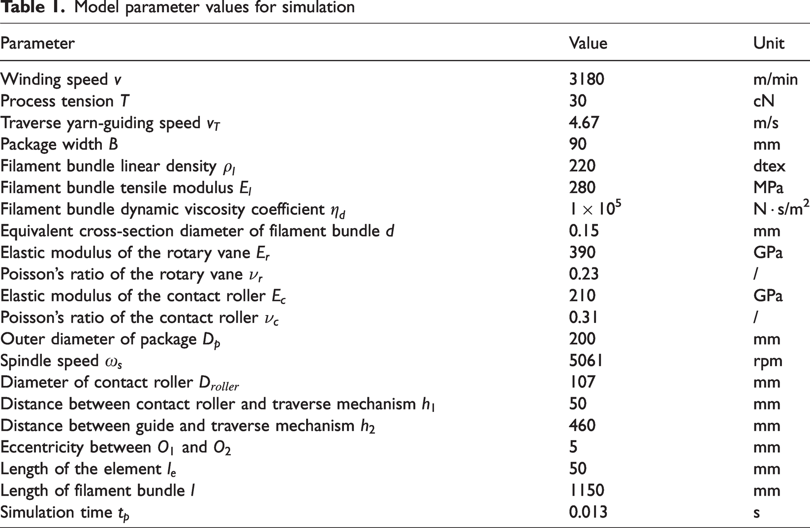
A polyester filament (POY 220 dtex/72 f) was used to study the dynamic characteristics during reversing. The linear speed of the filament is 3180 m/min in the process of practical production, and the filament tension is 30 cN. The structural and material parameters used in the simulation are listed in Table 1. To be clear, the two rotary vanes used for reversing reach the position M or N at the same moment, but the direction of rotation is converse.
Model parameter values for simulation
Based on the established analysis model, the corresponding equations of motion were solved by using numerical integration, and the flow chart is shown in Figure 9.
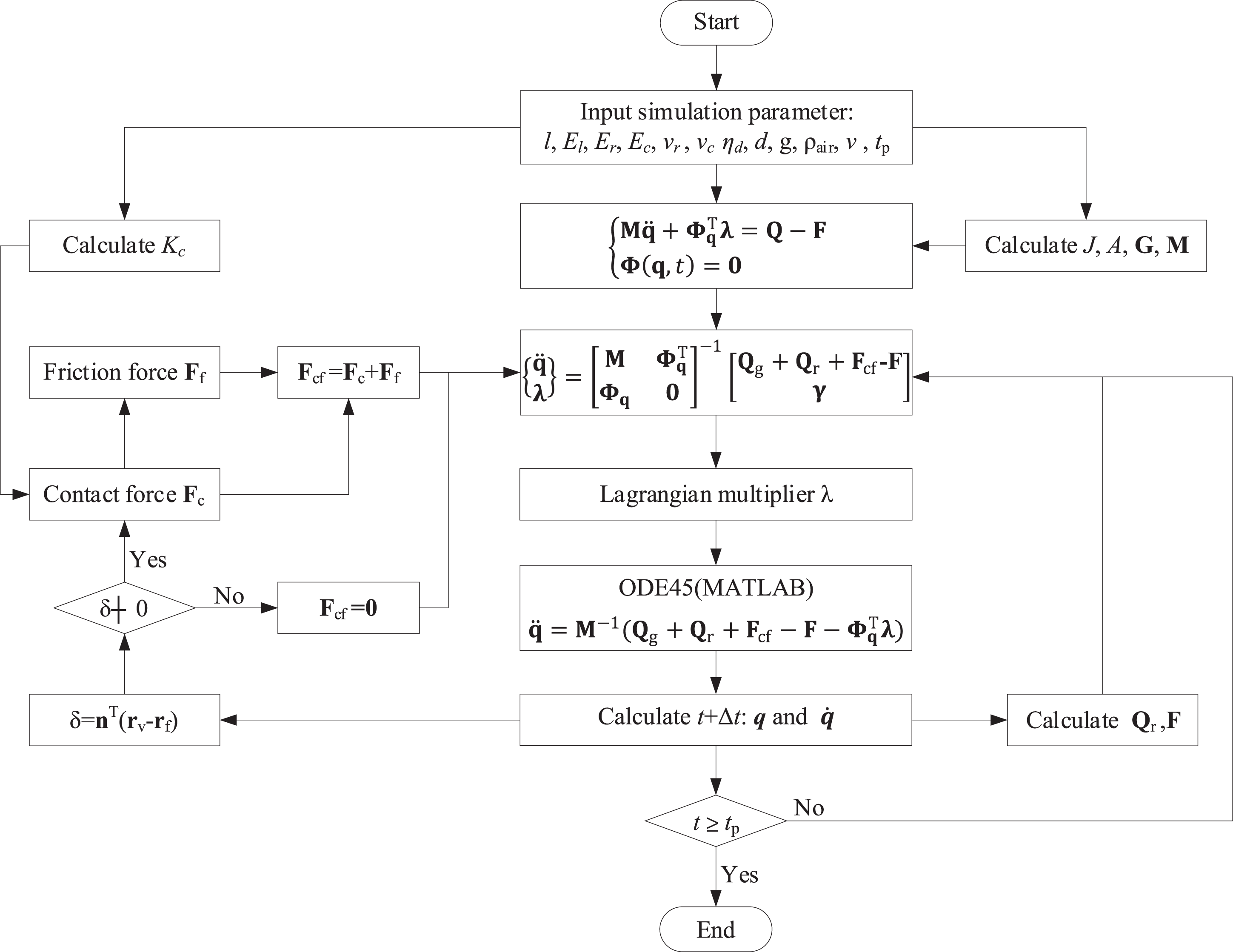
Flow chart for solving the equations of motion of the winding system.
The dynamic characteristics of the winding system during reversing were simulated through solving the equations of motion of the established model; the movement trajectory of the filament during winding can be obtained, and the movement trajectory of the filament at different times is shown in Figure 10.
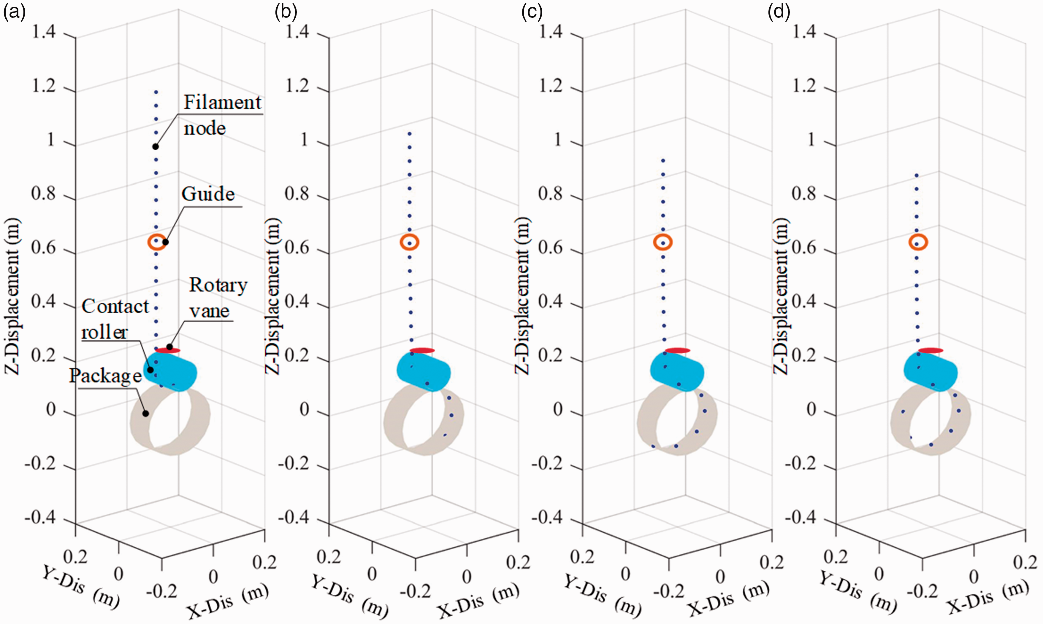
Diagram of the motion trajectory of the moving filament at different times: (a) t = 0.0045s, (b) t = 0.0078s, (c) t = 0.0101s and (d) t = 0.0119s.
In the simulation process of high-speed filament winding, according to the winding speed, the traverse speed and the simulation time, the radial movement distance and traverse movement distance of the filament are calculated, and the values are 754 and 60.7 mm, respectively. It can be seen from Figure 10 that the moving filament is wound on the package surface after passing through the contact roller surface, and the motion trajectory of the moving filament is consistent with the theoretical trajectory, which shows the effectiveness of the winding system model established in this article.
To observe the motion trajectory of the filament more clearly, the motion displacements of Nodes 1 and 3 in different directions are shown in Figure 11.
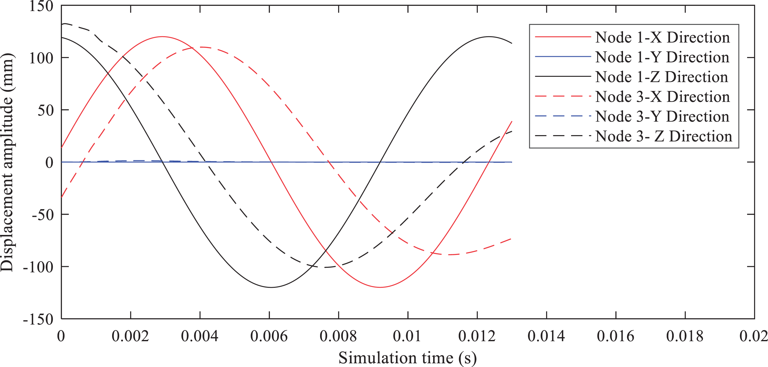
Displacement curves of Nodes 1 and 3 in different directions.
During winding for the high-speed moving filament, the displacement curves of Node 1 in the X and Z directions and the change pattern of the harmonic function are the same, as shown in Figure 11. However, the curves of Node 3 present a different variation, which is mainly caused by the draft of the filament during winding and the winding stability point being undefined in the modeling process. In addition, comparing the motion trajectory of the filament with the curves from Li et al., 23 the results demonstrate that the methods proposed in this thesis are correct and efficient.
Analysis and discussion
To study the change of the filament tension in the winding process further, Node 10 near the guide is selected as the investigated point, and the curve of the tension change during winding is shown in Figure 12(a).
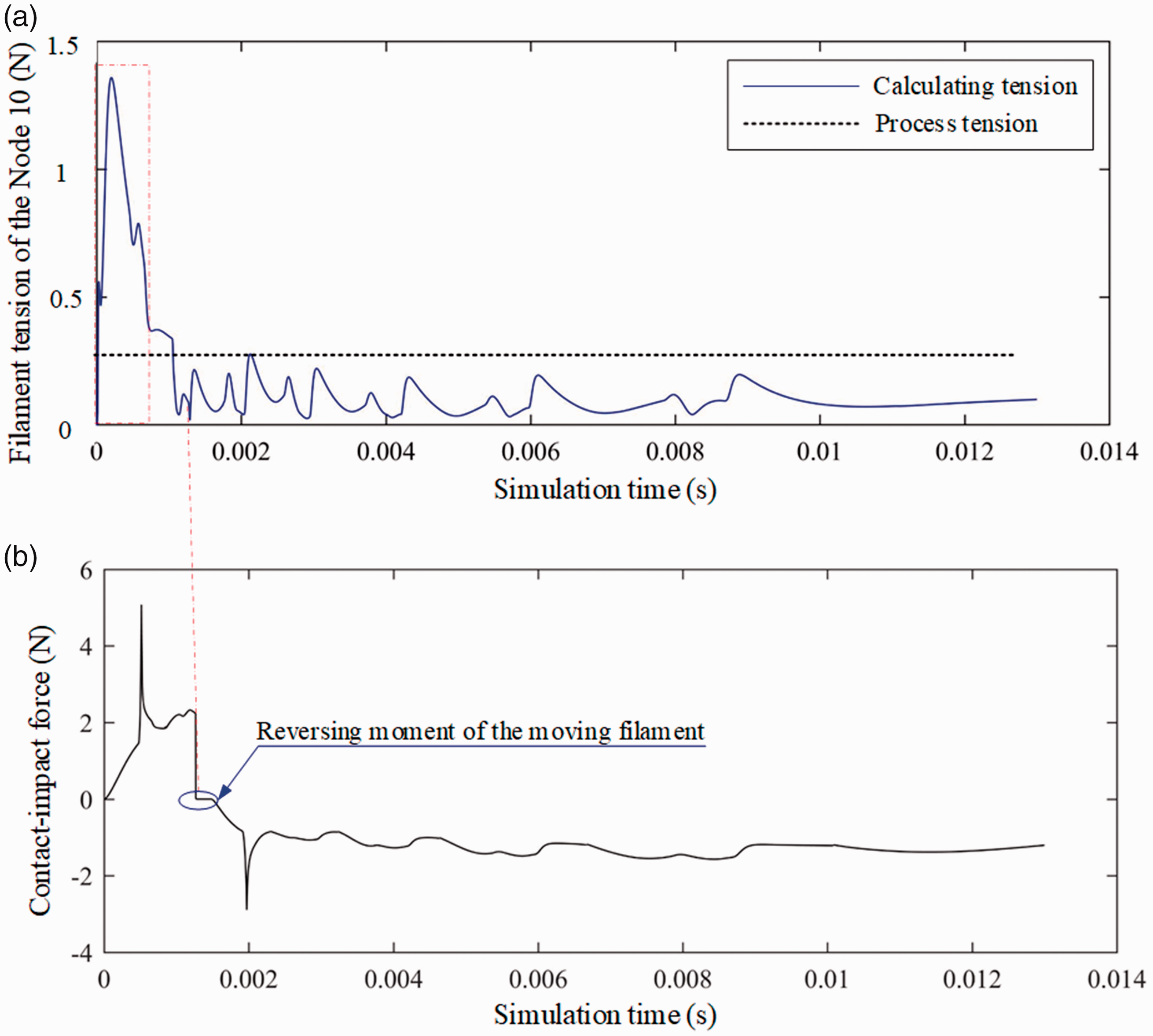
Filament tension and contact–impact force curves during winding: (a) relationship between the filament tension of Node 10 and simulation time and (b) contact–impact force between the rotary vane and the filament.
At the beginning of the simulation, because the moving filament just started to accelerate, the filament tension increased rapidly, reaching a maximum of 1.4 N, as shown in Figure 12(a). Then the filament tension fluctuated around 0.2 N (about 20 cN), a value that was lower than that of the process tension. Besides that, filament tension is the comprehensive result of the external force acting on the filament during the movement and the properties of the filament itself. In this article, the static equivalent process tension is loaded on Node 23, so the calculated tension (dynamic) of the moving filament is less than the static equivalent process tension.
During reversing, the contact–impact force curve of the rotary vane is shown in Figure 12(b), in which the contact–impact force of the rotary vane is zero for a short time (2.1 × 10⁻⁴ s) during reversing. The main reason for this situation is that there is a short-term non-contact state between the moving filament and the rotary vanes during the exchange of the two opposite-direction rotary vanes. After the reversing completed, the contact force gradually increased with the increase of the displacement of the traverse moving filament, and the maximum contact force between the moving filament and the rotary vane was about 1.5 N. Therefore, when designing the process parameters of the traverse mechanism, the rotary vane used for pushing the filament should reach the position M or N 2.1 × 10⁻⁴ s before another vane is exchanged to avoid the moving filament being in an unconstrained state in the traverse direction. Alternatively, a novel traverse device, such as the traverse system of the camshaft, can be adopted to improve the dynamic characteristics of the moving filament during reversing.
Comparing the curves between the traversing contact force and the filament tension, it can be seen that a little fluctuation of the contact force acting on the filament by the rotary vane will cause a relatively large fluctuation of the filament tension. Therefore, the accuracy of the exchange of the two opposite-direction rotary vanes needs to be reasonably designed in the process of the traverse filament to prevent the filament from being in non-contact with the rotary vane at the moment of traverse reversing. In addition, the stability of the rotary vanes needs to be controlled to reduce its vibration in the process of winding. If necessary, active vibration control is performed to reduce the fluctuation of the filament tension and improve the quality of the spinning.
Effectiveness analysis
In order to verify the effectiveness of the model that is established in this article, the experimental testing of the winder for the filament during winding was carried out. The winding process parameters of the test are the same as those in the simulation in the Numerical simulation section, and these parameters are listed in Table 1. Through a digital high-speed camera (model: GX-3), the motion trajectories of the various stages were captured and memorized by a computer (HXLink software), where the sampling frequency of the camera is 4000 Hz. A photograph of the experimental device and instrument is shown in Figure 13.
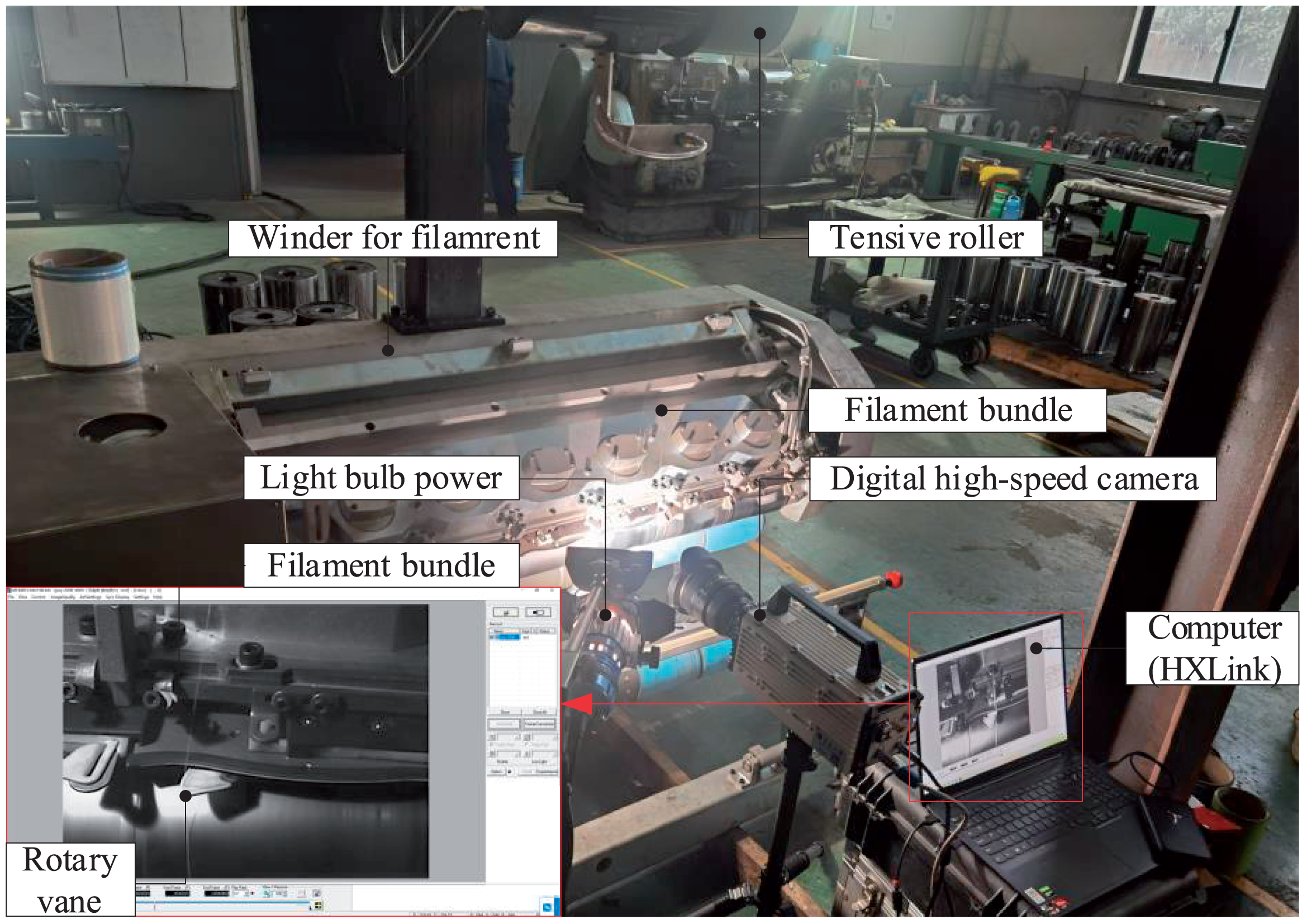
Experimental setup.
The motion trajectories of the filament bundle at different time points were obtained through the experiment during reversing, as shown in Figure 14. It can be seen from Figure 14(c) that there is a certain distance
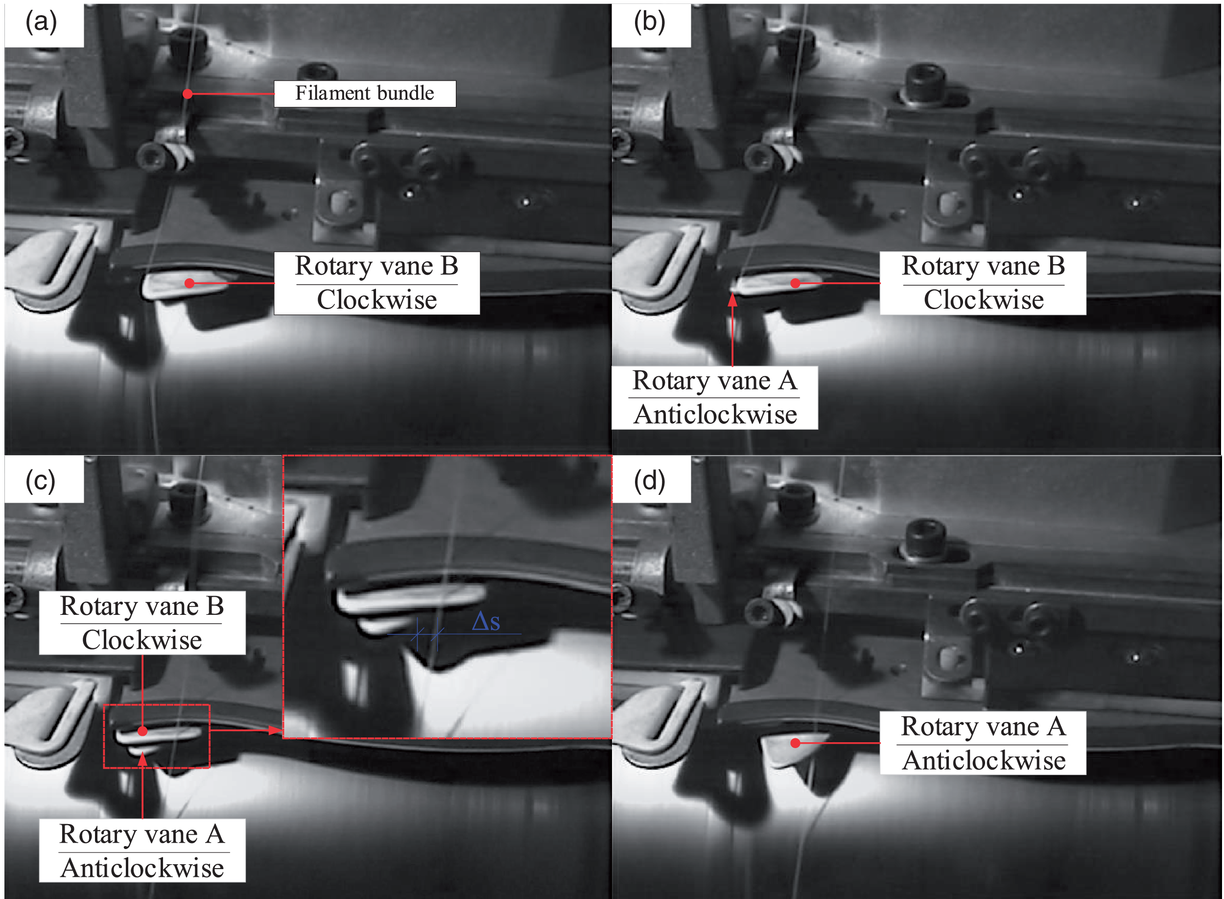
Motion state of the filament bundle at different times: (a) the moving filament moves to the left in the radial direction; (b) the moving filament begins to change direction (critical state of motion); (c) non-contact state between the rotary vane A and the filament bundle and (d) the moving filament moves to the right in the radial direction.
Conclusions
In this article, the dynamic behavior of the moving filament in the winding process was simulated and analyzed, and the results show the following:
The moving filament is in a short-term non-contact state with the rotary vane at the moment of traverse reversing, that is, the traverse movement of the filament segment between the guide and the winding point is in an unconstrained state along the radial direction of the filament bundle, and the correctness of the results is verified by experimental methods. During winding for the high-speed moving filament, the relatively small changes in contact force between the rotary vane and the filament bundle cause the significant fluctuations in filament tension.
The occurrence of these two situations will affect the quality of the filament and the high-speed and precise winding of the filament, which requires accurate analysis and then precise control of the dynamic characteristics of the polyester filament winding system.
Footnotes
Declaration of conflicting interests
The authors have no conflicts of interest to declare.
Funding
The authors disclosed receipt of the following financial support for the research, authorship and/or publication of this article: This work was supported by the National Natural Science Foundation of China (grant number 52103355).