
Abstract
We aimed to develop a low-power heating mat based on a carbon nanotube (CNT) planar heater and verify its performance by utilizing the heating element. The cell samples were manufactured, and their electrical and thermal properties were evaluated to conduct heating tests. The developed CNT planar heater was tested in four ways, namely heating one cell individually and heating two/three/four cells simultaneously. When operating multiple cells, the resistance decreased, and the power increased. The temperature averaged 37°C even when multiple cells were operating, and the power consumption per unit area was at a similar level. In addition, a prototype heating vest was fabricated using the cells, and a performance comparison was conducted with a third-party heating vest product. The heating efficiency was more than twice as high as that of the third-party product, and the heating area was more than twice as large. Prototype heating pads were made using the cells and compared with two other third-party samples that are heated by thermal wires, and the developed prototype was found to have a heating efficiency more than 20% higher than the other samples, with the lowest temperature deviation. The CNT planar heater developed in this study can be realized in various shapes without wires and can be used safely. It is economical because it can be set to the appropriate temperature in the desired area with a controller, and it is eco-friendly because it prevents mold growth by emitting far-infrared radiation.
The current heating mat market is expanding; the global market for heating mats was approximately $49.02 billion in 2022, and the compound annual growth rate from 2023 to 2030 is estimated to be approximately 5.19%. The market is expected to grow to approximately $73.61 billion by 2030. 1 This growth is because of the increasing elderly population worldwide, the trend of single-person households, and the preference for convenient heating devices. 2 The rising prevalence of knee pain, muscle aches, and blood circulation issues among the elderly, along with menstrual pain issues in female consumers, is expected to contribute to the steady growth of the market, as these issues can be alleviated through heating mats and pads.3,4
Several products have been released in this regard, but these existing products still have various drawbacks. These drawbacks include incidents of fire and safety issues owing to manufacturing defects.5,6 In addition, there are concerns regarding low-temperature burns on the skin, 7 electromagnetic radiation, and energy inefficiencies. 8 This situation can be interpreted as an opportunity for market expansion; however, products that satisfy consumer expectations have not been developed.
Heating mats need to have an efficient heating performance, and as they come into direct contact with the human body, they should also be free from emitting electromagnetic waves and be safe from risks such as fire, burns, electric shock incidents, and radon. It is crucial for them to exhibit high energy efficiency and low electric power consumption. If they can provide fast heating, emit infrared radiation, and feature low thickness, they will be differentiated in the existing heating mat market.
Flexibility and the ability to heat specific areas are crucial for heating mats. If a heating mat is flexible, its softness can enhance its usability and storage. In the case of a planar heater with a coating method that does not use heating wires, the mat thickness can be reduced because the thickness of the heating wires is not negligible. When using heating wires, there is a risk of wire breakage, generation of carbon dust owing to bending, and accidents owing to cracks. However, several existing products and studies utilize carbon heating wires, and further development of mats to complement or replace heating wires is required.9 –11
Incorporating a function into the heating mat that allows users to heat only selected areas can reduce power consumption and lower the probability of fire and burn accidents. Although existing products and studies have added devices that independently control the heating wires in heating mats, accidents have occurred when the wires are disconnected.2,5 Therefore, there is a need to selectively heat specific areas in mats manufactured using methods other than the use of heating wires.
Studies have been conducted to address the issues of existing heating mats, such as electromagnetic wave generation, high power consumption, and reduced heating speed.9,12 Efforts have been made to enhance heat and flame resistance to minimize the risk of fire 10 and to develop a portable heating mat. 13 However, there is a lack of studies on developing flexible heating mats that can independently and simultaneously heat selected areas within the mat, considering energy efficiency and heating speed.
Thus, this study focused on heating mats utilizing carbon nanotube (CNT) planar heaters. There are potential advantages to applying CNTs to planar heaters through special coatings to achieve higher energy efficiency and faster heating speed. We developed a heating mat using a CNT planar heater to mitigate the drawbacks of existing products. This mat exhibited high heat uniformity and flexibility owing to the absence of internal wires in the heating element, providing durability even when bent. It also has the advantages of the independent heating of user-selected areas and simultaneous heating. By heating only the area that the user wants, the power consumption can be low, avoiding using unnecessary power, which can reduce heating costs. When the product is manufactured by applying the developed cell, it is safe from electromagnetic waves, using direct current (DC) power, and the thickness is very low (less than 1 mm); therefore, the product can be used without inconvenience.
Therefore, this study primarily focused on planar heater technology, which is the most significant feature of the developed heating mat. We focused on the independent and simultaneous heating functionality of selected areas within the mat when applying the planar heater. We conducted experiments to measure and compare variables representing the electrical and thermal characteristics. The power efficiency of the developed heating mat was also evaluated. It is expected that the results will help CNT planar heater technology become more widely used in the fields of heating mats and sheets.
Literature review
Carbon nanotube planar heater technology
CNTs are advanced nanomaterials with excellent electrical and thermal conductivities, high strength and elastic moduli, low friction coefficients, and flexibility, making them applicable in various fields. 14 The principle behind their application involves applying electrical energy to carbon; because of the resistance of carbon, electrical energy is converted into thermal energy, leading to heating. 15 This principle is utilized in various applications, such as heating mats, outdoor clothing, and vehicle heating seats.10,11 CNT inks can be liquefied and surface-coated using various coating methods, such as spin coating, dip coating, and spray coating.16 –18
CNTs are irradiated and fabricated into a web structure, which is then compressed using two rollers to produce a film. 19 The application of a CNT coating to a planar heater involves a special coating on the heater surface to induce heating. This innovative technology utilizes a surface-based heater rather than a conventional wire-based approach, thereby increasing the energy efficiency and maximizing the heating area per unit surface. 20 When an electric current is applied to a resistive CNT flat coating layer, heat energy is generated because the collision of the atoms that make up the material in the coating layer with the electrons traveling through the material causes an energy conversion that changes electrical energy into heat energy. This enables low-power operation compared with wire-based heaters while providing excellent heat diffusion and emission characteristics, resulting in highly efficient energy consumption. The efficiency of uniformly heating the entire surface and the ease of rapid temperature control contribute to the competitiveness of this technology in the market.21,22
A heating mat comes into direct contact with the human body and not only requires safety from electromagnetic waves, 9 radon, 23 and electrical fires, 5 but also superior thermal efficiency, uniform heating, selective area-heating capabilities, and low power consumption. Therefore, it is anticipated that the development of products with well-rounded performances in these aspects will contribute to the growth of the electric heating mat market.
Trends in prior research on heating mats
With the growth of the heating mat market, 2 the demand for carbon-based heating mats has increased. Accordingly, several previous studies have investigated carbon-based heating mats. For example, a portable blind-type heating mat woven with carbon fibers in the form of heating wires has been developed. 12 Heo et al. 9 devised a parallel carbon fiber heating circuit, resulting in a 50% reduction in power consumption compared with traditional wire-based heating mats, along with a 1000% increase in heating rate. In addition, by applying nanocarbon material dispersion technology, a functional carbon-heating yarn was developed to enhance the flexibility of carbon heating mats by directly quilting them into various patterns. 11
According to research trends, most heating mats utilize carbon in the form of heating wires. Previous studies on planar heaters using carbon nanofibers were limited to applications in ship materials and marine structures.20,24 However, there are insufficient studies on the application of CNT planar heaters in heating mats. The introduction of CNT surface coating technology to heating mats is expected to provide advantages, such as superior thermal efficiency, uniformity, high power efficiency, and heating of the entire mat, unlike conventional wire-based applications.9,11,12 In addition, planar heaters, as opposed to wires, offer improved durability and safety, mitigating the vulnerabilities and avoiding the potential release of carbon particles owing to bending. 25
Therefore, in this study, we aimed to develop a heating mat using CNT coating technology. Accordingly, we planned to utilize a CNT ink manufacturing method that employs an aqueous solvent to coat without causing damage to the existing fibers and to minimize wastewater during production. We designed experiments and fabricated samples for evaluation to assess the power and temperature performance of the heating mat produced using this method.
Main variables and performance measurement
In this experiment, we used a heating test apparatus to compare the temperatures before and after heating. We measured and compared voltage (V), current (A), resistance (Ω), and power (W) under different conditions.26,27
This study aimed to develop a low-power plane heater for heating mats that can independently and simultaneously heat selected areas, enabling energy conservation through reduced power consumption. The developed heating mat utilized a DC circuit, eliminating the reactive power and power factor in the power consumption, requiring only the active power. The measurement of relevant variables, including voltage (V) and current (A), is required for the calculation (P = VI) of the active power (P), expressed in watts.28,29 Thus, we examined voltage (V), current (A), resistance (Ω), and power (W) in this study.
The developed heating mat utilizes CNT coating technology and offers the advantages of individual and simultaneous heating in a user-selected cell area. Therefore, experiments were conducted to confirm the power efficiency of simultaneous heating by gradually increasing the number of cells from one to four to measure the corresponding electrical and thermal characteristics.
Previous studies evaluating the performance of heating mats have also involved measurements of temperature, voltage, current, resistance, and power.30,31 Grm et al. 30 developed a heating car seat using a conductive film based on a CNT material, created by screen printing on fabric. Subsequently, current, voltage, and temperature were measured. For a heating sheet sample measuring 20 cm in width and 20 cm in height, subjected to a voltage of 24 V, the authors measured the current, confirming a linear relationship between current and voltage with a current of 40–100 mA flowing at a reference voltage of 15 V, following Ohm’s law. In addition, applying a suitable voltage and current (12–24 V, 50–150 mA) to a 15 g sample measuring 10 cm in width and 20 cm in height, they observed a temperature rise of 45°C within 2 min. Similar to the present study, the authors employed a method of manufacturing and coating a substance based on CNTs, demonstrating that it allowed more uniform heating than a carbon-wire-based heater and reduced power consumption.
Han et al. 31 developed a heating sheet using carbon black based on the positive temperature coefficient principle, and conducted measurements and comparisons of power, current, and temperature. Five heating sheets were cut to the dimensions of 1 m in width and 1 m in height for measurement. The results indicated that the power consumption was reduced to 1.4 kWh compared with that of the conventional wet ondol system (1.5–1.7 kWh). The current reached a steady state approximately 18 min after the power was supplied. Comparing temperature changes one hour later, the temperature varied depending on the power usage, ranging from a minimum of 60°C to over 120°C.
Accordingly, we comprehensively evaluated the heating performance by measuring electrical characteristics, such as voltage, current, resistance, power, and thermal characteristics including the temperature before and after heating. Ultimately, the efficiency of the power consumption was determined by comparing the temperature and power consumption of a single cell with those of multiple cells operating simultaneously.
Method
To evaluate the heating mat’s performance, samples of the cell were manufactured. The developed cell was divided into four parts and tested for electrical and thermal properties. The heating element operates as a resistor for heating in each zone and is divided into four zones that can be powered on/off independently. All the electrical circuits comprise conductive yarns inside the fabric, which are made of two strands of 50 µm-thick silver-plated copper yarn and polyester thread (15 denier), and 35 strands of conductive yarns make up the electrical circuit (see Figure 2(e)). In this experiment, the resistance values of the copper thread and the copper tape were compared to determine the dispersion of the resistance values. The resistance value of the copper thread was 7.419 Ω at 1 m, whereas the resistance value of the copper tape was 0.188 Ω at 1 m. As the number of strands of the copper thread increases, the resistivity tends to decrease, proving that there is a dispersion of resistivity values. This indicates that the resistivity value depends on the shape and composition of the material, which is experimental verification of the dispersion of the resistivity value.
The experiment was divided into two main parts. The first was to verify the performance of the developed cell, and the second was to compare the difference between the prototype sample of the developed cell and two samples of the thermal heating wire method sold on the market. For each experiment, an ammeter was used to evaluate the electrical characteristics, a thermal imaging camera (FLIRONE PRO) was used to identify the thermal characteristics, and FLIR (Forward Looking Infrared) Tools was used to measure the temperature. FLIR Tools was mainly used to detect thermal changes in the surrounding environment and to measure the images captured by a thermal imaging camera because the thermal and visible images can be viewed simultaneously on a computer monitor. We also used electromagnetic compatibility test equipment (Keysight N9030A PXA Signal Analyzer) to test for electromagnetic interference and ensure compliance with electromagnetic compatibility standards; voltage and current meters (TS3010A 0-30V, 0-10A and TDP-1005B 0-100V/0-5A) to measure voltage and current; and a multichannel temperature detector (ET3916-16 Multichannel Temperature Detector) to measure temperature up to 16 channels. The first experiment involved four experimental methods to verify the performance of the developed cells: heating one cell individually and heating two/three/four cells simultaneously. The second experiment was to compare the thermal characteristics between the prototype sample of the developed cell and two samples of the thermal heating wire method sold on the market. This experiment was conducted to verify the performance of the prototype sample of the developed plane heater prototype sample surface in terms of heating efficiency when compared with the third-party sample of the heating wire type. Voltage (V), current (A), resistance (Ω), and power (W) were compared according to the conditions of the methods, and the temperatures before and after heating (°C) were compared to evaluate the heating performance.12,26
Voltage (V), current (A), resistance (Ω), and power (W) measurements can be used to evaluate the power consumption, energy efficiency, safety, production, and quality. 32 The experimental procedure for the developed cell is illustrated (Figure 1). In this study, tests were conducted in accordance with IEC 60335, 32 a test standard that certifies the electrical safety for household, commercial, and similar applications to ensure consumer safety. 33 First, a 1 cm-thick quilt was prepared to form an insulating condition, and each sample was placed on the quilt. Next, a 1 cm-thick quilt was placed over the cell to be tested. 32 Finally, the current was applied for 20 min and each test was photographed using a video camera.32,34 For each test, the third (③) and fourth (④) segments were identically assessed. 32 In the experiments on the developed cell, the first test was a one-cell individual heating test, and a total of four experiments were conducted with one test for each part of the cell (Figure 2(a)). In the second experiment, simultaneous heating tests on two cells were performed; cells 1, 2, cells 3, 4, and cells 1, 4 were tested once, and three experiments were performed (Figure 2(b)). In the third experiment, simultaneous heating tests on three cells were performed; cells 1, 2, 3 and cells 1, 2, 4 were tested once, and the two-cell test was performed twice (Figure 2(c)). Finally, in the fourth experiment, a single four-cell simultaneous heating test was conducted (Figure 2(d)). The experiment to compare the developed sample with a third-party heating sample was conducted for 10 min, and the results were compared in terms of the heating area, resistance (Ω), temperature after heating, the highest temperature during the test, the average temperature for the heating area, and temperature deviation.35 –37
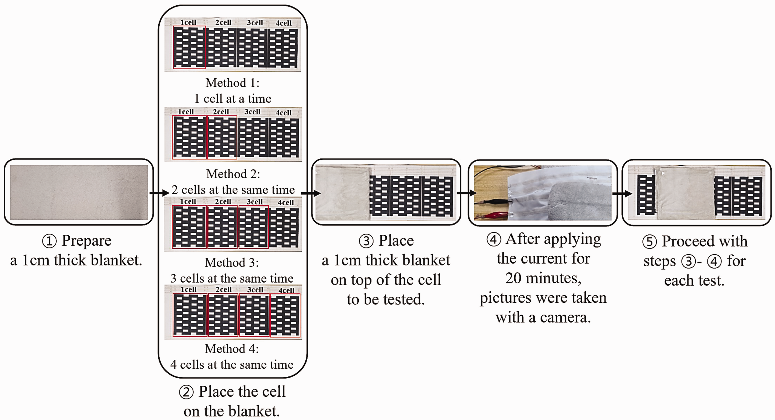
Heating test protocol.
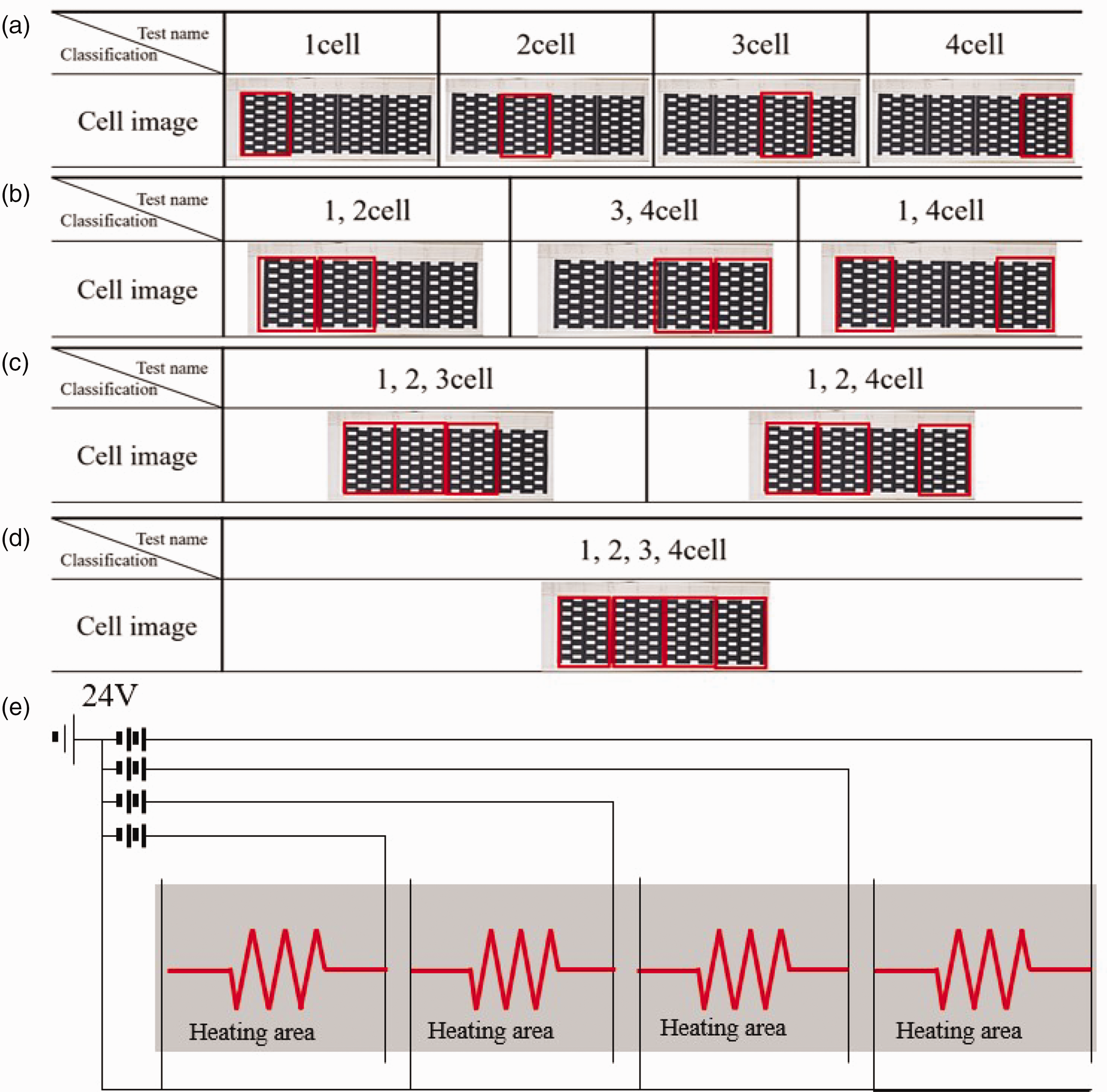
Test methods: (a) Method 1: heating one cell individually, (b) Method 2: heating two cells simultaneously, (c) Method 3: heating three cells simultaneously, and (d) Method 4: heating four cells simultaneously; (e) Circuit diagram of a heating mat.
Results
Experimental results for the developed cells
Electrical characteristic test results
Figure 3 shows the results of electrical characterization experiments for four methods (one cell heated individually, two cells heated simultaneously, three cells heated simultaneously, and four cells heated simultaneously). The results of Method 1 show that the voltage measurement is the same 15 V for one cell to four cells; the results of Method 2 show that the voltage measurement is the same 15 V for (1 and 2 cells), (3 and 4 cells), and (1 and 4 cells); the results of Method 3 show that the voltage measurement is the same 15 V for (1, 2 and 3 cells) and (1, 2 and 4 cells); and the results of Method 4 show that the voltage measurement is the same 15 V for (1, 2 and 3 cells) and (1, 2 and 4 cells). In Method 4, the electrical characteristic experiment showed that (1, 2, 3 and 4 cells) showed 15 V in the voltage measurement. In addition, we can see that the current, resistance, and power characteristics are uniform in Methods 1, 2, 3, and 4.
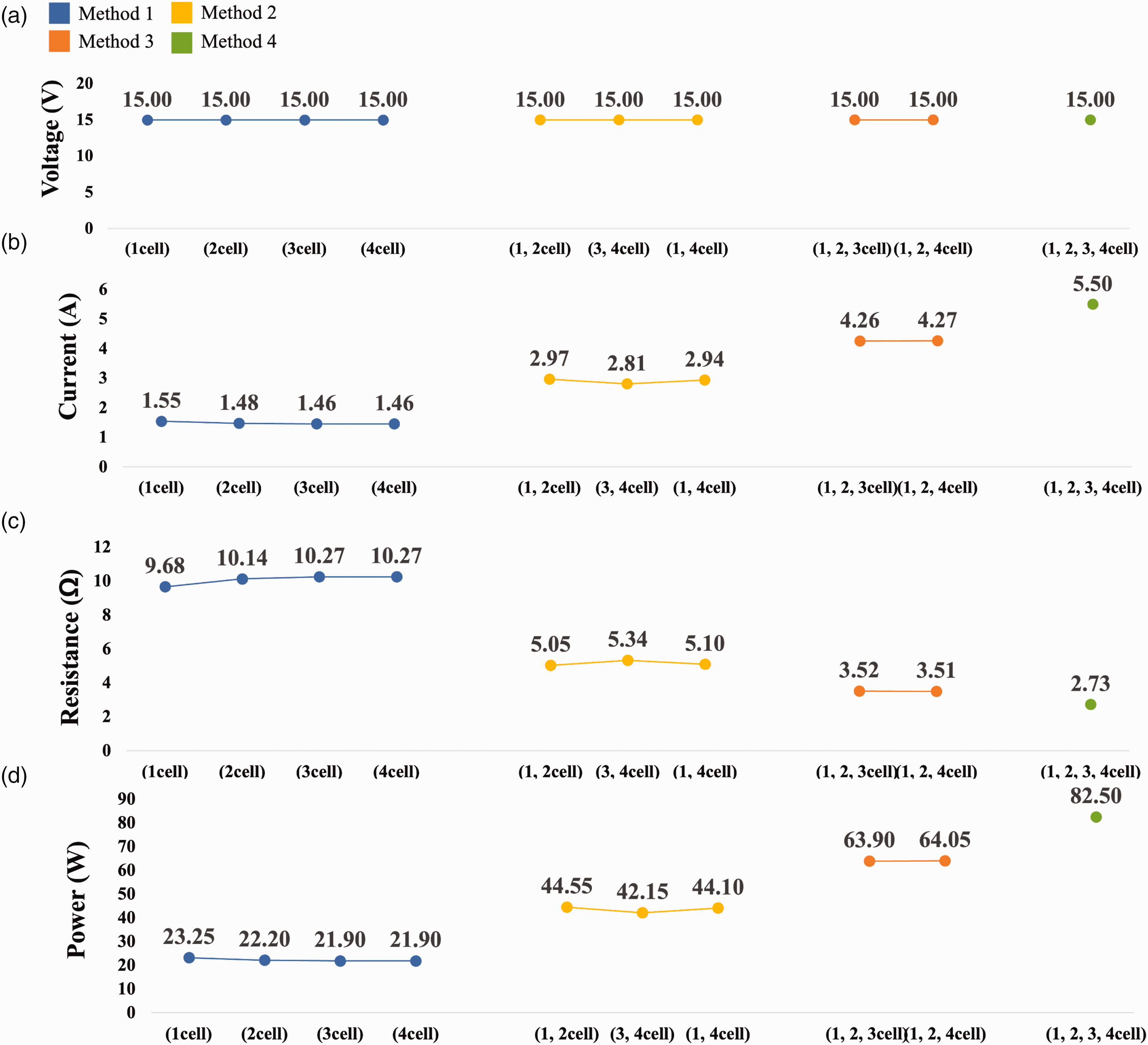
Comparison of electrical characteristic test results of (a) voltage (V), (b) current (A), (c) resistance (Ω), and (d) power (W).
Comparing the voltage (V), current (A), resistance (Ω), and power (W) of the four experimental methods (heating one cell individually and heating two/three/four cells simultaneously), the voltage (V) was the same at 15 V for all four methods. The current (A) increased when multiple cells were operated simultaneously (Figure 4). Compared with when one cell was heated individually, the current increased by 95.4% when two cells were heated simultaneously, by 46.7% when three cells were heated simultaneously, and by 29% when four cells were heated simultaneously.
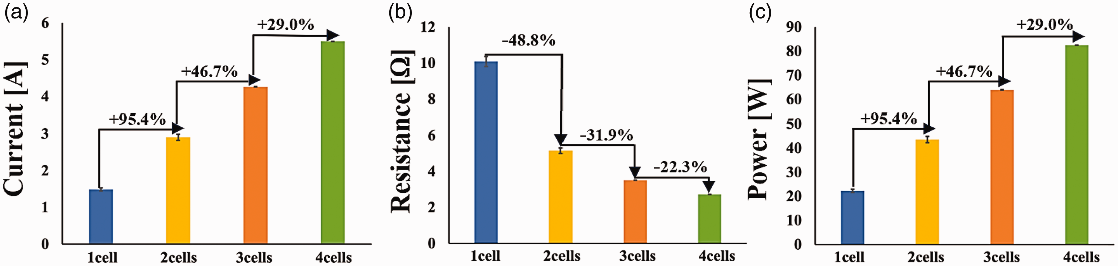
Error bar graph for electrical characteristic tests: (a) current (A), (b) resistance (Ω), and (c) power (W).
Thermal characteristic test results
The resistance (Ω) decreased as more cells were operated simultaneously. Compared with when one cell was heated individually, the resistance decreased by 48.8% when two cells were heated simultaneously, by 31.9% when three cells were heated simultaneously, and by 22.3% when four cells were heated simultaneously. Finally, the power (W) increased as multiple cells were operated simultaneously, with a 95.4% increase when two cells were heated simultaneously, a 46.7% increase when three cells were heated simultaneously, and a 29% increase when four cells were heated simultaneously. These increases corresponded to those for the current (A) values, indicating that electrical energy was consumed as the current increased.
Figure 5 shows the results of the thermal characterization experiments for four methods (one cell each heating, two cells simultaneously heating, three cells simultaneously heating, four cells simultaneously heating), and Figure 6 is the resulting image taken with a thermal imaging camera. Methods 1, 2, 3, and 4 were all conducted in the same environment with a temperature of 22.2°C before heating from 1 cell to 4 cells. The post-heating temperature was found to be 36.3 ≤ 1 cell–4 cell ≤ 38.4°C for all methods, with a difference of only 2°C for each cell. At this time, it was confirmed that the power consumption was required to increase 1°C in the remaining three methods except Method 1, in which it was 0.09 W*100 cm2 · °C in all conditions, which required the same power.
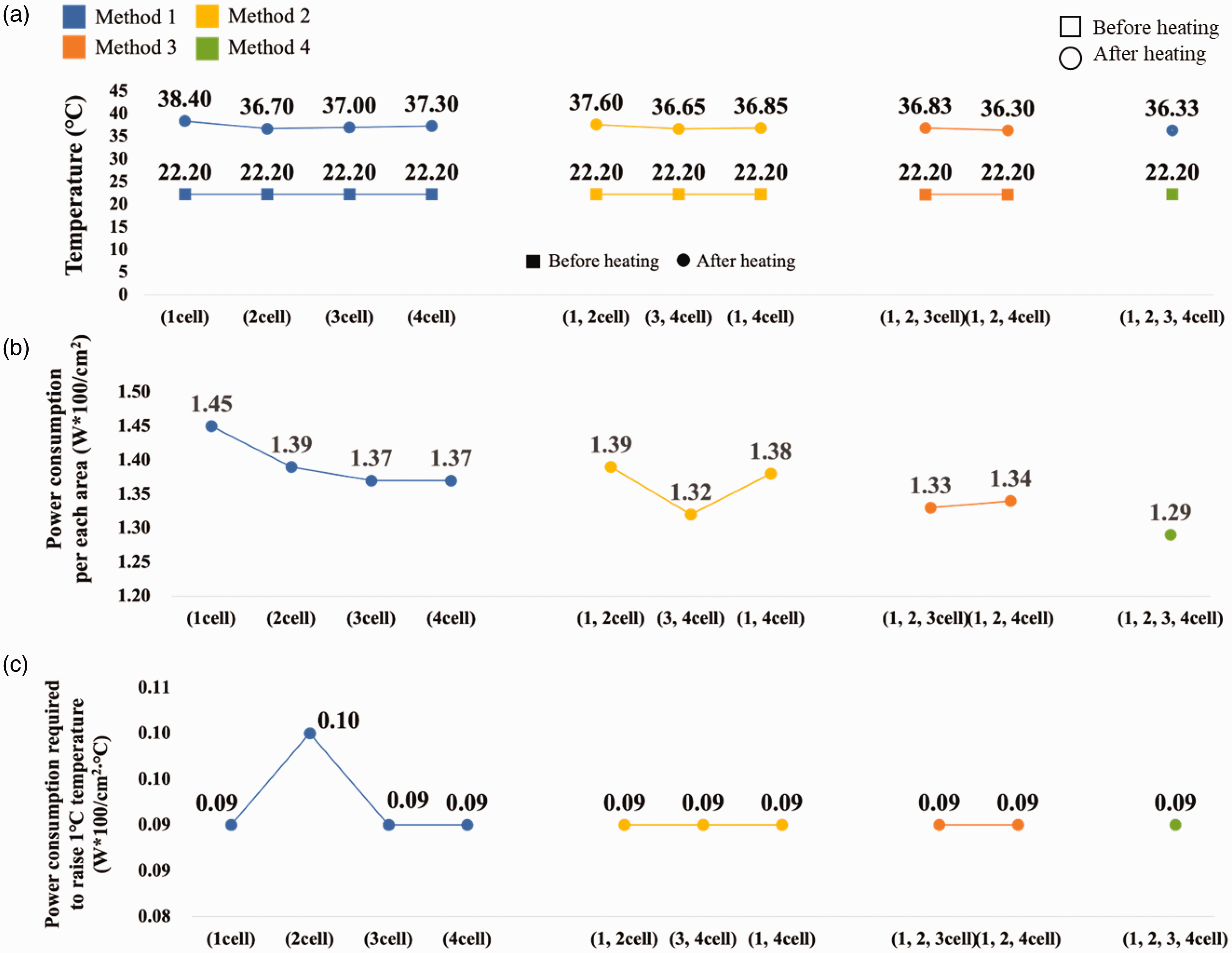
Comparison of thermal characteristic test results of (a) temperature before heating and after heating, (b) power consumption per unit area (W*100/cm2), and (c) power consumption required to raise temperature by 1°C (W*100/cm2∙°C).
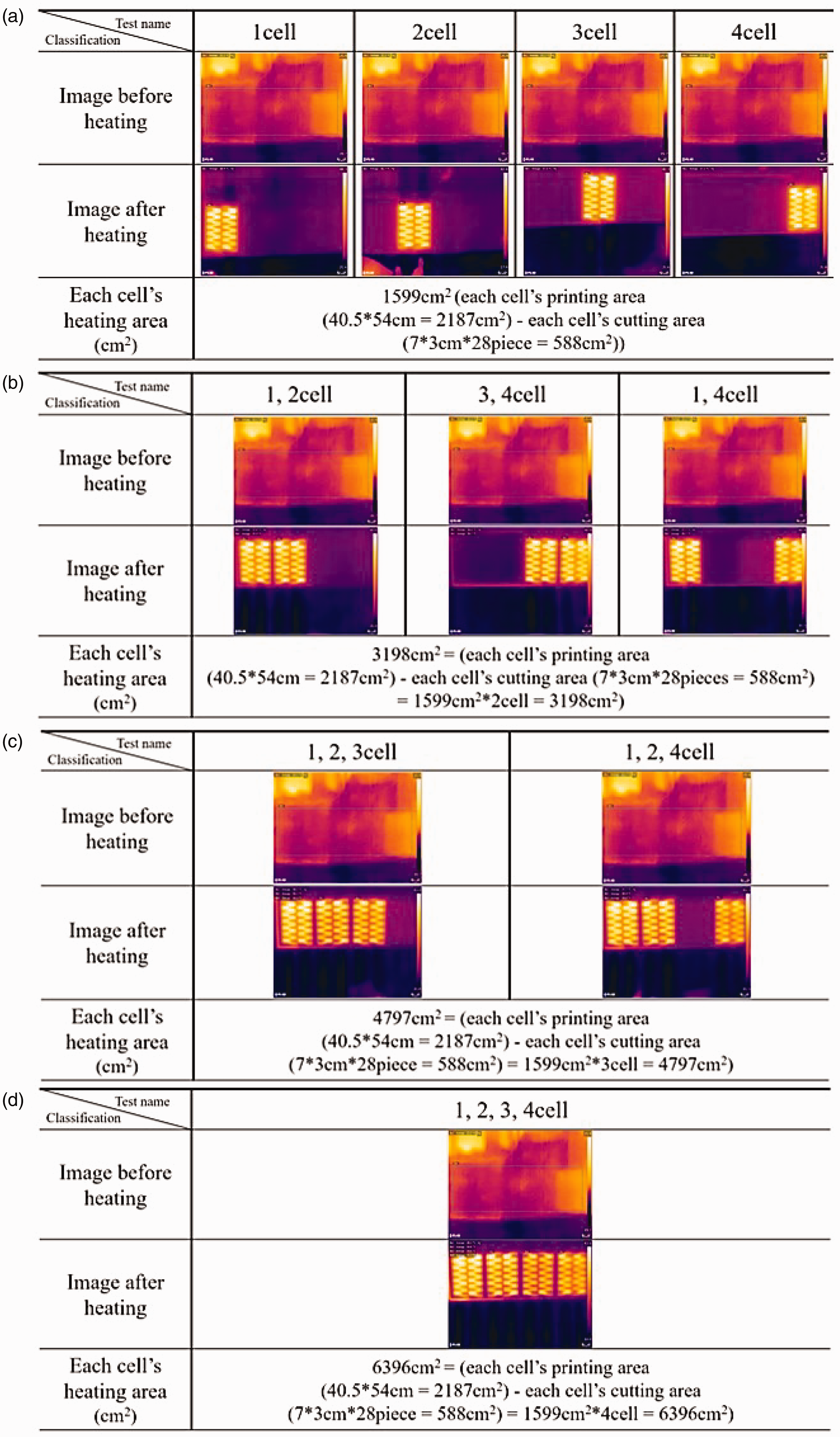
Heating condition of each cell with a thermal imaging camera: (a) Method 1: heating one cell individually, (b) Method 2: heating two cells simultaneously, (c) Method 3: heating three cells simultaneously, and (d) Method 4: heating four cells simultaneously.
The results of the four experimental methods (heating one cell individually and heating two/three/four cells simultaneously) were compared in terms of temperature (°C) before and after heating, power consumption per unit area (W*100/cm2), and power consumption required to raise the temperature by 1°C (W*100/cm2 · °C) (Figure 7). The temperature before heating each cell was measured to be 22.2°C. The temperature after heating showed that the average temperature was consistent with an error of −0.8% to −1.3% when heating each cell, even when operating multiple cells. The average temperature was 37°C or higher when one cell was heated individually and two cells were heated simultaneously, and 36.3°C or higher when three or four cells were heated simultaneously. The power consumption per unit area (W*100/cm2) was 1.29–1.45 W*100/cm2, and even if multiple cells were operated simultaneously, the power consumption error was reduced by 1.23%–1.34%. Finally, the power consumption required to raise the temperature by 1°C (W*100/cm2 · °C) was 0.09–0.01 W*100/cm2 · °C. This result showed a reduction of 2.7% when two cells were heated simultaneously compared with when one cell was heated individually, but all four methods were comparable.
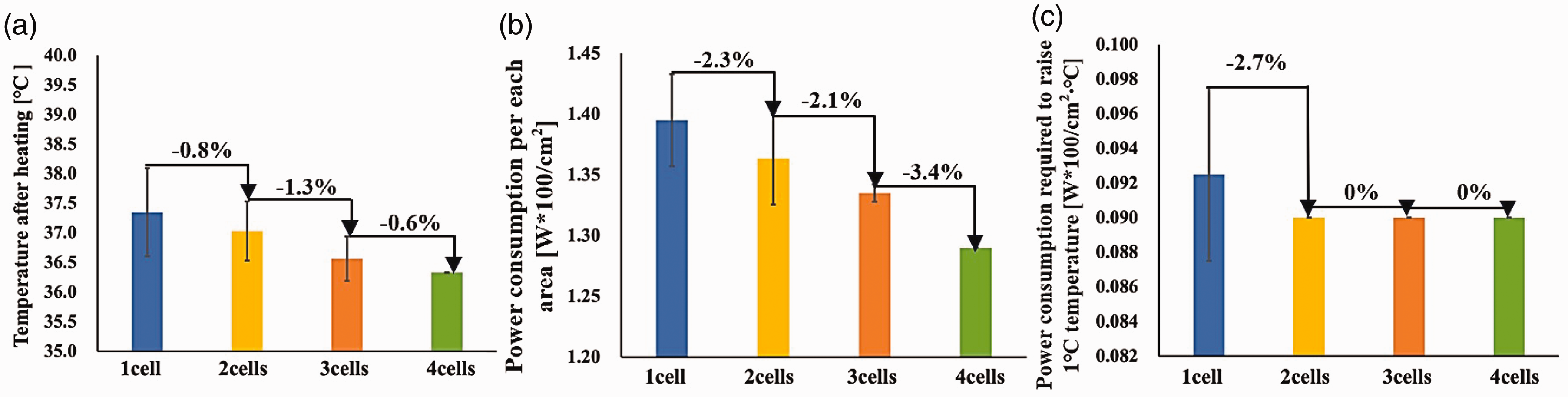
Error bar graph for thermal characteristic tests: (a) Temperature after heating, (b) power consumption per unit area (W*100/cm2), and (c) power consumption required to raise temperature by 1°C (W*100/cm2∙°C).
Experimental results for the third-party samples
The developed cell and the third party samples were heated using the heating wires (Figure 8). The size of the heating area (cm2) was different because commercially available products were purchased. Therefore, the experiments were conducted under different heating area conditions. However, the power densities were the same. The temperature after heating the sample developed in this study was 44°C, which is approximately 10°C–15°C higher than that of the other companies’ samples, and the fastest temperature rise was observed in the sample from this study.
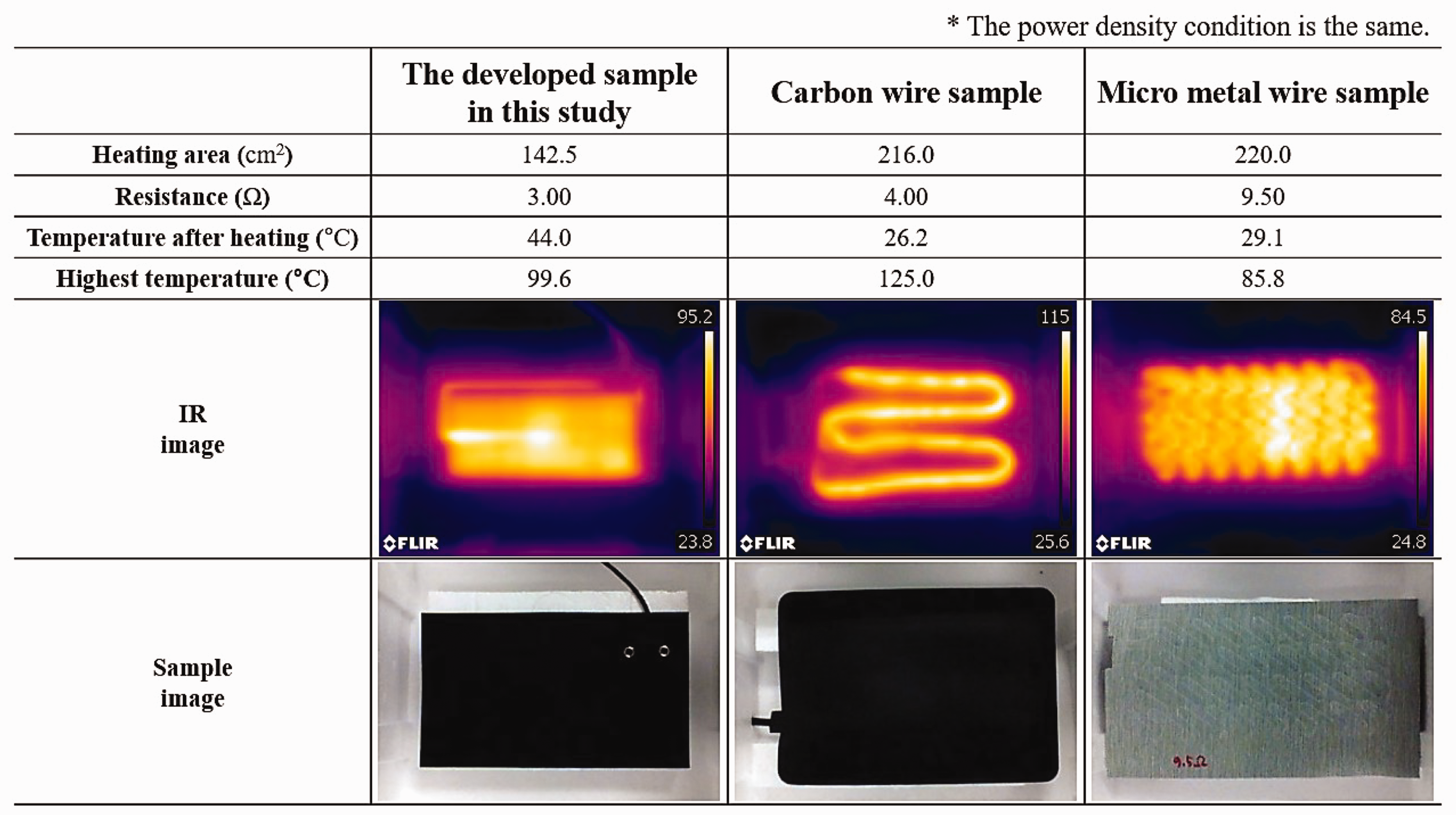
Electrical and thermal results for the sample developed in this study and third-party samples.
The sample developed in this study showed the second highest temperature of 99.6°C in a total heating time of 10 min. However, when the average heating temperature was measured, the sample developed in this study showed the highest temperature of 77.3°C, indicating that it is over 20% more efficient than the other products (Figure 9). In addition, Park et al. 38 stated that a temperature below 100°C is a suitable temperature level for prolonged exposure. Thus, it can be concluded that both the developed sample in this study and the other two products can provide comfort at moderate temperatures; however, the sample developed in this study had the highest average temperature and lowest temperature deviation, exhibiting better thermal efficiency than the other products with heated wires.
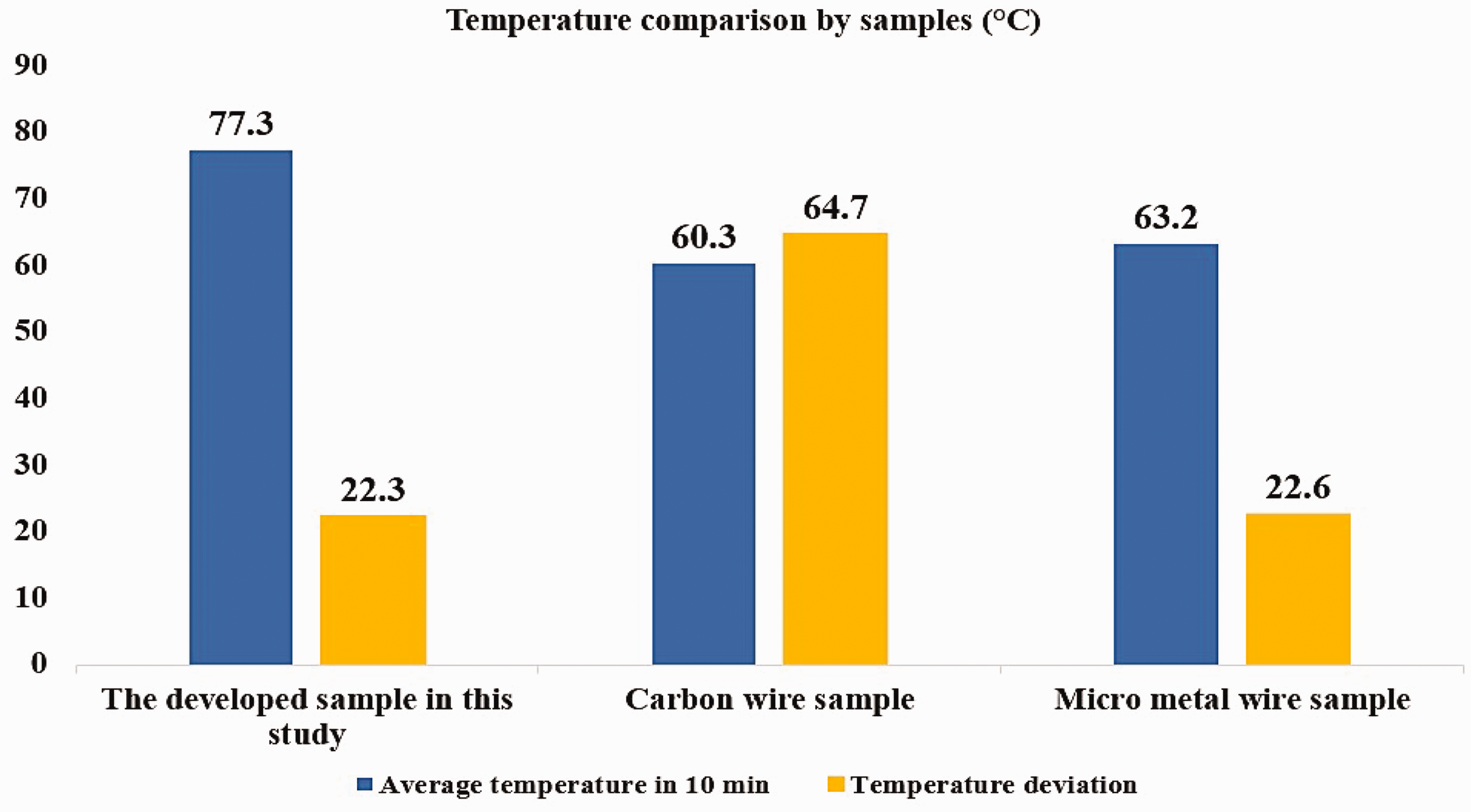
Temperature comparison of samples measured for 10 min.
Discussion
In terms of electrical characteristics, the current (A) increased when multiple cells were operated simultaneously. An increase in the current (A) indicates that electrical energy flows faster through the circuit. At this time, the behavior and response time of the system can be shortened using an electrical device.39,40 The resistance (Ω) decreased, and as resistance hinders the flow of electrical energy, a decrease in resistance (Ω) indicates that current (A) can flow more easily in an electrical circuit.41,42 The power (W) increased, which indicates that, as the number of cells increased, the power (W) increased, and the energy consumption increased. Therefore, it was confirmed that the heating rate and energy can be efficiently utilized.
In the case of thermal characteristics, the temperature after heating (°C) during the heating test was 37°C even if multiple cells were operated simultaneously, and the user can feel thermally comfortable.43 –45 According to Lee et al., 46 the environmental temperature that provides a comfortable sleeping environment is confirmed to be 24–26°C, but as body temperature drops during sleep, it is important to change the temperature such that it can be adjusted rather than maintaining a uniform temperature. Therefore, when the developed CNT-based cells are applied to a sleeping mat, the risk of low-temperature burns and fires can be reduced by adjusting the cell temperature. It is also expected to provide a pleasant and comfortable sleep environment for consumers. The power consumption per unit area (W*100 cm2) of the developed cell was 1.37 W*100/cm2 on average, and the power consumption required to raise the temperature by 1°C (W*100/cm2 · °C) was also consistently 0.09 W*100/cm2 · °C on average; hence, these mats are expected to be highly energy efficient as they require lower power consumption than electric mats or hot water mats.
When comparing the sample developed in this study with other heated mat samples, it was observed that the average heating temperature of the developed sample in this study was more than 20% higher than that of the other samples, and the temperature was the highest; however, the temperature deviation was low. This indicates the advantage of maintaining a constantly high temperature, and we confirmed that the thermal efficiency was much higher than that of the heated mat.
Therefore, in this study, the developed cell was observed to heat up very quickly, used low power for a long time, was adjustable in temperature, maintained a constant temperature, had no cables (unlike heated products), was flexible and free of foreign objects, had a low fire hazard, and was ultrathin (<1 mm) and able to realize various shapes and sizes. This technology is safe and can be used in products, such as electric mats and blankets, which are commonly used in everyday life.
Conclusion
This study aimed to develop and evaluate a CNT planar heater-based low-power heating mat with simultaneous and independent heating functions in user-selected areas using CNT technology. When manufacturing heating mats, the most important aspect is to prevent fires, burns, and electric shock accidents, to enable consumers to safely use them. In addition, if the power consumption is low, these mats are expected to be used more efficiently. It is suggested to consider the safety, functionality, durability, and efficiency when manufacturing heating mats.
The experiments confirmed the electrical and thermal characteristics and evaluated the heating capabilities and energy efficiencies of the selected areas. The results of this study are summarized below. The experiments were divided into four methods to verify the electrical and thermal characteristics. The heating function and energy efficiency of each selected area were evaluated using four methods: heating one cell individually and heating two/three/four cells simultaneously. Samples were produced by applying the technology, and experiments were conducted to compare them with other companies’ products.
The developed power-connected heating mat has the advantage of being flexible, using a coating method rather than a heating wire method with CNT surface heating elements. The advantage of the power connection is that only a rated voltage within 24 V is required for operation. Furthermore, it is made with a structure that does not have any sheathed wires inside the heating element, which minimizes the joints between the heating elements to minimize joint defects, and there is high durability in the form of a surface heating element of 1 mm or less without foreign objects due to the absence of cables on the surface of the mat, which allows various shapes or sizes to be realized with soft touch and elasticity, maximizing comfort. The developed heating mat is energy efficient due to its fast heating rate, which enables heating with low power, thus reducing heating costs.
Therefore, the proposed mat can be used safely. The developed heating mat is highly energy efficient owing to its fast heating rate, which enables heating with low power, leading to a reduction in heating costs. Therefore, considering its high durability, convenient installation, environmental friendliness owing to far-infrared radiation, electricity savings, high safety, and fast but constant heating rate compared with other products, the developed flexible heating element with waterproof coating can be applied to a wide range of products, such as sheets, textiles, clothing, bedding, and heating, as well as mats.
As the demand for technologies using CNTs increases, this CNT surface heating element may be useful as a basic material for producing products using CNTs. However, the developed cell could only be used to conduct durability and safety experiments on samples; therefore, it was not possible to directly assess its pleasantness or comfort for actual users.
Therefore, to produce a product using the developed CNT-coated planar heater, we suggest creating a prototype of the product and recruiting participants to measure thermal comfort. For future studies, it will be necessary to develop a prototype based on this study that considers the aspects of thermal comfort. We compared the results with a third-party heating prototype in this study, and it is planned to compare them with a third-party planar heating element prototype in future research. This study is expected to support the development of low-power heating mats based on CNT planar heaters.
Footnotes
Acknowledgments
We thank FT Lab Members for their support.
Declaration of conflicting interests
The authors declared no potential conflicts of interest with respect to the research, authorship, and/or publication of this article.
Funding
The authors disclosed receipt of the following financial support for the research, authorship, and/or publication of this article: This research was supported by the Institute of Symbiotic Life TECH: Technology, Ecology, Culture, Human.