
Abstract
A mechanical model for the precision winding of yarns was established to address uneven residual tension in wound packages during precision winding. Based on the precision winder, a constant residual tension control method was proposed to ensure uniform residual tension in precision winding, which improved package quality and consistency. A proportional–integral–derivative (PID) control strategy was used to regulate the overfeed roller motor’s speed, and the winding tension was adjusted based on the speed difference between the overfeed and take-up rollers. This ensured consistent circumferential tension of yarns on the inner winding layer, which achieved optimal tensile strength for each layer during precision winding. Compared with constant winding tension control, this method prevented yarn slippage due to negative tension. It also offset the relaxation effect of newly wound yarns on previously wound layers. Packages wound with the constant residual tension had a more stable and uniform winding density than those with the constant winding tension.
In the cotton textile industry, the winding process plays a crucial role: connecting the preparatory procedures before cotton spinning and the processing procedures after cotton spinning. Automatic winders play a crucial role as intermediary equipment between yarn spinning and weaving. Their technological advancements have notably increased production efficiency, diminished labor intensity, and elevated the quality of yarns. 1 With the technological evolution, automatic winders have advanced toward precision winders, which use reciprocating yarn-guiding devices instead of traditional grooved drums for the active transmission of the winding head.2 –6
Increasing value-added demands for various yarns have raised the requirements for yarn-winding systems in spinning equipment.7,8 Significant fluctuations in the yarn tension during winding, caused by both internal and external disturbances, result in uneven winding density and problems such as yarn breakage. These issues adversely affect the quality of the yarn packages and the efficiency in subsequent processing stages.9 –13
To address these issues, various advanced tension control methods have been proposed, including fuzzy proportional–integral–derivative (PID) control, 14 feedforward compensation and internal model controller (IMC) PID control, 15 gray prediction model-based control, 16 and nonlinear active disturbance rejection control (ADRC). 17 In the current work we selected conventional PID control due to its simplicity, robustness, ease of implementation, and proven effectiveness in various industrial applications.
Current winding tension control strategies include constant tension winding18,19 constant torque winding, 20 and taper tension winding.21,22 However, these methods do not address discrepancies between the applied winding tension and actual residual tension within the winding layer.23,24 Constant tension winding results in a loose inner end and tight outer end, 25 while constant torque winding has the opposite effect. 26 Taper tension winding balances these two extremes by adjusting the ratio of the constant tension to constant torque, which results in tension distribution with tight boundaries and loose center. 27 However, these methods overlook the potential effect of the residual tension within the yarn after winding. This oversight increases the probability of yarn breakage and slippage and reduces the load-bearing capacity of the product significantly. 28
This work established a mechanical model for precise yarn winding and proposed a control method to maintain the constant residual tension using PID control. The method adjusted the residual circumferential tension in the inner layer during winding, which ensured uniform tension across all layers. The primary objectives were to achieve optimal tensile strength for each layer and to enhance the uniformity of the winding density. Comparative experiments have been carried out to confirm the efficacy of the proposed method. These experiments aimed to measure the winding density distribution of packages produced using the constant residual tension control, as opposed to the conventional constant tension control. The objective of the work was to showcase the effectiveness of the proposed method in enhancing the uniformity and overall quality of yarn packages. This improvement was expected to lead to superior results in subsequent processing stages (e.g., dyeing).
Mechanical model for the precision-winding process of yarns
Basic assumptions and regulations
The yarn is assumed to consistently remain within its elastic range throughout the winding and forming process of yarns. Based on the theory of elastic stress and the principle of elastic superposition, an analytical expression is derived that correlates residual tension with the winding tension within the packaged yarn.
Assumptions about the model of the wound package should be established before calculating the residual tension of yarns within the wound package. These assumptions should take into account the winding process and the material properties of yarns. The assumptions are as follows.
Yarns in the same winding layer and between different winding layers are not affected by friction within the wound package model. Yarn-winding layers are in close contact with strong stability within the wound package model, with no slipping phenomenon. Any deformation during yarn winding is within the elastic deformation range of yarns in the wound package model, and the bobbin does not undergo plastic deformation. Factors (e.g., yarn volume force, environmental temperature field, and axial force) are not considered during yarn winding.
Based on commonly used calculation parameter symbols, the following provisions are made to represent the parameters in the following text.
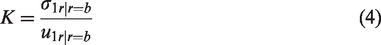
We use
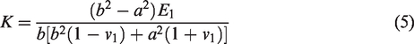
Radial stiffness of the bobbin
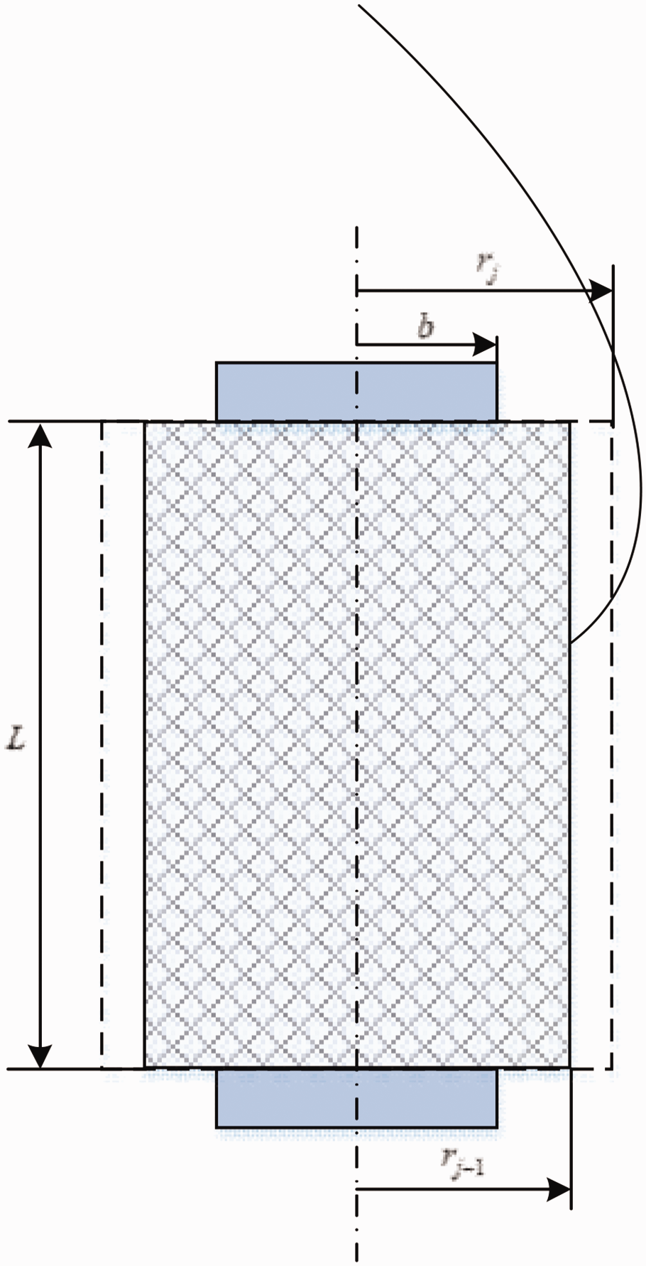
The wound package is considered a cylindrical tube with open ends, disregarding the stress along the package’s axial direction and the deformation unconstrained in the same direction. Here a is the inner radius of the bobbin and b is the outer radius (Figure 1).
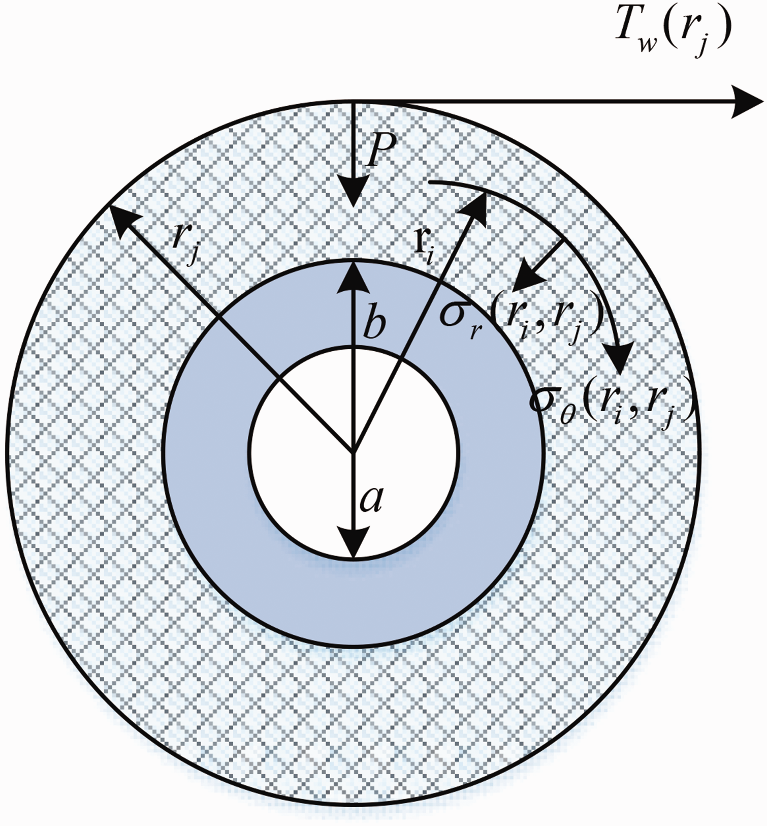
Model of the wound package.
Assuming that the material of the yarn tube is isotropic,
The expressions for the boundary conditions at the inner and outer walls of the spindle are as follows:
The radial stiffness of the spindle is introduced as
Equations (1), (2), and (3) are substituted into equation (4) to obtain the expression for the radial stiffness of the bobbin as follows:
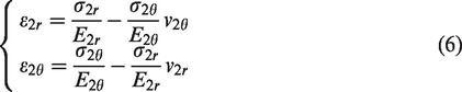
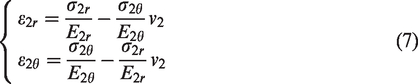
Constitutive equations of the winding layers
The constitutive equations under the plane stress and plane strain can be derived from each other through the transformation of elastic modulus
First, the constitutive equations of the winding layers are as follows under the plane stress:
Ignoring the volumetric force, the internal static equilibrium equation is expressed as follows:
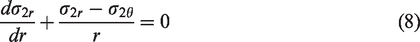
The geometric equation is
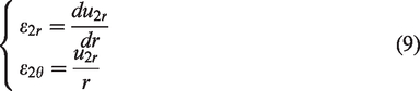
Equations (7) and (9) are used to deduce the strain components, stress components, and displacement components under the plane stress
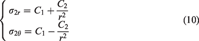

Equations (11) and (12) are used to obtain

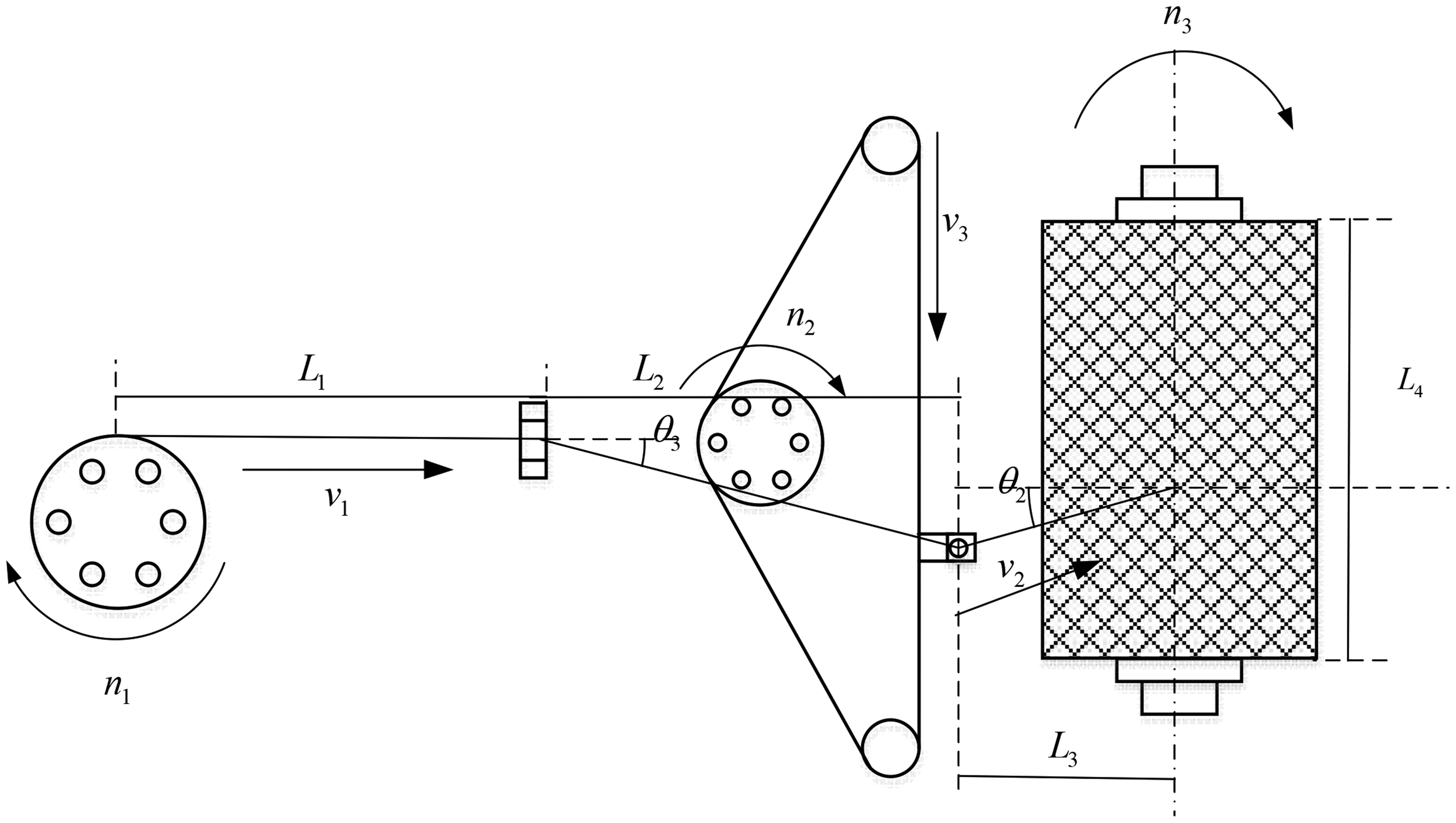
Force analysis of the rewinding section
The yarn is subjected to winding tension
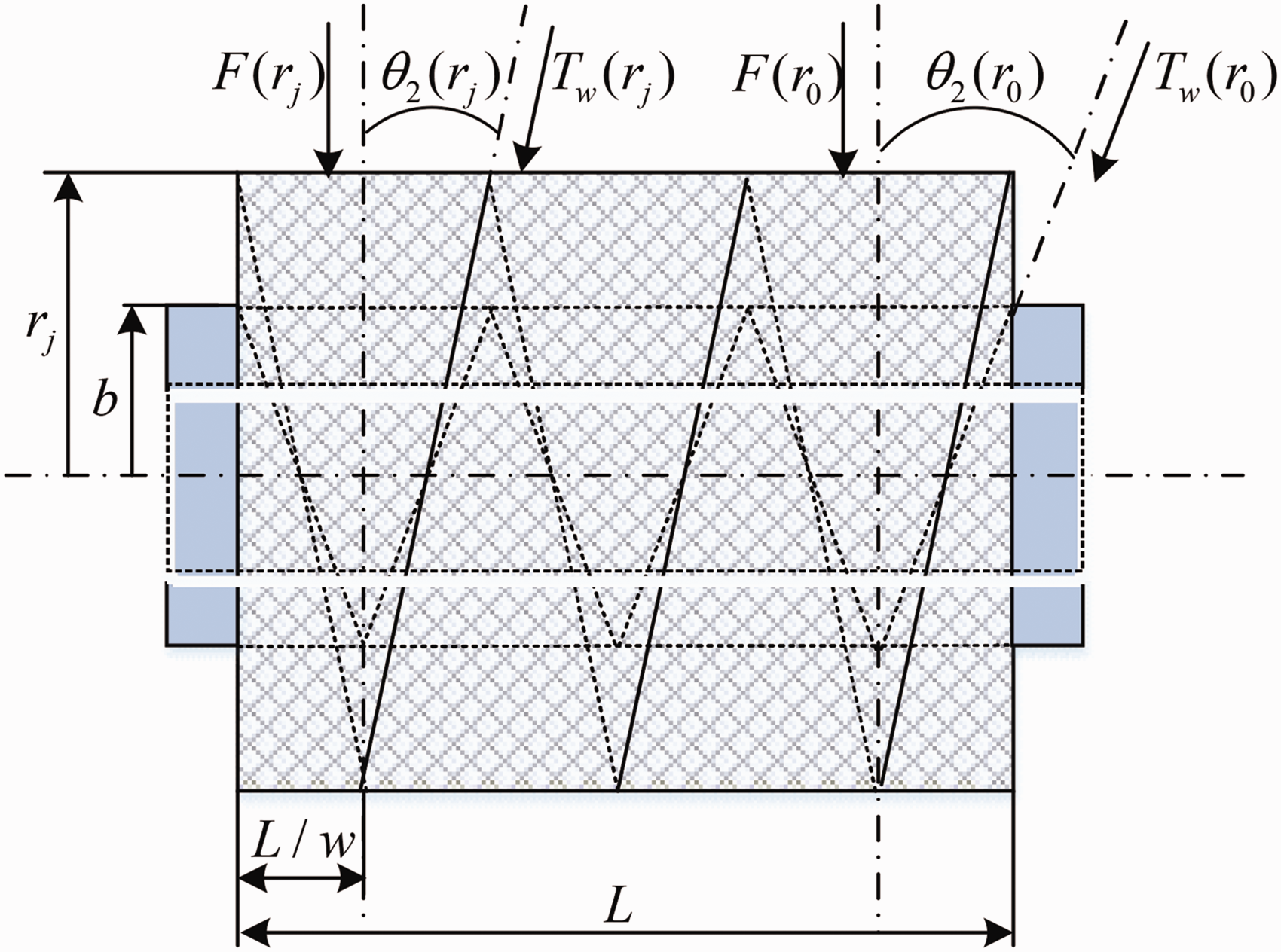
Force conditions at the rewinding section.
During the process of yarn winding,
The winding ratio refers to the number of turns of yarn wound on the bobbin with one reciprocation of the yarn guide. This winding parameter determines the relationship between the winding drive and the movement of the yarn guide. The package length refers to the length of the yarn loaded on the bobbin, and this winding parameter determines the size of the wound package. The winding angle of the yarn is mainly determined by the given winding ratio, package length, and the current winding radius in the same winding process. Assuming constant winding ratio
When the yarn is wound to the jth layer, the winding angle
The winding angle
The winding ratio remains constant in precision winding; the winding angle gradually decreases as the winding radius increases. Consequently, the circumferential winding tension progressively increases under the traditional constant tension control strategy.
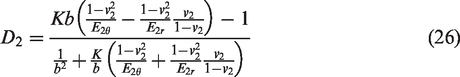
Boundary condition of the wound package winding layer
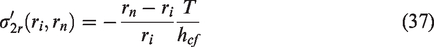
The outer surface of the bobbin is closely attached to the winding layer of yarn during the process of yarn winding. The radial displacement and radial stress of the winding layer on the contact surface both satisfy the continuity condition. Here
The expressions for the boundary conditions at the inner and outer walls of the yarn-winding layer are as follows:
The bobbin and the winding layer satisfy the continuity condition at outer radius
Equations (5) and (17) are substituted into equation (17) to obtain

The internal and external boundary conditions of the yarn-winding layer are defined by
Equations (10) and (13) are substituted into equation (19) to obtain the expression of the general solution coefficient:
Equations (20) is substituted into equation (10) to obtain the expressions for the radial and circumferential stress of the yarn-winding layer during the yarn-winding process:

In equations (20) and (21),
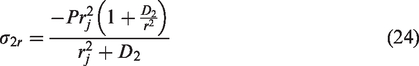

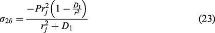
Calculation of the residual tension in the winding layer
Provided that the bobbin undergoes negligible deformation and the tension applied to the winding layers remains within the elastic limit, a mathematical model is formulated based on small elastic deformation and elastic superposition. This model establishes the relationship between the winding tension and residual tension in the yarn-winding layers.
Here
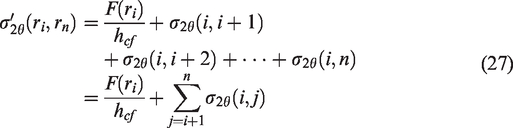
Equation (25) is substituted into equation (27) to obtain
By multiplying both sides of equations (28) by

Equation (14) is substituted into equation (30) to obtain

When the yarn is wound to the nth layer, the total circumferential stress acting on the ith layer is defined by

Similarly, based on the principle of elastic superposition, the expression for the total radial stress acting on the ith layer caused by the winding tension is as follows when the yarn is wound to the nth layer:

Simulation and analysis of winding tension control for the wound package
Yarns made from various materials were employed during the simulation phase, and the radii of the wound package were adjusted to 50, 60, and 70 mm. The aim was to explore the specific influence mechanism of the yarn material and yarn package radius on the residual tension. General patterns were found by adjusting the set constant winding tension. Second, an analysis was conducted on the internal residual tension distribution of the wound package product under the constant winding tension control strategy.
The goal of these simulation steps is to gain a deep understanding of the characteristics of yarn’s residual tension during the winding process and its effect on the overall quality of the wound package. This provides theoretical support and optimization solutions for yarn-tension control, guiding the actual production process to increase efficiency and enhance the quality of the finished product.
Table 1 presents the parameters required for simulation, with yarn-related parameters referring to acrylic and cotton yarn.
Simulation parameters during the yarn-winding process
The expression for the residual tension of the wound package during constant tension winding is derived based on equation (31) under the constant winding tension:

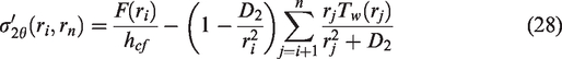
The yarn material, package radius, and the magnitude of the constant winding tension all influence residual tension distribution within the inner layers of the yarn package when a constant winding tension control strategy is adopted (Figures 3(a)–(d)). Although the winding tension is controlled to be constant during the yarn-winding process, the residual tension in the yarn package is not constant. For yarn packages wound with constant winding tension, the subsequently wound yarn relaxes the previously wound yarn, which causes the residual tension of the inner yarn layers to be less than the winding tension. Moreover, the relaxation effect increases with the package radius, which decreases the residual tension from the outer to inner layers of the yarn package.
Distribution of the residual tension of wound packages under the constant winding tension control strategy. (a) Yarn: acrylic, winding radii of 50, 60, and 70 mm and the tension of 10 cN. (b) Yarn: acrylic, winding radius of 60 mm and the tensions of 5, 10, and 15 cN. (c) Yarn: cotton yarn, winding radii of 50, 60, and 70 mm, and the tension of 10 cN and (d) Yarn: cotton yarn, the winding radius of 60 mm and the tensions of 5, 10, and 15 cN.
Precision winding’s rewind section.
Different types of yarns exhibit various relaxation effects (Figures 3(a) and (c)). When the package radius is consistent, the residual tension produced under the same constant winding tension varies considerably. As the package radius increases, the relaxation effect of the later wound yarn on the previously wound yarn becomes stronger. Consequently, the larger the package radius, the greater the difference between the residual tension within the inner layers of the package and the winding tension. It potentially results in negative residual tension. Negative residual tension can easily lead to internal slippage and yarn’s loop detachment during the winding process, which exacerbates instability within the wound package.
A larger constant winding tension enhances the relaxation effect of the latter wound yarn on the former with the same package radius (Figures 3(b) and (d)). This leads to a more significant change rate in the residual tension of the inner yarn and a larger difference in the residual tensions between the inner and outer yarn layers.
The material properties of the yarn are not fully utilized under the constant winding tension control strategy. This results in an uneven distribution of residual tension within the wound package and the potential for negative residual tension, which causes yarn slippage and adversely affects the quality of the finished yarn package. In addition, the relaxation effect between yarn layers can cause the yarn arrangement within the package to be less compact, which contributes to an uneven winding density distribution.
Implementation of the constant residual tension for yarns
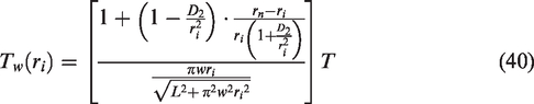
Calculation of yarn-winding tension distribution for the constant residual tension
Assuming that the residual tension in the yarn-winding layers remains constant after yarns are wound. Here 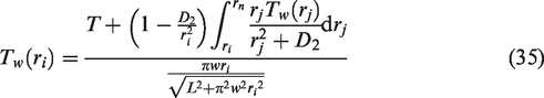
When 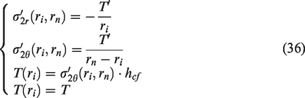
Equations (33) is substituted into equation (37) to obtain

Therefore,
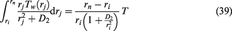
Equation (39) is substituted into equation (35) to obtain
Yarn-winding tension model based on Hooke’s law
According to Hooke’s law, force and strain on the yarn exhibit a linear relationship during winding:
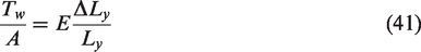
Here 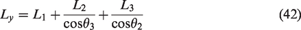
Yarn elongation 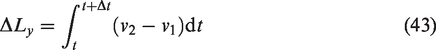
Then the winding tension of yarns in the rewound section is defined by
The yarn guide roller drives the yarn guide to reciprocate through the steel wire rope and inert guide roller. Therefore, yarn guide’s movement speed 
Equation (45) is substituted into equation (44) to obtain
Based on the above analysis of mechanical structure, mechanical structural factors
Design of the PID tension control system
The yarn-tension control system should account for a variety of uncertainties during the winding process, particularly those influencing unwinding tension. It is crucial to minimize the effect of factors such as unwinding dynamics and yarn-guiding movements. In the rewind section, yarn-winding tension is influenced by the speed difference between the overfeed motor and the take-up motor, both of which can be directly adjusted by the system. Therefore, the effective control of yarn pretension can be achieved by regulating the speed difference between these two motors, a method that is straightforward to implement.
The closed-loop control of the yarn tension necessitates the selection of an appropriate control algorithm to manage the overfeed motor’s speed; therefore, the yarn-winding tension is adjusted as needed. The conventional PID control method is employed in the work, utilizing a PID controller to adjust the overfeed motor’s speed in real-time.
The traditional PID control algorithm consists of proportional coefficient
Figure 5 shows the traditional PID control system structure. Here
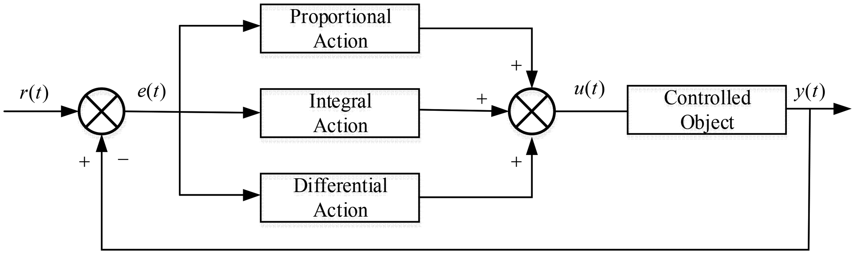
Traditional PID control system structure.
The core principle of a conventional PID control system involves separately executing proportional (P), integral (I), and derivative (D) operations on the input signal. The outcomes of these operations are then linearly integrated to produce the output. The process can be described as follows:

Assuming that 
Here 

Equation (49) represents the incremental PID algorithm. The kth value of this control algorithm is related to the input signals at the kth, (k – 1)th, and (k – 2)th sampling time of the control system, applying respective weighting to each. This approach reduces the computational load on the processor significantly and minimizes the risk of integral saturation, which limits the output only when necessary.
Experiment
Design of calculation method for winding density
The winding density of a yarn package refers to the mass of yarn per unit volume within the package. To obtain the distribution of winding density within a package yarn, it is necessary to measure the winding density at various radial positions within the inner layers of the package. In a precision-winding system, measuring the winding density in an inward-to-outward sequence is relatively difficult. Therefore, this paper adopts the method of unwinding a formed package and measuring the winding density from the outside to the inside based on the reduction in yarn mass and package radius. A schematic diagram of the unwinding process of the yarn package is shown in Figure 6.
Model of the yarn-unwinding process.
When the yarn layers of the package are unwound down to the jth layer, the total mass of the package at this time is obtained by the weighing sensor, and the yarn package is kept in the unwinding state. After a unit time 
Experimental platform construction
Figure 7 illustrates the precision-winding experimental platform to achieve consistent yarn packages with controlled winding and residual tension. The platform included components, e.g., an overfeed roller, take-up roller, yarn guide mechanism, and sensors. The rotational speed of the overfeed roller was adjusted in real-time by a PID controller to regulate the yarn-winding tension.
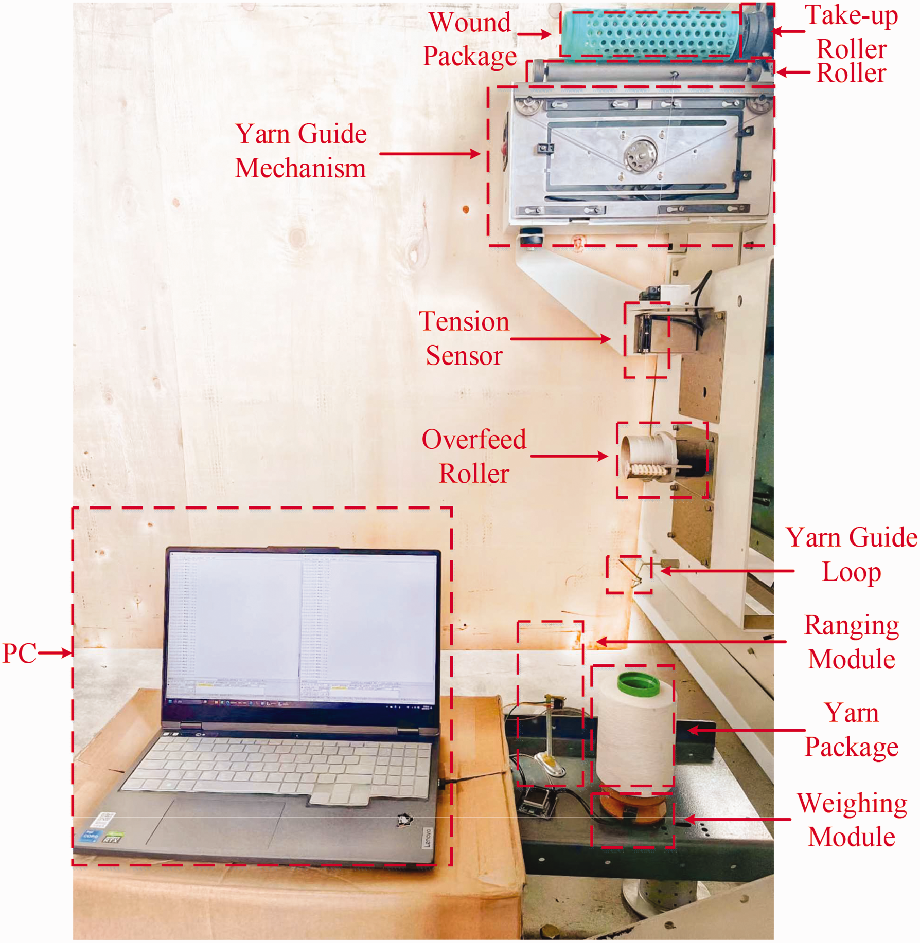
Precision-winding experimental platform and winding density measurement platform.
A platform for measuring winding density was developed to assess the distribution of internal density within the wound package. This setup included a weighing module and a ranging module, which continuously monitored the radius and mass of the yarn package during the unwinding process. Sensor data were collected using the 485-communication protocol and transmitted to a PC host computer for analysis. Mass and distance data were exported, tabulated, and computationally processed to obtain the winding density at various yarn-package radii during unwinding.
The tension sensor operated at a sampling frequency of 10 Hz, with tension sensor’s accuracy at 0.01 cN. The weighing sensor operated at a sampling frequency of 1 Hz, with tension sensor’s accuracy at 1 g. The ranging sensor operated at a sampling frequency of 1 Hz, with tension sensor’s accuracy at 0.1 mm.
Measurement and processing of experimental data
The precision-winding experimental setup was used to create yarn packages with defined parameters: the outer radii of the bobbin and wound package were 29 and 38 mm, respectively. The experimental setup was configured to apply constant winding tensions of 5 and 10 cN, in addition to maintaining constant residual tensions of 5 and 10 cN. Subsequent unwinding experiments were conducted, and data were collected using the measurement platform for the yarn-package winding density.
Experimental data were processed on a host computer to analyze the internal density distribution of the yarn package. Specifically, equation (40) was used to calculate the required winding tension for yarn packages formed under the constant residual tension during the winding process. The actual tension experienced by the yarn package during winding was measured by the tension sensor (Figure 8).
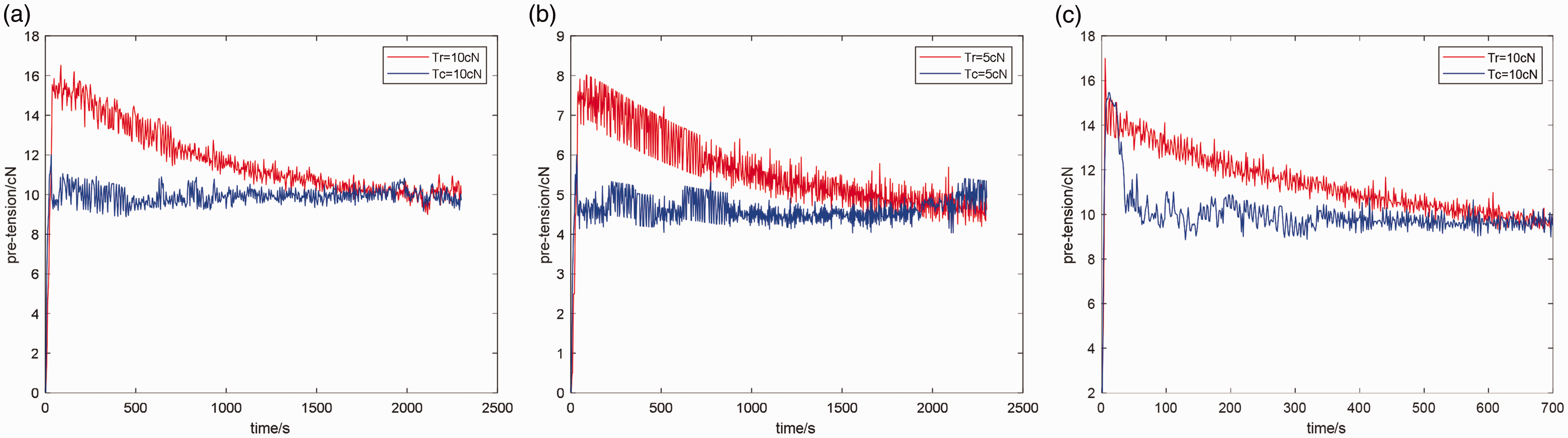
Tension variation curves of the yarn during the winding process under the constant residual tension and constant winding tension control. (a) Tension variation curves of the acrylic yarn with a target tension of 10 cN during winding. (b) Tension variation curves of the acrylic yarn with a target tension of 5 cN during winding and (c) Tension variation curves of the cotton yarn with a target tension of 10 cN during winding.
Figures 9 –14 and Tables 2 –4 show collected data obtained through the experiment.
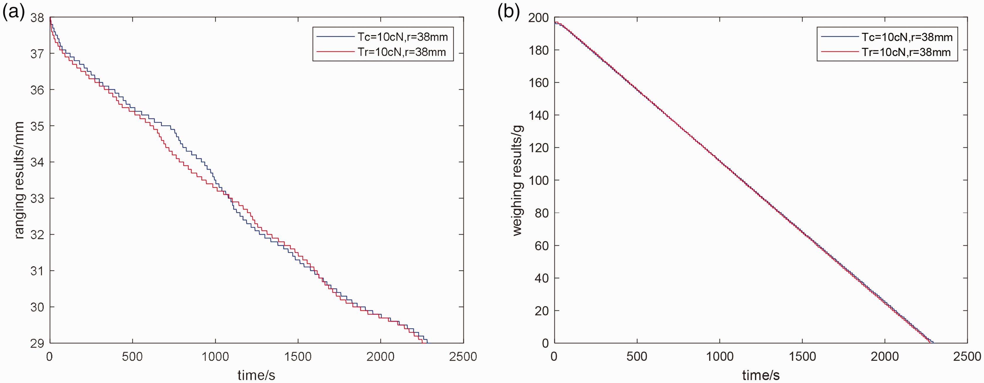
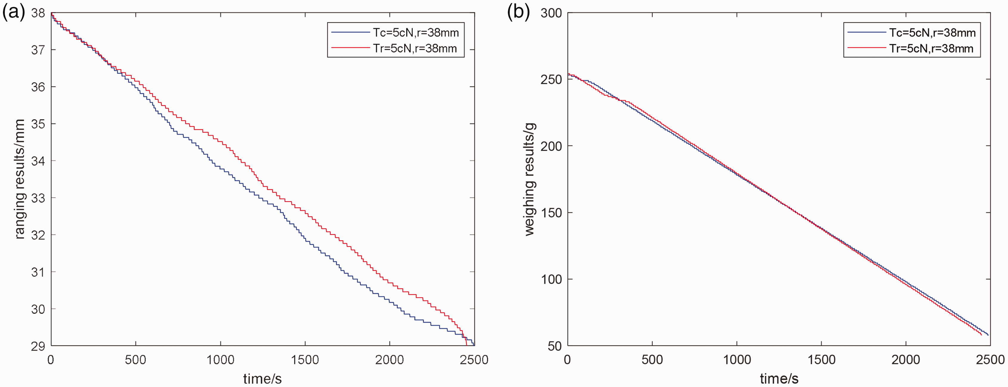
Collected data from the unwinding experiment of the acrylic yarn packages with a target tension of 10 cN during the winding process: (a) real-time measurement data from the ranging module during the yarn-unwinding experiment, while the yarn packages are formed with a constant winding tension of 10 cN and a constant residual tension of 10 cN separately during the winding process and (b) real-time measurement data from the weighing module during the yarn-unwinding experiment, while the yarn packages are formed with a constant winding tension of 10 cN and a constant residual tension of 10 cN separately during the winding process.
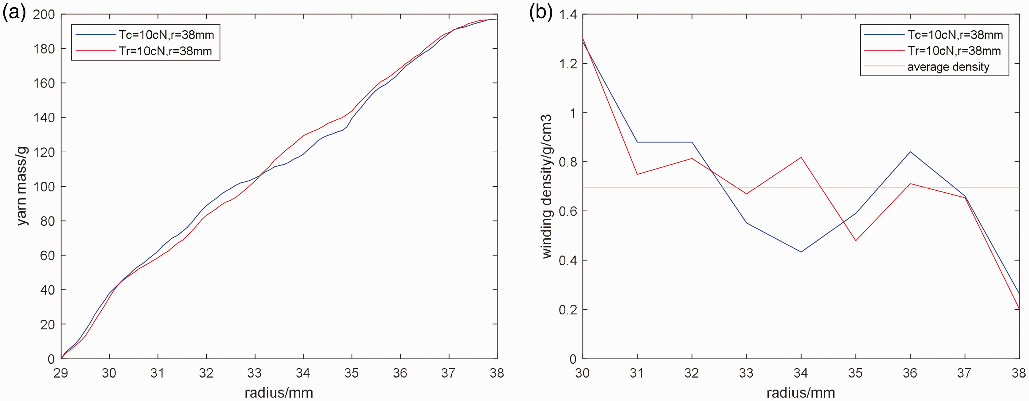
Data obtained after the mathematical processing of the data. (a) Yarn mass distribution of acrylic yarn packages with a constant winding tension of 10 cN and a constant residual tension of 10 cN during the winding process and (b) Winding density distribution and average density of acrylic yarn packages with a constant winding tension of 10 cN and a constant residual tension of 10 cN during the winding process.
Collected data from the unwinding experiment of the acrylic yarn packages with a target tension of 5 cN during the winding process: (a) real-time measurement data from the ranging module during the yarn-unwinding experiment, while the yarn packages are formed with a constant winding tension of 5 cN and a constant residual tension of 5 cN separately during the winding process and (b) real-time measurement data from the weighing module during the yarn-unwinding experiment, while the yarn packages are formed with a constant winding tension of 5 cN and a constant residual tension of 5 cN separately during the winding process.
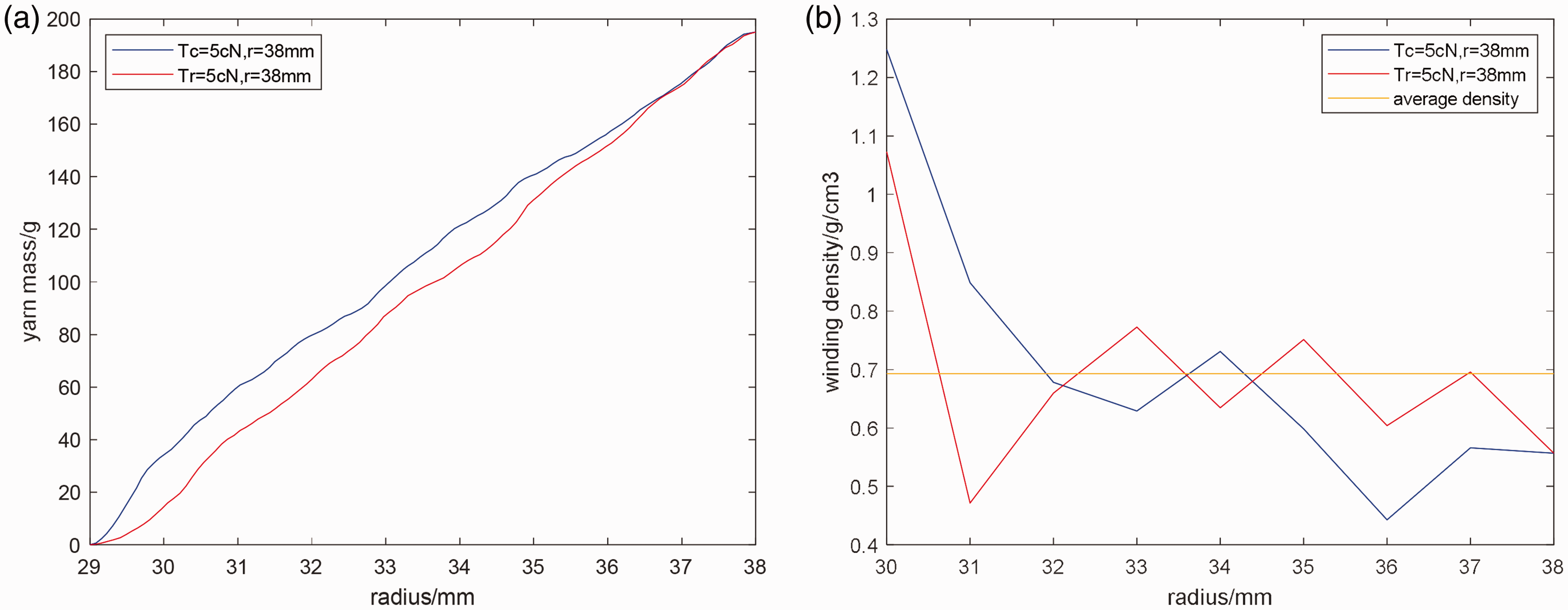
Data obtained after the mathematical processing of the data. (a) Yarn mass distribution of acrylic yarn packages with a constant winding tension of 5 cN and a constant residual tension of 5 cN during the winding process and (b) Winding density distribution and average density of acrylic yarn packages with a constant winding tension of 5 cN and a constant residual tension of 5 cN during the winding process.

Collected data from the unwinding experiment of the cotton yarn packages with a target tension of 10 cN during the winding process: (a) real-time measurement data from the ranging module during the yarn-unwinding experiment, while the yarn packages are formed with a constant winding tension of 10 cN and a constant residual tension of 10 cN separately during the winding process and (b) real-time measurement data from the weighing module during the yarn-unwinding experiment, while the yarn packages are formed with a constant winding tension of 10 cN and a constant residual tension of 10 cN separately during the winding process.
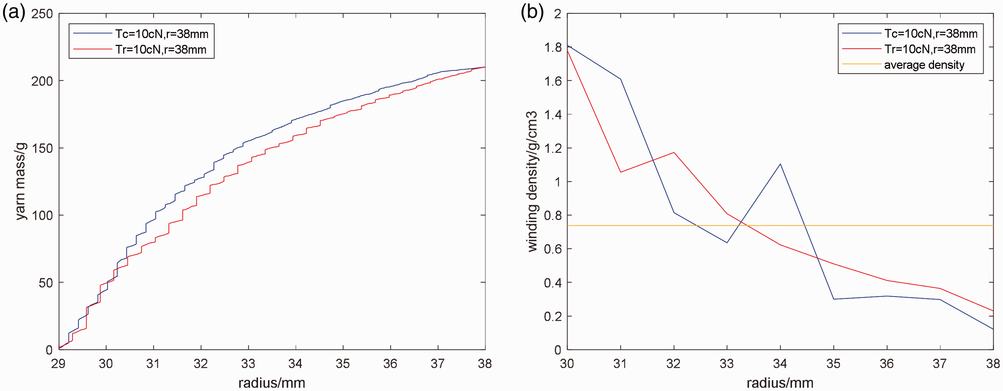
Data obtained after the mathematical processing of the data. (a) Yarn mass distribution of cotton yarn packages with a constant winding tension of 10 cN and a constant residual tension of 10 cN during the winding process and (b) Winding density distribution and average density of cotton yarn packages with a constant winding tension of 10 cN and a constant residual tension of 10 cN during the winding process.
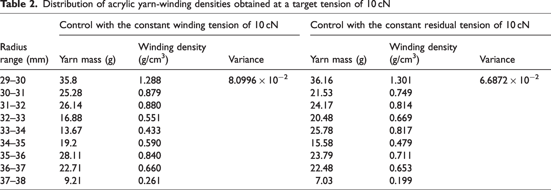
Distribution of acrylic yarn-winding densities obtained at a target tension of 10 cN
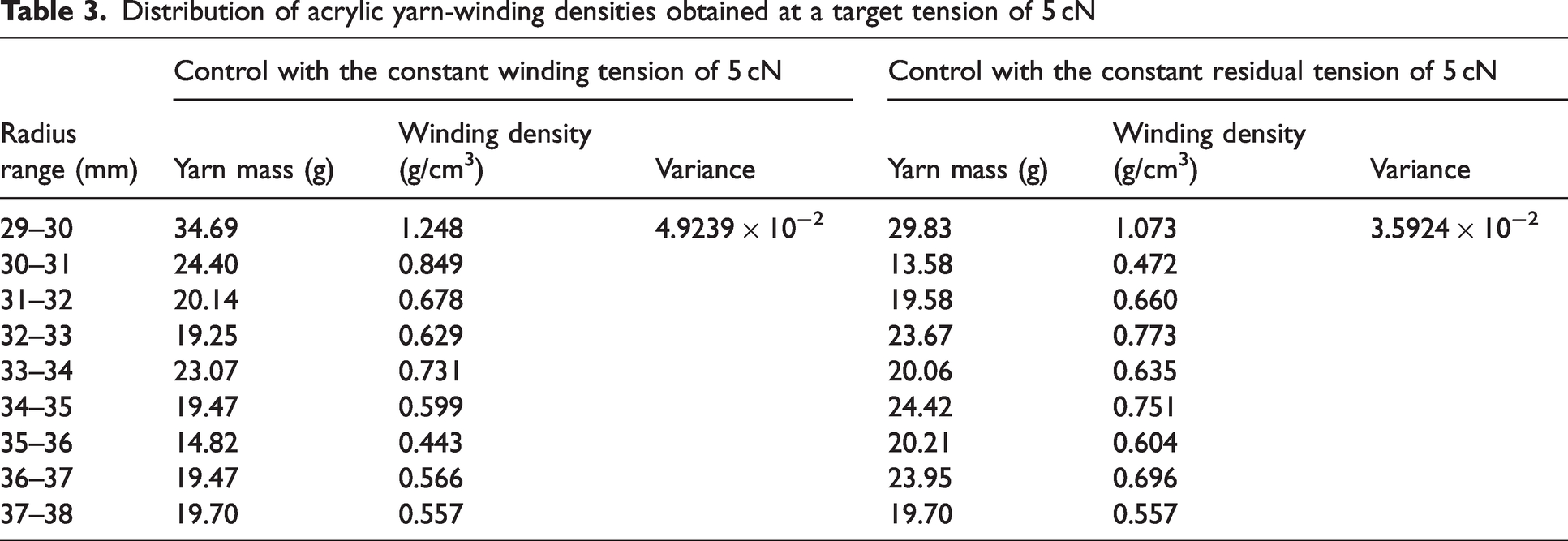
Distribution of acrylic yarn-winding densities obtained at a target tension of 5 cN
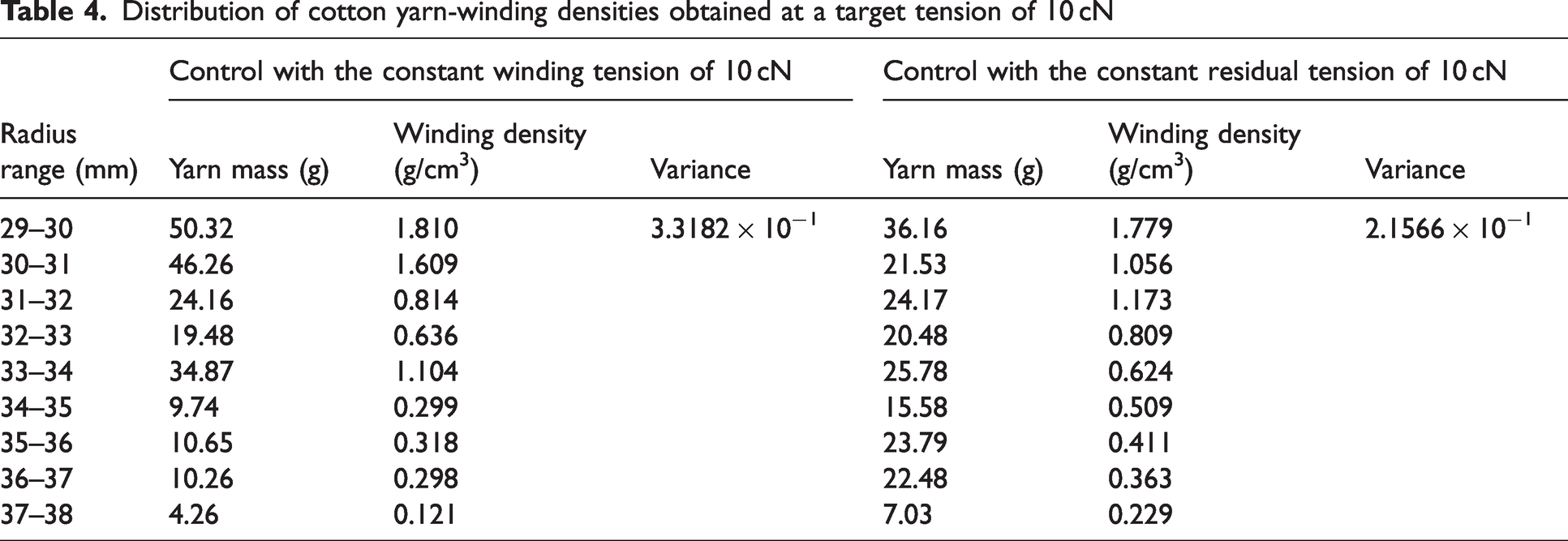
Distribution of cotton yarn-winding densities obtained at a target tension of 10 cN
Figures 9(a), 11(a), and 13(a) demonstrate that the distances recorded by the ranging module for the yarn packages produced with both the constant winding tension and constant residual tension exhibit a roughly linear increase under a constant target tension, which is directly proportional to the duration of unwinding. However, the changing rate of the ranging results during the unwinding process is not constant and exhibits fluctuations. Specifically, compared with yarn packages formed under the constant residual tension, those formed under the constant winding tension demonstrate a more pronounced fluctuation in the changing rate of the ranging results.
The yarn weighing mass of both yarn packages formed under the constant winding tension and constant residual tension shows a linear downward trend with increased unwinding time under the constant target tension (Figures 9(b), 11(b), and 13(b)).
Data collected from Figures 9, 11, and 13 in the experiments are processed in depth. First, the ranging results and weighing results of the same unwinding time are precisely matched to ensure the synchronization and accuracy of data. Second, the total mass of the yarn package is processed by subtracting the mass of the bobbin to reflect the actual mass distribution of the yarn packages, and the ranging results are converted into real-time unwinding radii. This helps to intuitively understand the distribution status of yarns inside the yarn packages. Yarn mass distribution inside the yarn packages (Figures 10(a), 12(a), and 14(a)) is obtained, presenting the specific quantitative relationship between yarn mass and unwinding radius. Finally, winding density distribution inside the yarn packages (Figures 10(b), 12(b), and 14(b)) are calculated.
Both yarn packages formed under the constant winding tension and constant residual tension decrease yarn mass with the decreased real-time unwinding radius under constant target tension, showing an approximately linear pattern with some fluctuations (Figures 10(a), 12(a), and 14(a)). Comparatively, the yarn-mass variation rate in packages formed under the constant residual tension shows subtler fluctuations and a trend closer to linear change.
Internal density distribution shows complex characteristics due to multiple factors in precision winding (Figures 10(b), 12(b), and 14(b)). Although the general trend shows a progressive decrease in the winding density from the center to the periphery, both yarn packages produced with constant winding tension and constant residual tension exhibit significant variations in their internal winding density distribution. The variance in winding density distribution is smaller in constant residual tension yarn packages under the constant target tension compared with the packages under the constant winding tension (Tables 2 –4). Constant residual tension control can achieve more uniform winding density distribution to a certain extent, and the effectiveness of constant residual tension control varies with the target tension and the type of yarn. Under the condition of the same target winding radius, when the yarn type is acrylic, constant residual tension control optimizes the variance of winding density distribution by 17.44% and 27.04%, respectively, at the target tensions of 10 cN and 5 cN, and when the yarn type is cotton, constant residual tension control optimizes the variance of winding density distribution by 35.01% at the target tension of 10 cN. These findings underscore the practical significance of constant residual tension control in production.
Conclusion
The precision winder was adopted as the primary research focus, and an in-depth analysis was performed for the mechanical model of the yarn during precision winding. Small elastic deformation and elastic superposition were used to establish an analytical relationship between the residual tension and winding tension within the yarn-winding layers. A yarn-winding control method was proposed to maintain constant residual tension and address issues such as yarn breakage, slipping, and uneven winding density distribution prevalent in traditional constant winding tension methods.
The main contributions of this work are as follows.
The mechanical model of the yarn precision-winding process was used to analyze the influencing factors of the residual tension within the yarn package during precision winding. Key factors included yarn material properties, yarn package radius, and yarn-winding tension. Even with a constant winding tension controlled, the residual tension within the yarn package fluctuated due to the relaxation effect of the outer yarn layers on the inner layers, which intensified with the increased winding radius. Based on elastic stress theory, a control method for the yarn-winding process was proposed to maintain constant residual tension. This method involved setting a precise target value for the residual tension and integrating it with various parameters of the yarn package and yarn. A precise relationship between the required yarn-winding tension for precision winding and its real-time winding diameter was established under the constant residual tension. Real-time adjustments in winding tension ensured the constant residual tension within the yarn package. Furthermore, a specific implementation method was outlined for achieving and controlling the constant residual tension in the yarn. A precision-winding experimental platform and winding density measurement platform were established. Unwinding the yarn package and measuring its winding density layer by layer from the outer to the inner layers provided insights into internal winding density distribution. For yarns with the same type, yarn packages formed under the constant winding tension and constant residual tension exhibited characteristic fluctuations in internal winding density distribution, generally decreasing from inner to outer layers. Constant residual tension control was found to enhance the uniformity of winding density distribution in the wound package compared to constant winding tension control, and this optimization effect is related to the type of yarn and the target tension.
Footnotes
Declaration of conflicting interests
The author(s) declared no potential conflicts of interest with respect to the research, authorship, and/or publication of this article.
Funding
The author(s) disclosed receipt of the following financial support for the research, authorship, and/or publication of this article: This work is funded by National Key Research and Development Program of China (grant number 2023YFB3210901), Zhejiang Province Public Welfare Technology Application Projects of China (grant number 2017C31036), 151 Talent’s Projects of Zhejiang Province (grant number 11130031511703), and National Natural Science Foundation of China (grant number 11872337).