
Abstract
Loop yarn is a typical fancy yarn composed of three strands and differs significantly from conventional yarn. The loop yarn also suffers from friction and wear during use and processing. To create a unique fuzzing effect, loop yarn is usually sanded by rubbing against an abrasive. The frictional force and coefficient can only roughly reflect the frictional effect between yarn and abrasive, and it is challenging to represent the amount of contact between the two at the microscopic level. A Hertz contact model is first established to evaluate the contact between the loop yarn and the abrasive. This paper derives the calculation formula for the contact number and area between the loop yarn and the abrasive. The calculation results indicate that as the mesh of the abrasive increases, the frictional force and coefficient decrease, the contact number between the loop yarn and the abrasive gradually increases, the contact area first increases and then tends to stabilize, and the contact force and stress decrease and stabilize. The ratio of the fiber distribution force to its contact area can be used as an evaluation index for fiber wear resistance. The product of the square root of contact number, abrasive particle radius, and friction index can provide feedback on friction performance.
Fancy yarn is a particular strand composed of three or more single yarns. The differences in raw materials, color coordination, linear density, and twists can give fancy yarn some style. Loop yarn is a typical fancy yarn widely used in clothing and home textile products. The loop yarn is also accompanied by friction or abrasion during wearing and processing. Due to its structure being different from ordinary yarn, the abrasion appearance of the loop yarn is also distinct. After wearing, the fibers of the loop yarn fracture, and the hairiness significantly increases. 1 To produce the fuzzing or sanding yarn, 2 some technical people drew the loop yarn sliding over the corundum abrasive surface 3 in the twisting machine.
Many fibers are wrapped and twisted into yarn, and their apparent morphology is related to the fiber shape and wrapping structure. The fiber arrangement, structure gaps, and distribution characteristics determine that the yarn appearance is not uniform and smooth but instead a deformable rough body. In production and daily use, friction between yarns, between yarn and device, and between yarn and fluid can all cause a change in appearance through several fiber rearrangements, loss, or thinning.
El Mogahzy and Gupta 4 proposed that fibers contact only at the irregular tips of their surface, and the more irregular tips per unit area, the smoother or lower roughness of the fiber. According to the size of the fiber inside the yarn, the geometry between fibers or yarns belongs to the spatial shape line, while the contact between fibers inside the yarn is point or line segment contact. Ning 5 discovered three friction forms on the surface and inside of a rope: point, line, and surface. The fibers would undergo cyclic friction and fracture, inducing many short fibers and nonperiodic surface hairiness. The contact between yarn and part varies depending on physical conditions and can be multipoint or point-line mixed contact. The part’s surface is more or less uneven, and the contact between the fibers and the part is mostly point contact.
The contact theory can determine the contact number and area between the fiber and the part to explain the contact mechanism. Hosseinali and Thomasson 6 designed a Matlab function to calculate the number of fibers in a cotton fiber assembly and its contact area with a smooth surface in the maximum elastic deformation. Cornelissen et al. 7 used a geometric contact model of cylinder and plane for simulating fiber tow–metal contact, and proposed that the surface topography of the counterface was the main parameter affecting the friction behavior. The contact of fiber tows and metal almost remained fully elastic deformation behaviour. Wu et al. 8 calculated the fiber contact number under normal load by the cross-sectional parameters of carbon fiber and the fiber contact area by the Hertz contact model of the cylinder and plane, then established a mathematical relationship between the normal load and the contact area. Cornelissen et al. 9 used the Maugis–Dugdale adhesive contact and general Hertzian elliptic contact model to calculate the fiber–fiber contact area, and proposed that the model is investigated both with and without adhesive. Che et al. 10 used the Hertz theory and Johnson–Kendall–Roberts (JKR) theory to calculate the contact area of the fiber tows and the spools, also proposed a method for combining the friction and adhesion effect. Mulvihill et al. 11 invented a smooth glass plate to record fiber indentation for verifying the Hertzian contact model of a classic cylinder-on-flat. The indentation was not only an accurate contact but also an approximate result.
The contact number and area are related to the two’s geometric shape, contact load, and material deformation ability. Choi and Kim 12 proposed that there was an excellent correlation between the fiber length distribution on the surface of yarn and its abrasion resistance. Subramaniam et al. 13 found an excellent correlation between the dynamic modulus of cotton fibers and their friction, abrasion, and fatigue. Wang et al. 14 found that the abrasion performance of cotton yarn was significantly correlated with linear density, hairiness index, and twist. Palaniswamy and Mohamed 15 studied the relationship between the twist of ply yarn and their uniformity, hairiness, and abrasion resistance. They found that as the twist increased, the hairiness of ply yarn decreased, and its abrasion resistance increased.
Chen et al. 16 observed the abrasion morphology of carbon fiber composite core wires and found that the abrasion of the ply yarn varied with the friction coefficient when the ply yarn was slipped. The larger the friction coefficient, the more severe the abrasion. Chen 17 used a white light interferometer to observe the abrasion morphology of the rope surface and calculated the abrasion area, volume, and abrasion coefficient (the abrasion coefficient refers to the abrasion amount under a unit distance and a unit load). The abrasion coefficient was found to be related to the contact force and to increase with the increase of the contact force.
Friction between loop yarn and part or abrasive is a complex physical phenomenon. The contact form and amount between loop yarn and abrasive are often difficult to observe and calculate effectively, and the estimation of the frictional mechanical indexes is even more challenging. To compare the friction performance differences of different types of loop yarns, a contact mechanic model between loop yarn and abrasive is established from the structural characteristics of loop yarn, and the calculation method for the contact number and contact area between loop yarn and abrasive is derived. The contact index between the loop yarn and the abrasive is calculated using geometric dimensions and mechanical parameters. The relationship between the contact number and contact area and the friction index of the loop yarn is analyzed to provide the calculation and prediction method for the friction index of the loop yarn.
Structural parameters of loop yarn
Structural model and dimensional parameters of loop yarn
Loop yarn consists of core, binding, and effect yarn. The “loop” of the loop yarn is formed using the untwisting method on a fancy twisting machine with a hollow spindle wrapping apparatus. The loop size and arrangement on the loop yarn depend on the length of the core yarn, the overfeed ratio of the effect yarn, and the twist ratio at each stage of yarn formation. The fancy twisting machine applied a false twist to the core yarn and effect yarn and an authentic twist to the binding yarn. The turn number of the effect yarn between adjacent loops is determined by the spinning process of the loop yarn, and it can follow a specific pattern. We assume that the cross-sections of the core yarn, effect yarn, and binding yarn are all circular, and also ignore the stretching or compression deformation of each component yarn in the spinning process. The core and binding yarn are evenly distributed along the yarn axis in a spiral form, winding the effect yarn with occasional protruding loops.
Its basic structural model is shown in Figure 1. The turn number of the effect yarn between adjacent loops can be designed in the spinning process according to a specific distributed or random pattern. The binding yarn is uniformly wrapped around the core-effect ply yarn; its helix number per unit length is the twist of the loop yarn. 18
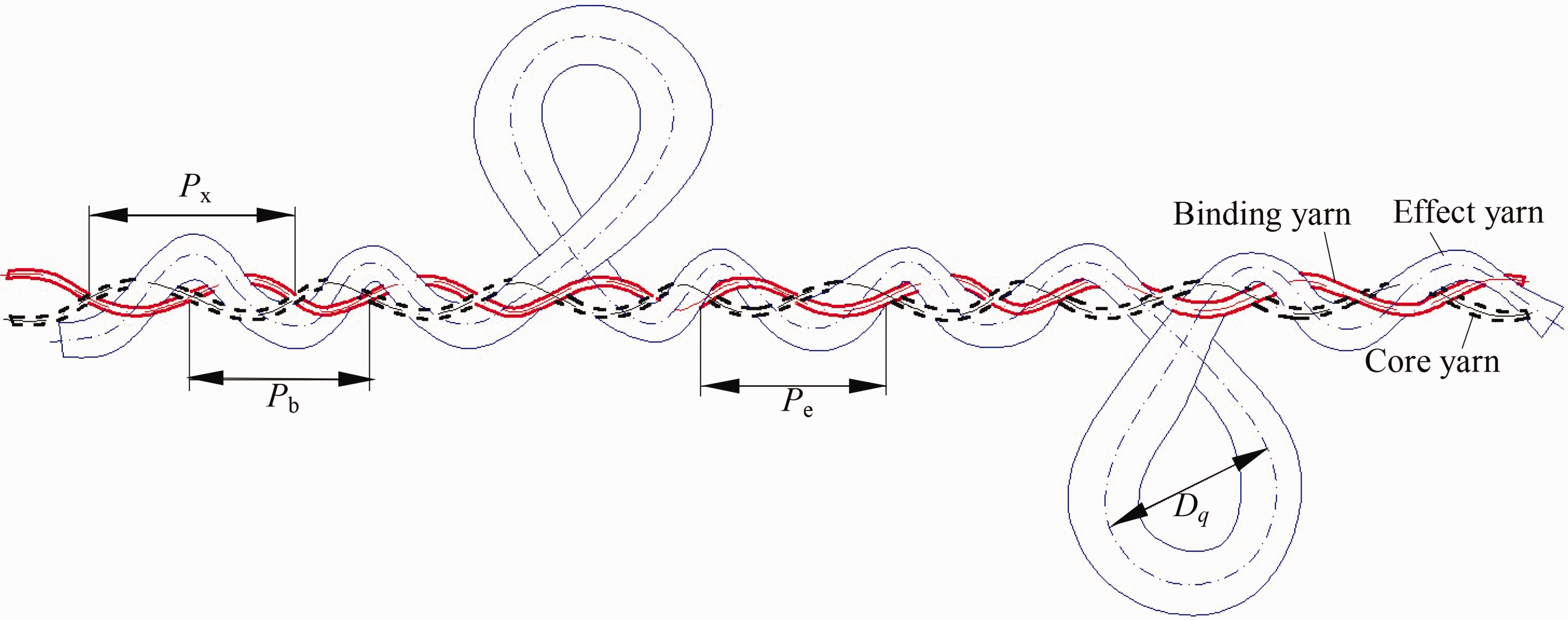
Structural diagram of loop yarn.
A schematic diagram of the loop yarn structure is shown in Figure 1. In Figure 1, the thick red solid line is the binding yarn, the thick black dashed line is the core yarn, and the thin blue solid line is the effect yarn. We use Pb, Px, and Pe to denote the pitch of the binding yarn, core yarn, and effect yarn, rb, rx, and re to denote the radius of the binding yarn, core yarn, and effect yarn, and Dq to denote the loop diameter of the effect yarn.
Calculation of component yarn length
According to Pythagoras’ theorem, 19 the opened-out axes of the component yarns are shown in Figure 2. In Figure 2, AB is the effect yarn axis of one twist le (excluding the loop length), AB′ is the effect yarn pitch of one twist Pe, AD is the binding yarn length of one twist lb, AD′ is the binding yarn pitch of one twist Pb, AC is the core yarn length of one twist lx, AC′ is the effect yarn pitch of one twist Px, β is the helix angle of the effect yarn, γ is the helix angle of the binding yarn, and α is the helix angle of the core yarn.
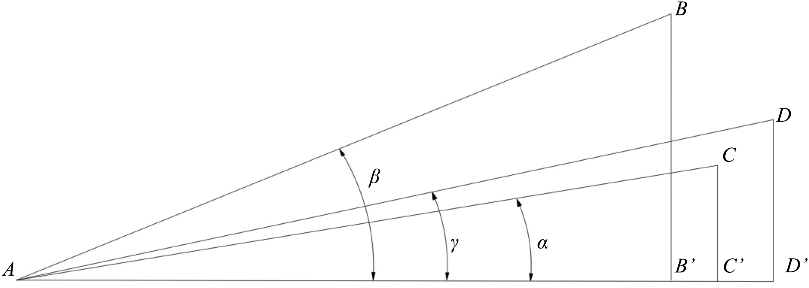
Opened-out diagram of component yarn axes.
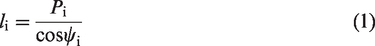
The component yarn length of one twist li is calculated as follows:
The effect yarn consists of several loops and spiral segments.
20
The loop of the effect yarn can be approximated as a circle, and a loop circumference of the effect yarn is πDq. The component yarn length per unit loop yarn is given as follows:


The binding yarn wraps around the core yarn and effect yarn, and the twist number of the loop yarn depends on the binding yarn twist. Based on the ideal structure of a loop yarn, the twist number of the binding yarn, core yarn, and effect yarn per unit loop yarn should be equal. That is, ne = nb = nx.
Calculation of the contact area between the component yarn and abrasive
Calculation of contact force between the component yarn and abrasive
According to the loop yarn model in Figure 1, when wound around an arc-shaped abrasive, the effect yarn, binding yarn, and core yarn of the loop yarn, all come into contact with the abrasive, as shown in Figure 3.
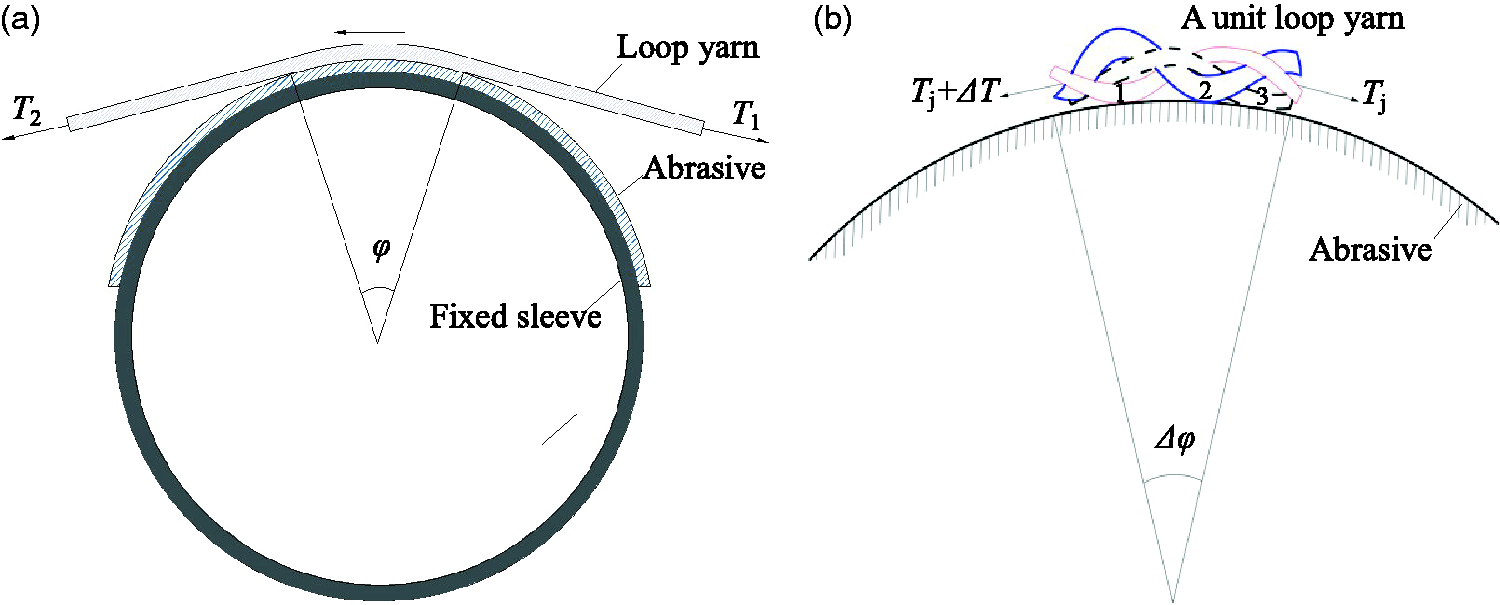
Contact between loop yarn and abrasive: (a) forces acting on the loop yarn and (b) forces acting on the loop yarn element.
In Figure 3(a), the loop yarn slides over the fixed sleeve and rubs against the abrasive. The contact length between the loop yarn and the abrasive is lq, the unit number of loop yarn in contact area is ny = lq/Pi. The effect yarn and binding yarn intersects on the same side, and the core yarn comes into contact with the abrasive; they intersect on opposite sides, and the effect yarn or binding yarn comes into contact with the abrasive. A unit loop yarn is wrapped around the abrasive, the binding yarn, effect yarn, core yarn, and the abrasive have three contact tips, as shown in Figure 3(b).
Two tensions, T1 and T2, act on the two ends of the loop yarn in contact with the abrasive, with T1 at the relaxed end, T2 at the tensioned end, and T2 > T1. The arc-shaped contact area has ny units of loop yarn. The tension, Tj and Tj + ΔT, act on the end of each unit. Assuming the tension of the loop yarn gradually increases uniformly from T1 to T2, so ΔT = (T2 – T1)/ny. The Tj and Tj + ΔT exerted by the unit component yarn on the abrasive resulted in the three normal forces: Nej acting on the tip2 of effect yarn, Nrj acting on the tip1 of the binding yarn, and Nxj acting on the tip3 of the core yarn, in turn. The tips 1, 2, and 3 are relatively close in the same unit. Thus, Nej ≈ Nbj ≈ Nxj. The contact force of the unit component yarn Nij is

Deformation of the component yarn
Regarding spatial geometry, the contact between the component yarn and the curved abrasive is similar to the contact between the rope’s strand and the guide pulley or between two strands. The component yarn of the bent loop yarn will form a spatial spiral curve. The contact between component yarn and abrasive occurs between spatial spiral yarn and a large cylinder, similar to the helical interlocking of two-ply yarn.
The loop yarn is placed on an arc-shaped abrasive with a curvature radius ρ. With no tension, the component yarn cross-section can be approximately circular, with a diameter of d0ij, as shown in Figure 4(a). When there is tension, the component yarn cross-section of the non-contact segment between the component yarn and the abrasive is approximately circular, with a diameter of d1ij. Assuming the compression deformation of the component yarn in contact with the abrasive is δij, the component yarn cross-section of the contact segment between the component yarn and the abrasive is approximately elliptical, with a semimajor axis of a1ij and a semiminor axis of d0ij – 0.5δij, and 2b0ij = d0ij – δij, as shown in Figure 4(b) and (c). The contact area between the component yarn and the abrasive is also elliptical, with a semimajor axis of a1ij and a semiminor axis of b1ij, as shown in Figure 4(d).
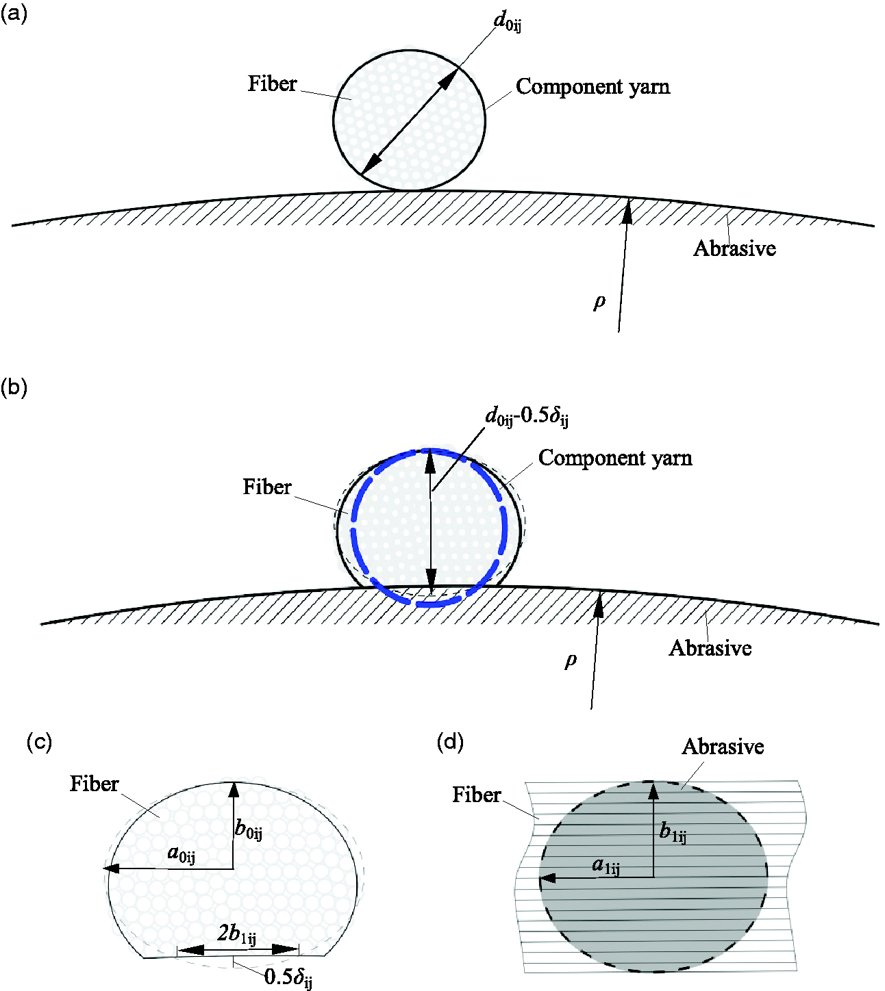
Cross-sectional morphology of component yarn in contact with abrasive: (a) when the yarn has no tension, the cross-section of the yarn is circular; (b) when the yarn has tension, the cross-section of the yarn is approximately elliptical as shown by the dashed line; (c) the cross-section of component yarn in the deformed state and (d) the contact area between component yarn and abrasive.
According to the calculation method of yarn compression,
21
the deformation under compression of the unit component yarn in contact with the abrasive is δij, which is related to the yarn pressure. The deformation δij varies versus the contact force exerted by the unit yarn,
22
relying on measurements:

For simplicity, we assume that the geometric dimension deformation of fiber assembly belongs to elastic deformation; the deformation is caused by the tension acting on the i-component yarn. The i-component yarn strain is εi, and Poisson’s ratio of the i-component yarn is vi, which is approximately the Poisson’s ratio of the component fiber. The following calculation can be obtained considering the longitudinal elongation and radial shrinkage of i-component yarn based on the constant equivalent volume of component yarn:
Here, the i-component yarn strain can be approximately calculated by the elongation of i-component yarn, and the elongation of i-component yarn is linearly related to its tensile force. Neglecting the gaps between fibers inside the i-component yarn, we assume that the deformation of the i-component yarn is synchronized with the loop yarn. According to the static theory, the strain of i-component yarn to extend the yarn can be linked to strain of loop yarn by the relationship
The helix angle of the ply yarn is related to its degree of abrasion, and the larger the helix angle, the heavier the abrasion. 15 Stretching can change the structure and size of the loop yarn and reduce the helix angle of the component yarn. After measurement, the variation range of the helix angle caused by stretching is 0–20°, and its cosine value has no significant difference. Therefore, we can ignore the influence of the helix angle. That is, Ψi0 ≈ Ψi. From Equation (8), we can obtain that εi ≈ εp.
In Figure 1, the half width of loop is rq = 0.707dq. Due to the loop distribution on the yarn’s outer side, it may not have sufficient or occasional contact with the abrasive. Estimating the contact area between the loop and the abrasive is difficult.
Calculation of contact area between the component yarn and abrasive
According to Hertz’s theory, the contact area between the component yarn and the abrasive can be approximately elliptical, 23 and the contact area is related to the force, fineness, twist, etc. From the three-component yarn wrapping around each other, it can be seen that the contact between the binding yarn, effect yarn, core yarn, and the abrasive are similar, and they have contact with the abrasive in sequence. Therefore, the contact between the three-component yarn and abrasive can be used in same calculation method.
Based on the mechanism of contact load between strands, Grishanov et al.
24
proposed the geometric shape of the contact area between two strands, and they derived the calculation formulas for the contact area’s long semiaxis a and short semiaxis b. According to Grishanov et al.’s calculation formula, the contact area’s long semiaxis aij and short semiaxis bij between the i-component yarn and the abrasive are as follows:

Contact index between fibers of the component yarn and abrasive
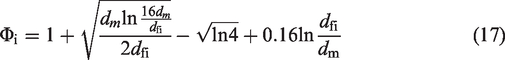
We assume that many abrasive particles with uniform size are densely distributed on the abrasive surface. The contact between fibers and abrasives conforms to the Hertz contact condition between elastic and rigid bodies. Based on the calculation equations of contact mechanics, an ideal contact mechanics model of fibers and abrasives is constructed.
Contact points
The abrasive particles have similar sizes but irregular shapes. To simplify the calculation, we assume that the abrasive particles are a regular spherical and ordered arrangement on the abrasive substrate.
The contact model of the fiber and the abrasive is shown in Figure 5. In Figure 5(a), a fiber is placed on a regular abrasive. The abrasive particle diameter is dm, and the fiber diameter is dfi. Neglecting the gaps between abrasive particles and the gaps between fibers, assuming that fibers are arranged on the abrasive in the optimal idealized state, the relationship between fibers and abrasive particles is shown in Figure 5(b) and (c).
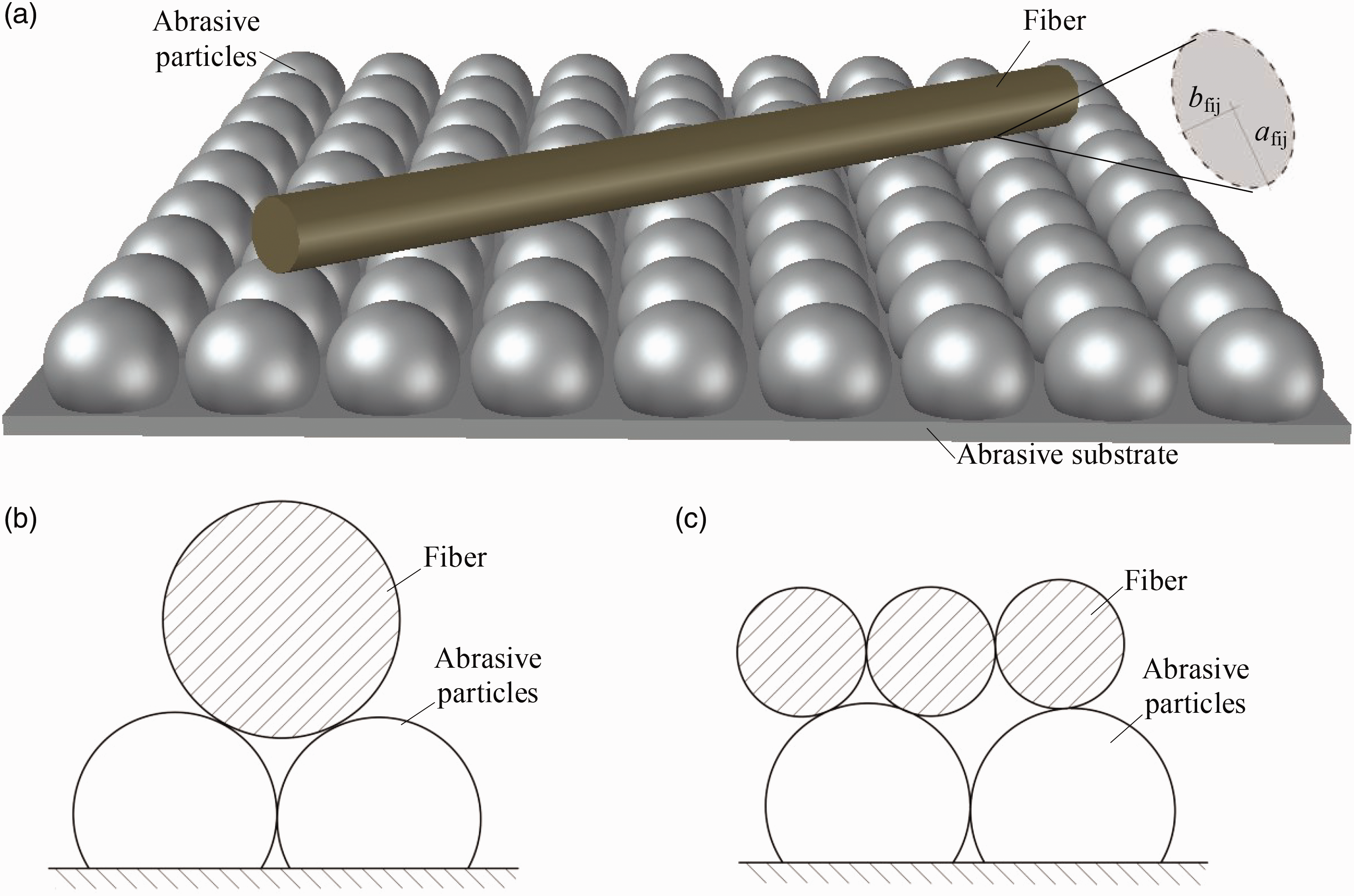
(a) Contact between a fiber of component yarn and the spherical abrasive particles. (b, c) Contact between the fiber and the abrasive particles: (b) dm < dfi and (c) dm > dfi.
When dm < dfi, a fiber is located between two abrasive particles, and their contact number g = 2. When dm > dfi, a fiber can only come into contact with one abrasive particle, g = 1. The fiber number between the unit component yarn and abrasive is as follows:
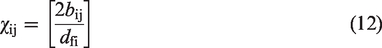
The contact number between the unit component yarn and abrasive is as follows:
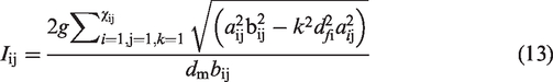
In the contact area, the contact number of the component yarn and the abrasive is Ii = ƩIij, the contact number of loop yarn and abrasive is I = ƩIi. We assume that the normal force of any component fiber in contact with the abrasive particles is all equal. That is, Nfij = Nij/Iij.
Contact area
The contact area between the component fiber and the abrasive particle can be approximately elliptica.
25
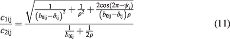
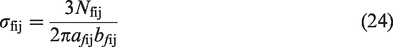
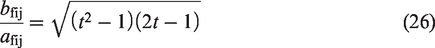
The curvature radius of the contact area between fiber and abrasive particle is Rm, and the elliptical contact area’s long and short axis radius is afij and bfij, respectively. The calculation formula
26
is as follows:
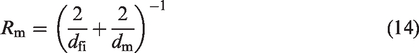
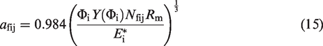
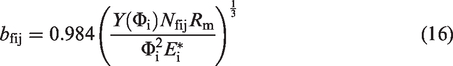

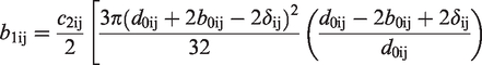
Substituting (5) into (15) and (16), we obtain
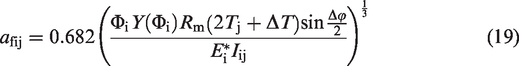
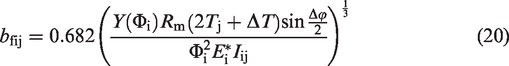
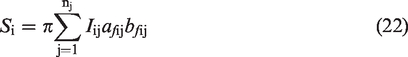
The contact area between a fiber and one abrasive particle is as follows:

The contact area between the component yarns, the loop yarn, and the abrasives can be obtained as follows:
The maximum contact stress between fiber and abrasive particle σfij is as follows:
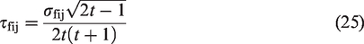
The maximum dynamic shear stress of fiber and abrasive particle τfij is as follows:
Experiments
Materials and instrument
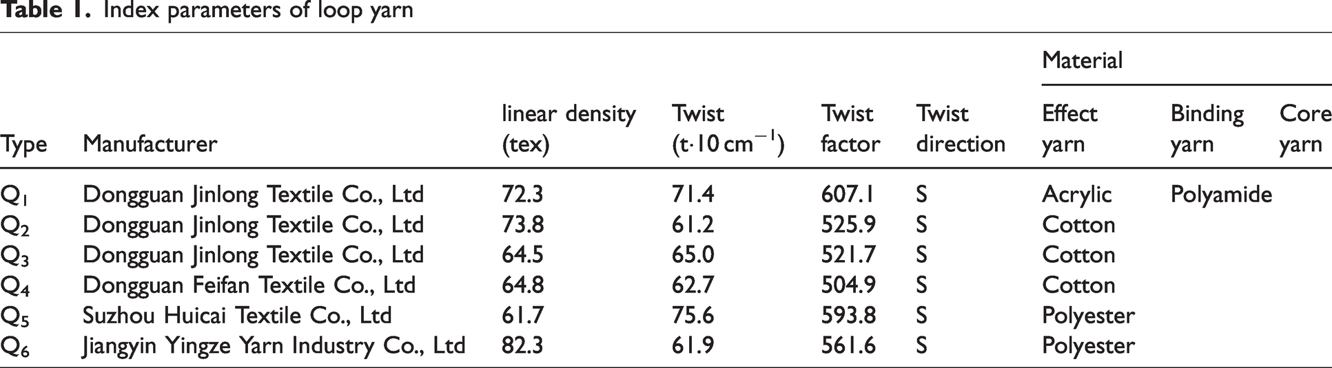
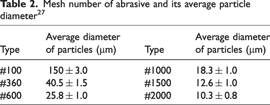
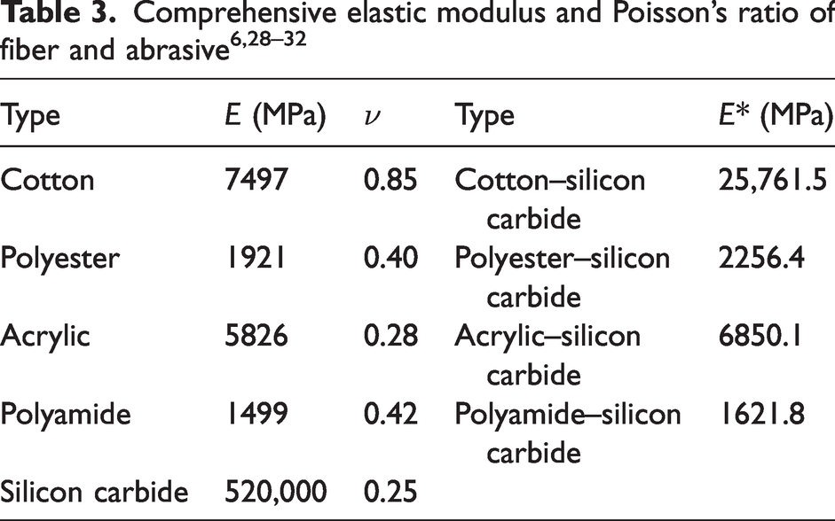
The abrasion yarn investigated in this article is loop yarn. The main properties related to the loop yarn and their component yarns are noted in Table 1. This experiment selected #100, #360, #600, #1000, #1500, and #2000 grade SiC sandpapers from China as the abrasives. According to ISO 6344: 1998, the average particle diameter of abrasive is given in Table 2. 27 The comprehensive elastic modulus and Poisson’s ratio of fiber and abrasives are noted in Table 3.
Index parameters of loop yarn
Mesh number of abrasive and its average particle diameter 27
The linear density of the yarn was determined by the hank method on a yarn-measuring length instrument. The twist of the loop yarn was determined on a Y331A yarn twist tester. The fiber diameter was determined on a BC4K-3630 digital microscope. The yarn diameter was determined on a BC4K-3630 digital microscope.
A yarn friction tester was built to obtain the worn yarn, generally used for abrading yarn on sandpaper. An XM3-103 high-speed camera system was set up above the yarn friction apparatus and used to capture the images of the yarn sliding over the abrasive.
Friction test of loop yarn
In the experiment apparatus (Figure 6), two 24 V DC deceleration motors with a speed of 296 revs/min were used as the driving motors for the traction wheel and delivery wheel, and their linear velocity was 0.622 m/s. The diameter of the abrasion sleeve was 105 mm, and the contact length of the yarn and the abrasive was 75 mm.
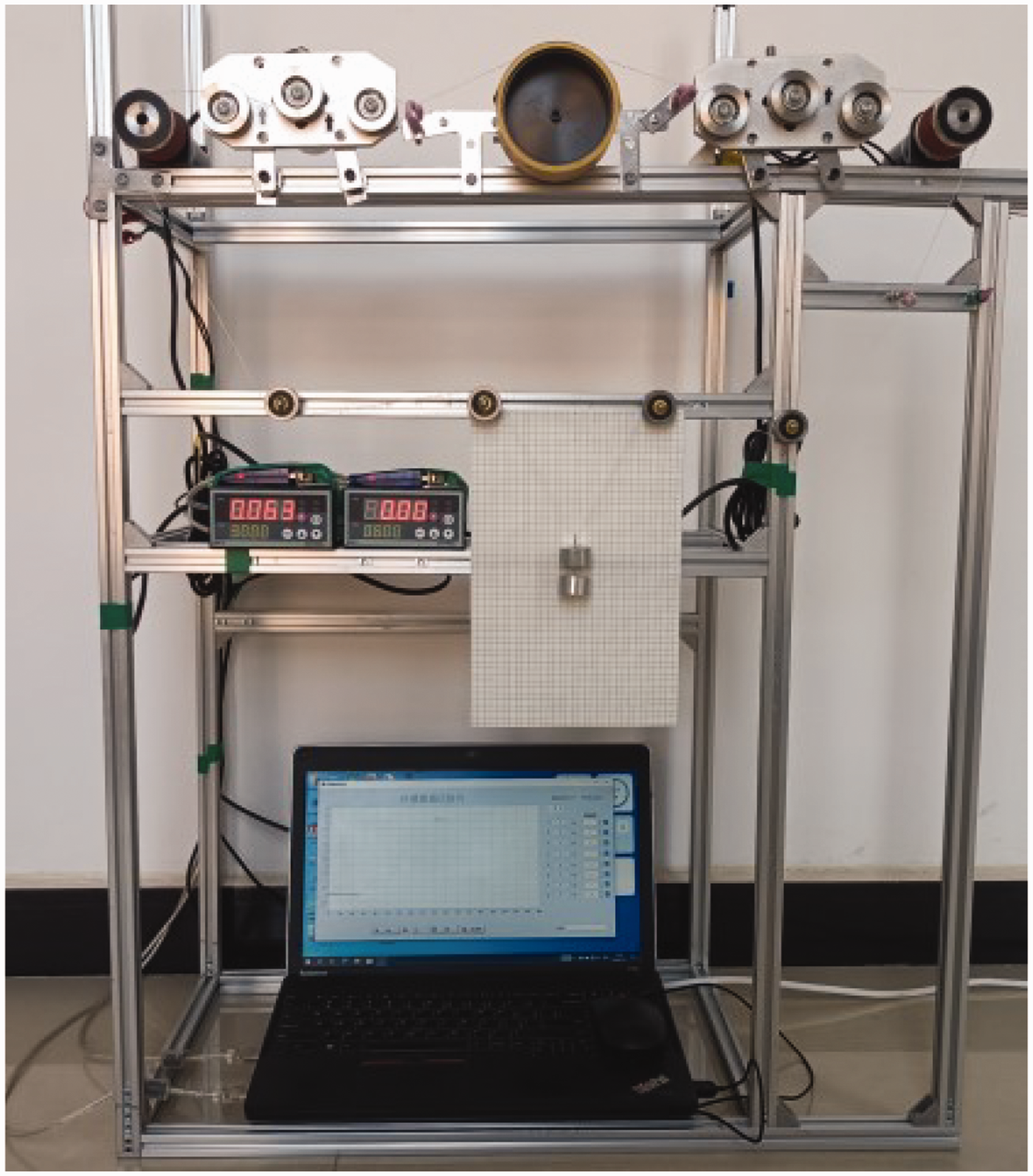
Yarn friction apparatus.
Sandpaper grades #100, #360, #600, #1000, #1500, and #2000 were selected as the abrasive for yarn friction testing; the pretension of the yarn was 2N(200g) weight). For friction testing, the loop yarn was installed in the yarn-to-abrasive apparatus, and the tension sensor recorded the tensile force value from the loop yarn applied to the tension wheel during the friction process. The loop yarn was subjected to friction testing on the yarn friction apparatus, and two tension sensors collected the normal force value of the loop yarn at both ends of the friction area, which was the contact area of the loop yarn and abrasive.
According to the positional relationship between the tension wheel and the yarn guide wheel of the tension sensor, the normal force can be converted into tension of the loop yarn using the following formula
33
:
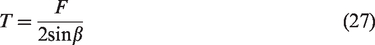
When the loop yarn slides over the abrasive, its frictional force Ff is taken as the difference between the tension T1 and T2. That is, Ff = T2 – T1. The frictional coefficient μ of the loop yarn and the abrasive based on the non-Euler formula
34
can be calculated as follows:
Results and analysis
Contact index between fiber and abrasives
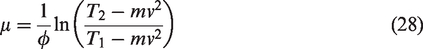
Figure 7 shows one cycle contact index of the Q1 loop yarn on the friction device (sandpaper grade #360).
Friction index, contact number, contact area, distribution force, and contact stress of the unit fiber when the Q1 loop yarn comes into contact with #360 abrasive: (a) T1 and T2; (b) Ff and μ; (c) Sfij; (d) Iij; (e) Sij; (f) Nfij; (g) σfij and (h) τfij.
In Figures 7(a) and (b), as friction progresses, T2, Ff, and μ of the Q1 loop yarn gradually decrease with some fluctuations, whereas T1 has almost no change with slight fluctuations. The abrasive particles have a hindering effect the sliding of the loop yarn; they scrape off the apparent fibers, causing them to be damaged and fall off, and can also alter the yarn structure. The friction between the loop yarn and the abrasive causes fiber detachment, with some fibers remaining between the abrasive particles. This improves the microcontact environment on the abrasive surface, leading to a decreasing trend in the abrasive’s hindrance effect.
We calculate the contact area and force between the Q1 loop yarn unit and the abrasive using the max, min, and mean values of T2 and T1 in Figure 7(a). The contact area and force between the Q1 loop yarn unit and the abrasive particles from contact to separation are shown in Figures 7(c)–(h).
As can be found through Figures 7(c)–(e), by increasing lq or j, Tj will increase, Sfij, Iij, and Sij of each unit in contact with the abrasive will also increase, and the fluctuation range of their values will also enlarge. The greater the tension of the loop yarn, the larger the contact number and area. Among them, Sfij and Sij are Q1b ≈ Q1x > Q1e; Iij is Q1e > Q1x ≈ Q1b. The effect yarn with thin fiber has more fibers than other component yarns, and its single-fiber contact area with the abrasive is small. In contrast, the contact number between the unit and the abrasive is greater than that of other component yarns.
In Figures 7(f)–(h), as lq or j increase, Nfij, σfij, and τfij of each unit in contact with the abrasive all increase, and the fluctuation range of their values increases. The greater the tension of the loop yarn, the larger the contact force and stress. However, the fluctuation range of Nfij is relatively more significant than the fluctuation ranges of σfij and τfij. The tension on the contact force of the loop yarn unit fiber has a much more significant influence than its maximum contact stress and dynamic shear stress. Among them, Nfij is Q1b ≈ Q1x > Q1e, σfij and τfij are Q1e > Q1b ≈ Q1x. At the separation point between the loop yarn and the abrasive (lq = 75 mm, j = ny), Nfij, σfij, and τfij of the last unit reach a maximum.
Contact number and the area between loop yarn and abrasives
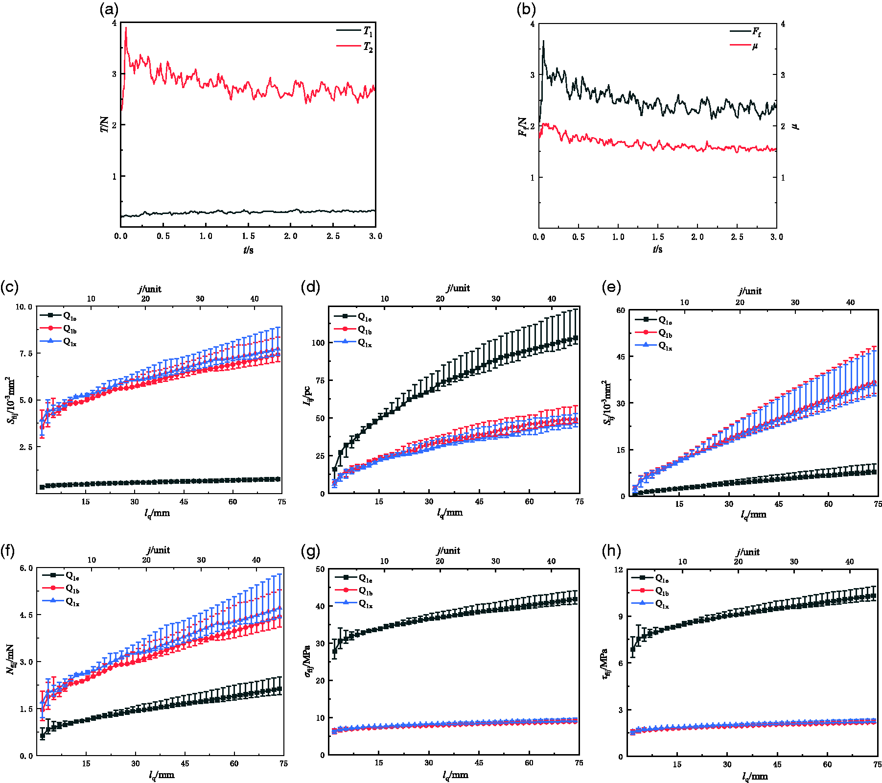
The frictional indexes of the Q1-Q6 loop yarn contact with different abrasives are shown in Figure 8.
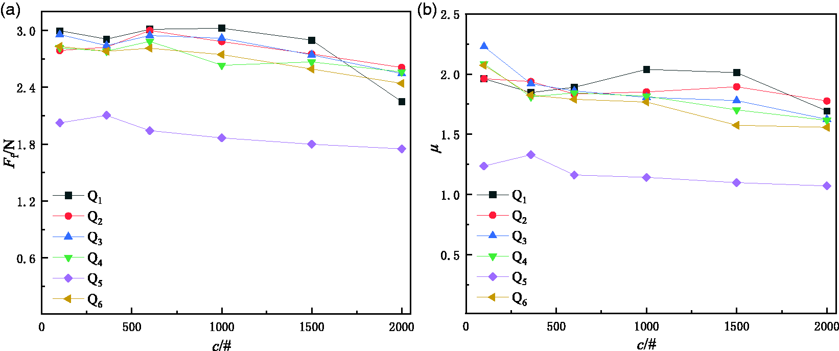
Friction index between loop yarn and abrasives: (a) Ff and (b) μ.
In Figure 8, the Ff and μ of Q5 loop yarn are much lower than those of other types of loop yarn, while the Ff and μ of other types of loop yarn have no significant difference. As the particle mesh of the abrasive increases, the Ff and μ between the loop yarn and the abrasive generally decrease approximately. This indicates that the tension carried for the loop yarn unit and the force applied to the abrasive gradually decrease as the mesh.
The contact morphology between the loop yarn and the abrasive is very complicated, and the ideal contact model of the two can approximately express their contact number and area. The calculation formulas for the contact number and area are relatively complex, making it challenging to obtain the variation law of contact indexes between loop yarn and abrasives of different particle meshes from the formulas. Based on the idealized contact morphology between fibers, yarns, and abrasives, we use Equation (13) to calculate the contact number between a unit’s component yarns and abrasives, as shown in Figure 9; according to the calculation methods of Equations (22) and (23), the contact area between the component yarn, the loop yarn and the abrasive are shown in Figure 10.
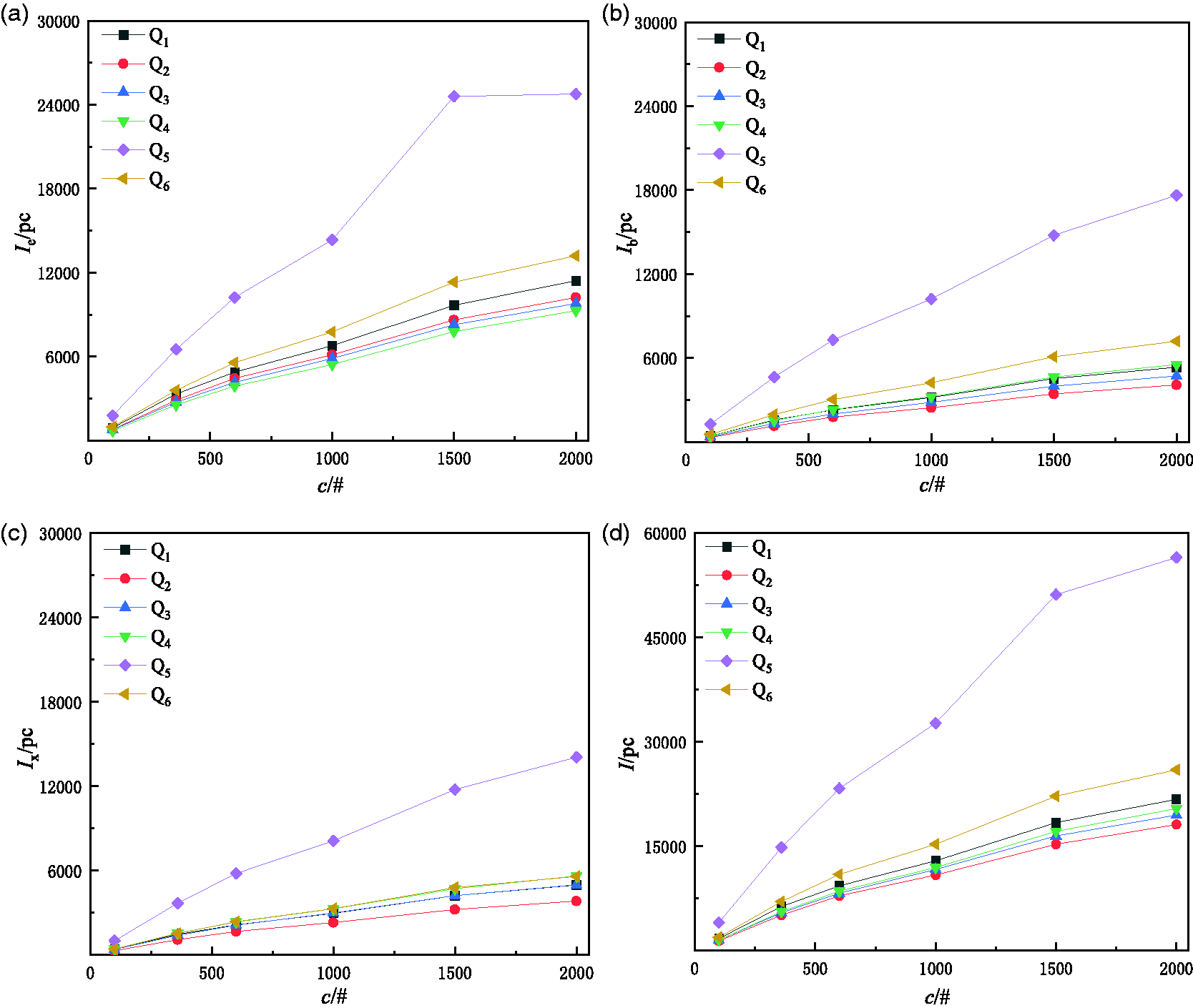
Contact number between the loop yarn and the abrasive: (a) Iej; (b) Ie; (c) Ibj; (d) Ib; (c) Ixj; (c) Ix and (d) I.
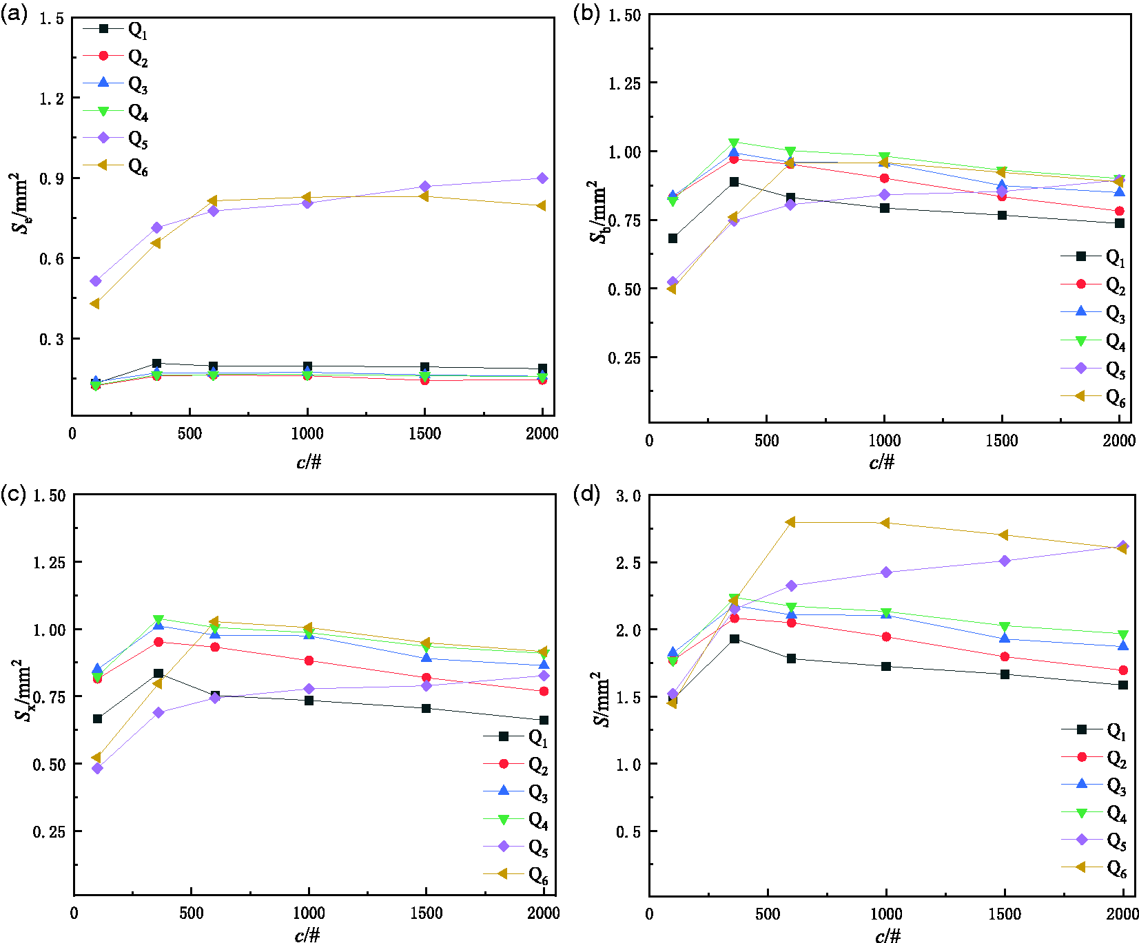
Contact area between the component yarn, loop yarn and the abrasive: (a) Se, does not contain loops of effect yarn; (b) Sb; (c) Sx and (d) S.
In Figure 9, the contact number between the component and loop yarn with the abrasive gradually increases with the abrasiveness of the mesh. The contact number between the effect yarn and the abrasive particles is greater than between the other component yarn and the abrasive. We compare the contact numbers of different types of loop yarn and find that Ie is Q5 > Q6 > Q1 > Q2 > Q3 > Q4, Ib is Q5 > Q6 > Q4 >Q1 > Q3 > Q2, Ix is Q5 > Q6≈Q4 > Q3≈Q1 > Q2, and I is Q5 > Q6 > Q1 > Q4 > Q3 > Q2. It can be seen that the contact numbers of Q5 are much larger than those of other types of loop yarn. The fibers of Q5 are finer than others and consist of multiple fibers. The contact numbers between the binding yarn, core yarn, and abrasive are similar and related to the same fiber material: nylon fiber. Twisted nylon yarn is commonly used for binding yarn, while twistless nylon yarn is widely used for core yarn. The contact number between the component yarn and the abrasive is related to the fiber and yarn diameter. Under the same contact conditions, the finer the fiber diameter, the thicker the yarn diameter, the more fibers there are in the yarn, and the more contact number between the component yarn and the abrasive.
In Figure 10, the contact area between the component yarn, loop yarn and the abrasive increases first and then decreases as the abrasive mesh. When the abrasiveness of the mesh is #600 or higher, the abrasive particle size is close to the fiber diameter, and the contact area of the component yarn slightly decreases. We find that Sb ≈ Sx > Se by comparing the contact area between the component yarn and the abrasive. The contact area of the effect yarn is Q5 ≈ Q6 > Q1 > Q2 ≈Q3 ≈ Q4. The contact area between the binding yarn and the abrasive is not significantly different between the core yarn and the abrasive. If the structural difference of the component yarn is ignored, the contact area is nylon > polyester > acrylic > cotton by material type.
The effect yarns of Q2–Q4 loop yarns are all cotton fibers, and their contact area with abrasives is almost equal. The effect yarns of Q5 and Q6 loop yarn are made of polyester, and there is no significant difference in the contact area between them and abrasives. The binding and core yarn of loop yarn are made of nylon, and there is no significant difference in their contact area with the abrasive. The contact areas of the component yarns, which are made of the same material, are not significantly different. The fiber diameter and elastic modulus significantly affect the contact area. The smaller the fiber diameter, the lower the elastic modulus, and the higher the contact area.
Contact force and ratio coefficient
By Equations (24)–(26), the Nij-max, σij-max, and τij-max (lq = 75 mm, j = ny) obtained are shown in Figure 11.
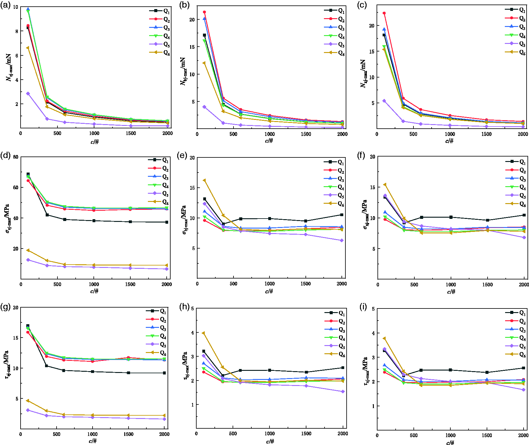
Contact force and stress between the Q1–Q6 fibers and the abrasives: (a) Nej-max; (b) Nbj-max; (c) Nxj-max; (d) σej-max; (e) σbj-max; (f) σxj-max; (g) τej-max; (h) τbj-max and (i) τxj-max.
In Figure 11, as the abrasive mesh increases, Nij-max, σij-max, and τij-max continuously decrease. Under the same conditions, Nbj-max ≈ Nxj-max > Nej-max, Nij-max of Q5 component fiber is the smallest, σej-max and τej-max of fiber of Q5 effect yarn are also the smallest, σij-max and τij-max of each component fiber are also close. By comparing the contact force and stress, we find that they can be arranged by fiber material for cotton, acrylic, polyester, and nylon, in descending order.
Cornelissen et al.
35
proposed that the contact area Sfij between a fiber and an abrasive particle has the following nonlinear relation with the fiber contact force 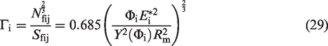
According to Equation (29), Гi ≈
Discussion
Relationship between contact index and friction index
From Figures 8 and 9, the contact number and friction index trends are opposite, and their curves can both be approximated as straight lines. As the abrasive mesh increases, the contact area curve between the loop yarn and the abrasive follows an approximate parabola, entirely different from the contact number curve. For abrasiveness above #360 mesh, the contact area between the loop yarn (except Q5) and the abrasive continuously decreases, and this trend is consistent with that of the friction index.
The smaller the abrasive particle size, the lower the hinder force of the abrasive on the loop yarn, and the higher the contact number, whereas the contact area also tends to decrease. This indicates that the friction between the loop yarn and the abrasive is not solely determined by load but is also related to other factors such as fiber diameter, abrasive diameter, fiber modulus, and particle shape. The higher the abrasive diameter, the more significant the size effect of irregular abrasive, and the higher the probability of the irregular protrusions scraping fibers. It is not simply a frictional contact but should include other unpredictable scraping effects.
Kaliski 36 found that the smaller the particle size and the more particles on the material surface in contact with fibers, the lower the frictional force. Except for the asperity number and the asperity radius, the other conditions were the same. He proposed an empirical function that multiplied the square root of the asperity number by the asperity radius, and the frictional coefficient was equal to a dimensionless coefficient δ.
According to Kaliski’s empirical formula, multiplying the square root of contact number by abrasive particle radius and frictional force is δf = 0.5 ×10⁻³I0.5dmFf, and multiplying the square root of contact number by abrasive particle radius and frictional coefficient is δμ= 0.5 × 10⁻³I0.5dmμ. Their relationship with abrasive mesh is shown in Figure 12.

(a) Effect of abrasive mesh on δf and (b) effect of abrasive mesh on δμ.
In Figure 12, both δf and δμ decrease with the abrasiveness of the mesh, and their curves are approximately concave shape. However, δf and δμ of the Q1–Q6 loop yarn are not significantly different. We calculated the mean values of Ff and μ of the same mesh separately, then by fitting for obtaining δf = 115.720c−0.538, δμ = 61.982c−0.515. These can be used as an approximate calculation method for the friction index of loop yarn.
El Mogahzy and Gupta4,37 derived a fiber contact model and found that the contact number between fibers in line contact was higher than in point contact. There are fewer asperity particles on the surface of rough fibers than on smooth fibers, and the frictional coefficient is lower when the fiber surface is highly smooth. This trend is consistent with the principle of friction and our conclusion. El Mogahzy and Gupta analyzed the relationship between the asperity number on the fiber surface and friction at the microscale. The asperity size on the material surface analyzed is smaller than the contact size between the abrasive and the fiber discussed in this article.
Structural and contact model
The geometrical model of multi-ply yarn covers several types of fancy yarns, such as bouclé, gimp, wavy, and loop yarn. The loop yarns we tested are all composed of three component yarns, and their structures are similar. This model can be extended to account for multi-ply fancy yarns made with two- or three-effect yarns. The structural model of the loop yarn mathematically followed a method suitable for multi-ply fancy yarns.
Real contact area could not be measured directly. Some studies mainly focused on the contact analysis of fiber tows under hypothetical or idealized conditions. The Hertz contact model can be applied to accurately explain the normal contact (without adhesion) between elastic bodies. The Maugis–Dugdale adhesive contact model provides insights into the adhesion contact area. The JKR contact model, which is based on Hertz contact model, was proposed for the contact application with adhesive. Cornelissen et al. 9 proposed that the results of the Hertz contact and Maugis–Dugdale adhesive contact model had little difference under the same pressure. Che et al. 10 also believed the fiber contact tips were elastic with little adhesion in the sliding process: the contact area under JKR model is approximately equal to that under Hertz model. To analyze the frictional behavior of different types of yarn, we use the contact index to evaluate the contact difference.
The contact model mentioned in this paper can be applied to analyze the contact behavior between any multi-ply fancy yarn and abrasive. To simplify the calculation, the contact form between cylindrical fibers and spherical abrasive particles has been discussed at the microscopic level, ignoring the actual particle distribution on the abrasive and the fibers’ surface morphology characteristics. Subsequent research will obtain the apparent morphology of abrasives using 3D scanners, and statistical methods will also be used to analyze the abrasives’ distribution characteristics, further optimizing the simulation calculation data.
Conclusion
Loop yarn sliding over an abrasive is a typical sliding friction phenomenon. Based on the structural characteristics of the loop yarn, we have assumed that the contact between fibers and abrasives is a typical Hertz model and have derived the calculation formulas for the loop yarn’s contact number, area, and force. The calculation results indicate that as the tensile force of loop yarn increases, the contact number, area, and force of fiber also increase. Under the same contact conditions, the thicker the diameter of the component yarn, the finer the fibers, and the more contact pits between the loop yarn and abrasives. The contact area does not continuously increase with the increase of abrasive mesh, while the contact force and stress are opposite; they are related to the physical indexes of the fibers and component yarns. The ratio of the force applied by the loop yarn on the abrasive to their contact area is related to the material and size of the yarn, which can provide feedback on the wear resistance of the yarn. Multiplying the square root of the contact number of the loop yarn by the radius of the abrasive particles and the frictional forces or coefficient are all dimensionless coefficients, and these coefficients are similar for different types of loop yarn in contact with abrasives of the same mesh, which can be used as a feedback index for friction performance.
Footnotes
Declaration of conflicting interests
The author(s) declared no potential conflicts of interest with respect to the research, authorship, and/or publication of this article.
Funding
The author(s) disclosed receipt of the following financial support for the research, authorship, and/or publication of this article: This work was supported by the Bintuan Science &Technology Program (grant numbers 2023CB009-06 and 2024DA037).