
Abstract
With the advancement of manufacturing toward intelligence and digitalization, automation technologies have become integral across various industries. However, the nonwoven fabric industry continues to face challenges such as high labor costs and low automation levels, creating an urgent need for technological innovation to enhance production efficiency and product quality. This study introduces an intelligent ferrous metal detection and removal automation system, designed specifically for industrial deployment in nonwoven fabric production lines. It integrates an optimized coil arrangement, an edge-aware adaptive cutting optimization algorithm, and a pneumatic–hydraulic driven removal device, ensuring high detection precision, minimal material waste, and seamless integration into continuous production workflows. The system employs a triangular coil arrangement to optimize magnetic field distribution, significantly improving detection sensitivity and accuracy. The edge-aware adaptive cutting algorithm precisely locates ferrous metal impurities while minimizing damage to material edges, thereby preventing twisting or deformation of the fabric during transport that could lead to machine jamming. In addition, a pneumatic–hydraulic driven removal device is designed to efficiently excise impurity areas with high precision. Experimental results demonstrate the system’s capability to detect and remove iron particles as small as 1.2 mm in diameter, substantially improving automation levels and production efficiency in nonwoven fabric manufacturing.
Against the backdrop of the accelerated transformation of global manufacturing toward intelligence and digitization, Industry 4.0, as the core of the new industrial revolution, emphasizes the deep integration of information technology and manufacturing technology. It has become a key strategy to enhance the competitiveness of the manufacturing sector.1–3 The nonwoven industry, closely related to various sectors such as environmental protection, healthcare, filtration, and automotive, plays an important role in public health, disease prevention, environmental protection, and energy conservation. Nonwoven fabrics, with their excellent properties such as lightweight, breathability, water resistance, and antibacterial capabilities, are widely used in fields such as healthcare, automotive interiors, and environmental filtration.4–9 However, the industry still faces challenges such as high labor costs, low automation levels, and low production efficiency, urgently requiring technological innovation to improve production efficiency and market competitiveness.10–12
The realization of continuous, automated, and intelligent production processes has become an inevitable trend in the textile manufacturing industry. This not only helps improve production efficiency and reduce operational costs, but also ensures product quality, meeting the high standards of efficiency, flexibility, and intelligence demanded by modern industries.
Wood pulp rolls, as an important raw material in the nonwoven production, may contain metal impurities (primarily iron-based contaminants) that could damage production equipment, leading to safety hazards and product quality issues.13,14 Due to their thickness, which is much greater than that of ordinary nonwoven fabrics, and their opacity, traditional visual inspection methods struggle to effectively detect and remove metal impurities.15–18 Moreover, existing metal detection technologies, although available in some industries, have seen limited real-world deployment in nonwoven fabric production due to their inability to meet the precision and reliability requirements of industrial-scale manufacturing. Many algorithms that perform well in laboratory settings fail to maintain the same level of accuracy and efficiency on high-speed production lines, where factors such as material movement, environmental noise, and real-time processing demands create additional challenges. Therefore, developing an automated device with high sensitivity that can accurately detect and automatically remove metal impurities is of significant practical importance.
Currently, metal detection technologies mainly include methods such as electromagnetic induction, ultrasonic testing, and X-ray inspection. Among these, electromagnetic induction is widely used in production lines due to its low cost and ease of operation, but it suffers from issues of low sensitivity and the inability to accurately locate metal impurities in thick materials.19–21 Although X-ray inspection offers good penetration capabilities for thick materials, it comes with high equipment costs and radiation risks.22–24 Ultrasonic testing has advantages in detecting metal defects, but its application is limited in nonmetallic materials.25,26
To address the aforementioned issues, this paper proposes an intelligent metal detection and removal automation system, integrating an optimized coil arrangement, an edge-aware adaptive cutting optimization algorithm, and a high-precision, pneumatic–hydraulic driven removal device. The system utilizes the principles of eddy current sensors and self-excited oscillation detection circuits to optimize the arrangement of detection coils, improving the speed and sensitivity of metal detection in thick wood pulp rolls. Through adjustable sensitivity settings and LED indicators, it enables the preliminary localization of metal impurities. The device can move freely along the XY axis, performing multidirectional secondary inspections of the wood pulp rolls. It analyzes the signal peaks from the detection coils to achieve precise localization of metal impurities. In terms of metal impurity removal, a removal device driven by a pneumatic–hydraulic booster cylinder and a cutting knife is designed. When metal impurities are detected, the edge-aware adaptive cutting optimization algorithm first identifies the cutting position. This algorithm optimizes the center and radius of the cutting circle by accurately determining the position of the metal impurity, ensuring that the cutting area does not approach the material edge. This helps avoid issues such as twisting, deformation, or even equipment jams due to uneven force during material transport. Once the position is confirmed, the pneumatic–hydraulic booster cylinder drives the circular cutter to remove the area containing metal from the wood pulp roll. The cut portion is then trapped in the circular cutter slot. The device then moves the pneumatic–hydraulic booster cylinder to the collection area, using a small internal cylinder within the circular cutter to push the cut portion out of the slot and into the collection area. This process ensures the effective removal of metal impurities, preventing equipment damage and production safety risks. To ensure complete removal of metal impurities, the removal device returns to its origin after cutting, and the detection system starts to move longitudinally, reinspecting the previously processed areas to confirm that no residual impurities are present, thus preventing any effect on subsequent production. Meanwhile, to maintain production continuity, a backup wood pulp roll operates in parallel, monitored by another set of metal detection and removal devices, ensuring the efficient operation of the production line.
The intelligent metal detection and removal automation system proposed in this paper not only solves the problem of metal impurity detection in thick wood pulp rolls but also achieves efficient impurity removal and continuous, high-efficiency production line operation through innovative removal devices and optimization algorithms. This has significant implications for improving the automation level and market competitiveness of the medical nonwoven fabric industry.
Working principle
The working principle of an eddy current sensor is based on the eddy current effect, as illustrated in Figure 1. When an alternating current I1 flows through a coil, an alternating magnetic field H1 is generated around the coil. When a metal conductor enters this alternating magnetic field, either approaching or moving away from the coil, the magnetic flux Φ1 within the coil changes. According to Faraday’s law of electromagnetic induction, a change in the magnetic field induces eddy currents I2 in the closed conductor. The variation in the eddy currents creates a new magnetic field H2, which, according to Lenz’s law, opposes the direction of H1, partially weakening the strength of H1. This leads to a change in the sensor’s impedance, inductance, and quality factor.
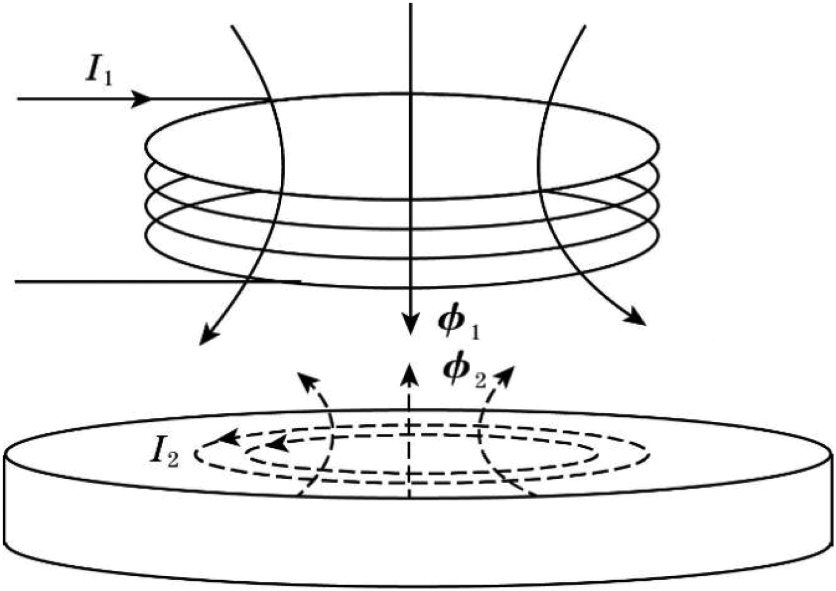
Schematic diagram of the eddy current effect.
The magnitude of the eddy currents is related to the thickness of the metal conductor, the material, the frequency of the coil’s excitation current, and the distance from the surface of the metal conductor. 10
Coil design
Coil arrangement method
The arrangement of the coils is shown in Figure 2. The detection coils are arranged in two rows, with every three coils connected in series to form a small detection area. These coils are arranged in a triangular pattern, and they output a single detection signal.
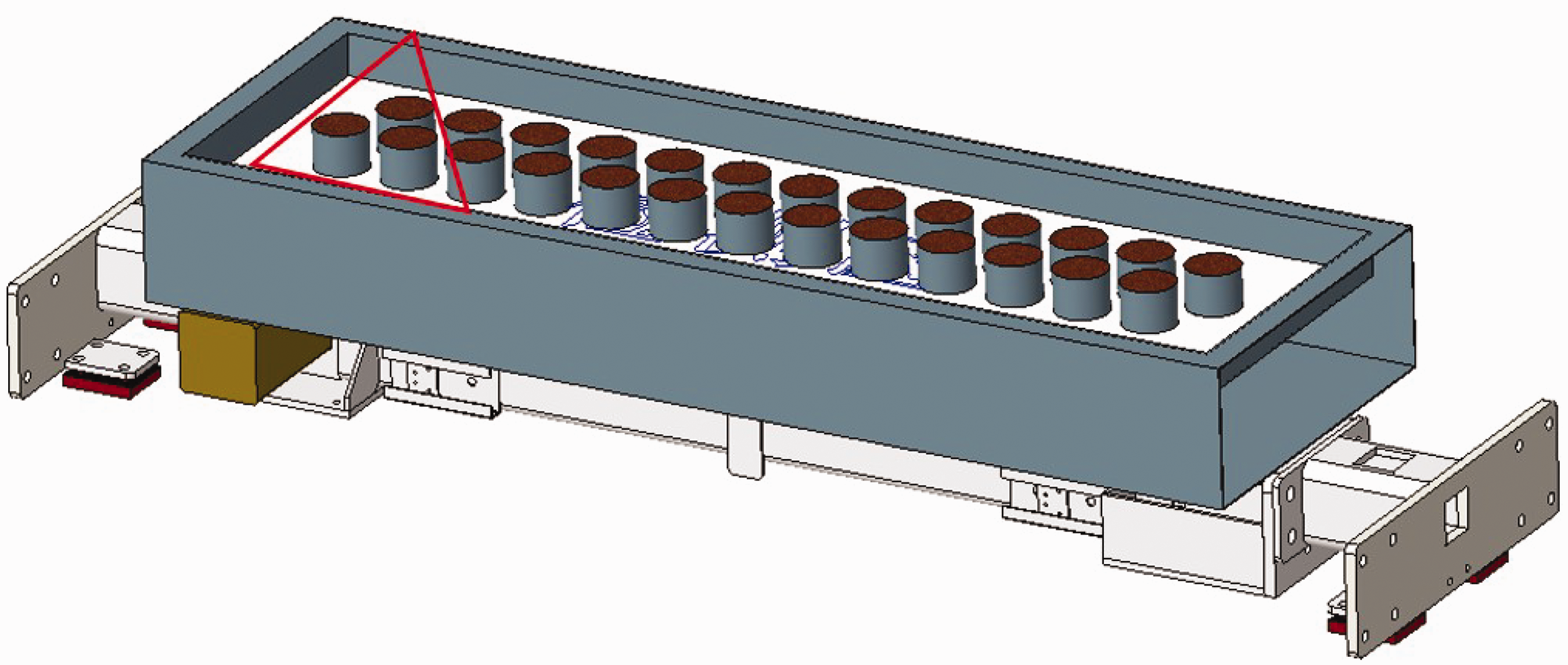
Coil arrangement method.
This arrangement effectively reduces electromagnetic interference between adjacent small detection areas, thereby improving the accuracy and reliability of detection. The triangular arrangement provides a more uniform magnetic field distribution compared with the traditional linear arrangement, helping to minimize detection blind spots and enhance overall detection efficiency. In addition, the triangular layout makes better use of space, especially when deploying multiple detection coils in a confined area.
Simulation study of coil structural parameters
The shape and size of the probe coil significantly affect the stability and sensitivity of the eddy current sensor. To achieve better metal detection sensitivity, simulations are conducted sequentially on the inner and outer diameters of the probe coil. The static magnetic field analysis of the three series-connected coils is performed using ANSYS Workbench, with the following simulation parameters: frequency, 25 kHz; number of coil turns, 100 turns; conductive area, 5 × 10⁻⁴ m2; current through the coil, 1 A; coil thickness, 40 mm; center-to-center distance between two coils, 45 mm; core diameter, same as the inner diameter of the coil.
Simulation study of coil inner diameter
When the coil’s outer diameter is 37 mm and the inner diameters are 15, 17, and 19 mm, the results for current density, total magnetic flux density, and total magnetic field strength are obtained. The static magnetic simulation analysis is shown in Figure 3, and the average values of current density, total magnetic flux density, and total magnetic field strength are listed in Table 1.

Static magnetic simulation analysis of coils with different inner diameters: (a) current density map for inner diameter 15 mm; (b) total magnetic flux density map for inner diameter 15 mm; (c) total magnetic field strength map for inner diameter 15 mm; (d) current density map for inner diameter 17 mm; (e) total magnetic flux density map for inner diameter 17 mm; (f) total magnetic field strength map for inner diameter 17 mm; (g) current density map for inner diameter 19 mm; (h) total magnetic flux density map for inner diameter 19 mm and (i) total magnetic field strength map for inner diameter 19 mm.
Results of magnetostatic simulation analysis for different coil inner diameters
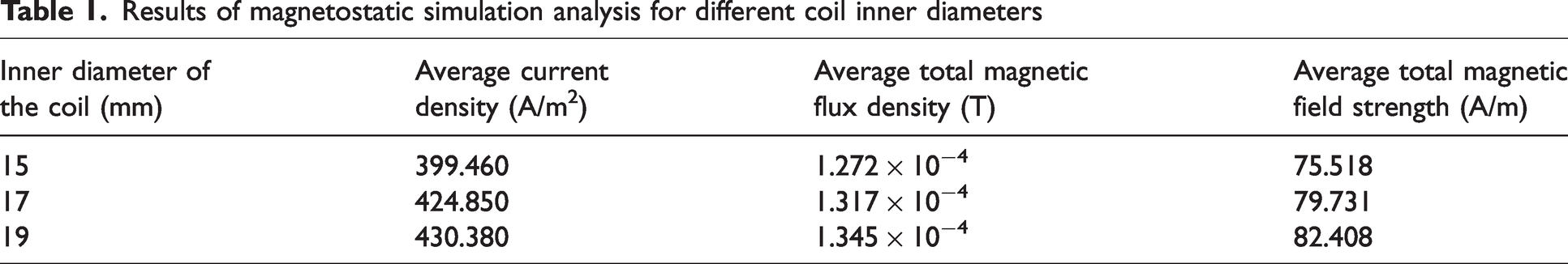
As is indicated in Table 1, when other parameters of the detection coil remain unchanged, the average values of current density, total magnetic flux density, and total magnetic field strength continuously increase as the inner diameter of the coil increases from 15 to 19 mm. Consequently, the sensitivity of the probe coil gradually improves, and the final inner diameter of the coil is determined to be 19 mm.
Simulation study of coil outer diameter
When the inner diameter of the coil is 19 mm and the outer diameters are 33, 35, and 37 mm, the results for current density, total magnetic flux density, and total magnetic field strength are obtained. The static magnetic simulation analysis is shown in Figure 4, and the average values of current density, total magnetic flux density, and total magnetic field strength are listed in Table 2.

Static magnetic simulation analysis of coils with different outer diameters: (a) current density map for outer diameter 33 mm; (b) total magnetic flux density map for outer diameter 33 mm; (c) total magnetic field strength map for outer diameter 33 mm; (d) current density map for outer diameter 35 mm; (e) total magnetic flux density map for outer diameter 35 mm; (f) total magnetic field strength map for outer diameter 35 mm; (g) current density map for outer diameter 37 mm; (h) total magnetic flux density map for outer diameter 37 mm and (i) total magnetic field strength map for outer diameter 37 mm.
Static magnetic simulation results for coils with different outer diameters
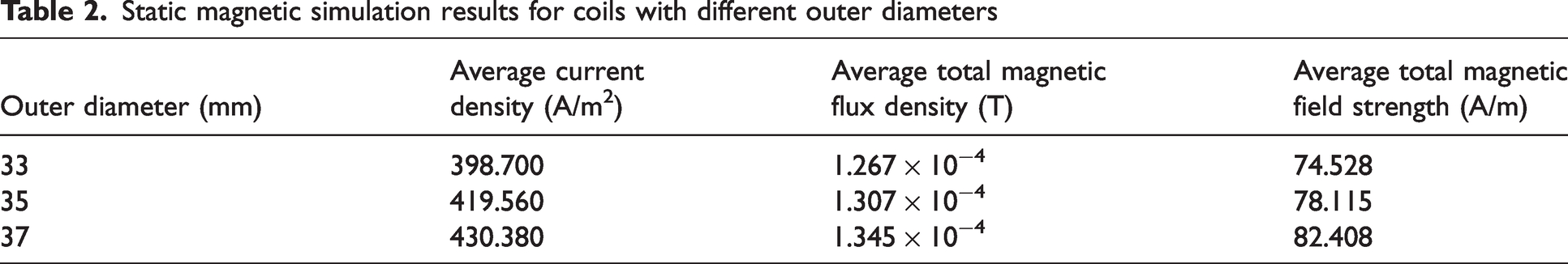
As indicated in Table 2, when other parameters of the detection coil remain unchanged, the average values of current density, total magnetic flux density, and total magnetic field strength continuously increase as the outer diameter of the coil increases from 33 to 37 mm. Consequently, the sensitivity of the probe coil gradually improves, and the final outer diameter of the coil is determined to be 37 mm.
It can be seen that both the inner and outer diameters of the coil influence the total magnetic field strength. When the number of turns of the coil remains unchanged, the inner and outer diameters of the coil increase within a certain range, and the coverage area of the coil increases, resulting in an increase in the magnetic flux Ф (Ф = B × A), thereby inducing greater eddy currents in the measured metal. Finally, the inner and outer diameters of the coil are determined to be 19 and 37 mm.
Equipment design and optimization algorithm
Equipment design
The intelligent metal detection and disposal automation equipment consists of the wood pulp roll, metal detection device, metal removal device, and crusher room. This system is engineered for high-speed industrial environments, ensuring minimal downtime and consistent performance even under demanding operational conditions. By incorporating an automated detection–removal–reinspection loop, it significantly reduces manual intervention and improves overall production efficiency. The overall equipment design is shown in Figure 5. The metal detection device is composed of the metal detection area, X-axis motion device, and Y-axis motion device, as shown in Figure 6. Within the metal detection area, the detection coils are arranged in a triangular pattern, as shown in Figure 2. The vertical distance between the inner coil of the metal detection device and the uppermost baffle is 10 mm. The wood pulp roll is rolled, and it moves close to the uppermost baffle of the metal detection device and enters the rear crusher room, which is equivalent to the vertical distance between the wood pulp roll and the coil during the detection is 10 mm. The angle of the metal detection device can be adjusted. No matter what angle the wood pulp roll flows at, by adjusting the angle of the metal detection device, the wood pulp roll is always moving close to the uppermost partition of the metal detection device, and the vertical distance between the wood pulp roll and the coil is controlled to be 10 mm. The metal removal device consists of a pneumatic–hydraulic booster cylinder, cutter, PP wear-resistant plate, X-axis motion device, and Y-axis motion device, as shown in Figure 7. The specific parameters of the pneumatic–hydraulic system are detailed in Figure 8.
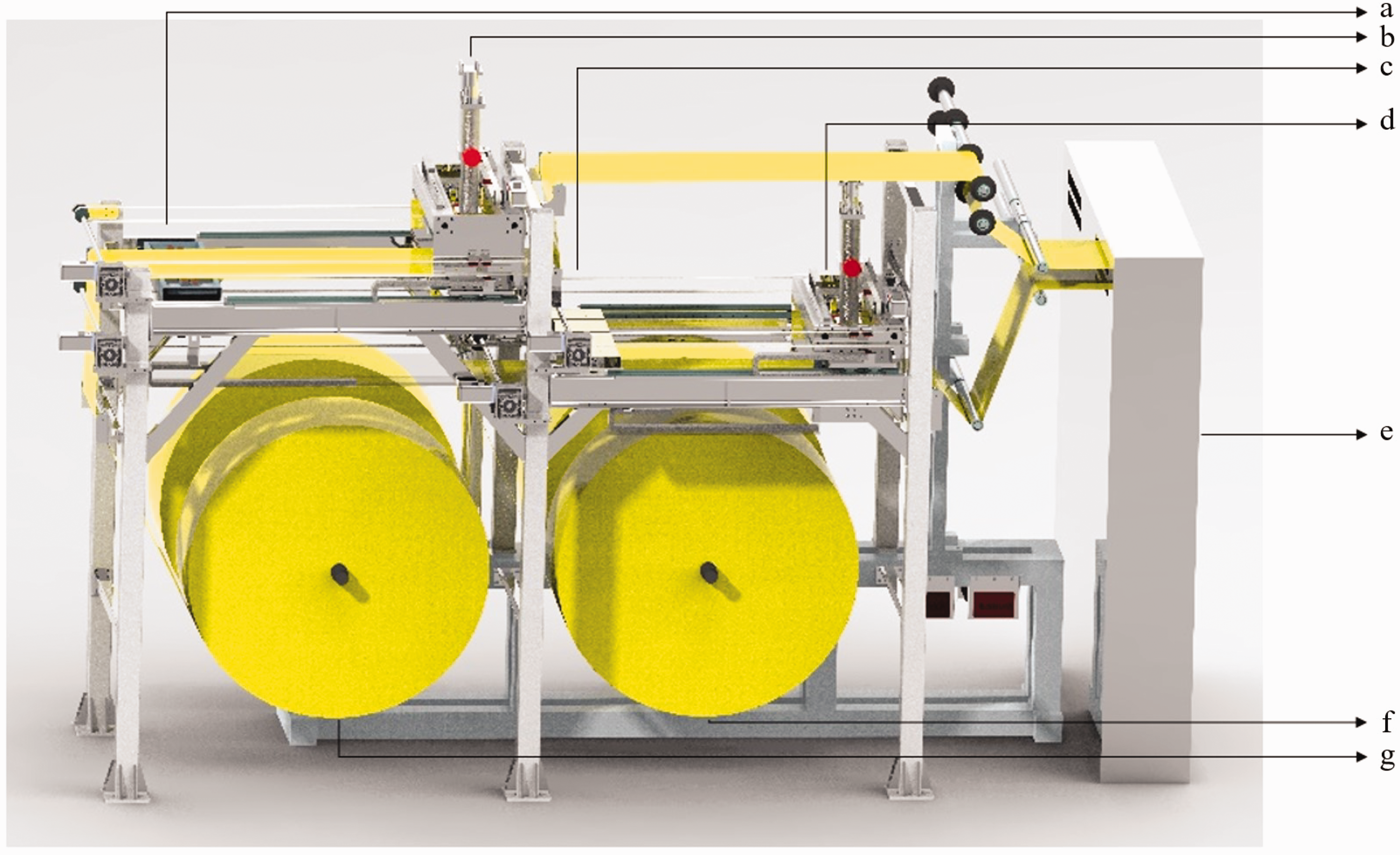
Overall equipment design diagram: (a) metal detection device 1; (b) metal removal device 1; (c) metal detection device 2; (d) metal removal device 2; (e) crusher room; (f) wood pulp roll 2 and (g) wood pulp roll 1.
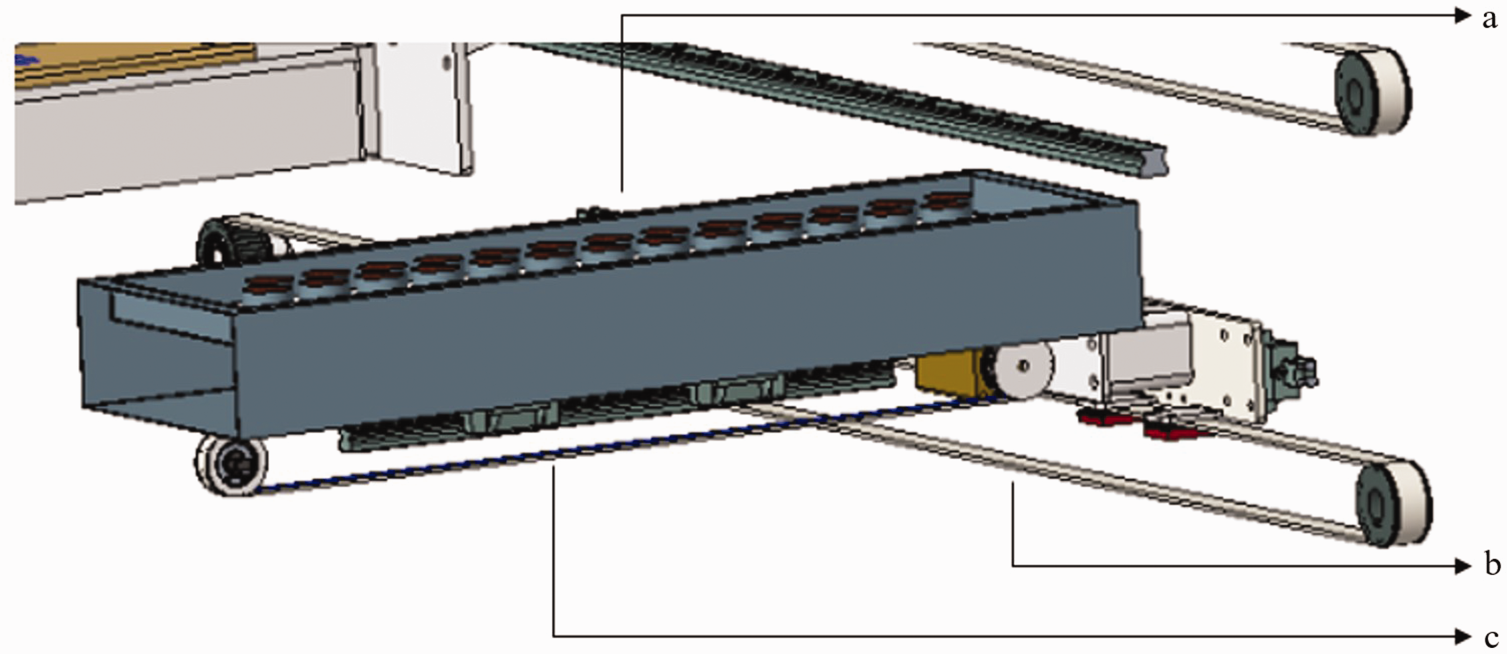
Metal detection device: (a) metal detection area; (b) X-axis motion device and (c) Y-axis motion device.
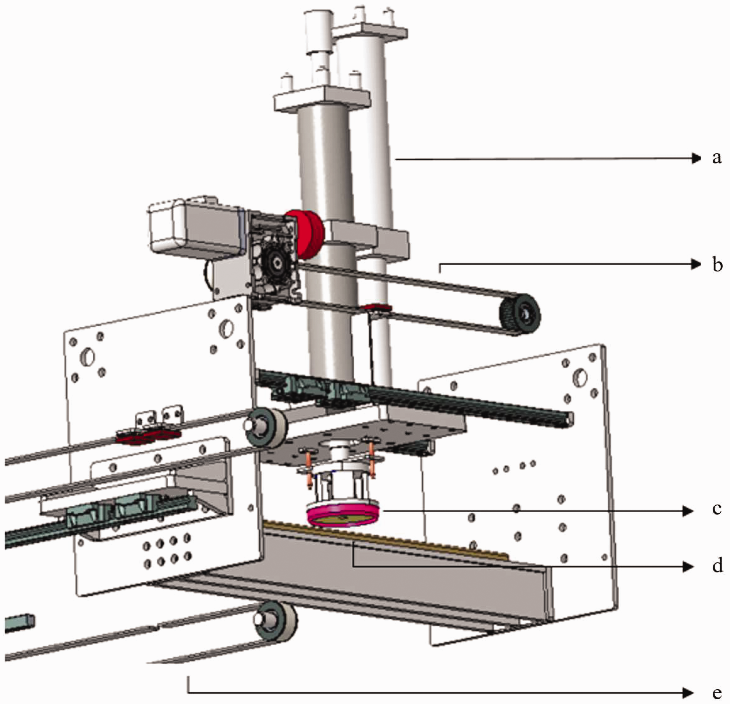
Metal removal device: (a) pneumatic–hydraulic booster cylinder; (b) Y-axis motion device; (c) cutter; (d) PP wear-resistant plate and (e) X-axis motion device.
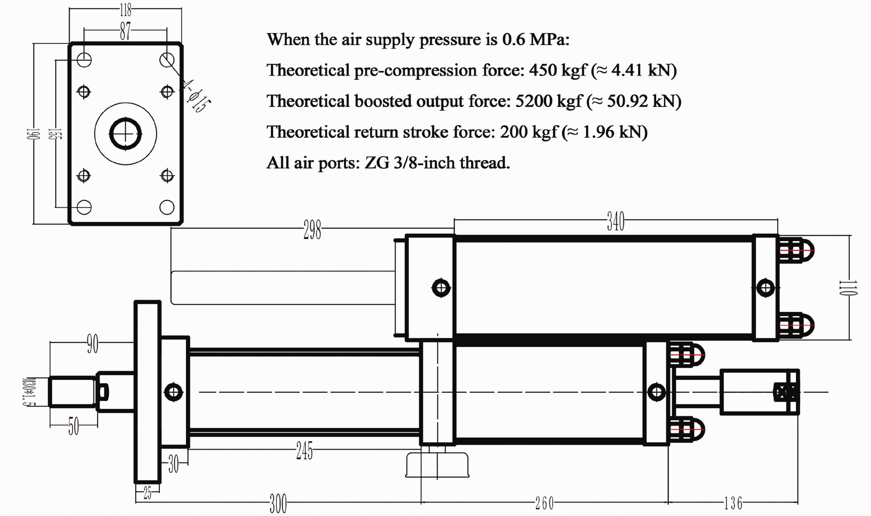
Pneumatic–hydraulic system parameters.
The life expectancy of the coil is 3–5 years. Due to the high requirement for detection accuracy, it needs to be calibrated every 4 months. When the coil detection accuracy decreases and cannot be restored by calibration or physical damage such as cracks and broken wires occurs, the coil needs to be replaced. The model of the pneumatic pressurization system is MPT80X50-20L-5T-50A, and the working temperature is −20 to −80°C. It is necessary to avoid the aging of the seal caused by high temperature, and the O-ring or piston ring needs to be replaced every 6 months.
The width of the wood pulp roll is 48 cm, with a thickness of 0.9 mm and a basis weight of 756.66 g/m2. After unwinding, it is fed into the crusher room, and the conveyor speed is 11–16 m/min. The wood pulp rolls 1 and 2 are alternately fed into the system. When the optical device detects that wood pulp roll 1 is nearly used up, the roll change function is activated. Wood pulp roll 1 starts to decelerate until it reaches zero speed, whereas wood pulp roll 2 gradually accelerates from a stationary state to the maximum speed. This ensures a constant wood pulp feeding rate and guarantees the normal operation of the downstream production processes.
Under normal operating conditions, wood pulp roll 1 is unwound and enters the crusher room, whereas wood pulp roll 2 remains stationary. If wood pulp roll 1 contains metal impurities, the Programmable Logic Controller (PLC) system will send a signal to the crusher room to stop the unwinding of wood pulp roll 1 when it passes through metal detection device 1. The metal detection device 1, controlled by motors, moves along the track in both the X- and Y-axes to precisely identify the coordinates of the metal impurities within the wood pulp roll. These coordinates are then fed back to metal removal device 1, and the metal detection device 1 returns to its starting point.
Then, metal removal device 1 moves along the X- and Y-axis tracks to the coordinates of the metal impurity, controlled by motors. The pneumatic–hydraulic booster cylinder drives the cutter to remove the area of the wood pulp roll containing the metal impurity. The cut portion will get stuck in the circular knife slot. The pneumatic–hydraulic booster cylinder is then moved to the collection area. Using the small pneumatic cylinder inside the circular knife, the cut wood pulp portion stuck in the knife slot is pushed into the collection area. Finally, metal removal device 1 returns to its starting point.
Metal detection device 1 moves along the X-axis to recheck the area that has been cut. If metal impurities are still present, the removal process is repeated until the metal impurities are completely eliminated. During the metal detection and removal process of wood pulp roll 1, the standby wood pulp roll 2 continues to operate. Metal detection device 2 and metal removal device 2 perform detection and removal operations on the metal impurities in wood pulp roll 2.
Metal defect localization and edge-aware adaptive cropping optimization algorithm
In the material production process, metal detectors use electromagnetic induction technology to detect metal defects within materials. This process relies on the interaction between the varying magnetic field generated by the detector and the metal objects. When alternating current passes through the coil of the detector, a dynamic magnetic field is created around the coil. If a metal object enters this magnetic field, eddy currents will be induced within the metal. These eddy currents generate a secondary magnetic field, which interferes with the original magnetic field of the detector. This interference causes changes in the electromagnetic characteristics of the coil, particularly in its impedance.
Specifically, the impedance of the coil is closely related to the characteristics of the surrounding magnetic field. When the magnetic field of the eddy currents interacts with the original magnetic field, the total magnetic flux in the coil changes, leading to a variation in impedance. This change affects the current within the coil, ultimately causing a measurable voltage change, which is represented as a signal waveform. When the peak value of the signal waveform detected by the coil exceeds the set threshold k, it indicates the possible presence of metal defects.
Calculation of coil coordinates
The initial position of the detector is set as d0, the material’s movement speed is v, the radius of the coil is
For the coils in the upper row (numbered i = 1, 2, …,N):


For the coils in the lower row (numbered j = N + 1, N + 2, …, 2N):


When the signal waveform peak values of any two coils 
Edge-aware adaptive cropping optimization algorithm
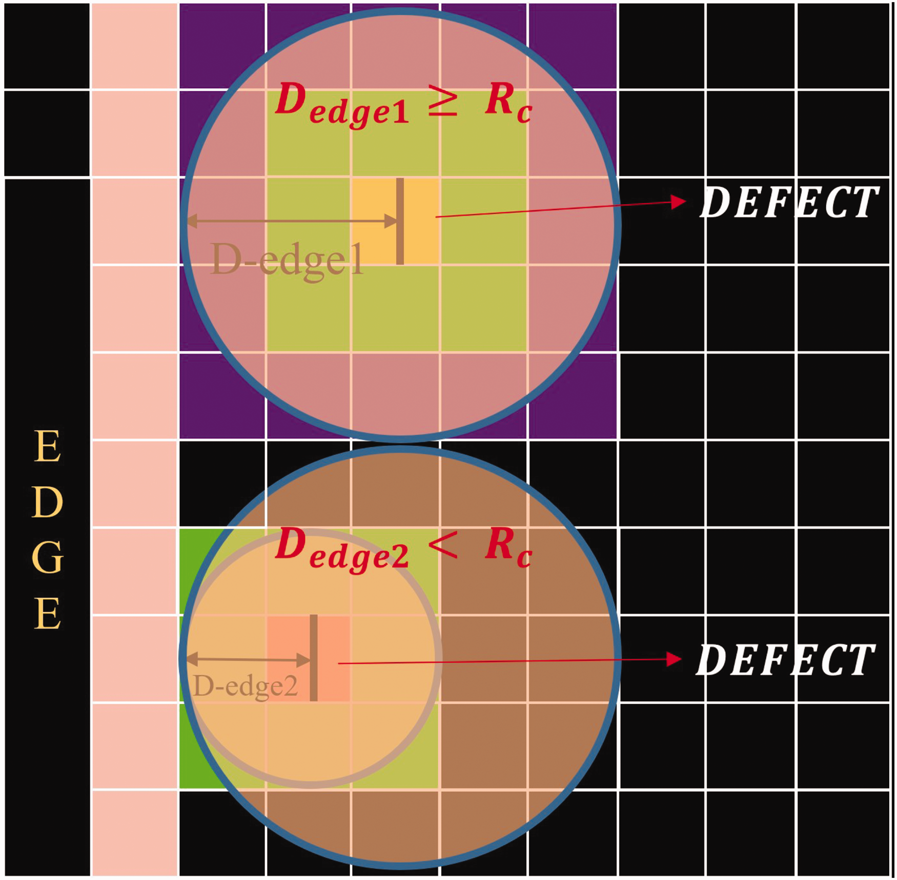
In the cutting process of fabric materials, if the cutting area is too close to the boundary, it may cause uneven force distribution during material transportation, leading to distortion, deformation, or even jamming of the equipment. Therefore, designing an algorithm that can effectively remove defects while avoiding cutting near the fabric edges is a key issue for production line optimization. To maximize defect removal and prevent damage to the material’s edges, we propose the “edge-aware adaptive cropping optimization algorithm.”
This algorithm precisely determines the defect position and optimizes the center and radius of the cutting circle. It ensures that while removing defects, the cutting area does not get too close to the material’s edge, thus preventing damage to the material’s edges during the production process and avoiding deformation of the fabric during transportation.
(1) Determination of the minimum enclosing circle
After the defect location is completed, the first step is to determine the minimum enclosing circle for each defect. The calculation of the minimum enclosing circle is based on the geometric shape of the defect, with the goal of finding the smallest circle that can fully enclose the defect. Specifically, for each defect Pi (xi,yi), the center Ci (xc,yc) and radius Rmin of its minimum enclosing circle can be determined through the following steps.
Determining the boundary points of the defect. To calculate the minimum enclosing circle for a defect, it is essential to first identify the boundary points that define the geometry of the defect Calculating the circumcenter and radius. The minimum enclosing circle that surrounds these boundary points is calculated using geometric methods, where the center Ci (xc,yc) and radius (2) Cutter center positioning

After determining the minimum enclosing circle, the initial selection of the cutting area is based on the center of the enclosing circle. The radius Rc is slightly larger than or equal to Rmin to ensure that the defect is fully covered. The initial cutting circle is defined as

The radius (3) Boundary detection and cutting center optimization
After the initial selection of the cutting area, the next step is to detect whether the cutting circle will contact or cross the material boundary. To prevent the cutting area from affecting the integrity of the material’s edge, it is essential to ensure that no part of the cutting circle touches the edge of the fabric. The minimum distance from the cutting circle’s center to the material boundary is defined as
The cutting condition is as follows:
In order to avoid the cutting area touching the boundary, the center of the cutting circle must be optimized. The optimization objective is to move the center
Optimization workflow for clipping center position.
The new cutting circle center 
The optimization steps are as follows.
Calculate the normal direction. Compute the direction vector Move along the normal direction. Move the center
Finally, the optimized cutting circle center position (4) Cutting execution and edge protection
After optimizing the cutting circle center, the cutting process can begin. The final definition of the cutting circle is

The cutting area satisfies the following conditions:

Through this cutting operation, the defect will be removed completely, whereas the material edge remains intact, preventing issues such as fabric distortion or equipment jams caused by incomplete edges during subsequent transport.
Experimental results and analysis
Overall equipment
The final manufactured intelligent metal detection and removal automation equipment is shown in Figure 10. Taking the pulp roll feeding as an example, when the fed pulp roll does not contain metal impurities, the entire equipment operates normally, and the metal removal device is in its initial position, as shown in Figure 11. At the same time, the corresponding pulp roll metal detection indicator light remains off, as shown in Figure 12.
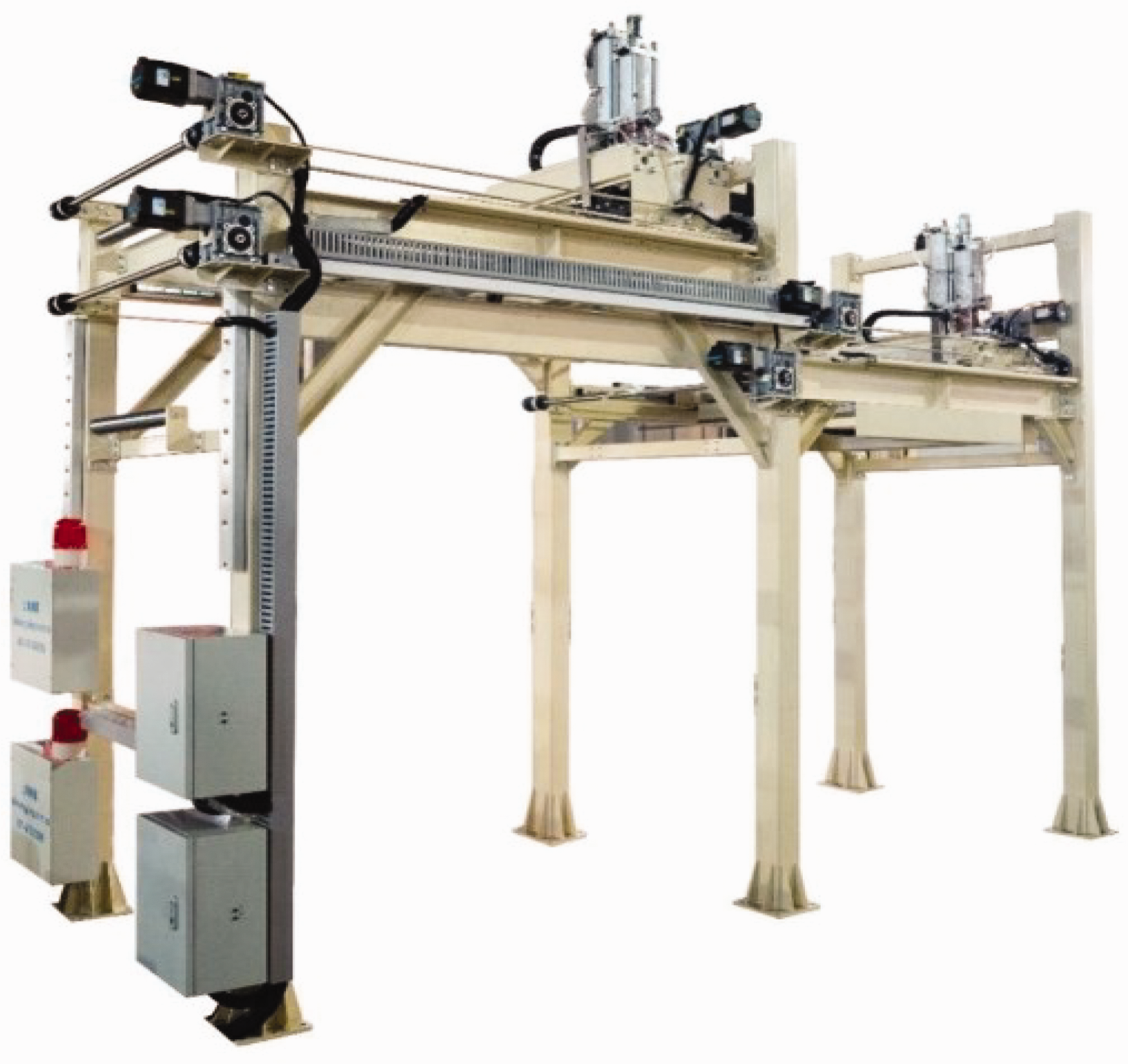
Overall equipment diagram.
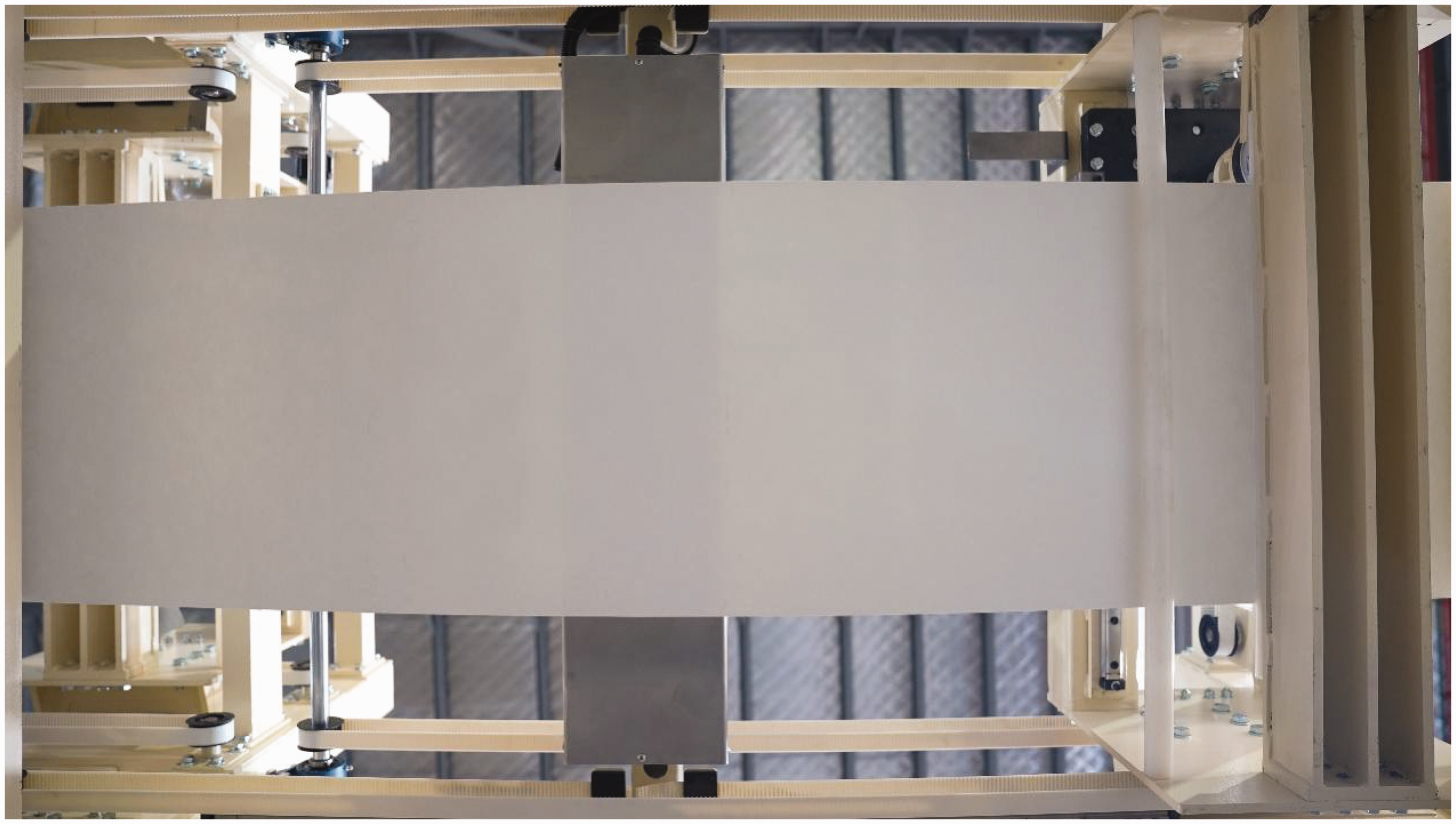
Equipment operation diagram with no metal presence.
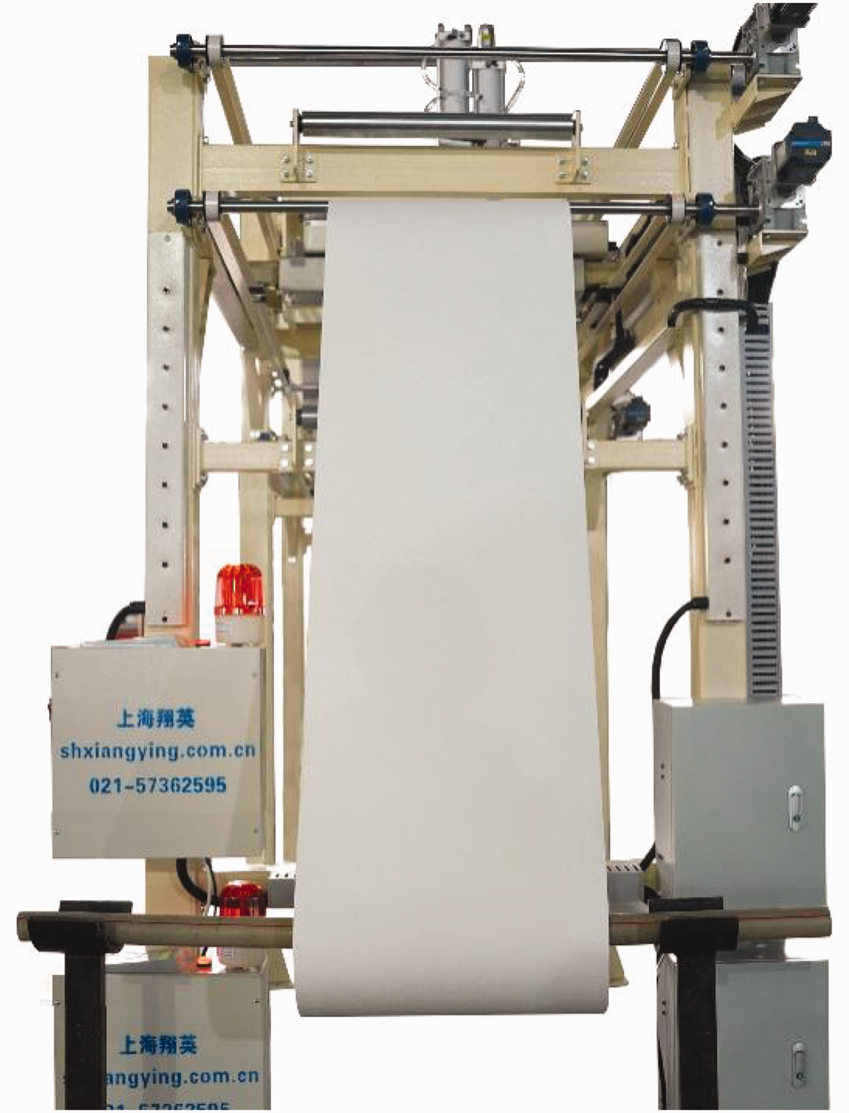
Indicator light status diagram.
Metal detection
Taking the pulp roll feeding as an example, when the fed pulp roll contains one or more metal impurities, the operation of the entire equipment is observed.
Single metal detection
When the fed pulp roll contains a single metal impurity, such as iron with a diameter of 1.2 mm, as shown in Figure 13(a), the metal detection device accurately locates the metal’s XY coordinates. Based on the edge-aware adaptive trimming optimization algorithm, the minimal enclosing circle of the metal and the cutter’s center coordinates are determined.
Single metal detection: (a) pulp roll before metal removal; (b) pulp roll after metal removal; (c) removed metal and (d) enlarged metal.
The metal removal device then moves along the XY-axis from its initial position to the cutter’s center coordinates. The device lowers and presses the pulp roll, as shown in Figure 14(a,b). Under the driving force of the pneumatic–hydraulic press cylinder, the cutter removes the metal-contaminated region of the pulp roll. The removed section of the pulp roll is trapped in the circular knife groove, as shown in Figure 14(c).
Metal removal process: (a) metal removal device at the initial position; (b) metal removal device at the metal coordinate location; (c) metal removed and (d) metal removal device carrying the metal back to the initial position.
The metal removal device then moves the contaminated pulp roll back to its initial position. Using a small pneumatic cylinder inside the circular knife, it pushes the trapped section of the pulp roll down into the collection area, ensuring unified collection of the cut pulp roll section, as shown in Figure 14(d). The pulp roll after metal removal and the removed metal are shown in Figures 13(b–d).
Multimetal detection
When the feeding pulp roll contains multiple metals, the metal detection device performs the initial detection and precisely locates the first metal in the X-axis direction, as shown in Figure 15(a). Based on the edge-aware adaptive cropping optimization algorithm, the minimum enclosing circle of the metal and the center coordinates of the cutter are determined. The metal removal device then moves to the center coordinates, cuts the area with metal from the pulp roll, and collects it, as shown in Figure 15(b). The pulp roll after the first metal removal is shown in Figure 15(c). The metal detection device performs a reinspection and locates the coordinates of the second metal in the X-axis direction, and the metal removal device removes it, as shown in Figure 15(d,e). The metal detection device continues to perform reinspections until all metals are removed, as shown in Figure 15(f).
Multimetal detection: (a) initial metal detection; (b) initial metal removal; (c) pulp roll after initial metal removal; (d) secondary metal detection; (e) pulp roll after secondary metal removal and (f) pulp roll after all metals have been removed.
The tested intelligent metal detection and disposal automation equipment demonstrates high sensitivity. When a pulp roll contains single or multiple metal impurities, the metal detection device performs both initial and rechecks to accurately locate the coordinates of the metals. The metal removal device then precisely removes the areas of the pulp roll containing metal. The total power of the metal detection and removal device is 6 kW. When the metal-containing wood pulp roll passes through the metal detection device, the device will immediately alarm, and the total time for a metal to complete the detection and removal is about 30 s. In addition, while one pulp roll is undergoing metal removal, another pulp roll is fed in at an accelerated rate, ensuring a constant pulp feed rate and high production efficiency. The entire detection process has been recorded in a video and added to the supplementary material.
Performance
To systematically evaluate the proposed triangular-coil detection system, we conducted controlled experiments with iron impurities of four diameters (1.2, 1.4, 1.6, and 2 mm) under varying vertical distances (5, 10, and 15 mm). For each metal size, detection accuracy was calculated by averaging 45 test cycles: 10 edge placements (single and overlapping), 10 midwidth placements (single and overlapping), and 5 randomized positions. Crucially, successful detection required not only identifying the presence of metal but also precisely localizing its position within the fabric roll. The results (Figure 16) demonstrate significant variations in accuracy depending on both metal size and detection distance, with optimal performance observed at 10 mm vertical distance. This rigorous validation protocol ensures statistical robustness and industrial relevance.
Detection accuracy profiles of iron fragments under varying vertical distances.
Experimental results indicate a nonlinear relationship between vertical detection distance and system accuracy, with optimal performance observed at 10 mm. At close proximity (5 mm), intensified electromagnetic coupling induces eddy current saturation in smaller targets (1.2 mm), whereas heightened sensitivity to fabric vibration compromises positional stability. Conversely, at extended distances (15 mm), quadratic decay of magnetic flux density combines with environmental electromagnetic interference to degrade detection reliability. Crucially, the 15 mm configuration exhibits significant positioning inaccuracies, particularly in edge-overlapping scenarios. Future implementations could integrate real-time distance compensation algorithms to dynamically adjust coil excitation parameters, thereby sustaining optimal detection–localization synergy under varying production line conditions.
The primary goal of this study is to enhance the accuracy and automation of metal detection in nonwoven fabric production lines, while performance optimization serves as the key driver for its industrial implementation. Conventional industrial metal detection systems primarily rely on single-coil electromagnetic detection, which has notable limitations in sensitivity, accuracy, and automation capabilities. Most existing systems only provide alarm notifications, requiring manual intervention for impurity removal, which interrupts production and reduces efficiency. Some advanced systems use linear-coil (two-coil) or rectangular-coil (four-coil) arrangements to improve sensitivity, but they still struggle with detection blind spots and limited automation. To highlight the advantages of the proposed system, we compare different metal detection methods in Table 3.
Comparison of metal detection methods in industrial applications
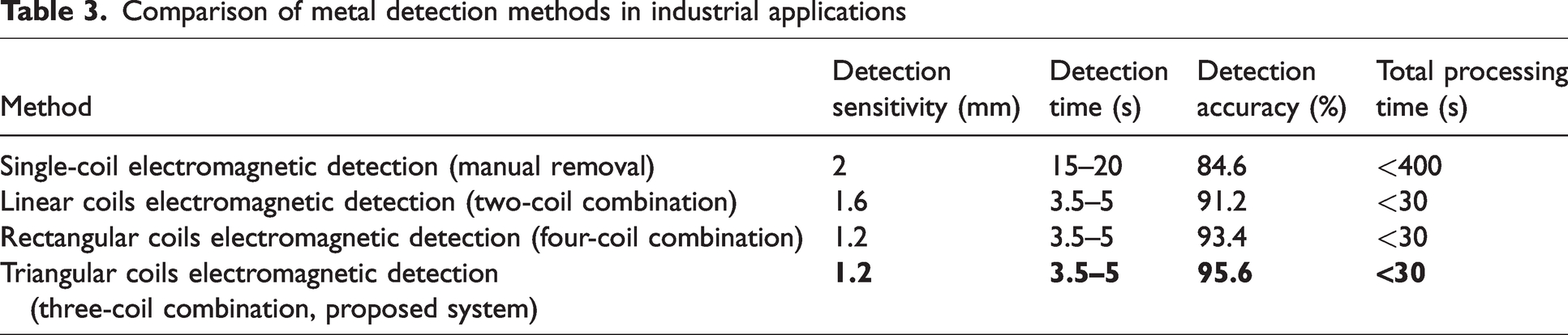
Our system achieves higher detection accuracy (95.6% versus 84.6% in traditional methods) and significantly reduces total processing time from 6 minutes (manual detection and removal) to just 30 seconds: a 10-fold efficiency improvement. Unlike conventional methods that rely on manual removal after detection, our system integrates fully automated impurity localization, removal, and reinspection, ensuring continuous production without frequent interruptions, making it highly suitable for industrial-scale applications.
Conclusion
This paper has addressed the issue ferrous of metal impurities in pulp rolls in the nonwoven industry by designing and implementing an intelligent metal detection and removal automation equipment based on the “edge-aware adaptive clipping optimization algorithm.” The device optimizes the arrangement of the detection coils by employing a triangular configuration, significantly enhancing the uniformity and sensitivity of the magnetic field, thereby improving the detection accuracy for iron-based contaminants. Using the edge-aware adaptive clipping optimization algorithm, the location of metal impurities is accurately identified, and the center and radius of the clipping circle are optimized to ensure that the clipping area does not contact the material’s edges during impurity removal, thereby avoiding material deformation and equipment jamming during production. To achieve precise and efficient impurity removal, a pneumatic–hydraulic driven cutting mechanism was developed, which ensures both accuracy and continuity in production. Experimental results confirm that the proposed system can detect and remove iron particles as small as 1.2 mm in diameter, significantly reducing processing time and enabling fully automated impurity handling. The system is primarily optimized for detecting ferrous metals, leveraging their strong magnetic response to achieve high sensitivity and positioning accuracy. However, its sensitivity to nonferrous metal contaminants remains limited.
This research presents a viable technical solution for improving automation in the nonwoven industry, with broad industrial applicability and market potential. The integration of automated impurity removal not only eliminates manual intervention but also reduces total processing time by a factor of 10, ensuring uninterrupted production flow. Future research can further expand on the device’s intelligence and adaptability, particularly by integrating machine learning algorithms for automated optimization to improve the system’s responsiveness in complex production environments. In addition, extending the system to detect and remove other types of nonmetallic impurities, as well as optimizing the cutting process for different material compositions, will push the device toward multifunctionality, further enhancing production efficiency and product quality. However, the current system is not suitable for detecting metal impurities smaller than 1.2 mm. Industrial data suggest that such small contaminants are rarely encountered in practical production scenarios. While increasing detection sensitivity could theoretically enhance performance, it would also introduce significant noise interference, making it impractical under industrial conditions. In addition, the experimental validation conducted in this study was based on manually placed ferrous impurities, which ensured controlled and repeatable testing conditions. Future research may explore the use of adaptive frequency modulation techniques, as well as evaluate the system’s performance in detecting naturally occurring contaminants, such as irregularly shaped, partially embedded, or clustered metal particles, which would provide meaningful insights for in situ validation under real production scenarios.
Footnotes
Declaration of conflicting interests
The author(s) declared no potential conflicts of interest with respect to the research, authorship, and/or publication of this article.
Funding
The author(s) disclosed receipt of the following financial support for the research, authorship, and/or publication of this article: This work was supported by the financial support from the National Key Research and Development Program of China (No. 2022YFB4700600), the National Natural Science Foundation of China (62171116), the Fundamental Research Funds for the Central Universities and Graduate Student Innovation Fund of Donghua University (CUSF-DH-D-2022044).
Supplementa material
Supplemental material for this article is available online.