
Abstract
Three-dimensional (3D) braided composites are extensively utilized in aerospace laminated composites owing to their superior out-of-plane shear properties and interlaminar delamination resistance compared with two-dimensional (2D) textile laminated composites. However, existing laminate models remain incapable of elucidating the enhancement mechanisms underlying the superior out-of-plane shear properties of 3D braided architectures. Understanding the influence of 3D braided yarn architecture on out-of-plane failure mechanisms is critical for enabling rapid design and batch-efficient manufacturing of aerospace composite components. This study has established a refined mechanical model for 3D braided laminated composites by integrating Hashin3D failure criterion with cohesive traction-separation law. The model quantitatively decoupled the respective contributions of braided architecture and interlaminar interfaces to out-of-plane failure. Results reveal that 3D braided laminated composites exhibit mixed failure modes of buckling and delamination, whereas 2D textile laminated composites failed predominantly through interfacial delamination. This divergence stems from the reduced interlaminar interfaces in 3D braided laminated composites mitigated catastrophic delamination risks. Concurrently, the interlaminar interlacing yarn architecture suppresses interfacial cracks propagation thereby enhancing out-of-plane properties.
Keywords
Laminated structures are employed extensively in composite material components in aerospace, rail transportation, and defense composite components.1,2 However, two-dimensional (2D) textile laminated composites are highly susceptible to interlaminar delamination under out-of-plane loading, often resulting in catastrophic failure. Replacing 2D textile laminated composites with three-dimensional (3D) braided laminated composites, which introduce interlaminar interlacing yarn architecture and reduce interlaminar interface counts,3,4 represents a critical strategy for enhancing out-of-plane shear properties in composite laminated composites. 5 Hu et al., 6 Sun et al., 7 and Ao et al. 8 investigated interlaminar properties and damage mechanisms in 2D textile laminated composites through multiscale analyses, including crack propagation, impact delamination, and static interlaminar shear failure under quasi-static and impact loading. In addition, interfacial delamination dominated the failure mode of 2D textile laminated composites, serving as the primary driver of structural instability. Johannes Reiner et al. 9 characterized the out-of-plane mechanical properties of intralaminar regions and interfaces in 3D braided laminated composites under impact, quasi-static, and thermal–solid coupling. Results showed that the out-of-plane mechanical failure modes of 3D braided were intricately governed by yarn architectures. But those models fail to capture multivariate correlations between 3D braiding processes, mesoscopic yarn architecture, and performance enhancement mechanisms in 3D braided composites,9-11 hindering accurate characterization of dynamic responses to braiding process variations, particularly braiding angle–thickness coupling effects that drive divergence in mesoscopic yarn architecture.
However, existing models fail to accurately quantify the performance implications of interyarn mutual compression in braided architectures during the 3D braiding process. Key limitations include the following. (1) Yarn trajectory-based methods12,13 dynamically characterized yarn geometric evolution (e.g., radius-dependent textile distribution in circular pipes) but lacked matrix-integrated finite-element (FE) mechanics modeling. (2) Digital element methods 14 captured local yarn friction/compression effects at prohibitive computational cost, while omitting matrix-inclusive FE models for dynamic yarn architecture evolution. Conversely, multiscale representative volume elements (RVEs) have been established with periodic boundary conditions for circular 2D textile structures.15-18 Through tension and three-point bending simulations, they analyzed constitutive behavior, damage mechanisms, and crack propagation. Nevertheless, these 2D laminated composites remain highly susceptible to delamination under out-of-plane loading, exhibiting fundamentally distinct mechanical responses from 3D braided composites.
Furthermore, in four-step 3D braided preforms, yarn cross-sections maintain near-circular geometry with minimal structural deformation under mutual compression. This contrasts markedly with circular braided composites, where flattened yarn profiles exhibit significant thickness fluctuations during width variations, causing pronounced single-ply thickness inconsistencies that degrade performance. Multiscale models have been developed in the literature analyzing anisotropic mechanical properties and progressive damage in four-step 3D braided structure.19-23 Through uniaxial tensile and compression experiments, they characterized stress distribution and fracture patterns during failure. However, four-step 3D braiding primarily suits simple geometries (e.g., prismatic beams) with minimal yarn deformation, typically requiring twisting to achieve near-unity yarn aspect ratios. This contrasts fundamentally with circular 3D braiding in yarn architecture, material behavior, and processing parameters. Micro-CT was combined with yarn trajectory prediction algorithms to model yarn extrusion deformations, demonstrating enhanced predictive accuracy in multiscale mechanical analyses.24,25 Nevertheless, such CT-based approaches lack dynamic yarn architecture evolution modeling during braiding, preventing comprehensive characterization of structure–property relationships.
This study first established a mesoscale mechanical model for 3D braided laminated composites incorporating yarn architecture structural evolution during circular 3D braiding. A comparative analysis was then conducted on the effects on out-of-plane failure behavior of critical factors, including interlaminar interfaces, yarn architecture, stacking layer, and braiding angles. Parametric analysis revealed how interlaminar interfaces, yarn architecture, ply stacks, and braiding angles govern out-of-plane failure, providing design guidelines for data-driven optimization of laminated structures for aerospace applications.
Materials and experiment
The braided preform was fabricated using a 352-carriers circular 3D braiding machine capable of forming four-layer yarn-interlaced architectures. As shown in Figure 1(a), a 153-mm-diameter round-straight-tube mandrel guided the braiding process. As indicated by Table 1, raw materials (T700-grade carbon fiber yarns and epoxy resin) were sourced from ZhongFuShenYing and AVIC Composites (China). The laminated structures were formed via ply-stacking the braided preforms and consolidated via vacuum-assisted resin transfer molding (VARTM). Then, specimens were machined via CNC precision machining. For comparison, 2D textile laminates were manufactured from identical plain-weave fabrics, consolidated to equivalent thicknesses as the 3D braided composites.
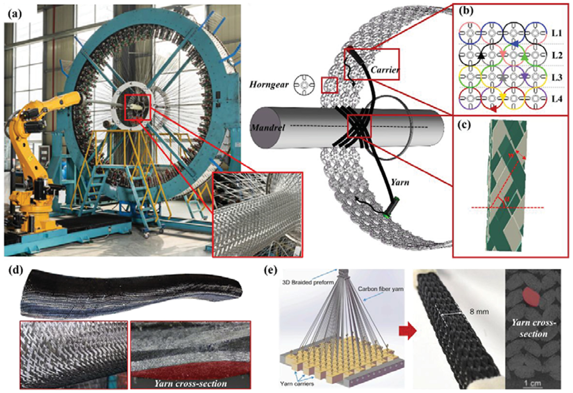
Characteristics of circular 3D braiding process and comparison with four-step 3D braiding. 5 (a) Circular 3D braiding machine and forming process. (b) Crosslinking trajectory of 3D braiding spindle. (c) 3D braiding main structure parameters. (d) Circular 3D braided thin-walled structure. (e) Four-step 3D braided constant cross-section beams.
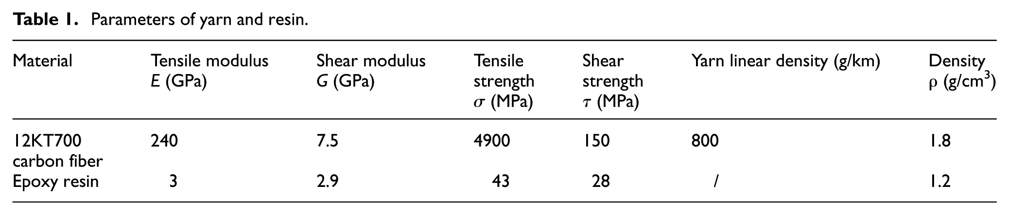
Parameters of yarn and resin.
Specimen braiding
As shown in Figure 1(a), the 352-carriers circular 3D braiding machine has four concentric rings of horn gears that drive spindle carriers along eight color-coded trajectories (Figure 1b) through synchronized intermeshing rotation of adjacent gears during braiding. The annular arrangement of horn gears (L1–L4) generates serpentine carrier trajectories along the circumferential path of the braiding machine's annular frame, defining the fundamental mechanism of annular 3D braiding. The eight color-coded trajectories represent interlacing patterns of eight yarn sets during 3D braiding, progressively forming a 3D yarn architecture through mutual interlocking. During robotic-arm-driven mandrel withdrawal, multiple yarn carrier sets traverse designated trajectories, forming an interlaminar interlacing yarn architecture. Tension from spindle carriers ensures the yarn architecture consolidates tightly against the mandrel surface at the preset braiding angle.
As defined in Figure 1(c), the angle between fiber orientation and mandrel axial represents braiding angle α; the area fraction of yarn excluding inter filament gaps per unit cell represents the coverage ratio k. These constitute fundamental process parameters of 3D braided composites. 26 As shown in Figure 2(a), the specimens were made of T700-grade carbon fiber and epoxy resin, and cured by resin vacuum infusion RTM molding. Critically, comparative experiments employed identical-specification plain weave fabrics (12K T700 carbon fiber) with matching areal weight (328 g/m2), monolayer thickness (0.3 ± 0.02 mm), yarn linear density, and yarn density to those used in 3D braiding. The key parameters are detailed in Table 1, where the elastic modulus E and shear modulus G defined the constitutive tensor in the mechanical model, whereas tensile strength σ and shear strength τ determined the damage initiation criteria and stiffness degradation model. For composites with flattened yarn cross-sections, the established research confirms distinct constitutive relationships between dry yarns and consolidated composites. 27
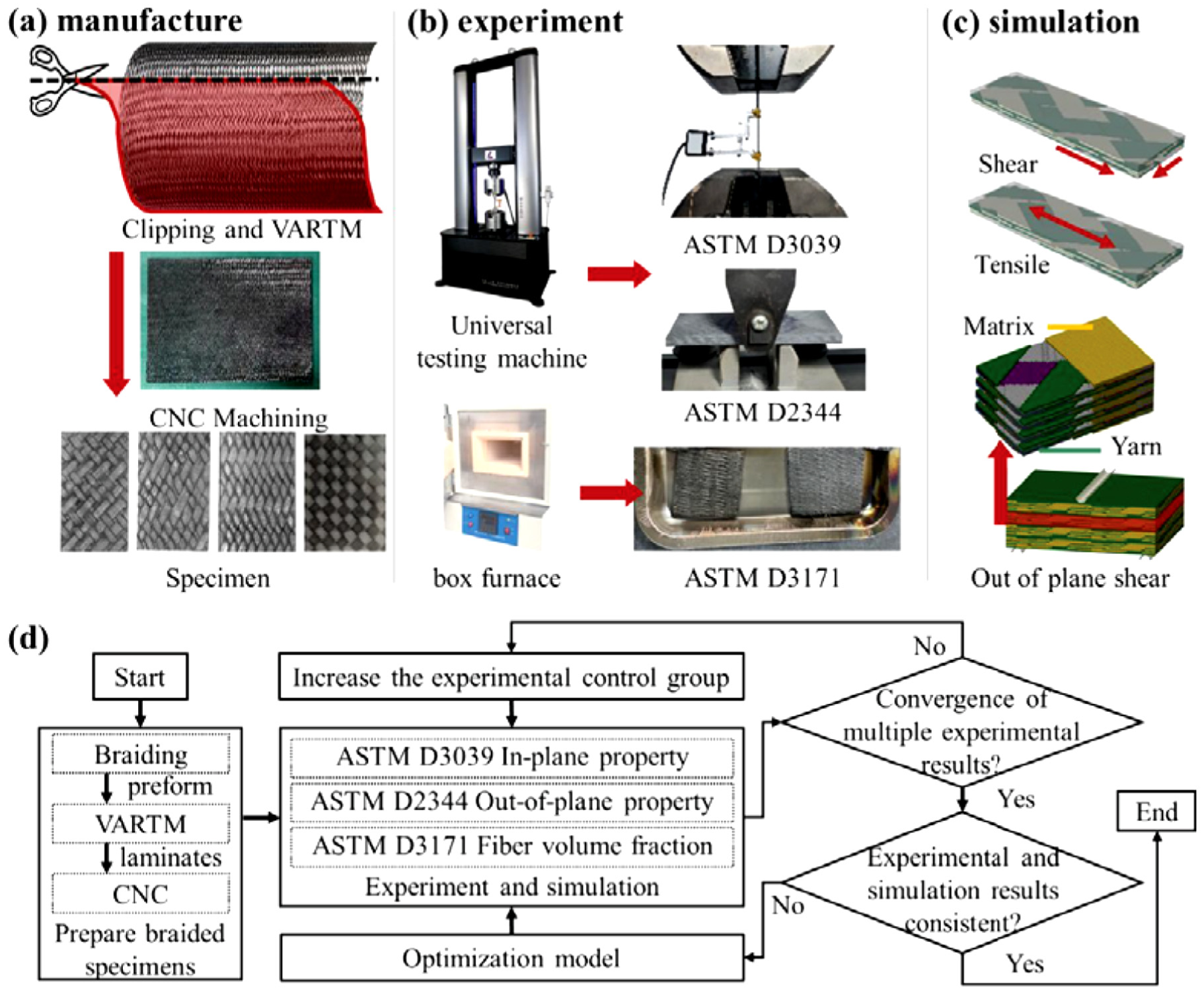
Experimental design and simulation comparison. (a) Manufacturing of 3D braided specimens. (b) Experiments of tensile/shear properties and fiber volume fraction. (c) Simulation of tensile/shear properties. (d) Experiment and simulation process.
Mechanical testing
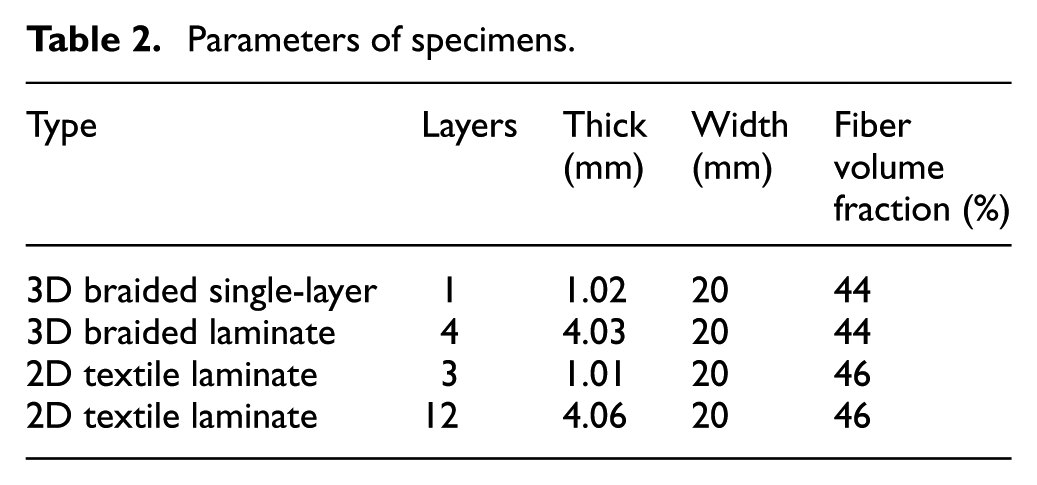
Tensile testing was performed according to ASTM D3039 and ASTM D3518 to detect elastic modulus, strength, and failure modes, and fiber volume fraction was quantified via acid digestion per ASTM D3171, with five replicates per test group. As indicated by Table 2, the specimens measured 180 mm (length) × 20 mm (width) × 1 mm (thickness), manufactured using unitary 3D braided composite. As shown in Figure 2(b) and (c), experimental and simulation configurations demonstrate multiscale model validation through tensile response correlation. The validated model subsequently derived the orthotropic engineering constants for constitutive analysis, then employed the validated model to derive the orthotropic stiffness tensor for constitutive analysis.
Parameters of specimens.
Out-of-plane shear testing was performed according to ASTM D2344, defining three failure modes: interlaminar delamination, buckling-induced compression–tension damage, and elastic–plastic deformation. To mitigate size effects from free-edge cracks and interfacial anomalies, specimens with extended free-end dimensions were employed, enabling larger interfacial damage and crack propagation zones. Figure 2(c) illustrates experimental and simulation configurations. Through simulation-experimental analysis of out-of-plane shear behavior, out-of-plane shear strength, load–displacement responses, and failure modes of 3D braided laminated composites and 2D textile laminated composites were quantified. Subsequently, out-of-plane shear behavior and interlaminar failure mechanisms of 3D braided laminated composites were analyzed by examining fracture morphology and crack distribution using optical microscopy. Concurrently, through layer-by-layer comparison of experimental and simulation results, the temporal stress evolution in multilayer 3D braided yarn architectures and interlaminar interfaces was mapped during shear failure progression, elucidating the out-of-plane shear properties of 3D braided composites. The preparation and experimental process of specimens are shown in Figure 2(d).
Multiscale mechanical modeling of 3D braided composites
The through-thickness architecture of 3D braided laminated composites comprises interlaced yarn architecture and interlaminar interfaces. Their out-of-plane mechanical properties are governed by both constituents.
Multiscale model of 3D braided composites based on yarn structure deformation
As shown in Figure 1(d), geometric variations in the mandrel induce thickness and braiding angle deviations in the 3D braided structure due to its near-net-shape forming characteristics. Consequently, mesoscopic yarn architectures must be computationally modeled with process–structure coupling. Building upon the process–property modeling approach, 28 a mesoscopic yarn architectures model was developed. As shown in Figure 3(a1), a yarn trajectory fast prediction algorithm26,29-31 was used to calculate the yarns’ topological distribution and to predict yarn cross-section deformation under contact constraints based on yarn spacing.32,33
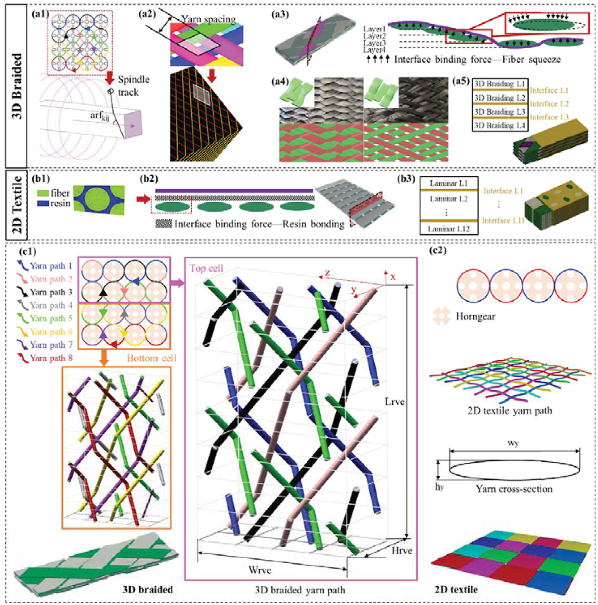
Multiscale modeling of 3D braided laminate and 2D textile. (a1) Solving the yarn topological distribution based on process–property modeling approach of 3D braided composite. 28 (a2) Solving the yarn extruding relationship based on yarn topological spacing. (a3) Solving the lamination law in thickness direction based on the law of yarn interlacing. (a4) Difference of extrusion deformation caused by different yarn spacing: tight on the left and sparse on the right. (a5) Distribution relationship of inner-layer and interlayer structures of 3D braided laminated composites. (b1) 2D textile structure yarn cross-section. (b2) Interfacial distribution between 2D textiles. (b3) Distribution relationship of inner-layer and interlayer structures of 2D textile laminated composites. (c1) Yarn architecture of 3D braided composite. (c2) Fabric structures of 2D textile.
The 3D braided yarn architecture is characterized by

As illustrated in Figure 3(c1), the structure comprises eight distinct yarn systems, where yarn paths 1, 4, 5, and 8 and yarn paths 2, 3, 6, and 7 correspond to counter-moving spindle carrier groups. Trajectory arrows indicate movement directions along the z-axis and ZOY projection plane. Each spindle carrier possesses unique initial phase relationships and interlacing patterns, their out-of-plane undulation is governed by sinusoidal functions of time
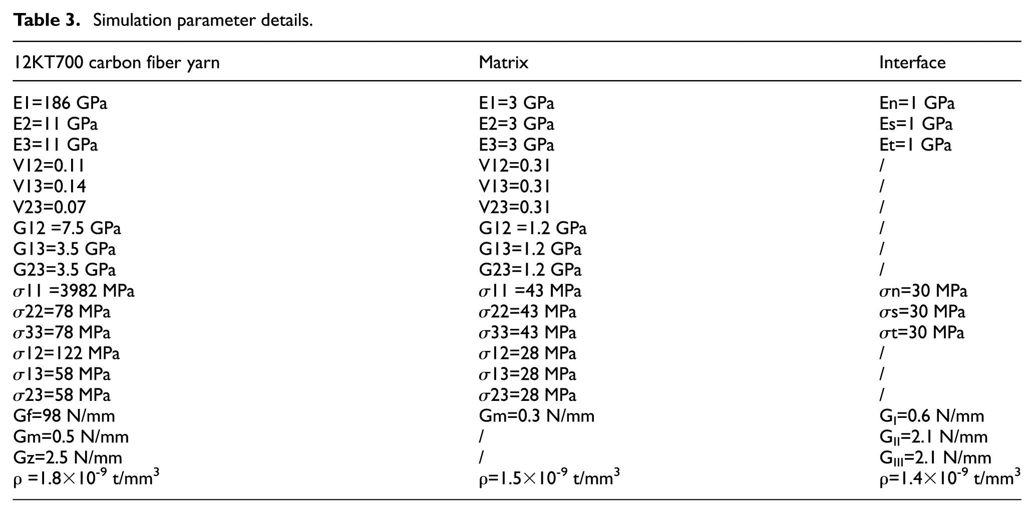
Combining with Figure 3(a4), mutual extrusion between yarns leads to the change of yarn width. The yarn width under extrusion can be obtained by solving the yarn spacing, and the corresponding yarn thickness can be calculated according to the condition that the yarn cross-sectional area is unchanged, so as to predict the thickness change of single-layer braided yarn architecture. The difference caused by different extrusion states is shown in Figures 1(d) and 1(e). As illustrated in Figure 3(a4), contact-induced yarn deformation alters yarn width. This width variation is determined by solving yarn spacing (Figure.3a2), while yarn thickness is derived from constant cross-sectional area assumption, enabling prediction of braided yarn architecture thickness variations (Figure.3a4). Building upon the interlacing topology in Figure 3(a1), the spatial architecture of 3D braided composite was reconstructed to establish the 3D braided RVE. This model was imported into the software TexGen and HyperMesh for FE discretization, yielding ≈ 105 elements per layer after mesh sensitivity analysis. Tensile simulations employed periodic boundary conditions along transverse/longitudinal axes via TexGen. Out-of-plane shear loading followed ASTM D2344 protocols (Figure 2b). The 3D braided fabric structure comprises yarn and matrix phases: yarns were transversely isotropic with orientation-dependent principal axes and matrix is isotropic resin (constitutive properties detailed in Table 3).
Simulation parameter details.
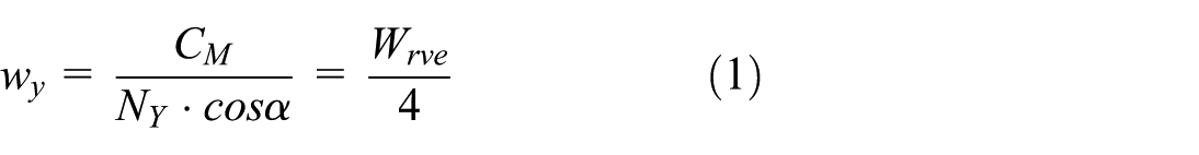
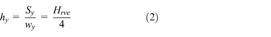
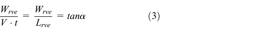
In Equation (1)NY is the carriers/yarns number in every layer of 3D braided equipment, which are involved in braiding process, with a braiding angle of α. The cross-sectional circumference of the mandrel is CM. In addition, wy is the width of the yarn after compression deformation. Equation (1) quantifies mandrel dimension effects on yarn width, as width variation arises from yarn compression deformation. Equation (2) calculates the width wy and thickness hy variations of yarns under mutual compression. Given constant cross-sectional area Sy during braiding, yarn thickness increases as width decreases due to compression. The out-of-plane undulation y follows the sinusoidal function in Equation (4). As shown in Figure 3(c1), it is governed by carrier motion trajectories driven by horn gears. The 3D braiding machine employs eight yarn systems with distinct interlacing paths, color-coded in Figure 3(c1). As shown in Figure 1(a), four annular horn gear layers L1–L4 define carrier trajectories, forming a RVE comprising four stacked laminae with dimensions Hrve (thickness), Wrve (width), and Lrve (length). Equation (3) computes Lrve for a given horngear speed ωg, braiding angle α, and mandrel take-up speed V over time t. The RVE width Wrve is calculated via Equation (1), and consists of top/bottom cells, each containing four yarn systems.
In Equation (4)ωg denotes the horn gear rotational speed, governing the undulating interlacing patterns of yarns within the RVE. In addition, φ represents the initial phase angle of carriers at machine startup, determined by relative positioning of the eight yarns/carriers. This time-independent parameter defines carrier motion kinematics and is indicated by color-coded arrows in Figure 3(c1), with each carrier having distinct initial positions. Directional analysis reveals:
(1) carriers 1, 4, 5, and 8 translate along the +z-axis of the RVE;
(2) carriers 2, 3, 6, and 7 translate along the –z-axis of the RVE.
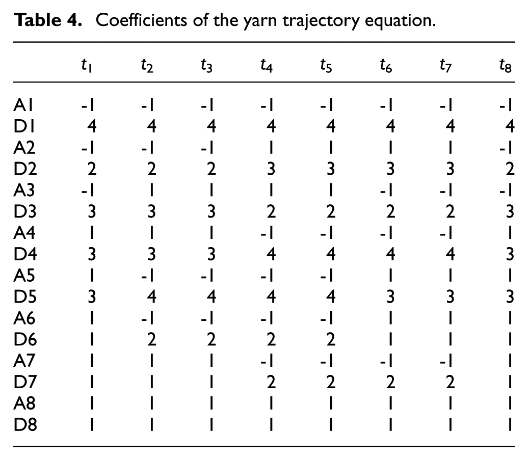
Coefficients A and D in Equation (4) characterize sinusoidal undulation of yarn interlacing, with full parametric evolution per carrier cycle provided in Table 4. Constant B is defined as:
Coefficients of the yarn trajectory equation.
(1) B = +1 for carriers moving along the +z-axis;
(2) B = −1 for –z-axis motion.
Constant C (initial phase) is determined by carrier positions in Figure 3(c1), where the eight-yarn system is modeled as a 4 × 4 spatial matrix. Each matrix row contains two sinusoidal cycles. Then C is defined as:
(1) +z carriers' phase origin at the rightmost matrix column;
(2) –z carriers' phase origin at the leftmost matrix column.
Thus, initial phases are defined as follows. Blue yarn path 1: C1 = 3π/2. Purple yarn path 7: C7 = π. Gray yarn path 4: C4 = 0. Green yarn path 5: C5 = π. Red yarn path 8: C8 = π/2. Pink yarn path 2: C2 = 0. Black yarn path 3: C3 = π. Yellow yarn path 6: C6 = 0. The ABCD sinusoidal coefficients govern yarn interlacing patterns within each cycle. Assigning these coefficients enables discrete reconstruction of 3D braided yarn architecture, resolved into spatial trajectories in the bottom cells and top cells (Figure 3c1). The full horn gear cycle period T = 4π/ω g is divided into eight time intervals Δt = π/2ω g , corresponding to t1–t8 in Table 4.
Mechanical constitutive and progressive damage models
Single-layer 3D braided composites
The following equations formulate material constitutive relations and failure characteristics for 3D braided yarn architecture and matrix:
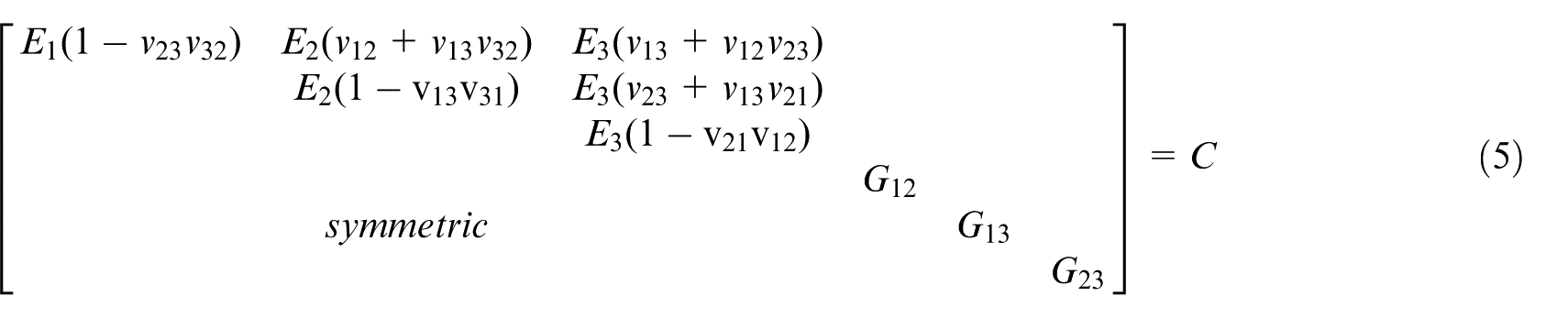
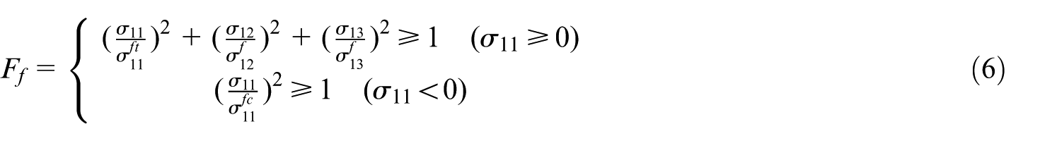
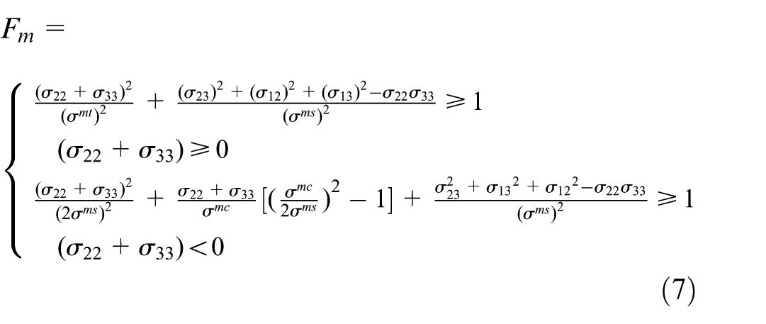
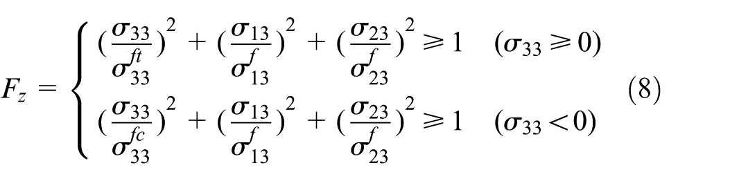
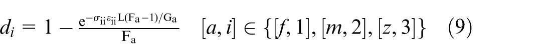
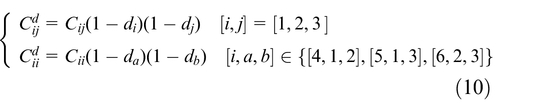
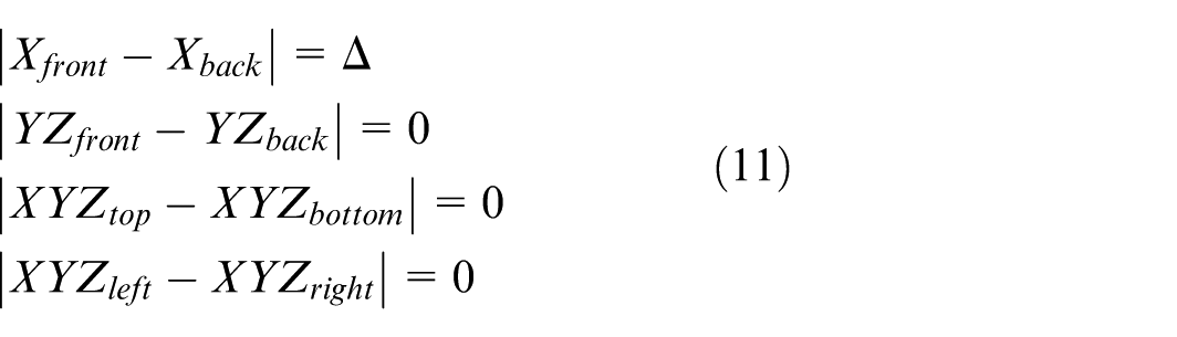
Tensile/shear properties of the single-layer 3D braided RVE were computationally resolved to construct its mechanical constitutive and damage evolution model. As shown in Figure 3(a1)–(a5), the 3D braided RVE exhibits multilayer interlacing yarn architecture through-thickness. Thus, periodic boundary conditions of 3D braided RVE require implementation along three orthogonal directions (longitudinal, transverse, and thickness directions) in Equation (11). The 3D braided RVE comprises fabric and matrix constituents. The yarn constituent is characterized by transversely isotropic constitutive law, exhibiting distinct mechanical properties along the fiber direction versus transverse directions, with identical behavior in yarns’ width and thickness directions. The matrix constituent is characterized by isotropic constitutive law. The 3D braided RVE damage initiation is modeled via the Hashin3D failure criterion24,25 in Equations (6)–(8) for Ff (fiber), Fm (matrix), and Fz (thickness) damage cracking. Similarly, Equations (9) and (10) characterize material stiffness degradation for df (fiber), dm (matrix), and dz (thickness) during progressive damage evolution.
For the orthogonal anisotropic material constitutive C of 3D braided composite in Equation (2), Ei is tensile modulus, Gii and Gij are shear modulus, vij and vii are Poisson's ratios, σii and σij are the equivalent tensile stress and shear stress, εii and εij are the equivalent tensile strain and shear strain, and i and j = 1,2,3 correspond to the x, y, and z directions, respectively.
In Equations (5)–(8) the damage initiation criteria are as follows: Ff, Fm, and Fz are initiation criteria for damage initiation in the fiber, matrix, and thickness, respectively; σ ft and σ fc are fiber stresses along principal directions under tensile/compressive loading; and σ mt , σ mc , and σ ms are matrix stresses under tensile/compressive/shear loading. Detailed numerical values are listed in Table 3.24,25
The damage degradation factors in Equations (9) and (10) are as follows: df, dm, and dz∈[0,1] are damage degradation factors for material stiffness degradation in fiber, matrix, and thickness respectively; they are resolved through the nonlinear equation (9), characterizing the nonlinear damage evolution behavior of 3D braided composites during progressive failure; L is the characteristic length of RVE’s finite element, defined as the cube root of the sum of squared element edge lengths; and C ii and Cij define the damage constitutive Cd; they govern the material's stiffness degradation during damage evolution through iterative reduction of components within the elastic constitutive matrix C via numerical schemes.
Equation (8) simplifies and generalizes the nodal degree-of-freedom formulation based on Sadik et al. 34 For example, to determine the tensile modulus in x-direction E1, a prescribed displacement Δ is applied along the x-direction while constraining displacement degrees of freedom at other nodes. The term XYZfront represents degree of freedom constraints in X/Y/Z direction for all corresponding nodes on the RVE's front surface. The term YZback represents degree of freedom constraints in Y/Z direction for all corresponding nodes on the RVE's back surface; consistent with other parameters. Constraint assignment and verification are automated via ABAQUS plugin EasyPBC. 34 Nodal correspondence is ensured through HyperMesh's topology mapping algorithm, establishing periodic boundary conditions when all opposing surface nodes exhibit one-to-one correspondence.
Laminated structure of 3D braided composite
As shown in Figures 3(a5) and 3(b3), for a 4-mm-thick laminate, 3D braided requires only 4 layers (≈1 mm/layer) whereas 2D textile require 12 layers (≈0.33 mm/layer). This demonstrates that interlaminar interfaces substantially govern the mechanical properties of laminated composites. Thus, cohesive elements implementing a traction-separation law were used to quantify the mechanical properties of interlaminar interfaces viscoelastic behavior:
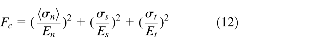
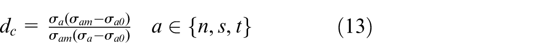
where in Equation (12): Fc is the initiation criterion for damage initiation in the interlaminar interface based on maximum quadratic nominal stress criterion; σn, σs, and σt are the equivalent stresses in the longitudinal, transverse, and thickness directions; dc∈ [0,1] is the damage coefficients correspond to these directions, respectively; σm represents maximum failure stresses; and σ0 represents damage initiation stresses.
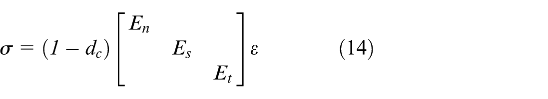
In Equation (13), dc represents damage degradation factors for cohesive elements at interlaminar interface implemented via traction-separation law with bilinear stiffness degradation, and the stress–strain degradation relationship follows Equation (14). The parameters above were validated through Mode I/II fracture tests (ASTM D5528/ASTM D7905/ ASTM D6671) of interlaminar resin bonds.9,10 Implemented in Abaqus/VUMAT subroutines, the mesoscale model utilizes the modulus, strengths, and fracture energies in Table 3.
During the elastic–plastic response, RVE elements obey Equations (9) and (13) with all damage coefficients di = dc = 0. When damage initiation criterion F = 1 in Equations (6)–(8) and (12), the laminate transitions to the damage phase, and stress–strain relationships for each RVE element are computed with all stiffness reduction coefficients in Equations (5) and (13). Finally, element deletion is activated when any damage coefficient di reaches unity, and material progressively transitions to a fully failed state.
Results and discussion
Mechanical properties of single-layer 3D braided composite
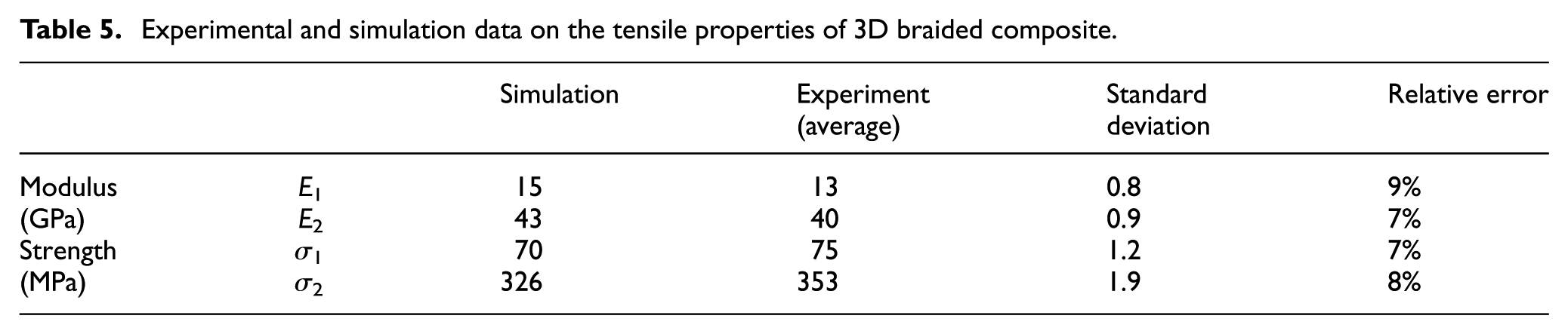
The multiscale mechanical model for single-layer 3D braided composites was validated through experimental-simulation correlation of stress–strain responses and failure mechanisms. To ensure damage prediction accuracy, optimization of 3D braided RVE model was performed utilizing third-party commercial software HyperMesh. Then, the optimized 3D braided FE model was discretized with C3D8R elements using the third-party software TexGen. Mesh sensitivity analysis of the 3D braided RVE FE model (Figure 3e) shows modulus variations of 1–2% for element counts from 5 × 10³ to 20 × 103, confirming convergence. Thus, the element count in the 3D braided RVE model was maintained within the range of 105, achieving high computational accuracy (error <1%) while minimizing resource expenditure. Table 5 reveals pronounced anisotropy, The 3D braided RVE’s longitudinal modulus E1 is 34% of transverse modulus E2; longitudinal strength σ1 is 16% of transverse strength σ2. This originated from 60° fiber orientation where longitudinal fiber volume fraction is significantly lower. The prediction errors of anisotropic mechanical properties of RVE aligned with benchmark studies on refined mesoscale textile models, consistently below 10%: 8%, 33 10%, 23 and <5%. 16 In addition, RVE dimensional validation (Figure 3f) shows 9% (length), 5% (width), and 3% (thickness) errors through statistical averaging of localized topological features.
Experimental and simulation data on the tensile properties of 3D braided composite.
Figures 4(a) and 4(c) reveal quadrilateral-shaped damage zones aligned with the 60° braiding angle, where fiber–matrix shear damage propagates sequentially, inducing interfacial instability and nonlinear load drops. This results from synergistic damage modes (fiber fracture, matrix cracking, interlaminar interface delamination) during stiffness degradation. Figures 4(b) and 4(d) demonstrate constrained deformation in 3D braided composites, exhibiting sequential failure progression: interfacial cracking → frictional sliding → fiber–matrix shear failure. This damage sequence reduces damage tolerance and increases stiffness degradation rate relative to 2D laminated composites, attributable to the lower transverse fiber volume fraction. These limitations can be mitigated by reducing the braiding angle, adding axial yarns, and increasing areal density (braided coverage ratio). This integrated approach enhances structural compactness, thickness, and strength. As demonstrated in Figures 3(a) and 3(c), optimized braiding angle and coverage ratio form tighter interlaminar interlacing yarn architectures to improve anisotropic stiffness. Contrastingly, 2D textiles under similar modifications exhibit inherent defects including wrinkling, ply stacking discontinuity, and fabric relaxation-induced dimensional instability.
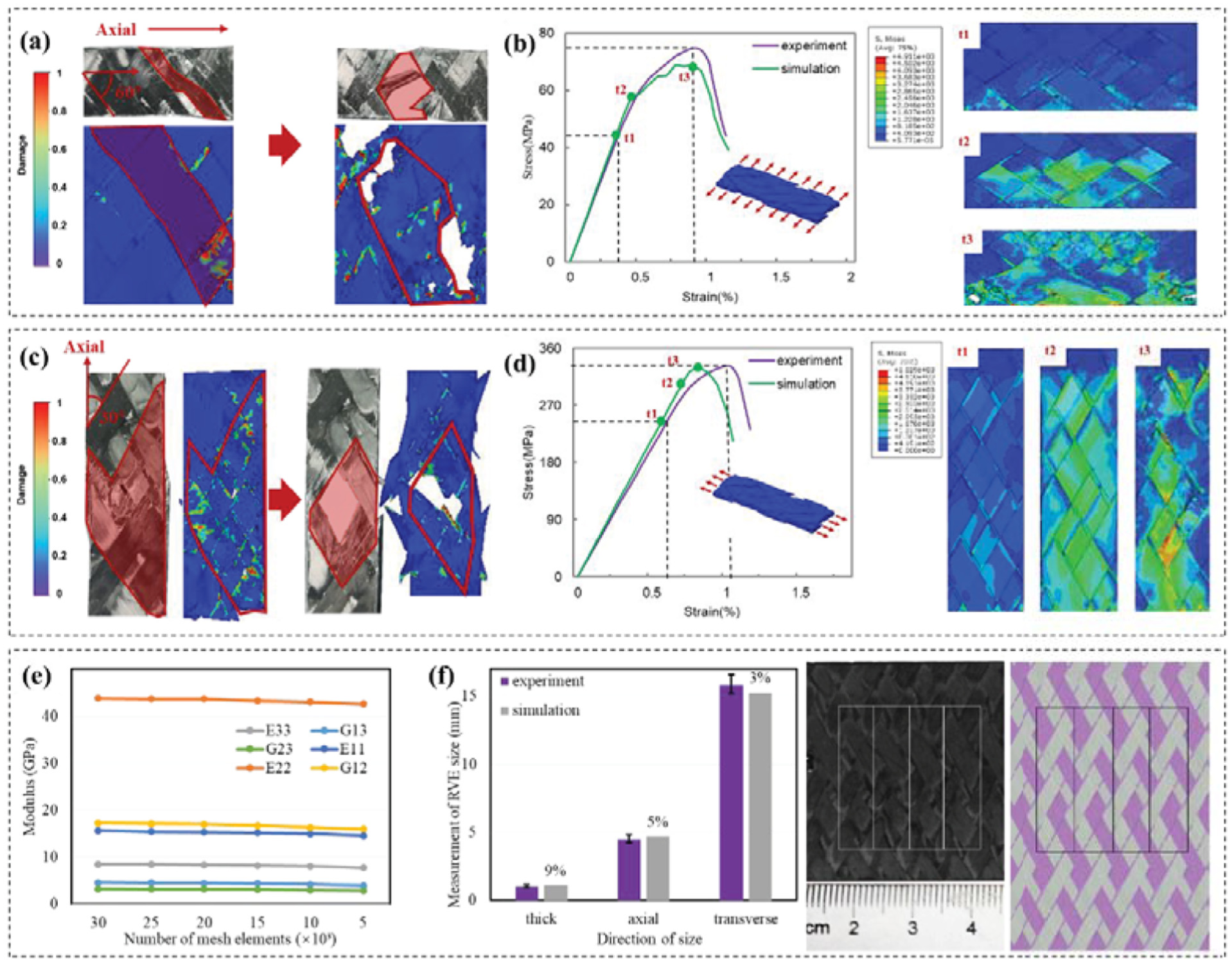
Tensile mechanical properties of single-layer 3D braided structures. (a) Axial tensile cracking and fracture of single-layer 3D braided composite. (b) Stress distribution of cracking and fracture failure of axial tensile. (c) Transverse tensile cracking and fracture. (d) Stress distribution of cracking and fracture failure of transverse tensile. (e) Mesh sensitivity analysis of RVE. (f) RVE size verification.
Comparative analysis of Figures 4(b) and 4(d) reveals that the simulation overestimates maximum elastic strain and elastic deformation load, while underestimating ultimate strength and failure strain relative to experimental data. This discrepancy originates from the use of shared nodes at yarn–resin interfaces in the FE model artificially elevate interfacial stiffness, overestimating elastic response. Meanwhile, the element deletion algorithms prematurely terminate stress transfer during damage progression, leading to underestimated strength predictions. Stress distributions at critical phases (T1, cracking; T2, progressive damage; T3, failure) in the right-hand side of Figures 4(b) and 4(d) reveal the damage progression sequence: matrix cracking initiation, fiber–matrix shear deformation, yarn fracture, and structural collapse. This failure mechanism suggests that optimizing braiding parameters (e.g., reducing braiding angle and adding axial yarns) can enhance anisotropic properties.
Out-of-plane shear properties of 3D braided laminated structure
Model validation and mechanical response analysis
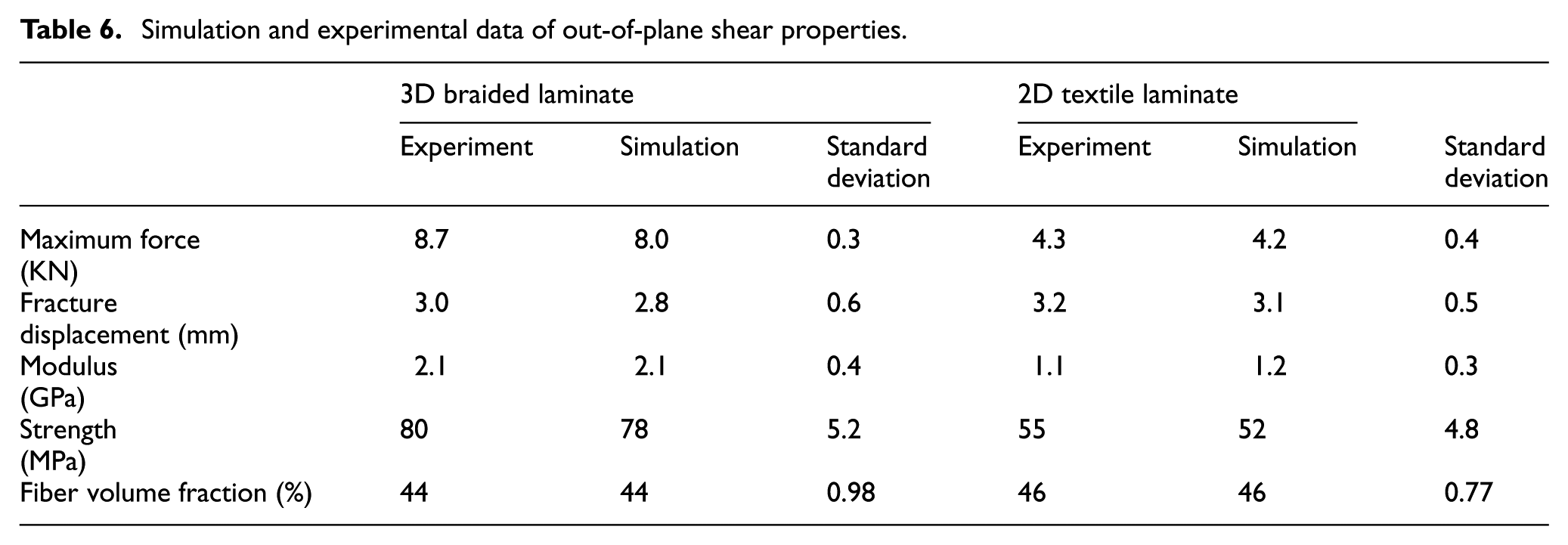
Comparative analysis of load–displacement curves (Table 6 and Figures 5b and 5d) demonstrates that 3D braided laminated composites exhibit 22% higher out-of-plane shear properties than 2D textile counterparts, attributable to Z-yarn reinforcement mechanisms.
Simulation and experimental data of out-of-plane shear properties.
The selection logic for time points t1–t4 in Figures 5(b) and 5(d) is defined by damage criterion thresholds in Figure 5(e):
(1) elastic termination t1 initiated when any element satisfies F =1 in Equations (6)–(8) and (12);
(2) structural fracture onset t2 triggered when all damage criteria reach F = 1 in any element;
(3) peak load t3 corresponds to maximum force during progressive damage;
(4) material failure t4 occurs when damage coefficient d = 1 in Equations (6) and (10), activating element deletion.
Elements are deleted if tensile strain >5% or shear strain >10%. Thus, initial element cracking terminates elastic deformation, whereas first element deletion initiates progressive stiffness degradation. Damage progression diverges significantly: 3D braided laminated composites exhibit gradual failure evolution, whereas 2D textile counterparts undergo abrupt collapse. As evidenced by out-of-plane shear damage modes (Figures 5a and 5c), the 3D braided laminated composites initiated with localized compression damage on the loaded surface and interfacial delamination, progressively developed into hybrid failure modes: compressive crushing (loaded side), tensile fracture (unloaded side), and interlaminar failure. Conversely, 2D textile laminated composites experience extensive interfacial delamination throughout both stages. Despite compressive/tensile fracture of outer plies, mid-layer fibers remain largely intact, exhibiting pronounced warping and protrusion post-unloading due to ply separation. Damage coefficient distributions revealed localized failure in 3D braided laminated composites, damage concentrated in compressive crushing zones on the loaded surface and tensile fracture regions on the unloaded side. Damage propagates thickness-wise from outer surfaces toward the mid-plane, including extensive buckling damage. Divergently, 2D textile laminated composites exhibit extensive damage dispersion, propagating radially from loading zones to free end of specimen during failure progression. During failure progression, the damage front propagates radially, exhibiting rapid diffusion characteristics.
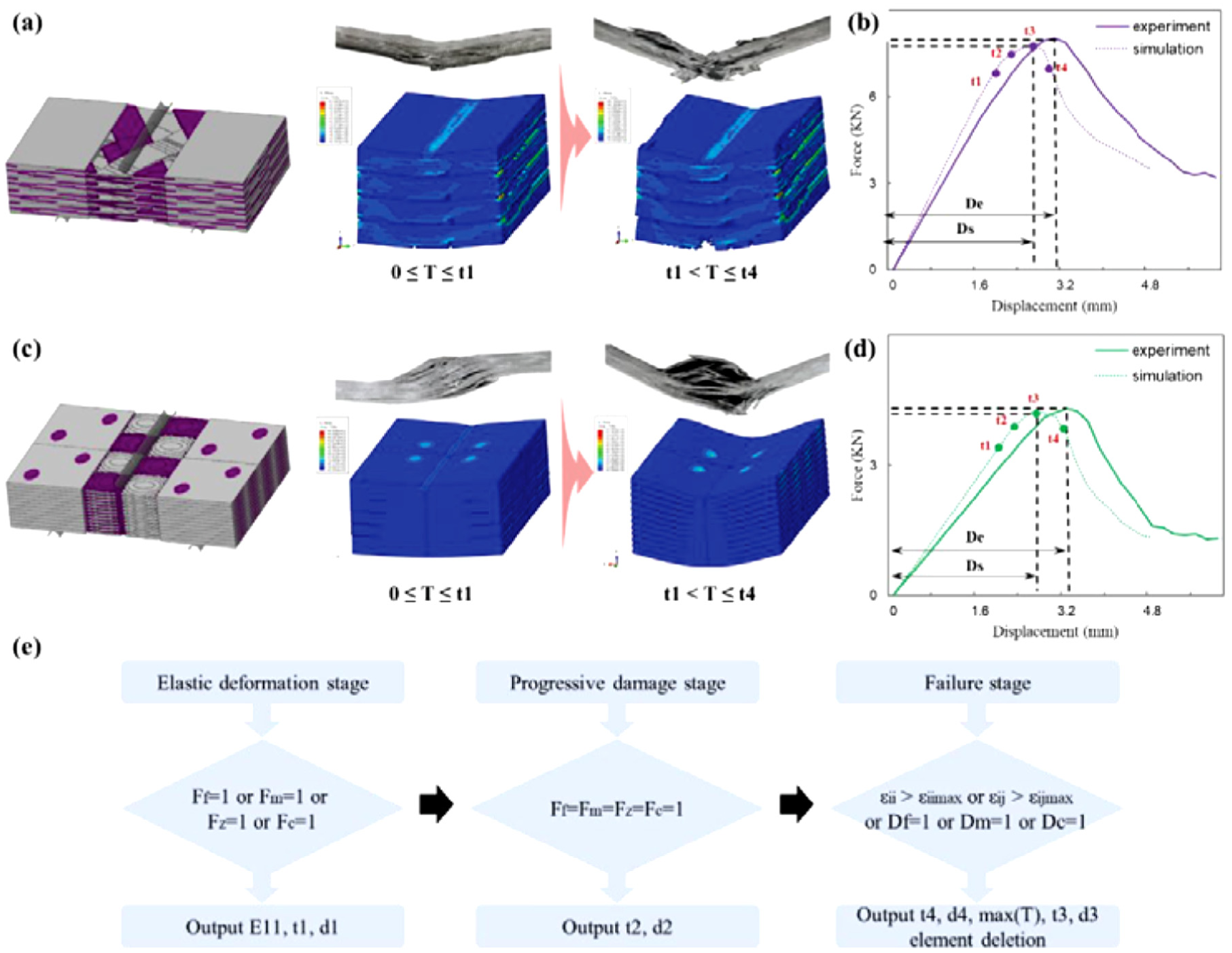
Out-of-plane shear of 3D braided multilayer structures and laminate. (a) Cracking and failure of 3D braided laminated composites. (b) Load–displacement curve of shear process of 3D braided laminated composites. (c) Cracking and failure of 2D textile laminated composites. (d) Load–displacement curve of shear process of 2D textile laminated composites. (e) Program iteration and data output process of Abaqus–VUMAT of out-of-plane shear progressive failure process.
Effect of interlaminar interface on out-of-plane shear failure
In the 3D braided composite mesoscale cross-section shown in Figure 3(a3), its yarns from layers L1–L4 mutually interlock through through-thickness interlacement, forming a tightly integrated yarn architecture that replaces resin-bonded interlaminar interfaces. This structural attribute significantly suppresses interlaminar delamination during out-of-plane loading.
Figure 6 delineates the spatiotemporal evolution of progressive damage within multilayer interlacing interfaces of 3D braided laminated composites. Figure 6(a) exhibits lower fiber fracture in 3D braided laminated composites during t1 to t3. Figure 6(b) exhibits matrix cracking initiation at t1 and progressive damage evolution by t3. A pronounced through-thickness damage gradient emerges, featuring reduced mid-plane matrix damage due to neutral plane proximity, whereas upper-surface damage localizes around loading zones under stress concentrations. Figure 6(c) delineates the cohesive interface damage maintains integrity in compressed zones during t2, yet delamination onset occurs at t3, triggering structural instability. This results from the interlaminar interlacing yarn architecture accommodating greater damage than interlaminar interfaces, thereby retarding interlaminar crack propagation and delaying structural failure. Thess indicates that interlaminar interfacial damage in 3D braided laminated composites initiates subsequent to fiber and matrix failure, exhibiting comparatively limited damage extent contemporaneously.
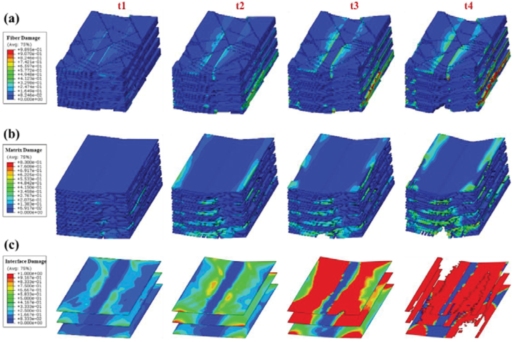
Gradual damage temporal distribution of 3D braided multilayer structure. (a) Time series distribution of fiber damage in yarns. (b) Time series distribution of matrix damage. (c) Time series distribution of interlaminar interface damage.
Figure 7 delineates a marked contrast exists with 2D textile laminated composites, where interlaminar interfacial damage commences at t1, precipitating structural instability by t3, while fiber and matrix damage remains minimal as shown in Figure 7(a) and (b). Following interface separation, the yarn architecture in 2D textile laminated composites disengages from load transfer, forcing out-of-plane loads onto interlaminar interfaces, and predisposing to delamination failure. Consequently, the interlaminar interlacing yarn architecture in 3D braided composites enhances through-thickness load-bearing capacity and effectively mitigates Mode II crack propagation at interlaminar interfaces. This structural mechanism results in superior out-of-plane shear properties and reduced stiffness degradation rates.
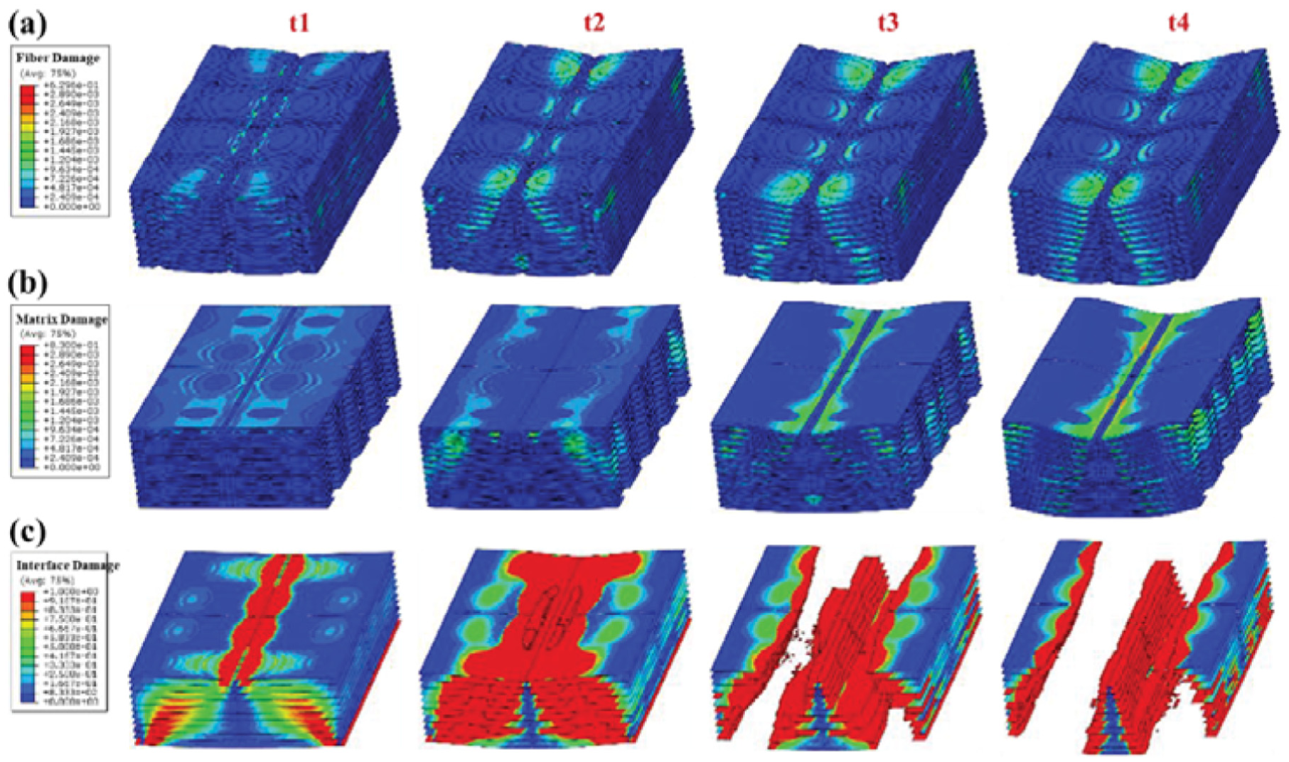
Gradual damage temporal distribution of laminate. (a) Time series distribution of fiber damage in yarns. (b) Time series distribution of matrix damage. (c) Time series distribution of interlaminar interface damage.
Effect of yarn architecture on out-of-plane shear failure
Figure 8 demonstrates cracks distribution in 3D braided and 2D textile laminated composites using digital image analysis of propagation length and density, acquired through 50× optical microscopy at identical resolution. According to ASTM D2344 out-of-plane failure classifications, the 3D braided laminate exhibits buckling-dominated mixed-mode failure. Compression failure on the loaded surface primarily comprises matrix cracking, whereas tensile failure on the nonload side involves fiber fracture and matrix cracking with a certain proportion of interlaminar delamination. This failure mechanism originated from strain rate mismatch between resin and fibers in both loaded and unloaded side of specimen, inducing decohesion and fracture of resin and fibers that ultimately leading to buckling. For 3D braided laminated composites, buckling failure manifests primarily as fiber fracture on the nonload side and matrix cracking on the load side.
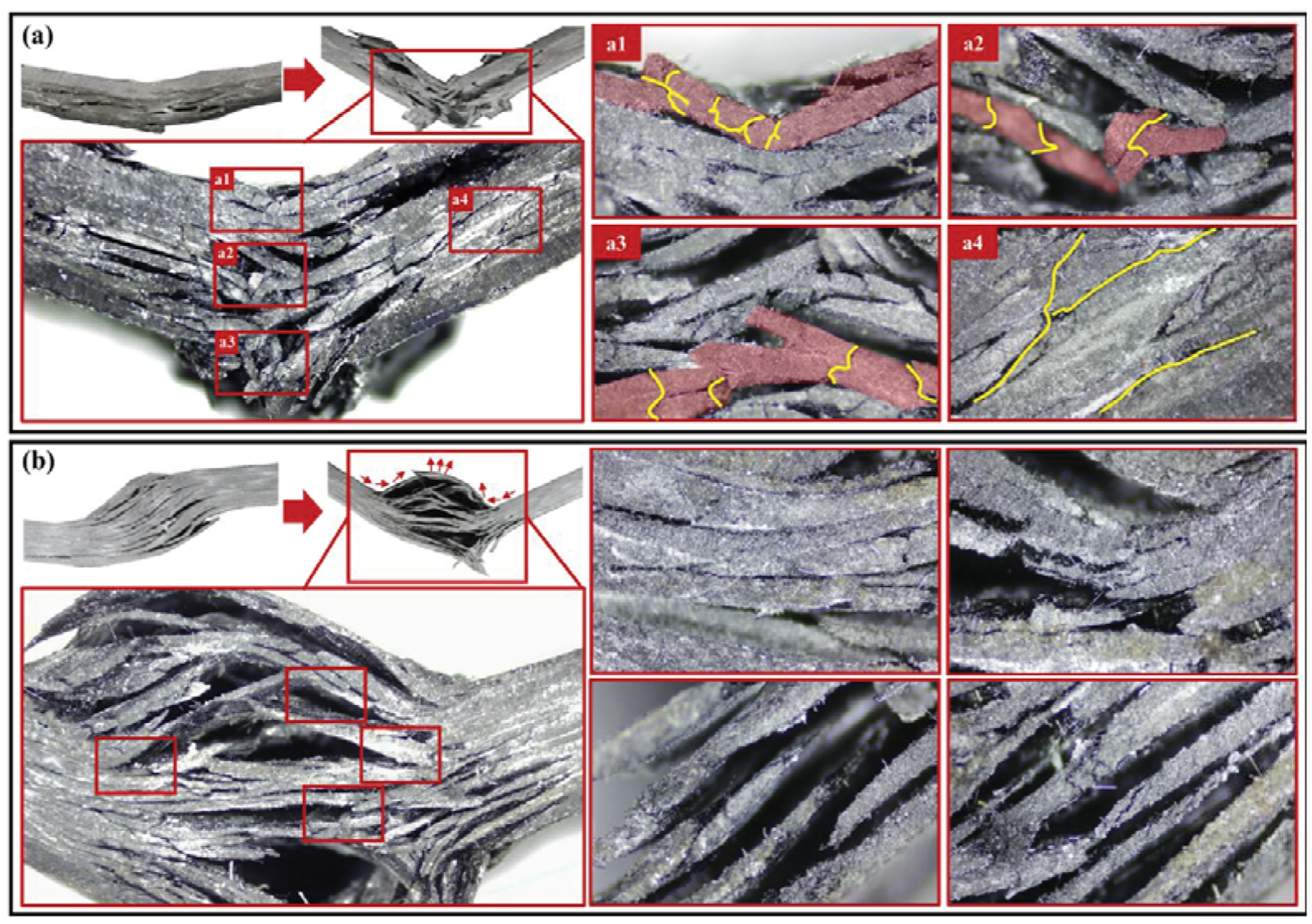
Optical microscopy observation results of out-of-plane shear failure morphology. (a) Flexure and interlaminar shear mixed failure mode of 3D braided laminated composites: (a1) compression damage of loaded side of 3D braided laminated composites; (a2) compression damage in the middle of 3D braided laminated composites; (a3) tensile damage of nonloaded side of 3D braided laminated composites; (a4) delamination of 3D braided laminated composites. (b) Interlaminar shear failure mode of laminate.
In 3D braided composites, cracks propagated symmetrically along the loading axis (maximum length 4–5 mm), contrasting with 2D textile laminated composites exhibiting 7–9 mm crack lengths (Figure 7b). This divergence arises from delamination suppression in 3D braided yarn architectures, where through-thickness yarn constraints restrict crack propagation as shown in Figure 8(a1)–(a4). In 2D textile laminated composites, interfacial delamination dominates failure mechanisms, the resin-dominated interlaminar interfaces exhibits inferior delamination resistance compared to 2D textile yarn architectures, facilitating crack propagation exclusively along interfacial paths without through-thickness fiber-induced constraint mechanisms to inhibit rapid crack advancement. Thereby producing greater crack extension lengths.
The delamination propagation length in 3D braided composites is significantly constrained, primarily attributed to the yarn-interlaced architecture in 3D braided composites, which significantly reduces interfacial continuity across ply interfaces, thereby impeding delamination propagation along continuous interfacial paths. Simultaneously, internal stresses generated by fiber mutual compression during braiding effectively constrain rapid crack propagation along fiber–matrix interfaces. Furthermore, thickness-direction stresses are primarily borne by through-thickness yarn, thereby suppressing Mode II fracture initiation and its propagation tendency at interlaminar interfaces. Consequently, the intricate through-thickness yarn architecture of 3D braided composites absorbs and dissipates fracture energies substantially exceeding interfacial delamination’s fracture energies. During out-of-plane shear failure, 3D braided laminated composites exhibit lower delamination contribution than 2D textile laminated composites, dissipating significantly more fracture energy. Thereby, 3D braided laminated composites achieve enhanced strength and damage tolerance.
Conversely, 2D textile laminated composites predominantly fail through interfacial delamination during out-of-plane shear loading, where energy absorption relies on interfacial mechanisms without fiber-dominated dissipation pathways. Upon delamination initiation at any interlaminar interface, structural instability rapidly propagates. Subsequent interlaminar interfaces sustain the residual fracture energy. Under these conditions, damage localizes predominantly at interlaminar interfaces. Structural instability prevents intact 2D textile yarn architecture from further contributing to out-of-plane load-bearing capacity. This results in post-unloading surface bulging and warping on the loaded side, driven by the interplay between residual stresses from intact fibers and propagating delamination cracks.
In summary, 3D braided laminated composites enable greater fiber participation in damage progression, replacing interlaminar-shear-dominated delamination with buckling-dominated failure mode. This synergistic effect enhances fracture energy absorption, consequently elevating out-of-plane shear properties beyond 2D textile laminated composites.
Effect of stacking layer on out-of-plane shear failure
Although 3D braided composites reduce interlaminar interface density through through-thickness yarn interlacing, residual interfaces persist in thick laminated composites. However, the detrimental effect of interlaminar interface on out-of-plane properties cannot be neglected with increasing laminate thickness and ply count.
As shown in Figure 9(a), 2D textile laminated composites (1–4 ply) exhibit interlaminar-dominant failure modes characterized by stress concentrations at interlaminar interfaces, with peak stress elements localizing precisely at ply boundaries. Conversely, the 3D braided architecture exhibits localized yarn buckling on the loaded surface, with concentrated stress peaks showing limited transverse diffusion. This behavior stems from the interlaminar interlacing yarn architecture, enabling through-thickness load transfer directly via the braided architecture, which prevents global structural instability induced by interlaminar interfacial failure. Simultaneously, the interlaminar interlacing yarn architecture creates complex fiber–matrix interface distributions, which restricts interlaminar damage propagation by through-thickness yarn constraints. Furthermore, the through-thickness yarn architecture contributes to out-of-plane load-bearing capacity of laminates composites. As shown in Figure 9(b), the out-of-plane shear strength of 3D braided laminated composites maintains a consistent 100–200% advantage over 2D textile laminated composites, even as the number of stacking plies (ply) increases from 1 to 4. In Figure 9(c):
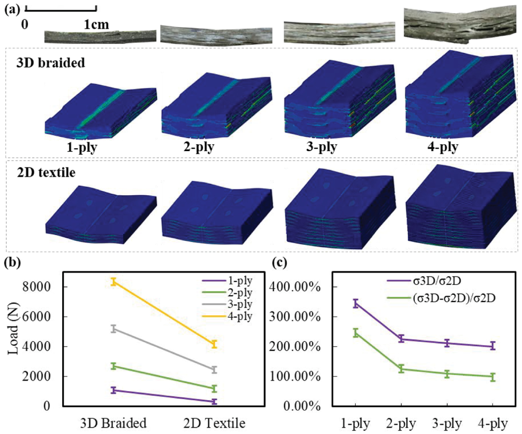
Out-of-plane shear simulation and experiments. (a) Out-of-plane shear failure of 3D braided with different ply. (b) Out-of-plane shear failure loads of laminated structures with different ply. (c) Out-of-plane shear strength ratio of 3D braided and 2D textile.
σ3D is out-of-plane shear strength of 3D braided laminated composites;
σ2D is out-of-plane shear strength of 2D textile laminated composites;
σ3D/σ2D is properties ratio of 3D braided laminated composites and 2D textile laminated composites;
(σ3D–σ2D)/σ2D is the ratio of the net out-of-plane properties enhancement in 3D braided laminated composites to that of 2D textile laminated composites.
As shown in Figure 9(c), (σ3D–σ2D)/σ2D in 1-ply, when the total laminate thickness approximates the single-ply thickness of 3D braided composites, maximum net enhancement of out-of-plane shear properties is achieved (120–200%) over 2D textile laminated composites. Subsequently, the out-of-plane shear enhancement effect in 3D braided composites progressively diminishes with increasing laminate thickness and ply count. This attenuation stems from increasing number of interlaminar interfaces, which induces a higher proportion of interlaminar delamination damage. This demonstrates that substituting 2D textile laminated composites with monolithic 3D braided architectures at equivalent thickness elevates out-of-plane properties by 120–200%.
Effect of braiding angle on out-of-plane shear failure
Figure 10(a1) demonstrates that monolithic 3D braided laminated composites with varying braiding angles exhibit identical characteristic stress distribution patterns at crack initiation. Significant stress concentrations develop at fiber–matrix interfaces within compression zones, with microcrack propagation paths aligning dominantly with yarn orientations. This interfacial stress concentration triggers localized crack initiation within the compression region on the loaded side of laminated composites, culminating in compressive matrix failure. Analogously, the tensile region on the nonloaded side of laminated composites exhibits fiber–matrix debonding, followed by progressive crack propagation leading to tensile failure. Furthermore, Figure 10(a2) reveals relatively dispersed matrix damage, with dominant stress concentrations localized at yarn–matrix interfaces. Conversely, yarn damage initiates within loading nose (Figure 2(a), ASTM D2344) and progressively transitions toward transverse alignment relative to the loading nose as braiding angle of 3D braided laminated composites increases.
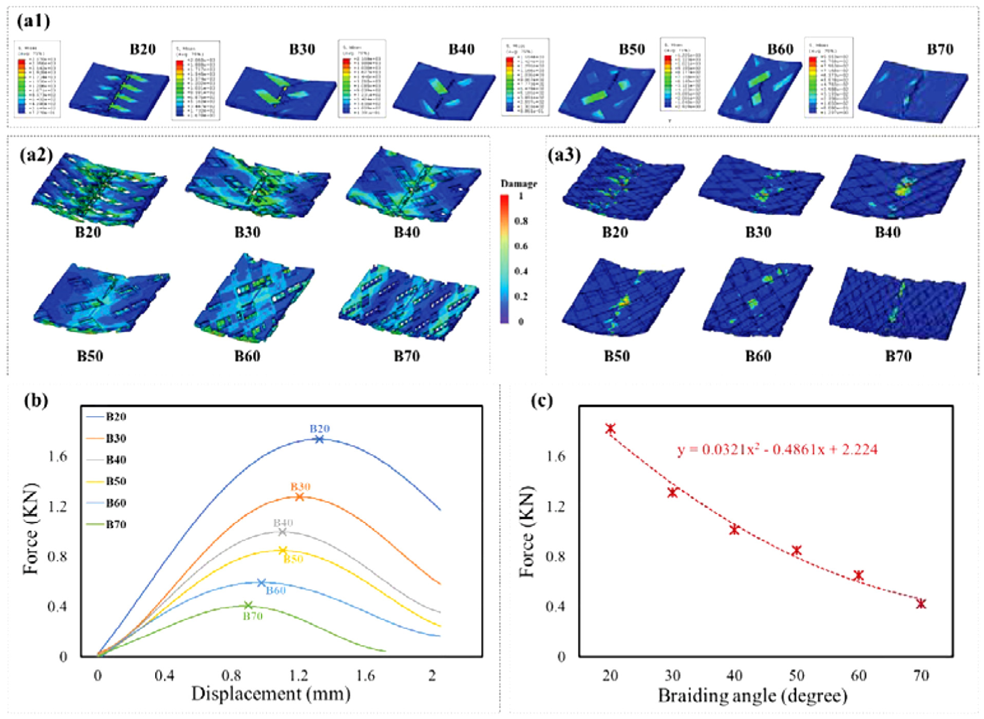
Out-of-plane shear failure analysis of 1-ply 3D braided with different braiding angles: (a1) shear stress distribution corresponding to the maximum load point; (a2) distribution of matrix damage coefficient; (a3) distribution of fiber damage coefficient; (b) load–displacement curve; (c) out-of-plane shear failure loads of 1-ply 3D braided with different braiding angles.
On the one hand, the interlaminar interlaced yarn architecture in 3D braided composites enables effective redistribution of out-of-plane shear stresses. This integrated structure enhances load-bearing stability within the matrix damage phase, facilitating significantly greater fiber participation in out-of-plane load-bearing. On the other hand, damage localization within the yarn architecture of 3D braided composites progressively migrates along the yarn direction with decreasing braiding angle. Specifically, damage concentration transitions from alignment with the loading nose’s width direction toward focus along the fiber orientation within yarns.
Concurrently, Figure 10(b) and (c) demonstrate that decreasing braiding angle progressively increases both the out-of-plane shear stiffness and strength. This enhancement rate becomes more pronounced when the braiding angle falls below 45°. This behavior stems from improved yarn alignment perpendicular to the loading nose direction at smaller braiding angles, thereby enhancing the specimen's longitudinal properties. Critically, under the specific loading conditions and mechanical boundaries of this test, longitudinal properties predominate. In addition, although the thickness of monolithic 3D braided yarn architecture varies slightly with braiding angle, they maintain comparable maximum fracture displacements. This consistency with Figure 5 observations suggests potential thickness dependency governing fracture displacement behavior.
In summary, monolithic 3D braided laminated composites exhibit enhanced out-of-plane shear strength with decreasing braiding angle. This enhancement is primarily governed by the resultant yarn alignment direction.
Significance analysis of the effect of key process parameters
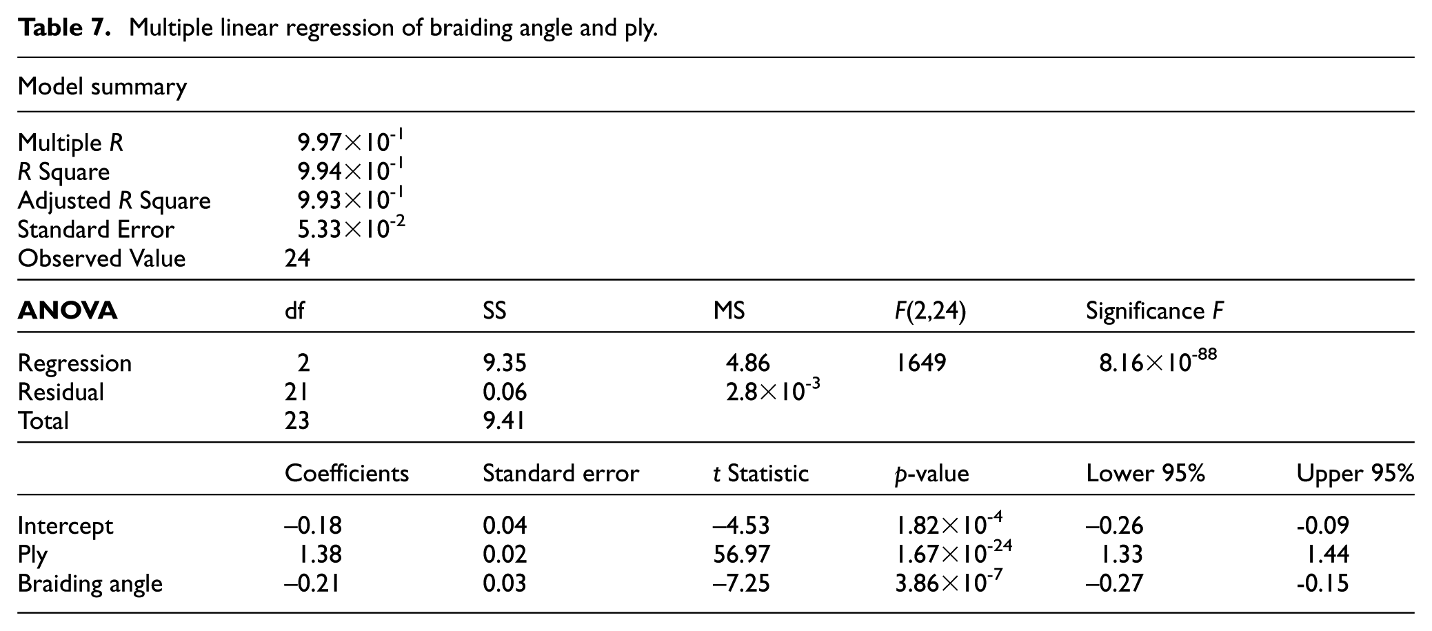
The multiple linear regression (MLR) results in Table 7 indicate: F(2,24) = 1649, p < 0.001, R2 = 9.94 × 10⁻¹, confirming excellent model fit with high confidence. Among the evaluated factors, stacking layer count exerts the dominant influence. This implies that an increase in the number of interlaminar interfaces leads to a pronounced degradation in out-of-plane properties. Consequently, the performance superiority of monolithic 3D braided composites progressively diminishes, as shown in Figures 9(b) and 9(c). Under large stacking layer counts, the out-of-plane properties of monolithic 3D braided laminated composites converges to that of 2D laminated textiles. In such cases, braiding angle exerts only marginal influence on out-of-plane shear properties. Figure 10 analysis indicates that optimizing yarn alignment direction to enhance longitudinal properties yields substantial improvements under out-of-plane shear loading. This occurs due to the high sensitivity of longitudinal properties to these specific mechanical boundary conditions.
Multiple linear regression of braiding angle and ply.
Conclusion
This study has established a refined mesoscopic model of 3D braiding to investigate the coupled effects of parameters including interlaminar interfaces, braiding angles, and ply counts on the out-of-plane shear performance and damage failure processes of 3D braided laminated structures. The combination of braiding process algorithms provides technical reference for mesoscopic modeling of braided composites, while the analysis of multiparameter coupling offers a parametric basis for structural optimization of aerospace composite laminates, especially in improving the delamination resistance of laminates. The main conclusions are as follows.
(1) The mesoscopic model based on braiding process simulation accurately captures different braided architectures and performance, demonstrating good agreement with experimental data in load–displacement behavior and failure mode characterization dominated by buckling.
(2) The interlayer–interlock yarn architecture in 3D braided composite effectively suppresses rapid interlaminar crack propagation, alters crack growth paths, and ultimately leads to a higher proportion of buckling failure. The buckling–delamination mixed failure mode exhibits higher fracture energy dissipation and a slower stiffness degradation rate.
(3) Interlaminar interfaces in 3D braided laminates are influenced by the yarn architecture, which inhibits rapid crack propagation along the interface and delays the onset of complete interlaminar failure.
(4) Increasing the number of stacked layers in 3D braided laminates results in diminishing returns in out-of-plane shear performance improvement. Compared with 2D plain weave laminates of equivalent thickness, single-layer 3D braided composites show maximum enhancement of 120–200%.
(5) Braiding angle exhibits a negative correlation with out-of-plane shear performance in 3D braided composites. Smaller braiding angles correspond to a higher proportion of fibers oriented perpendicular to the shear loading direction, leading to significantly improved out-of-plane shear properties.
Footnotes
Declaration of conflicting interests
The authors declared no potential conflicts of interest with respect to the research, authorship, and/or publication of this article.
Funding
The authors received no financial support for the research, authorship, and/or publication of this article.