
Abstract
In the weaving process of the corner-linked loom, the stability of yarn tension has a significant effect on the quality of the fabric and production efficiency. Focusing on the beam installation structure of the let-off system, the special weaving process of 30-layer corner-linked fabric, and the characteristics of the let-off motion, in this paper we analyze the main factors affecting the warp yarn tension of the corner-linked loom and two control modes for constant warp yarn tension. We demonstrate the theoretical basis of the position mode, presenting parameter derivation calculations. We propose that the direct control method can be used to control the let-off amount per weft, and that the beam diameter estimation method can be used to ensure sufficient let-off amount. The principle of the integral separation proportional–integral–differential (PID) control algorithm and the tension control transfer function model are elaborated, with comparative simulation analyses. Finally, the software and hardware design of the actual warp yarn system and experimental test data analysis are presented. Both simulation and physical experiment results indicate that, in the continuous weaving process, frequent tension fluctuations can be detected by the tension pendulum rod and angle sensor. The combined PID control algorithm can significantly improve the control accuracy and stability of warp yarn tension. The experimental data curve shows that, under step disturbances, the fluctuation amplitude of the tension pendulum rod remains within ±1°, with no overshoot, fully meeting the special weaving requirements of the corner-linked loom.
During the weaving process of the corner-linked loom, it is necessary for the yarn feeding system to provide the weaving area with yarn of relatively stable tension. At this time, the uniformity and accuracy of yarn tension play a crucial role in both the quality of the fabric and production efficiency. If the yarn tension fluctuates excessively, the fabric can exhibit issues, such as uneven elasticity, uneven surface, and irregular patterns, leading to an increase in yarn breakage. For example, excessively high tension might cause yarn breakage, while excessively low tension might affect the shaping effect of the fabric. With the continuous development of three-dimensional weaving technology, composite materials with three-dimensional fabrics as a skeleton are increasingly emerging. 1 This structure, interwoven in three-dimensional space, significantly enhances the resistance of composite materials to impact damage, crack propagation, and stress concentration. In the research and design of loom equipment primarily for carrying three-dimensional fabrics, warp tension control is a core technology in equipment development. Additionally, the tension variation experienced by the periodically moving yarn during weaving is also a key issue worthy of attention, as high-frequency tension fluctuations might cause the yarn to shake or even break during movement. Xie utilized a theory of string vibration to capture the motion state of yarn using a charge-coupled device (CCD) image sensor and recorded the transverse wave phenomenon during yarn movement. By combining image processing technology with yarn motion state images, Xie determined the yarn motion speed and tension. However, this method requires the coordinates of each point on the yarn during the calculation process, making it only suitable for measuring yarn tension on winding machines within a fixed range. Nurwaha and Wang used an image sensor to determine the vibration frequency of moving yarn and calculated the yarn tension through image filtering and edge detection. Chiu and Lu utilized a resistance strain gauge to develop a yarn tension detection device, converting the yarn tension into an electrical signal output from the strain gauge. Using this method, they calibrated the yarn tension against the electrical signal output of the resistance strain gauge, which is highly stable and low cost. However, owing to the influence of environmental and structural factors on the resistance strain gauge, this device cannot detect yarn tension during high-speed motion.
In the relevant research on tension control of weaving equipment, experts and scholars in this field have made notable contributions. Dai et al. proposed an active yarn feeding technology based on the servo motor’s position and speed following changes of the circular loom’s needle cylinder. Although this technology has solved issues, such as yarn breakage and cloth damage, to some extent, the actual effect of yarn tension control is not satisfactory, and this yarn feeding method cannot fully meet the process requirements of variable-tension fabrics created using circular loom weaving. Zheng proposed a dynamic yarn feeding technology for circular looms based on stepper motors, and achieved control over the position and speed of the needle cylinder through a sliding mode controller. However, this yarn feeding method is constrained by the low-speed high-torque characteristics of the stepper motor itself. High speed will reduce the resolution of position control, making it unsuitable for high-speed yarn feeding conditions. Lu and Yang adopted a fuzzy adaptive proportional–integral–differential (PID) algorithm and designed a tension control system using a programmable logic controller (PLC) core controller, but it is limited to the carbon fiber angle-interlock loom in a controller area network (CAN) bus network environment.
To address the issue of constant tension control in the corner-linked loom and effectively enhance the stability of warp tension, in this paper, we first analyze the weaving process and the let-off principle of the corner-linked loom used in three-dimensional quartz-fiber fabrics. Subsequently, a combined PID control algorithm is employed, and the position and speed closed-loop control mode of a servo driver is adopted to solve the problem of tension stability. 2 The design scheme utilizes an AC867 controller as the main control unit and adopts an ethernet for control automation technology (EtherCAT) communication full-servo let-off control system, achieving real-time control of the let-off for 30 sets of warp beam systems. The system is simulated and verified using Simulink in MATLAB, and the control algorithm is experimentally verified on actual on-site weaving equipment. The experimental results and data indicate that the system exhibits significant effects in constant tension control of each layer of warp yarn. The constant tension control strategy for the let-off system of the corner-linked loom proposed in this study holds important theoretical significance and application value. 3
System structure and control principle
Installation structure of warp beam for the let-off system
The multilayer diagonal loom is primarily composed of a large-capacity let-off system, a shedding system, a weft insertion system, a beating system, and a traction system. The quartz-fiber let-off system employs a multibeam multidisc head structure, consisting of 30 sets of independent let-off devices. The installation structure of the beam for one set of the let-off system is shown in Figure 1.
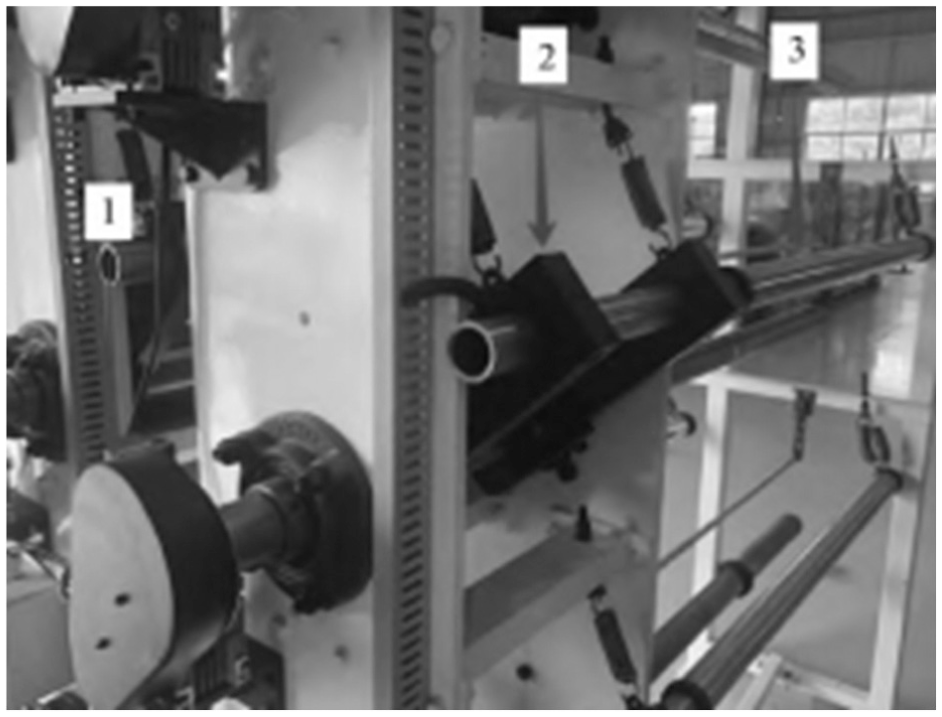
Installation structure of warp beam in let-off system.
As shown in Figure 1, the yarn passes through the let-off component, tension component, and layering component in sequence toward the shedding system. The traction system employs a servo motor-driven reducer to control the lead screw for linear motion. The let-off section adopts a transmission scheme using an SV630N servo motor and a worm gear reducer, with the worm wheel driving the let-off spindle. 4 The tension pendulum rod detects tension angle deviations, calculates the corresponding tension deviations, and stores and compensates for tension changes arising during the shedding and beating-up motions. The main function of the layering component is to facilitate shedding by dividing the warp yarn into 30 layers.
Control principle of constant warp tension
During the weaving process of three-dimensional quartz-fiber fabric, the warp tension is effectively controlled by adjusting the difference between the traction amount of the traction servo motor and the let-off amount of the let-off servo motor. At the same time, a sufficient and uniform let-off amount is required to ensure the weft density and fabric quality of the corner-locked fabric. There are three factors that affect the change in yarn tension.
Traction process. 5 The traction part is driven by a servo motor, combined with a clamping mechanism, to complete the traction motion. Its core impact is to regulate the steady-state tension deviation of the warp yarn. According to actual measurements on the corner interlock loom, when the sampling frequency of the traction system is 100 Hz, the response delay of the servo motor is ≤10 ms, and integral separation PID control is adopted. 6 The tension deviation rate of the warp yarn caused by the traction process can be stably controlled within ±1%, and the tension swing amplitude is ≤0.3°. The influence of the traction process on tension fluctuation is about 12%, mainly affecting the steady-state tension accuracy. 7 When the traction speed deviation exceeds 0.5%, the warp yarn tension will fluctuate synchronously by ±3%, requiring real-time adjustment of the traction roller speed to compensate for the deviation.
Shedding and beating-up process. Changes in the yarn shedding height will lead to a sharp increase in yarn tension. During the beating-up motion, when the reed strikes the weft yarn, the yarn tension gradually increases. When the reed reaches the front dead center position, the yarn tension reaches its maximum value. When the reed returns, the warp tension gradually decreases. As the reed is the primary source of tension fluctuation in the corner interlock loom, it contributes up to 65% to the tension variation. 8 Relevant experimental data indicate that, for every 1 mm increase in yarn opening height, the warp tension increases sharply by 8%–10%. When the opening height is controlled between 8 and 12 mm, the tension fluctuation amplitude is ±8%. During the beating motion, the tension rises from the rated value to its maximum when the reed strikes the weft yarn at the front dead center position, with an increase of up to 30%. As the reed returns, the tension gradually returns to the rated value. The tension fluctuation duration caused by a single beating motion is approximately 0.2 s, and the fluctuation frequency is synchronized with the spindle speed of the loom. 9
Let-off process. The control of the let-off servo motor depends on the reduction of the warp beam diameter, continuously changing the basic let-off amount. The control of the let-off servo motor requires adjustment of the basic let-off amount based on the reduction of the warp beam diameter, which has an impact on tension fluctuation of approximately 23%. Relevant experimental data indicate that, during the process of reducing the warp beam diameter from the initial 400 mm to 150 mm, the let-off resistance increases by 8% for every 50 mm reduction in diameter. If no compensation is made, the warp tension will decrease by 6%–8%. After real-time compensation using the diameter estimation method, the let-off amount error can be controlled within ±0.5%, corresponding to a tension fluctuation amplitude of ≤±5%. 10 For every completed lap of warp yarn let-off, the speed of the let-off motor needs to be adjusted by 0.3%–0.5% to ensure that the let-off amount matches the weaving consumption.
In summary, the effect of the three major factors on tension fluctuation is ranked as follows: beating-up process (65%) > let-off process (23%) > traction process (12%). By combining quantitative analysis with the characteristics of the corner-interlocked loom, a precise quantitative basis can be provided for subsequent control algorithm design, thereby effectively improving the tension control accuracy and ensuring the weaving quality of quartz-fiber corner-interlocked fabrics.
To ensure sufficient warp let-off for each weft, and considering the main factors affecting warp tension, in this paper, we propose a combined PID control scheme for constant tension. By utilizing the position and speed modes of the servo driver, constant control of warp tension is achieved. Based on the special weaving process of angle-interlock fabric, intermittent traction let-off motion is employed, and multiple weft insertion is adopted. 11 When all layers of warp yarn are introduced into the weaving shed, the traction let-off motion begins. The control principle of constant warp tension in this scheme is illustrated schematically in Figure 2.
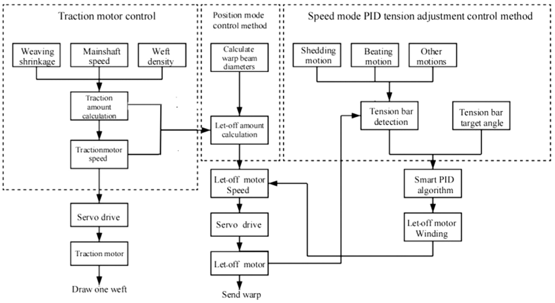
Constant warp tension control.
In Figure 2, the control scheme has the following two modes: when traction movement is detected in the weft, the let-off servo adopts position control mode; when no traction movement is detected in the weft, the let-off servo adopts speed control mode.
Position control mode. The position control mode controls the amount of warp let-off per weft, reducing tension fluctuations during the synchronous movement of traction let-off. The servo driver’s position control mode sets the traction amount per weft based on the loom’s spindle speed and required weft density, treating the traction amount of the traction motor as a fixed value. The servo driver controls the let-off servo motor according to the traction amount per weft, and continuously adjusts the basic let-off amount based on the reduction in the diameter of the warp beam. 7
Speed control mode. For tension fluctuations caused by high-frequency opening motion, beating motion, and other factors, the angle of the tension pendulum rod is first collected. An AC867 controller performs calculations and real-time speed adjustments. The servo motor speed is used to control the take-up and pay-off of the let-off motor, thereby adjusting the angle of the tension pendulum rod to maintain a relatively constant tension state. 12
Theoretical demonstration and parameter analysis of position mode
Derivation and calculation of traction force and rotational speed
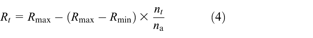
The traction mechanism of the corner-linked loom consists of a servo motor and a reducer driver. As the equipment operates and the let-off motion progresses, the diameter of the warp yarn on the let-off shaft continuously decreases. To ensure the stability of the let-off process, a constant tension needs to be provided during the weaving process. Therefore, the traction amount is used as a reference to control the let-off amount of the let-off motor. The following calculations are used to determine the let-off amount and speed of the let-off motor at the same time.
The traction amount of the corner-linked loom is
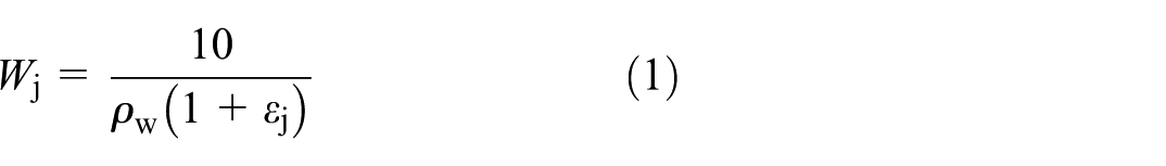
In the formula,
Based on the weft density of the angle-interlock fabric, the controller sends instructions to the traction servo driver. The servo driver uses position control mode to control the motor, setting a speed to pull a specified distance. The amount of traction is equal to the product of the speed of the traction line and the traction time: 13

In the formula,
The rotational speed of the traction motor is
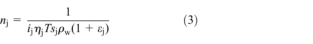
Deducing and calculating the let-off unit
Estimation method for diameter of multiwarp beam and beam disc
In traditional looms, real-time diameter information of warp beams is obtained through such methods as sensor measurement, encoder detection, and image processing. Additionally, a separate compensation let-off program needs to be designed during programming. However, for a corner-draft loom with 30 sets of warp beams, it is necessary to obtain real-time diameter information for each beam separately. Using traditional methods not only increases equipment costs but also occupies additional space resources. In this paper, we propose a diameter estimation algorithm to address the aforementioned issues. This algorithm can directly update the diameter of the warp beam in real time, without relying on additional sensors or equipment support, saving costs and space. 14 This method of calculating the let-off amount by applying the diameter of each warp beam compensates for the deficiency of traditional let-off calculation methods, which require the calculation of additional compensation amounts. By obtaining the warp beam warping parameters, the real-time diameter of the warp beam can be derived as
In the formula,
Calculation of let-off quantity for multiwarp beam and warp disc
The commonly used warp let-off algorithm involves calculating the basic warp feed and setting the warp yarn to be let off at a constant rate. Additionally, based on the weaving shrinkage ratio and changes in warp beam diameter in the three-dimensional weaving process, it is necessary to calculate the warp let-off compensation during the weaving process. In the weaving of three-dimensional quartz-fiber fabrics, owing to the continuous warp feed from the warp beam, the diameter of each warp beam end will continuously decrease. After the warp beam rotates 360°, and one round of warp yarn is let out, the diameter estimation method is first used to calculate the new end diameter of each warp beam, which is then applied in the warp let-off calculation process. Subsequently, the warp let-off amount of each warp servo motor is adjusted to compensate for the insufficient warp caused by the decrease in warp beam diameter.
The core parameters for dynamic warp let-off compensation must be determined by combining the physical properties of quartz fibers (linear density, elastic modulus) with weaving process requirements (weaving shrinkage ratio, weaving speed) to ensure compensation accuracy and dynamic adaptability. 15 The correction coefficient for compensation amount is one of the core parameters. Based on the measured data from the weaving of three-dimensional quartz-fiber fabrics, the basic correction coefficient K0 is set to 0.98, which is used to correct the compensation deviation caused by the estimation error of the warp beam diameter and the fluctuation of the weaving shrinkage ratio. Additionally, a dynamic correction coefficient K1 is introduced, whose value is positively correlated with the current diameter D of the warp beam. The expression is K1 = 0.0012D+ 0.92 (with D ranging from 150 to 400 mm). When the warp beam diameter decreases, K1 decreases simultaneously to avoid tension fluctuations caused by excessive compensation. The final actual compensation amount is equal to the basic compensation amount multiplied by the product of K0 and K1, where the basic compensation amount is calculated from the change in warp beam diameter and the weaving shrinkage ratio. The standard weaving shrinkage ratio for three-dimensional quartz-fiber fabrics is fixed at 1.03. 16
The compensation frequency needs to be coordinated with the warp beam rotation period and weaving speed, taking into account both the timeliness of compensation and system stability. Considering the common rotational speed of 100–150 r/min for the weaving of three-dimensional quartz-fiber fabrics, the let-off compensation frequency is set to 2 Hz, which means that the calculation of the compensation amount and the adjustment of the servo motor parameters are completed every 0.5 s. At the same time, a dynamic frequency correction mechanism is set up. 17 When the warp beam diameter D is less than 200 mm, the compensation frequency is increased to 3 Hz, as the smaller the warp beam diameter, the faster the rate of diameter change, and high-frequency compensation can avoid insufficient let-off. When D is greater than 300 mm, the compensation frequency is reduced to 1.5 Hz to reduce system-redundant calculations and ensure the operational stability of the servo motor. The switching of compensation frequency is triggered by the real-time detection signal of the warp beam diameter, with a response delay of ≤10 ms, ensuring synchronization with the diameter change.
To address the adaptation issue caused by the continuously decreasing diameter of the warp beam, a three-level adaptation strategy of “diameter real-time estimation; compensation amount dynamic iteration; parameter adaptive adjustment” is adopted. Firstly, every time the warp beam rotates 360°, one circle of warp yarn is fed out. Through the diameter estimation method, combined with reference to the current signal of the let-off motor, warp yarn linear density, and tension feedback value, the new bobbin diameter is accurately calculated, with the estimation error controlled within ±1 mm, providing a precise basis for compensation amount calculation. Secondly, based on the newly estimated diameter value, the basic compensation amount and actual compensation amount are recalculated, and the compensation parameters are updated using an iterative algorithm to avoid compensation deviations caused by cumulative diameter errors. 18 After every five diameter estimates, a global calibration of the compensation parameters is performed. Finally, an adaptive adjustment module is introduced to monitor the warp yarn tension fluctuations in real time. When the tension pendulum fluctuation amplitude is ≥0.3°, it is triggered to automatically fine-tune the compensation frequency and correction coefficient. When the warp beam diameter approaches the minimum value of 150 mm, the compensation buffer mechanism is activated to gradually reduce the adjustment amplitude of the compensation amount, avoiding sudden tension changes at the end of the warp beam and ensuring the stability of the let-off amount throughout the weaving process. The compensation strategy always adapts to the dynamic changes in diameter.
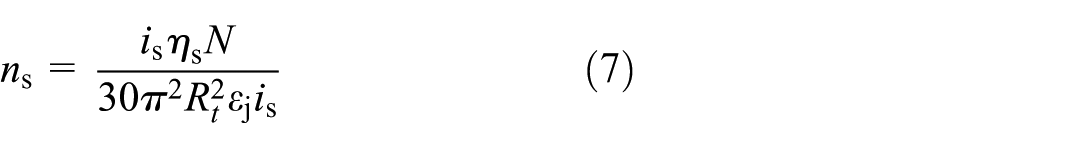
Calculating the let-off amount
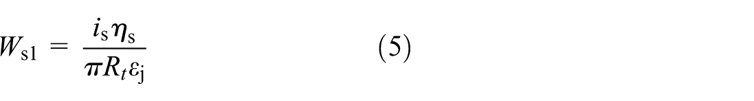
In the formula,
In the weaving process of the corner-linked loom, the controller sends instructions to each warp servo driver to control the speed of the warp beam. The amount of warp per weft is equal to the product of the warp beam speed, radius, and warp time:
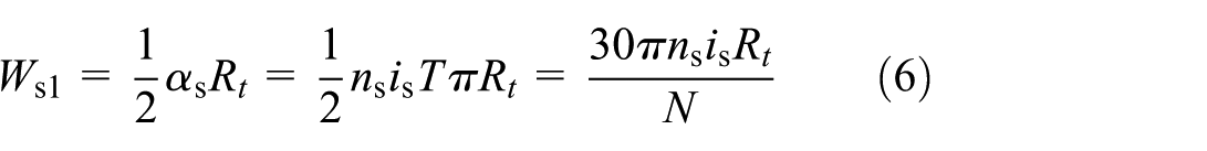
In the formula,
In the weaving process of the corner-linking loom, the controller sends signals to the let-off motor, which can control the rotation angle of the let-off motor directly, thereby controlling the let-off amount of each warp beam. According to equations (5) and (6), the rotational speed of the let-off motor can be obtained as
Integral separation PID control algorithm and its simulation
Integral separation PID algorithm
In the weaving process of the corner-linked loom, to overcome the changes in warp tension caused by motions, such as shed beating, the control system of the corner-linked loom adopts an integral separation PID control algorithm for control. The principle of integral separation PID control is as follows: when the deviation between the swing angle of the warp tension swing rod and the set constant swing angle value is too large, no adjustment will be made for the integral term; in this way, we can avoid affecting the stability of the let-off system, owing to the overshoot effect of the integral. 20 When the measured value of the warp tension swing angle is close to the set constant swing angle value, the effect of the integral term is introduced, which can improve the control accuracy.
Figure 3 is a schematic diagram illustrating the principle of the integral separation PID control algorithm in this design scheme.
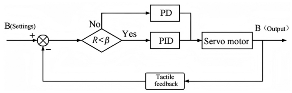
Principle of integral separation PID control algorithm.
In Figure 3, the input signal represents the initial set value of the tension pendulum rod angle, the feedback input signal indicates the detected value of the tension pendulum rod angle, and the output signal is the corrected servo motor pulse value. This forms a closed-loop control system centered around the PID controller. Based on the control requirements of the angle-interlock fabric weaving process and the characteristics of the sensor, warp beam 8 is taken as the research object, and the threshold value is set to β = 3°.
When [γ(k)] > β, the system does not introduce an integral term, and employs PD control via axis 8.
When [γ(k)] ≤β, an integral term is introduced into the control system, and axis 8 adopts a PID control method.
The expression for the integral separation control algorithm PID is
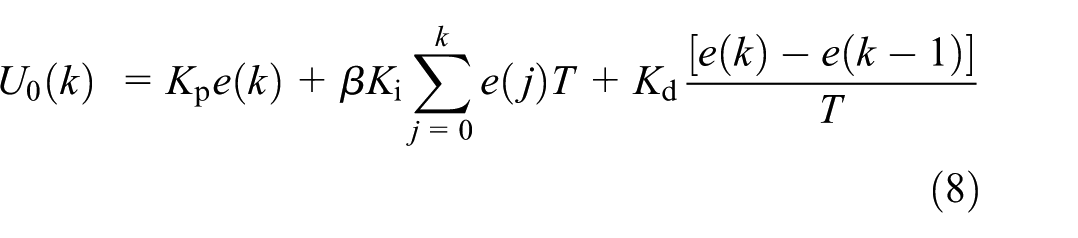
In the formula,
Mathematical model of tension control in speed mode
In speed control mode, the transfer function principle of the tension pendulum mechanism, servo system, and feedback system of this system is as shown schematically in Figure 4.
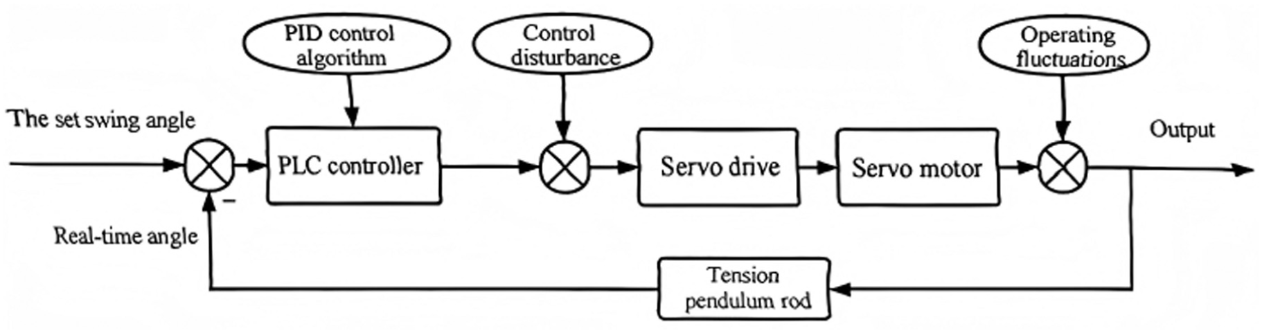
Tension control transfer function.
As shown in Figure 4, a servo motor is employed as the primary actuator. Despite the complex electromagnetic relationship
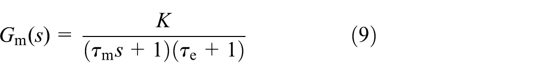
Since the mechanical time constant of an AC servo motor
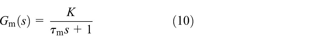
From equation (9), it can be seen that the transfer function of the servo motor can be equivalent to an inertia element. Using an MSR servo motor, and based on testing conducted on the servo motor using debugging software, it was found that the time taken for the motor speed to rise from 0 to 65% of the target value is 0.005 s. Therefore, the electrical time constant of the motor
By setting the parameters of the driver, when the voltage is 1 V and the speed is set to 150 r/min, the gain coefficient K of the motor is
The model of the AC servo motor is
Based on the working principle of the angle sensor, the mathematical model of the warp tension pendulum angle sensor is as a proportional element, representing
Simulation and comparative analysis of PID control algorithm
To verify the effectiveness of the aforementioned integral separation PID algorithm, based on the established mathematical model, a MATLAB simulation comparison between integral separation PID control and PID control can be obtained. By setting the simulation time to 10 s and monitoring the stability of the tension pendulum’s swing angle, it is possible to determine whether the warp tension is in a stable state. In the case of relative tension fluctuations, the simulation step input signal is set to 35, which means that the equilibrium angle of the warp tension pendulum is set to 35°. Simulation outputs for both the traditional PID algorithm and the integral separation PID algorithm are then obtained, and the corresponding warp tension step disturbance response curves are shown in Figure 5.
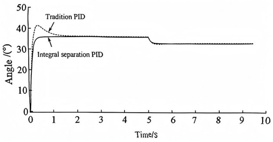
Response curves of warp tension step disturbance.
As can be seen from Figure 5, when the system tension pendulum angle changes from 35° to 32°, the system reaches stability after 0.5 s with the integral separation PID control, and no overshoot phenomenon occurs. However, the traditional PID control method requires a longer time to reach stability and exhibits a significant overshoot phenomenon. Therefore, it can be seen that, when facing changes in the target angle, the integral separation PID control method has more obvious advantages, with a shorter adjustment time and a more stable system performance.
This simulation strictly sets standardized control parameters and operating conditions, and clarifies key simulation configurations. The total simulation duration is set to 10 s, matching the actual weaving short-term dynamic response test conditions. 23 The system sampling time is set to 0.01 s, which balances the response speed of the servo system and the computational load of the controller, conforming to the industrial general standard for textile tension control. The control period is synchronized with the sampling time, using an equal-period real-time control mode with a period value of 0.01 s, to ensure no delay in tension signal acquisition and control command output. The controller parameters use engineering measured optimization values, with conventional PID controller parameters: proportional coefficient, Kp = 3.2; integral coefficient, Ki = 0.15; and derivative coefficient, Kd = 0.28. Based on the conventional PID parameters, the integral separation PID controller adds an integral separation threshold ε = 0.5°. When the tension pendulum rod angle deviation exceeds the threshold, the integral effect is cancelled to eliminate overshoot; when it is less than the threshold, the integral is applied to eliminate steady-state error.
The simulation takes the tension pendulum angle as the core monitoring indicator, with the target stable value set at 2.0. By collecting four indicators in real time, namely, the pendulum angle response curve, overshoot, steady-state error, and adjustment time, the warp tension stability is assessed. 24 The simulation input signal employs a step signal to simulate tension mutation disturbances during weaving, while superimposing random noise with an amplitude of 0.1 to replicate the actual weaving conditions of the angle-interlock loom. By comparing the dynamic response characteristics of the tension pendulum angle under two control algorithms, the advantages of integral separation PID in suppressing tension overshoot, enhancing response speed, and reducing steady-state error can be visually verified.
Design and testing of warp yarn physical system
System hardware design
Owing to the large number of warp yarns and the 30-layer fabric, the let-off system employs 30 independent let-off servo drives. Each let-off subsystem must coordinate with each other let-off subsystem to solve the problem of synchronous let-off of multiple layers of warp yarns. Therefore, an AC867 control unit was selected as the main controller of the let-off system, and a SV630 controller was selected as the servo controller. The main controller and servo controller communicate via an EtherCAT network, and the angle sensor uses RS485 communication, connected to a tension pendulum rod to collect pendulum angle signals. 25
Figure 6 is a hardware structure connection diagram of the actual warp yarn system.
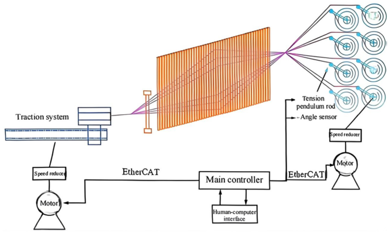
Hardware structure connection diagram of warp yarn physical system.
As shown in Figure 6, the design of the monitoring interface is completed through a touchscreen program and programming is completed through a controller. Since the system has a total of 30 warp beams, if 30 angle sensors are installed, they cannot be directly connected to the main controller. Therefore, the angle sensors are grouped together using four eight-port hubs and connected to the AC867 main control unit via an RS485 bus. After computation, the AC867 main controller determines the winding and unwinding speeds of the servo motors for each warp beam. The experimental setup of the actual warp yarn system is shown in Figure 7.
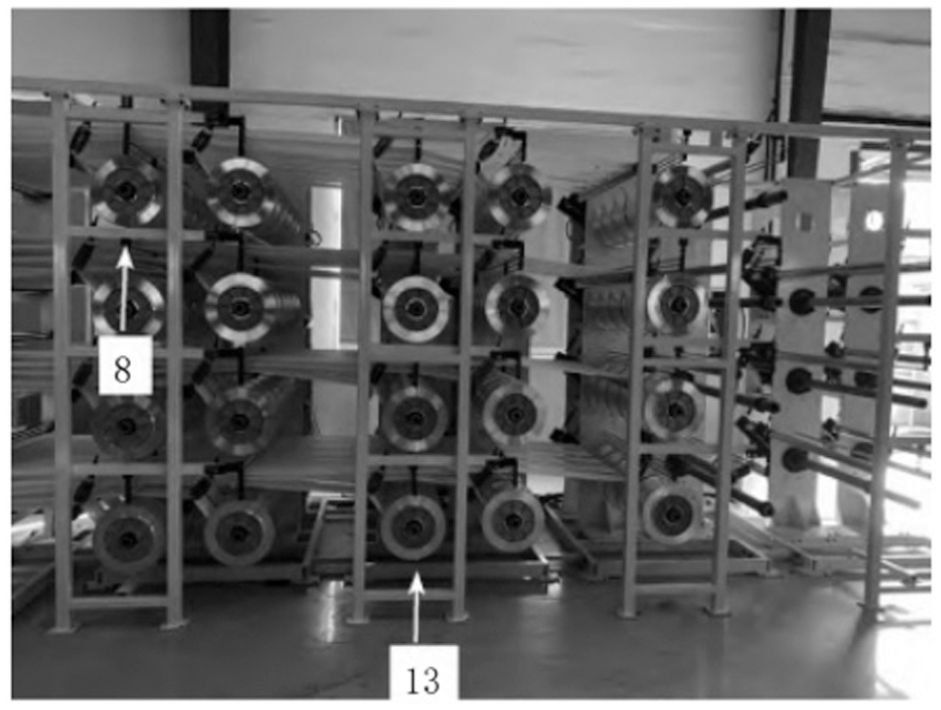
Experimental setup of physical warp yarn system. Number 8 indicates the 8th warp beam, and number 13 indicates the 13th warp beam.
System software design
The programming software InoProShop was installed on a personal computer (PC), EtherCAT master and slave stations were set up, the communication configuration information was downloaded to the PLC, and a software system was built that was completely identical to the actual hardware.
The parameters of each servo driver and motor were configured, the parameters of each input/output (I/O) module were defined, and memory addresses were allocated. The motion control program flow is shown in Figure 8.
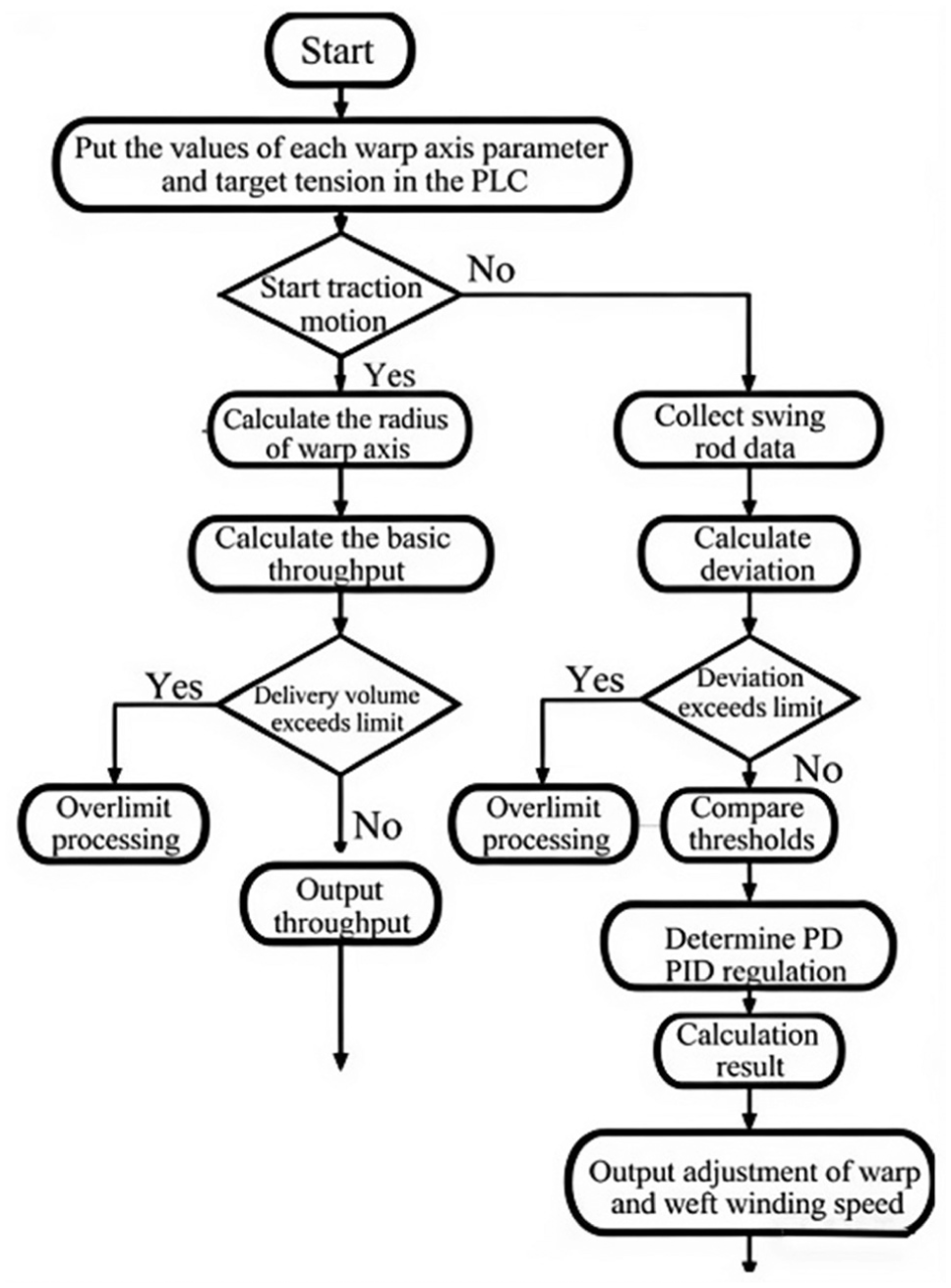
Motion control program.
As shown in Figure 8, the control program includes an automatic compensation subroutine, an integral separation PID subroutine, and a safety protection subroutine. The automatic compensation subroutine is primarily responsible for controlling the basic warp feeding amount, setting the diameter of each warp beam, the number of warping circles, and the warping length, and reading the real-time running circles. The integral separation PID subroutine is mainly responsible for setting the initial parameters for the servo motor’s integral separation PID control, setting the initial input and output PID values, setting threshold determination, and selecting PID parameters to be transmitted to the PID program. When special circumstances are encountered in the warp feeding process, such as excessive changes in the collected inclination sensor data, the safety protection subroutine is triggered to perform emergency shutdown processing. 26
The safety protection subroutine serves as the core guarantee for the stable operation of the system, implementing a fully quantified threshold triggering and standardized shutdown recovery strategy for tilt sensor signals. By combining the weaving conditions of three-dimensional quartz-fiber fabric with the operational characteristics of the angle-interlock loom, two safety triggering thresholds are set: the first-level warning threshold is an instantaneous change rate of the tilt angle of ≥0.5°/100 ms, and the second-level emergency shutdown threshold is when the absolute value of the tilt angle exceeds the rated range of 3.0°–8.0°, or when the tilt angle remains continuously out of limit for 200 ms. If either condition is met, it is determined that the tilt sensor data has undergone excessive changes, and the protection mechanism is immediately triggered.
The execution logic for emergency shutdown is as follows. After the subprogram receives an overrun signal, it cuts off the servo motor drive power within 10 ms; the braking mechanism immediately locks the warp beam rotation and simultaneously triggers an audible and visual alarm. The fault code is locked and uploaded to the host computer to prevent yarn breakage and equipment damage.
For the recovery strategy after a machine stop, a hierarchical restart mode is adopted. After the fault is eliminated, the system automatically detects the position of the warp beam and the state of the yarn tension. It first performs a slow jog reset, driving the warp beam back to the rated swing angle range at a speed of 5% of the rated speed. When the swing angle stabilizes without fluctuation within 1 s, the system automatically loads the preset control parameters, performs a smooth start without impact, and gradually increases the speed to the normal weaving speed. During the recovery process, the inclination data are continuously monitored in real time. If the limit is again exceeded, the machine is immediately stopped for a second time. 27
Analysis of experimental test data
Tension pendulum angle step experiment
The trace function in InoProShop was utilized to collect data on warp tension variations. In the actual weaving process, before determining the target value of the tension pendulum, adjustments need to be made based on the state of the warp yarn to ensure the smooth progress of the continuous weaving process. The purpose of this pendulum angle step experiment is to determine the target pendulum angle for each warp beam and establish the tension on the loom before the formal weaving process. An additional aim of the experiment is to study the effect of changes in the system’s target angle on the performance of the tension system. Therefore, this tension pendulum angle step experiment requires the setting of different target angles through the host computer based on the actual weaving situation. During the experiment, warp beam 8 and warp beam 13 are used as the experimental objects, and the warp beam parameters are set separately, as shown in Table 1.
Parameter settings for warp beam
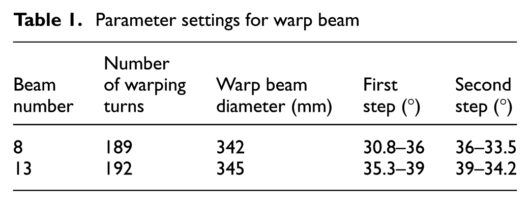
In the preliminary experiment, the spindle speed was set at 20 r/min. In the actual weaving system, the target value of the tension pendulum rod needs to be adjusted in a timely manner according to the warp yarn state during the weaving process, to ensure the quality of the fabric. The tension step disturbance curves for two warp beams are shown in Figure 9.
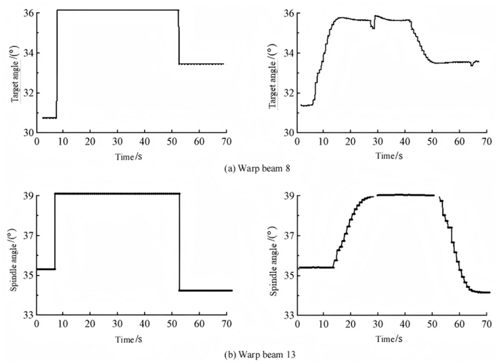
Tension step disturbance curves for two warp beams: (a) warp beam 8; (b) warp beam 13.
As shown in Figure 9, when the system receives the tension value command set by the host computer, it quickly reaches a stable state through combined PID control. Here, we evaluate its dynamic performance based on quantitative indicators: the system’s rise time is ≤0.8 s, the settling time is ≤1.2 s, the steady-state error is controlled within ±0.05°, and the overshoot is 0%. This ensures true zero overshoot and no oscillation, enabling the tension to quickly reach the target state. After the system has been running for 1 s, the control subroutine starts, adjusting the speed according to the target position of the pendulum rod. Under the interference of a step angle, owing to the different sizes of the step angles, the 8th warp beam and the 13th warp beam require 12.0 s and 12.2 s, respectively, to reach a steady state. Although the step angles of warp beam 8 and warp beam 13 are the same, various factors, such as differences in tension on each layer of the machine, cause a slight deviation in the time it takes for the two beams to reach a steady state. Both have steady-state errors that meet the requirement of ≤±0.03°, with an overshoot of 0%. The step angles of the two warp beams are the same, but because of differences in tension on each layer, the tension on the 8th warp beam is 25 N, while that on the 13th warp beam is 28 N. This results in a 0.2 s deviation in the time to reach a steady state, which is within the normal fluctuation range for multiwarp weaving. 28 Therefore, when the tension of each warp yarn reaches the target angle from the preset value, the position of the pendulum rod is basically stable, with no overshoot phenomenon occurring.
Under two step angle disturbances (set at 1.0° and 2.0°, respectively), the dynamic response differences between the warp beams are more pronounced: for the warp beam corresponding to the 1.0° step disturbance, the settling time is 8.9 s, with a steady-state error of ≤±0.04°. For the warp beam corresponding to the 2.0° step disturbance, the settling time is 12.9 s, with a steady-state error of ≤±0.05°, and there is no overshoot phenomenon.
There are significant differences in the time it takes for the system to reach a steady state under different step angles. The larger the step angle, the longer the settling time; this is consistent with the dynamic response law of the control system. When the system reaches a steady state, the fluctuation amplitude of the tension pendulum rod is ≤±0.02°, and the operation is stable with no obvious oscillation.
It can be seen that the tension pendulum rod can quickly respond to step disturbances, with a settling time controlled between 8.9 s and 12.9 s and a steady-state error controlled within ±0.05°, achieving true zero overshoot. This algorithm can quickly adjust the speed of the warp beam and correct the position of the pendulum rod, fully demonstrating the good dynamic performance and control accuracy of the combined PID control algorithm. 29
Warp beam tension experiment based on continuous weaving process
After the tension of the warp yarn on each warp beam and the target angle of the swing rod had been determined, the parameters in the human–machine interface system were set, as shown in Table 2.
Parameter settings for warp beam
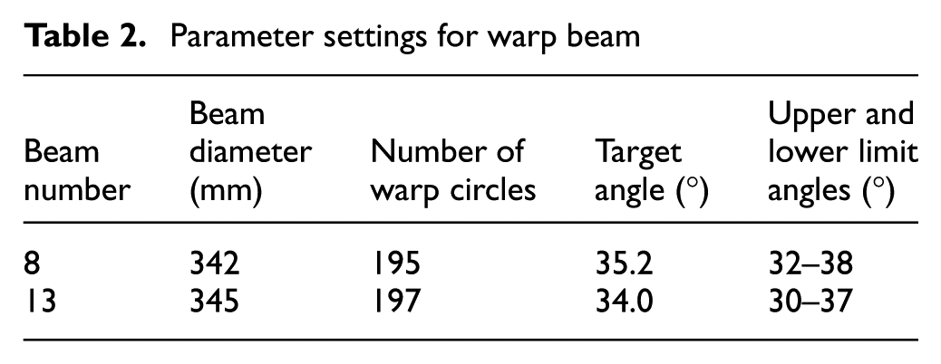
The spindle speed was set to 20 r/min and, within 3 min of the continuous weaving process, the tension curve changes of two warp beams were obtained, as shown in Figure 10.
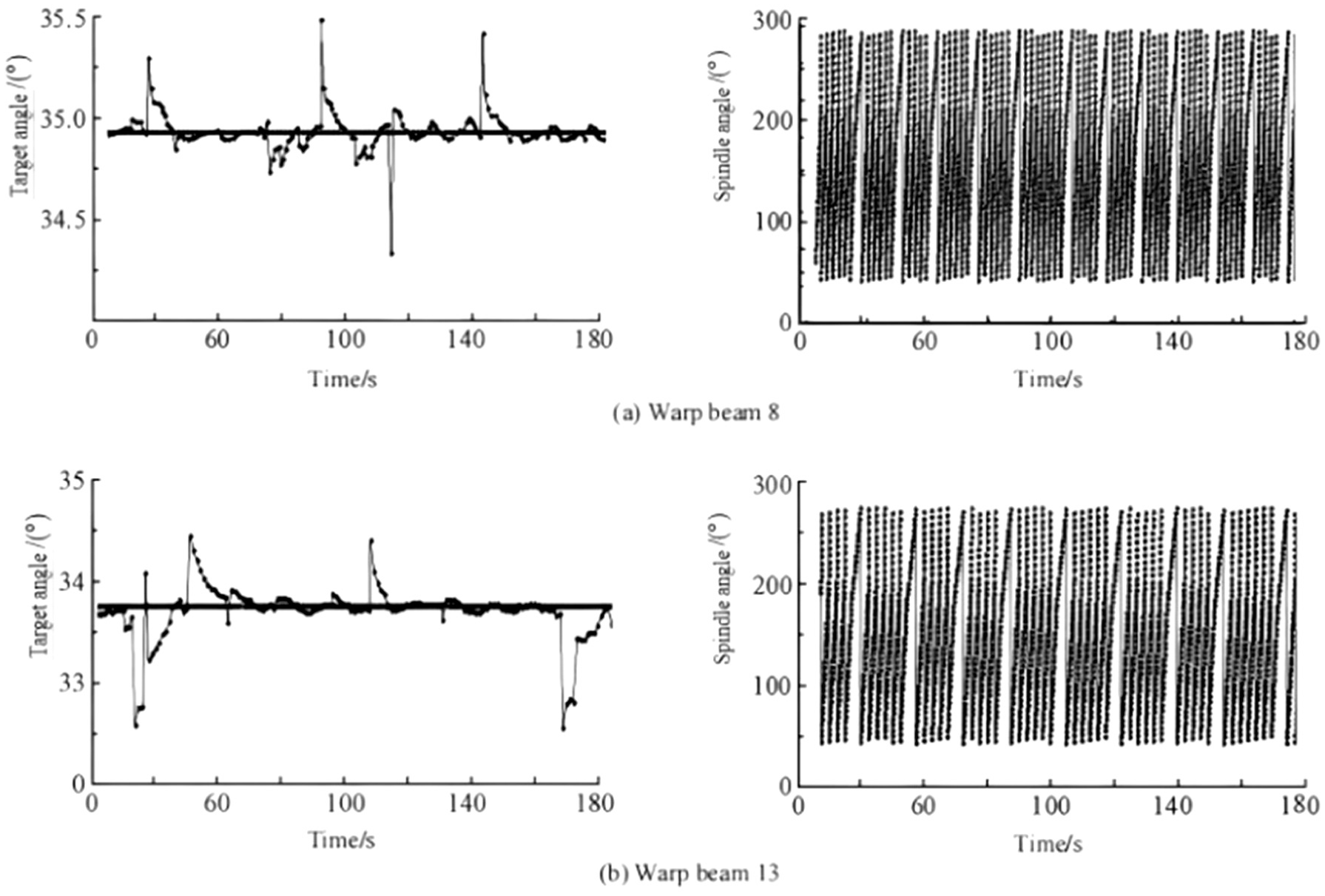
Tension curve variation of two warp beams: (a) warp beam 8; (b) warp beam 13.
As can be seen from Figure 10, during the warp beam weaving process, the fluctuating tension curve of the tension balance pendulum rod exhibits continuous changes. At 30 s and 33 s, the heald frame opening motion has the most frequent effect on tension, showing periodic fluctuations. Owing to the different distances from the heald frame to the warp beam during each weft opening action, the degree of interference from the heald frame’s ascent and descent on the tension pendulum rod varies. The observed maximum interference angle is 0.5°. At 79 s, tension fluctuations caused by the beating motion occur. After this interference, the main controller immediately activates the integral separation PID algorithm in speed mode, quickly adjusting the take-up and let-off response of the warp beam 8 motor, so that each pendulum rod quickly returns to the set position and stabilizes within ±1°. At 89 s, tension fluctuations caused by the warp traction motion occur, and the main controller immediately compensates for the basic warp feed amount through the position mode, stabilizing the tension pendulum rod fluctuations within ±1°. These experiments show that this control algorithm has strong anti-interference capabilities. In the face of various motion inferences, the warp beam can quickly respond, adjust the take-up and let-off, and deliver precise basic warp feed amounts, thus maintaining the dynamic balance state of the tension pendulum rod. Therefore, although there are sometimes tension fluctuations during the warp feed process, the range of tension fluctuations is not large, and does not cause yarn breakage or unclear openings, fully meeting the weaving process requirements for three-dimensional quartz-fiber fabrics. It can be seen that the integral separation PID control algorithm activated by the controller has good control effects on the warp tension of each warp beam.
Conclusion
Addressing the tension fluctuation issue of quartz-fiber angle-interlock fabric in an angle-interlock loom, as reported in this paper, we studied and designed a tension control system based on a combined integral separation PID algorithm. The system, centered on an AC867 controller, analyzes and demonstrates the traction force and automatic compensation of the warp feed amount during the weaving process of multilayer quartz-fiber fabric, thereby ensuring the stability of the warp feed amount. To address the tension fluctuation issues caused by movements, such as shedding, during the weaving process, the system employs a tension pendulum rod combined with an angle sensor, utilizing the PID algorithm to control the motor’s reel-in and reel-out operations and speed, ensuring effective steady-state tension control. Simulation experiments demonstrate that the integral separation PID algorithm exhibits good control performance, fast response speed, small overshoot, and strong robustness, enabling intelligent control of warp tension. Field operation and debugging results show that the system can adjust the warp feed reel-in and reel-out in real time by collecting the warp tension change signals of the warp beam, thus adjusting the tension pendulum rod to a stable position in real time. In the event of interference from other factors during the warp feed process, the servo motor can quickly adjust, and can achieve synchronous and independent control of all warp beams. The warp tension is always stable within the permissible range of ±1°, indicating good tension control performance, fully meeting the precise process requirements for constant tension warp feeding of multilayer fabric in the angle-interlock loom for quartz-fiber angle-interlock fabric.
Despite the good experimental results achieved using the research strategy described in this paper, there are still some limitations in practical applications. For example, the system may be limited by the unique torque characteristics of the motor itself. To achieve a higher rotational speed, the system’s accuracy in position parameters would have to be sacrificed, which would decrease the system’s accuracy in tension control under high-speed yarn feeding conditions. Additionally, in practical operations, yarn tension is often affected by the environment of the conveying path and the structural characteristics of the sensor. The collected yarn tension signals often contain many noise interference signals, which can affect the input accuracy of the tension control system and lead to increased output errors of the control system. 30 Therefore, this study lacks an optimization method that can eliminate the effect of external interference factors on the measurement results of the yarn tension sensor. Further research and experiments are needed to improve existing methods to better address the noise interference problem in yarn tension measurement and enhance the measurement accuracy and stability of yarn tension. For instance, signal feature analysis can be used to classify external interference as periodic signals, singular point signals, high-frequency interference signals, or low-frequency coupled interference signals, and corresponding data processing methods can be adopted. A low-pass filtering algorithm can be added to the control algorithm to filter out high-frequency interference signals in the environment, limit amplitude filtering can be used to remove sudden amplitude increase signals, and low-frequency coupled signals can be smoothed to obtain stable yarn tension.
In addition, considering the significant fluctuations in yarn tension typically observed under high-speed yarn feeding conditions, future improvements in this research should also be focused on yarns with smaller diameters and weaker tensile resistance. Optimization measures should be implemented on the yarn storage disc of the yarn feeder, such as adjusting the yarn winding path, the number of winding turns, and the roughness of the disc's contact surface.
Footnotes
Declaration of conflicting interests
The authors have no conflicts of interest to declare.
Funding
The authors disclosed receipt of the following financial support for the research, authorship, and/or publication of this article: This work was supported in part by the Zhejiang Polytechnic University of Mechanical and Electrical Engineering Key Cultivation Project of Science and Education Integration Incubation Project (grant number A-0271-24-211).