
Abstract
This study investigates the impact of printing orientation on the mechanical properties and surface characteristics of parts produced using VeroWhitePlus RGD835 polymer material in a layer-based Polymer Jetting Technology process. Tensile, hardness, and surface roughness tests were conducted to evaluate the influence of different printing orientations on the properties of the printed samples. The results show that printing orientation significantly affects both the mechanical strength and surface roughness of the parts. Specifically, samples printed in the XZ, YZ, and vertical orientations exhibited 20–30% higher tensile strength and 15–25% greater hardness compared to those printed in XY and other orientations. Surface roughness values varied by up to 10 µm across orientations but did not directly correlate with tensile strength and hardness, suggesting a complex interaction between orientation, layer bonding, and material properties. This anisotropic behavior is attributed to the non-uniform absorption of light energy during the jetting process, which causes varying layer bonding and material density across different regions of the printed parts. Additionally, areas with higher energy absorption, such as the edges of layers, exhibited smoother surfaces and enhanced mechanical properties, while regions with lower energy absorption showed rougher surfaces and reduced strength. Fracture surface analysis revealed brittle fracture characteristics with localized pressures and voids between layers, weakening the material’s ability to withstand deformation. These findings provide valuable insights into the optimization of Polymer Jetting Technology processes, particularly in selecting printing orientations and adjusting process parameters such as light exposure intensity, to improve mechanical performance and surface quality.
Introduction
In today’s rapidly advancing world, the adoption of new technologies and modern manufacturing methods is on the rise.
1
Additive Manufacturing (AM) has emerged as a pivotal tool in the era of Industry 4.0, offering significant reductions in time, cost, and human interaction throughout the product development cycle. AM is fundamentally a layer-by-layer material deposition process used to create objects directly from 3D model data. This technology has gained widespread popularity not only in aeronautics and automotive industries but also in diverse fields such as construction and medical instrumentation.
2
While AM technology continues to evolve, a few specific methods have proven highly successful in producing robust and reliable products.
3
One notable example is the material jetting process, which selectively deposits droplets of build material to fabricate parts.
1
Among these, the PolyJet material jetting system, commercialized by Stratasys,
2
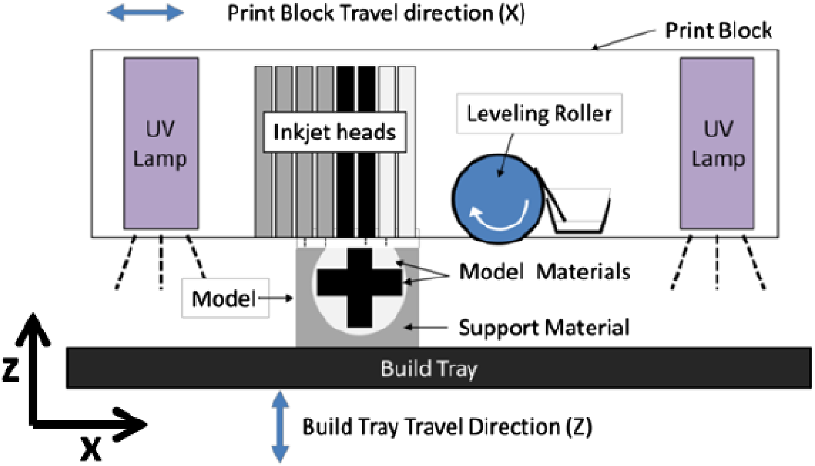
demonstrates exceptional capabilities by enabling the simultaneous deposition of multiple photopolymer resins. In the PolyJet process, inkjet heads within a print block deposit build and support materials drop by drop, which are then smoothed by a roller and cured using a UV lamp (Figure 1). Despite the unique multi-material advantages of processes like PolyJet, further research is required to understand the impact of process variations on the quality of the final product. For instance, the layer-by-layer deposition technique can introduce defects and inconsistencies due to the spreading and bonding of material droplets. To ensure that material-jetted products meet stringent requirements—such as high ultimate tensile strength, isotropic mechanical properties, or long-term durability—variations in material properties must be thoroughly investigated.
3
Scheme of the main elements of the PolyJet 3D printing.
7
Several studies have explored the effects of build parameters on the mechanical properties of 3D-printed parts. For example, Ref. 4 examined the influence of in-plane (X and Y) and out-of-plane (Z) orientations, as well as specimen spacing, on mechanical properties. Their findings revealed that specimens placed closer together on the build tray exhibited superior mechanical properties. In Refs. 5, the authors analyzed the effect of build orientation on tensile properties, manufacturing time, and cost, offering insights into optimal printing configurations for maximizing tensile strength. Similarly, Ref. 6 explored mechanical properties under varying build parameters, concluding that tensile strength improves with a layer thickness of 0.1 mm, although mechanical anisotropy persists due to denser structures forming at part edges. These findings underscore the inherent anisotropic nature of layer-by-layer fabrication processes, often leading to variations in mechanical performance depending on the build direction. Photopolymers used in PolyJet printing also exhibit viscoelastic behavior, 7 and build orientation significantly influences their mechanical characteristics. For example, vertical build-ups benefit from support material shielding during the curing process, although increased layers and intersections can weaken the structure. 8 Process parameters such as spacing and print head movement also impact material deposition quality and uniformity, potentially leading to defects and inconsistencies. 9 Ref. 10 highlighted the influence of build orientation on mechanical properties like tensile strength and impact resistance. Additionally, previous studies have explored methods to enhance mechanical performance by optimizing build parameters and material properties.
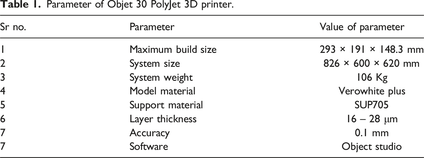
While significant progress has been made in understanding various aspects of PolyJet technology, limited research has specifically focused on practical applications for users, particularly in terms of how build orientation influences mechanical properties. In this study, an Objet 30 PolyJet printer was employed to fabricate parts using VeroWhitePlus RGD835 as the model material and SUP705 as the support material. The process involves precise layer-by-layer deposition of fluid photopolymers through multiple nozzles, followed by UV curing. This enables high accuracy (100–300 microns) and smooth surface finishes, which vary with part geometry, orientation, and size.
11
Figure 2 outlines the main elements of the PolyJet 3D printing process. The printer utilizes separate containers for model and support materials, maintained under controlled temperature and moisture conditions. The support material, FullCure 705, provides stability during fabrication and is easily removed post-printing using a high-pressure water jet, particularly for complex geometries. ASTM D638 Type 1 Siemens NX model.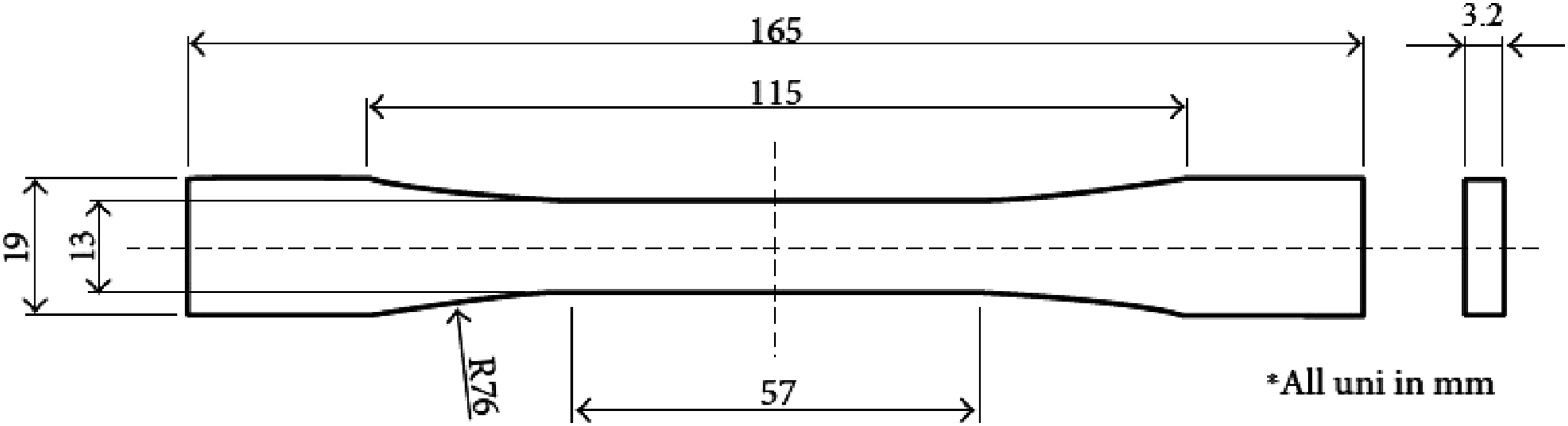
Previous studies have investigated various aspects of PolyJet technology, often focusing on the influence of process parameters and build orientation. For instance, Kim and Oh 12 analyzed dimensional accuracy, surface roughness, and strength using the Eden 500 printer, highlighting the role of build orientation on part quality. Udroiu and Mihail 13 examined the effect of printing direction on surface finish through experiments with square samples, providing insights into orientation-related variations in surface properties. Vieira et al. 14 studied the mechanical and optical properties of PolyJet materials in relation to post-cure treatments, while Brajlih et al. 15 proposed a computational method for optimizing scale factor values in PolyJet rapid prototyping. More recently, Barclift and Williams 16 explored the relationship between build orientation and tensile strength, focusing on elastic modulus and part spacing using a full factorial design. Despite these efforts, there remains a gap in research regarding the direct relationship between build orientation and the mechanical properties of PolyJet parts, particularly in terms of surface roughness and strength.
This article aims to expand engineers’ understanding of how part orientation impacts the mechanical properties of components produced using PolyJet technology. By systematically studying the effects of build orientation on surface roughness and mechanical strength, this work addresses a critical knowledge gap in additive manufacturing research. While prior studies have examined individual factors such as tensile strength, surface finish, and dimensional accuracy, the unique contribution of this research lies in its integrated approach, which systematically investigates the combined effects of build orientation on both surface roughness and mechanical properties. The findings will offer actionable insights for optimizing design and manufacturing processes, ultimately paving the way for the production of high-quality parts with superior performance and reliability.
Materials and methods
Parameter of Objet 30 PolyJet 3D printer.
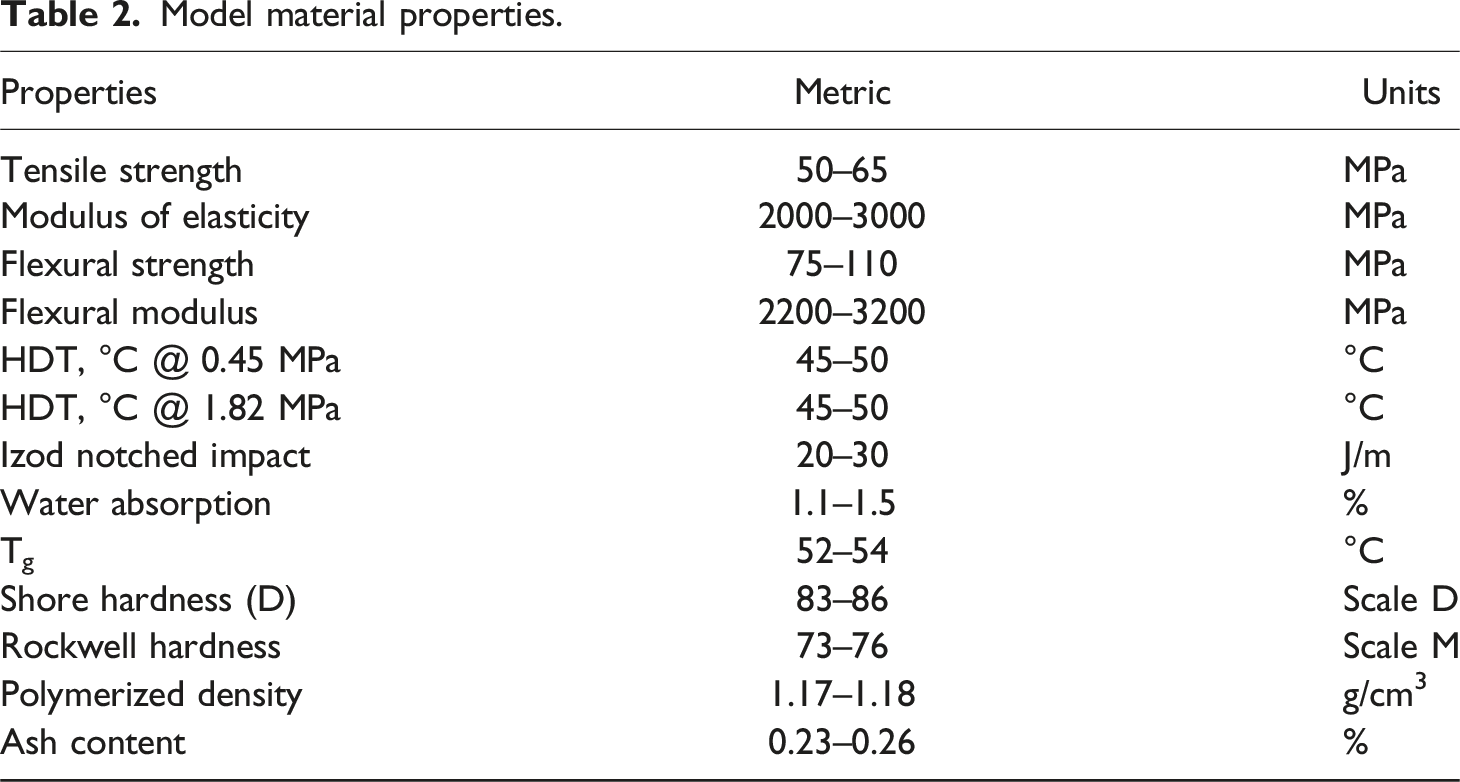
Model material properties.
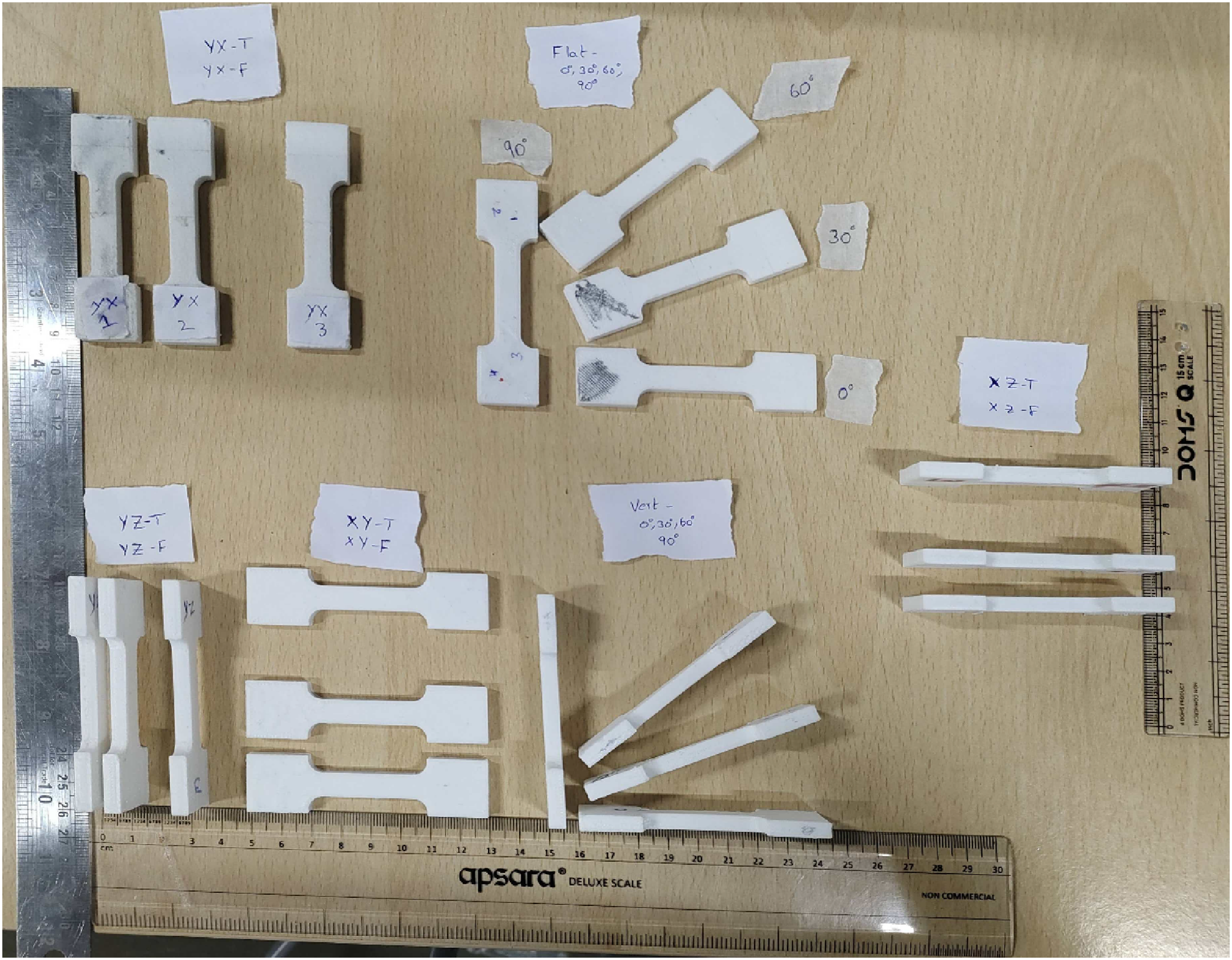
This study investigates the effect of varying parameters such as the spacing between the specimens, models, and parts, as well as changes in the orientation of the model, on the mechanical strength of the specimens. In this section, the positions and orientations of the build parts are defined. Two types of part spacing between the specimens were considered: “Tight (T)” and “Far (F)”. These spacings represent the placement of the specimens on the printing table. The longitudinal and transverse positioning of the specimens were set in the XY plane, which corresponds to the tray table, while the Z-direction indicates the feed direction. The specimens were oriented at four distinct angles: 0°, 30°, 60°, and 90° (Figure 3). Additionally, the parts were oriented in both the XY-plane (denoted as “flat”) and in the Z-direction (denoted as “Vert”), as shown in Figure 4. All test specimens were printed with a nominal thickness of 3.2 mm using PolyJet technology, which allows modification of two key parameters: position, orientation, and finish. Position and orientation of specimen. Specimens fabricated with 3D Polyjet printer.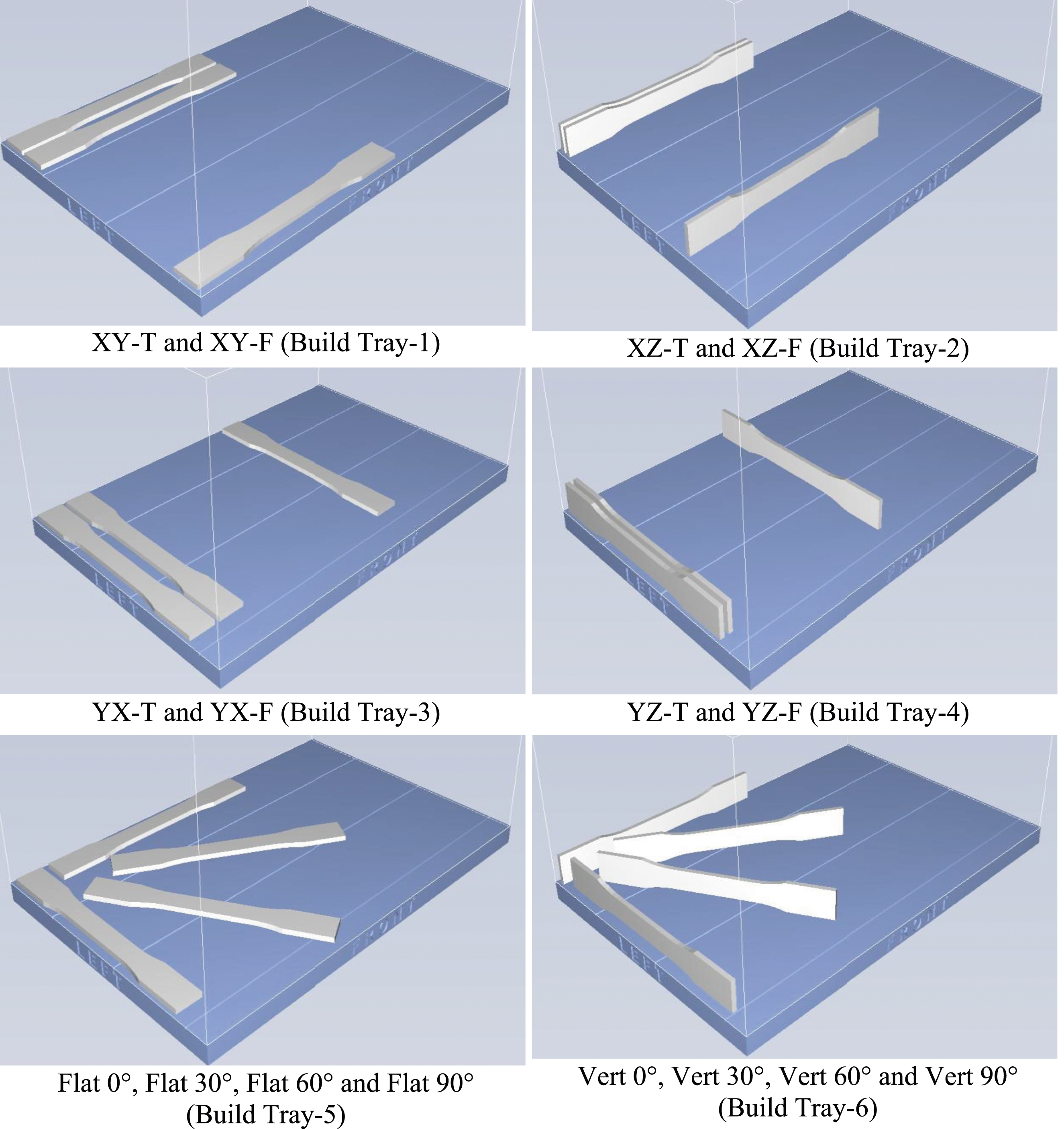
The printer allowed for two user-specific finish options: (i) Glossy print, where the top and other vertical faces are devoid of support material, and (ii) Matte print, where the exposed faces of the specimen are covered with support material. The remaining configuration settings were set to the default values specified by the manufacturer.
For the purpose of analysis, eight combinations of positions and part orientations were considered. These combinations include: (a) Longitudinal (X) and transverse (Y) positioning: XY Glossy, XY-R, XY-T, XY-F (b) Longitudinal (Y) and transverse (X) positioning: YX-R, YX-T, YX-F (c) Longitudinal (X) and transverse (Z) positioning: XZ-R, XZ-T, XZ-F (d) Longitudinal (Y) and transverse (Z) positioning: YZ-R, YZ-T, YZ-F (e) XY-plane orientation: flat 0°, flat 30°, flat 60°, flat 90° (f) Z-Vertical orientation: Vertical 0°, Vertical 30°, Vertical 60°, Vertical 90°.
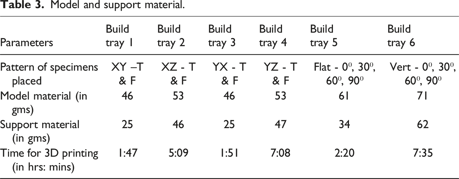
Model and support material.
Tensile properties.
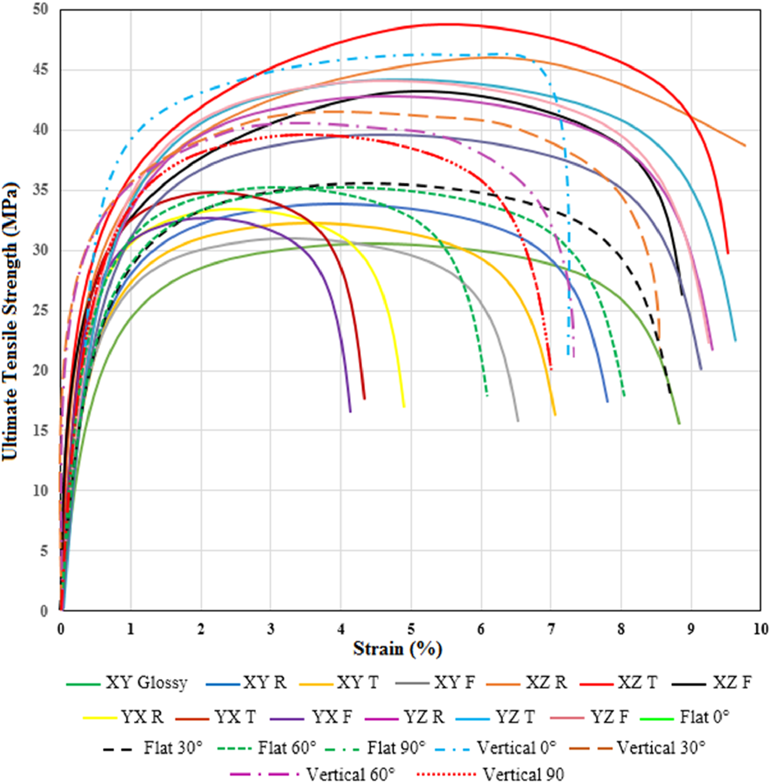
Stress-strain curves of 3D-printed parts for different printing orientations.
Three distinct testing methods were employed to investigate the impact of the orientation of printed parts on their mechanical properties. Uniaxial tensile tests were conducted until failure using a Universal Tensile Testing Machine (UTM) at room temperature, following the ASTM D638 standard. For each condition, three specimens were tested to ensure data reliability. The ultimate tensile strength, peak load, and strain at peak load were measured, providing insights into the overall mechanical performance. Standard deviation values were calculated and included in the tables to reflect data variability and enhance reproducibility. Surface roughness was assessed on the printing-oriented side of the specimens before testing to understand the influence of print orientation and surface integrity on tensile behavior. Surface hardness testing was performed using a Rockwell Hardness Testing Machine on the HRC scale with a 1/14″ ball indenter, with measurements taken on the printing-oriented side of the specimens prior to tensile testing to evaluate their resistance to deformation. Additionally, the fracture surfaces of the tensile specimens were examined using Scanning Electron Microscopy (SEM) to analyze the failure mechanisms and microstructural characteristics. This analysis provided valuable information about fracture morphology, including features indicative of brittle or ductile failure and interlayer delamination.
Results
Tensile properties
The tensile tests were performed at room temperature using a Universal Tensile Testing Machine in accordance with the ASTM D638 standard. The tests were conducted on each specimen at a loading rate of 0.8 mm/sec until specimen rupture occurred. The percentage area reduction was determined to be 97.596%, calculated from an initial sample area of 41.6 mm2. The stress-strain curves for all tested specimens are presented in Figure 5. These curves provide a comprehensive depiction of the tensile behavior of specimens fabricated in different orientations and with varying spacings. It is observed that specimens printed in vertical orientations (e.g., XZ and YZ) exhibit higher ultimate tensile strength (UTS) compared to those printed in the flat (XY) orientation. Among the vertical specimens, those with tighter spacing (T) demonstrate significantly improved tensile properties compared to those with far spacing (F). The distinct patterns in the stress-strain curves are consistent with the anisotropic behavior reported in the literature,
17
emphasizing the influence of printing orientation and spacing on mechanical performance. The curves further highlight that vertical 0° specimens possess the highest UTS, indicating superior load-bearing capacity. Conversely, flat 60° specimens display the lowest UTS, which aligns with their weaker alignment relative to the tensile load direction. These findings are in agreement with previous studies,17–19 which reported similar trends in anisotropy and mechanical properties for 3D-printed and additively manufactured components. In addition to the stress-strain curves, a standard deviation graph (Figure 6) has been included to quantify the variability in UTS values across different specimens. The graph illustrates that specimens printed with tight spacing exhibit lower standard deviations compared to those with far spacing, signifying more consistent mechanical properties. Furthermore, specimens aligned closer to the X-axis direction (e.g., vertical 0°) show minimal variation in UTS, whereas those oriented toward the Y-axis (e.g., flat 60°) demonstrate higher variability. This underscores the critical role of orientation and layer alignment in determining both the reliability and reproducibility of mechanical performance. Mean values with standard deviation for UTS across printing orientations.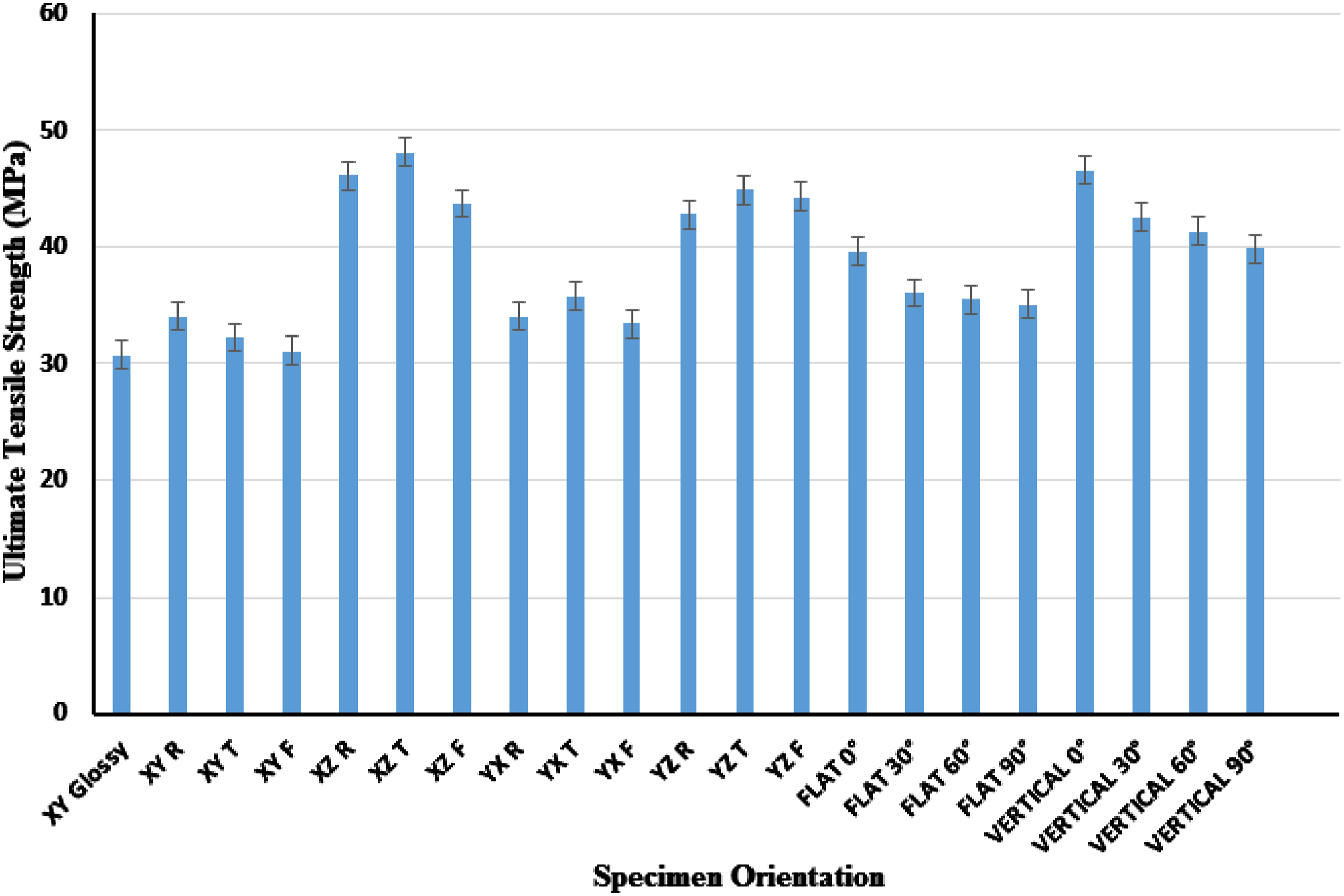
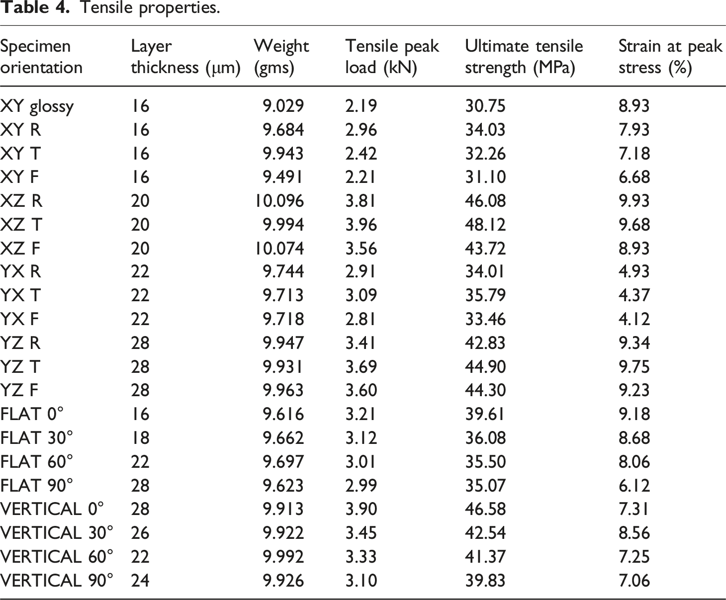
The standard deviation analysis adds robustness to the findings by providing statistical validation. These insights offer valuable guidance for optimizing printing parameters to achieve consistent and superior tensile properties in additively manufactured components. The results indicate that UTS is higher for specimens printed in the XZ and YZ orientations compared to those printed in the XY orientation. Among the vertical specimens, the UTS is the highest for XZ-T specimens and the lowest for YZ-F specimens. Similarly, specimens printed with T exhibit higher UTS values compared to those printed with F. Among the flat specimens, orientations closer to the X-axis display higher UTS compared to those oriented toward the Y-axis. Notably, vertical 0° specimens demonstrate the maximum tensile strength, whereas flat 60° specimens exhibit the minimum tensile strength. This behavior aligns with findings from previous studies. For example, Ref. 17 investigated anisotropy in laser-sintering-fabricated polymer components and found that components manufactured along the X-axis orientation exhibited higher tensile strength compared to those fabricated along the Y-axis, while the Z-axis orientation showed the lowest strength.
This behavior can be partially attributed to the heat distribution across the part bed in laser sintering (SLS), as the fixed heating units in SLS systems often result in non-uniform thermal gradients, which significantly influence mechanical properties and shrinkage. Similarly, Ref. 18 demonstrated that tensile strength could vary by up to 16% depending on the orientation of laser-sintered nylon-12 samples. Ref. 19 further corroborated these findings, highlighting that building orientation and layer thickness significantly influence the material properties of 3D-printed components. In processes such as Fused Deposition Modeling or Fused Filament Fabrication, where the part bed is unheated, anisotropic properties are more prominently influenced by part orientation during fabrication. The enhanced mechanical properties observed in the vertical orientation can be attributed to the number of layers aligned with the tensile force direction. For instance, the Vertical 0° orientation with 28 layers exhibited the highest tensile strength of 46.58 MPa, underscoring the advantage of effective stress distribution along the build direction. Similarly, the XZ T specimens with 20 layers showed a tensile strength of 48.12 MPa, highlighting the influence of tighter spacing on improving load-bearing capacity. In contrast, the YZ F orientation with 28 layers displayed a relatively lower tensile strength of 44.30 MPa, indicating that while the number of layers is a factor, the alignment and spacing significantly contribute to the tensile properties. The Vertical 30° specimens with 26 layers had a tensile strength of 42.54 MPa, further emphasizing the role of orientation in influencing mechanical performance.
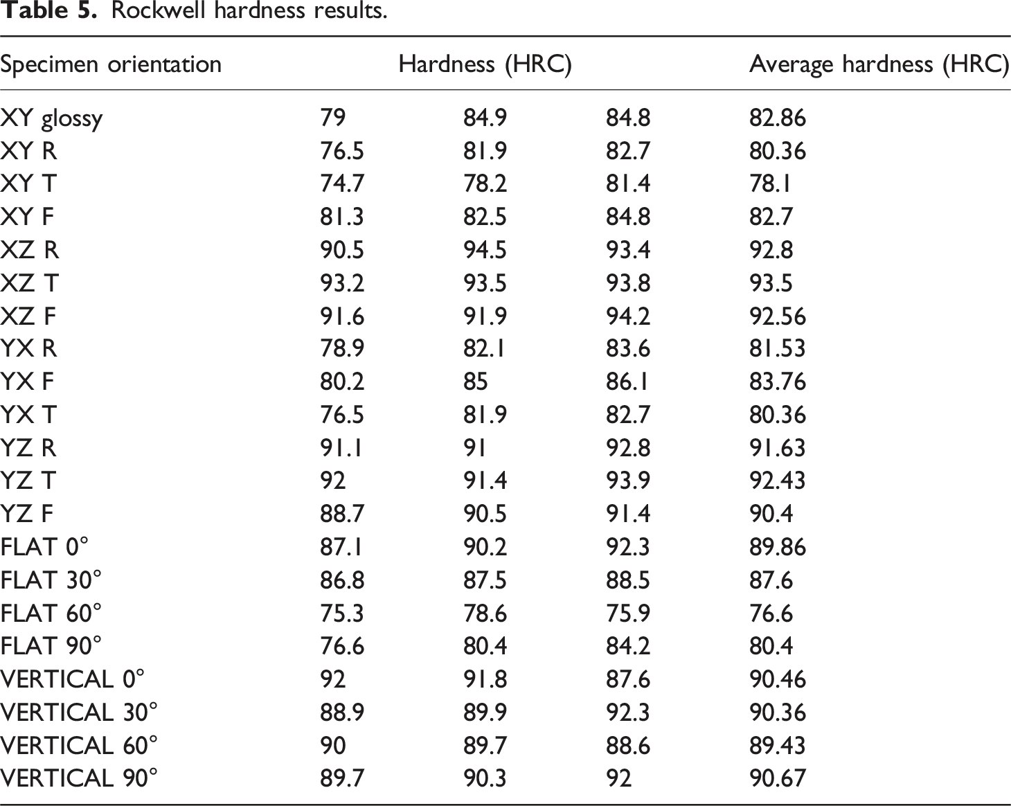
Hardness
Rockwell hardness results.
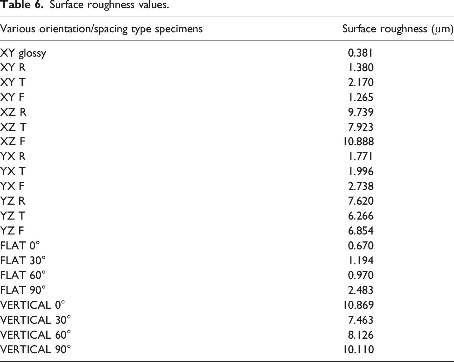
Surface roughness
Surface roughness values.
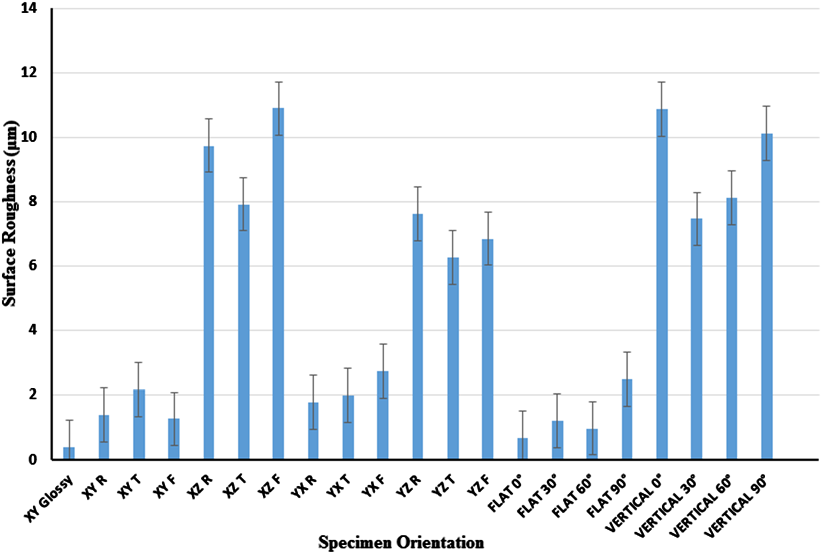
Surface roughness mean values with standard deviation for different printing orientations.
Fracture surface
The SEM photographs of fractured component surfaces after testing are shown in Figure 8. The photographs show micrographs of the fracture surfaces of the tested components during the experiments. The photographs were taken from the fracture regions of the material in the test outcome particularly the portions showing fracture angles and plastic deformation. The presence of air gaps between the layers is the reason for the weak bonding between them. SEM images of fracture surfaces of the XZ T, YZ T and vertical 0° test samples.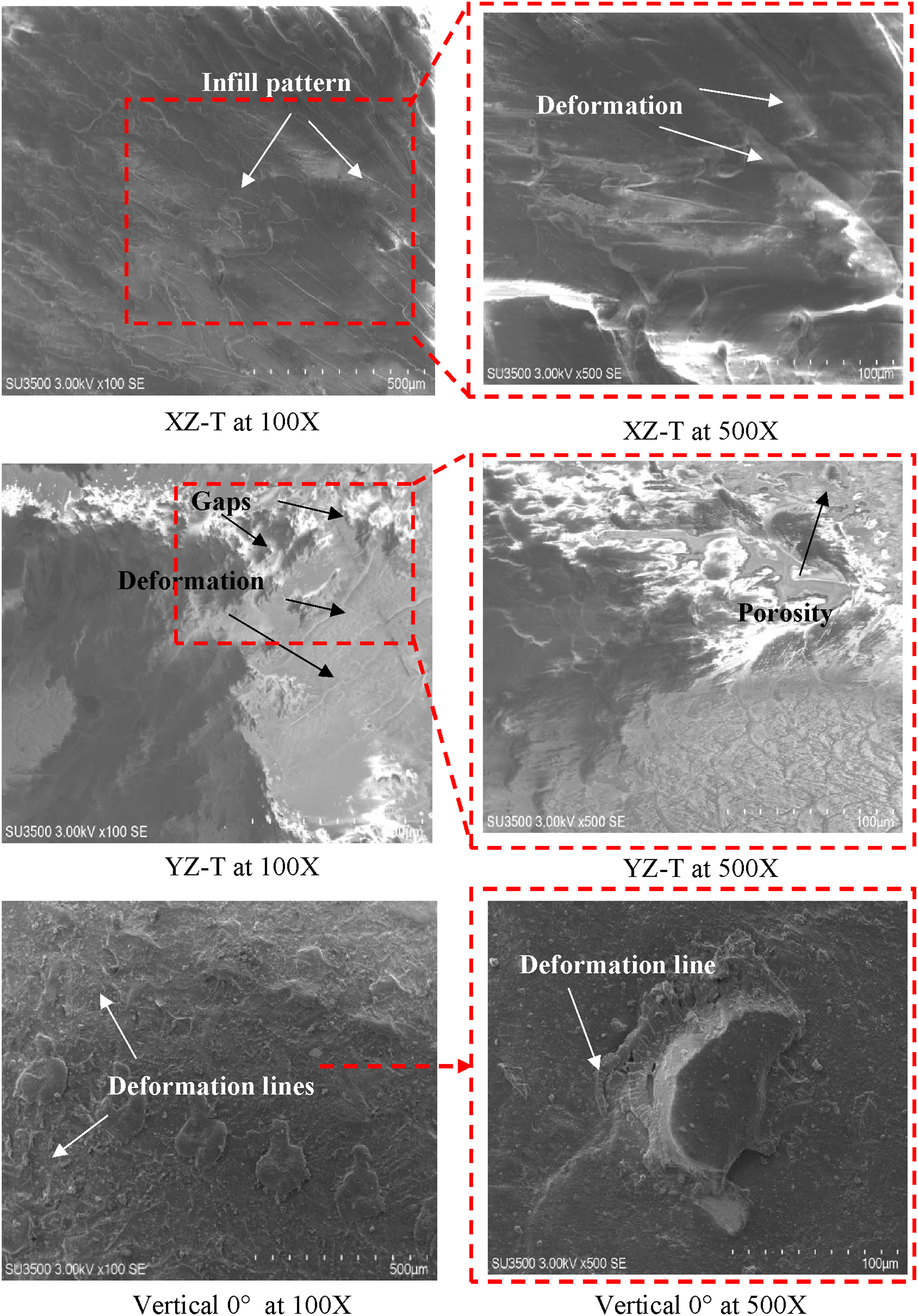
The presence of these voids induces residual strains by influencing the distribution of heat throughout the manufacturing process. 22 These gaps are known to result in the creation of different tensile values. However, the presence of a porous structure and significant spaces on the surface diminished the test samples’ ability to withstand deformation. 23 The cross-sectional view of the fracture test components clearly shows the distinct parallel layers formed during the PolyJet manufacturing process. The presence of surface porosity and significant gaps enhances the ability of the test items to undergo deformation. Consequently, the pores formed due to the 3D printing process inside the rigid plastic reduced the strength of the tested samples. The results were better, but they appeared like they were made from rigid plastic because the material loses some of its strength during production. The SEM photographs reveal that the PolyJet 3D-printed material exhibits brittle fracture behaviour, resulting in a rough surface texture. This signifies the presence of several localized pressures that arise during the fracture process. 24
Discussion
The anisotropic mechanical characteristics observed in specimens produced via PolyJet technology can largely be attributed to the bonding between layers, which influences their overall strength and behavior. This anisotropy arises due to the varied bonding mechanisms at play in different orientations during the printing process. A critical factor in this analysis is the assumption that the bonding stress between layers remains constant for each orientation, though this assumption does not account for variations observed across different sample orientations. For the X orientation, where the applied force is perpendicular to the layer surface, the analysis is straightforward and aligns with expected results. 25 However, when considering other orientations, such as the XY or YX directions, the same bonding stress assumption does not fully explain the mechanical behavior. The surface-to-surface connection between layers remains consistent across all orientations, suggesting that the applied force should theoretically be the same. 26 However, this fails to consider the unique challenges presented by the geometry of the printed layers and the manner in which energy is distributed during the printing process.
PolyJet printing is typically known for its uniform energy distribution across the part bed via moving light exposure. However, challenges arise due to the interaction between this uniform light exposure and the geometry of the printed layers. The UV light’s intensity varies across different regions of each layer, particularly at the edges, which results in non-uniform energy absorption.
10
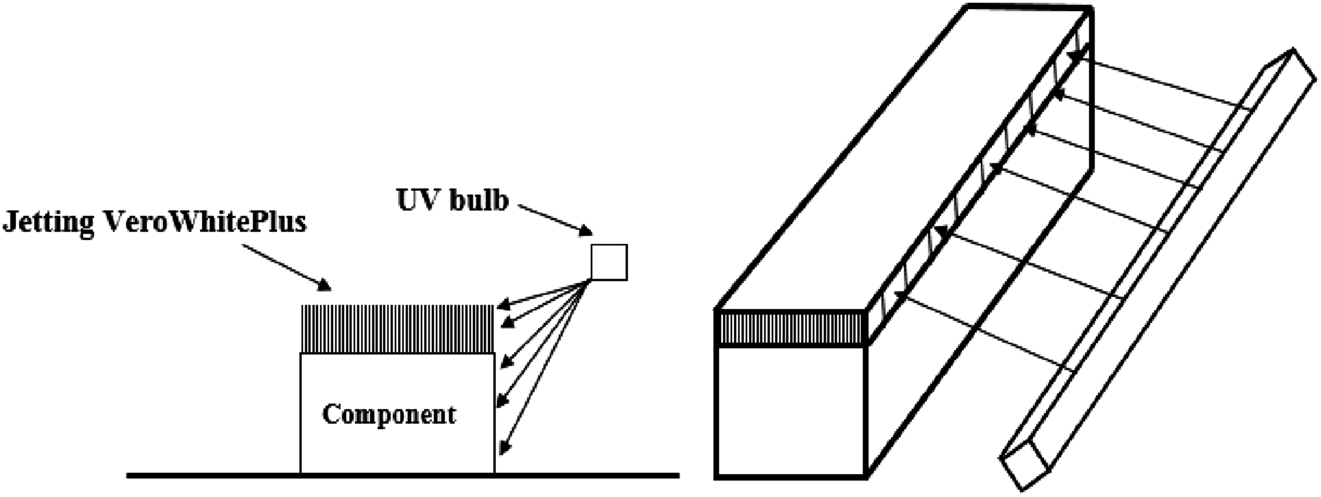
This non-uniform energy absorption, despite the uniform light source, is a key factor influencing the anisotropy observed in the mechanical properties of printed parts. PolyJet technology utilizes UV light to solidify each layer during printing. The UV bulbs in the printing machine emit light parallel to the jetting line of the print heads. As the print heads jet material, the edges of each layer, which are closer to the UV bulb, absorb more energy than the top surface, which is farther from the light source (refer to Figure 9).
27
This non-uniform energy distribution contributes to a variation in the mechanical properties across different regions of the printed part. Specifically, the areas of the sample that lie parallel to the XZ and YZ planes, as well as the vertically oriented sections, exhibit greater density and hardness, which correlate with enhanced tensile strength and overall mechanical resistance. Distribution of light energy for the surface of test samples at different distance.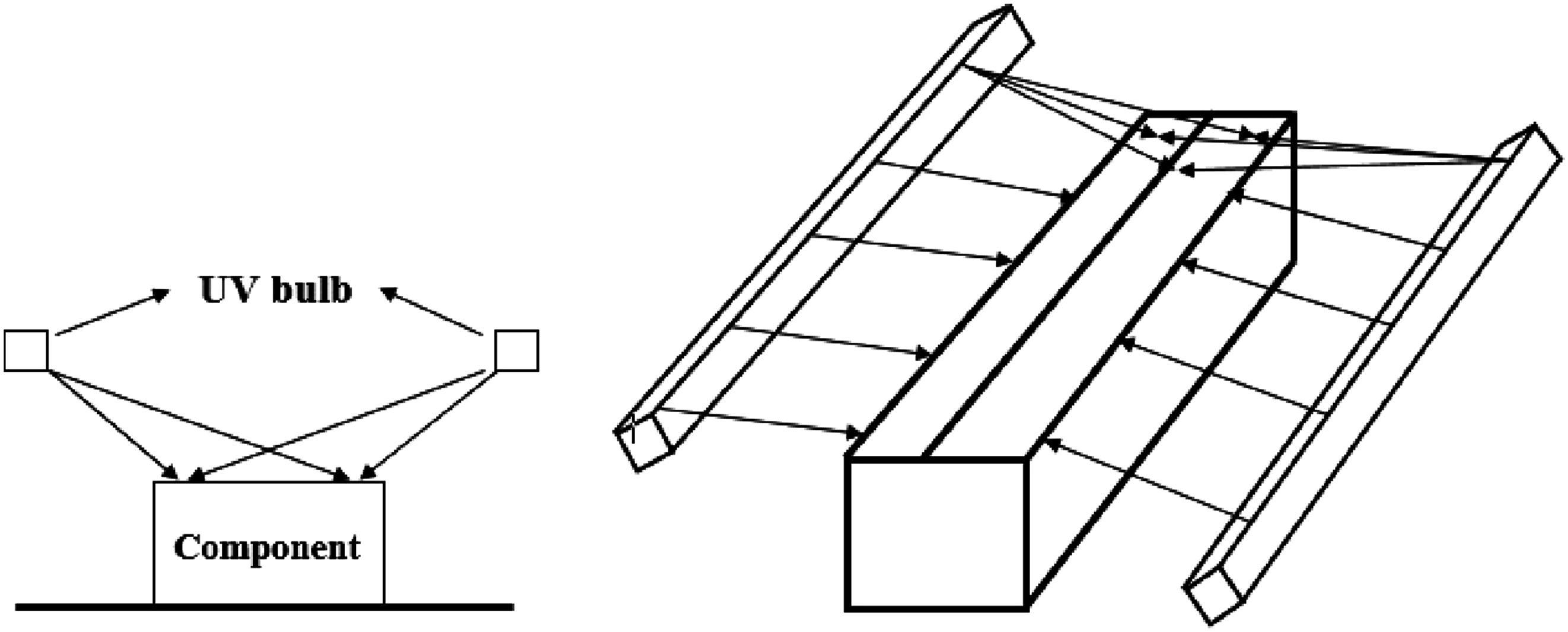
Figures 10 and 11 illustrate how this non-uniform energy distribution occurs during the printing process. Figure 10 depicts how the UV light illuminates both the top surface and the sides of the layer, leading to different levels of energy absorption. The sides of the layer, being closer to the UV light source, absorb more energy than the top surface.
28
This phenomenon results in denser, harder areas at the edges, which reinforce the material’s structural integrity and improve its mechanical properties. Figure 11 further emphasizes the effect of the UV light exposure, showing how the jetting heads’ orientation and movement result in more intense energy absorption along the sides of the printed layers.
29
Regions that received higher UV light exposure, particularly the edges aligned with the XZ, YZ, and vertical orientations, exhibited significantly higher hardness. This is consistent with the increased density and enhanced mechanical properties observed in these areas. The increased energy absorption at the edges strengthens the bonding between the layers, enhancing the material’s hardness and resistance to plastic deformation under stress. Distribution of light energy for the surface of test samples and lighted side. Distribution of light energy for the surface of test samples and lighted during the jetting.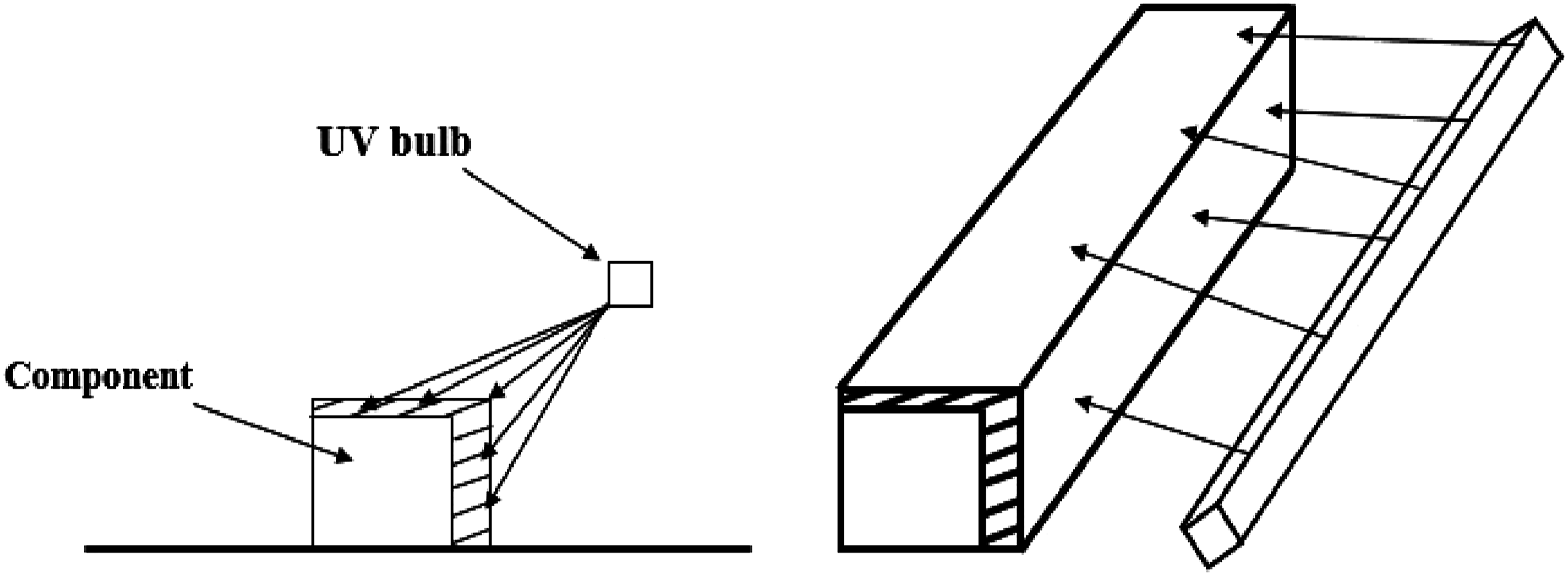
The surface roughness of the printed parts was also found to be affected by the energy distribution during printing. The regions with higher energy absorption, such as the edges exposed to greater UV light intensity, exhibited smoother surfaces. These areas with better-bonded layers and higher density showed lower surface roughness values. Conversely, areas receiving less UV exposure, such as the top surfaces and regions with lower density, had higher surface roughness. This difference in surface quality plays a role in the overall mechanical performance of the parts, as smoother surfaces are generally associated with better wear resistance and structural integrity under stress. 25 This phenomenon can be understood by considering the analogy of “many small sticks.” In orientations where layers are stacked vertically (XZ, YZ, and vertical), the tensile stress is more effectively distributed across the many layers, reinforcing the structure and enhancing its mechanical properties. In contrast, in orientations such as XY, YX, and flat, where the tensile force is applied perpendicular to the reinforcing edges, the mechanical properties are comparatively weaker. This is because the edge areas in these orientations do not benefit from the structural reinforcement provided by the vertically aligned layers, and thus the material’s strength is more dependent on the properties of individual layers rather than a combined reinforcement effect. The mechanical properties of PolyJet printed samples are heavily influenced by the orientation within the printer tray. The UV light’s varying exposure across different regions, particularly the edges, plays a pivotal role in determining the density, hardness, and roughness of these regions. 30 Consequently, parts with higher density, structural reinforcement along specific orientations, and smoother surfaces, such as XZ, YZ, and vertical, exhibit superior mechanical performance. The observed anisotropy can thus be attributed to the energy distribution during the printing process, which affects the bonding between layers, ultimately influencing the material’s hardness, surface quality, and mechanical strength. 31
While this study provides valuable insights into the influence of printing orientation on the mechanical properties of PolyJet 3D-printed parts, there are several areas that warrant further exploration. Future research could focus on exploring additional printing parameters, such as print speed, layer thickness, and UV light exposure intensity, to better understand how these factors affect material properties and part quality. Investigating other polymer jetting technologies like MultiJet Printing (MJP) and Material Jetting could also provide new perspectives on mechanical behaviors, bonding mechanisms, and material characteristics. Furthermore, the impact of printing orientation on complex geometries, such as thin walls, overhangs, and lattice structures, remains an area of interest, as these designs may exhibit different mechanical properties. Another promising direction is the investigation of long-term performance and fatigue behavior, including cyclic loading tests, to evaluate the durability and reliability of parts under real-world conditions. By delving into these areas, future research could optimize the PolyJet 3D printing process, expand its applications, and enhance the performance of 3D-printed components in diverse industries.
Conclusions
This study investigated the influence of printing orientation on the mechanical properties of 3D-printed parts fabricated using Polymer Jetting technology. Based on the analysis of tensile properties, hardness, surface roughness, and fracture behavior, the following conclusions can be drawn: (i) The printing orientation significantly impacts the tensile strength and hardness of the printed parts. Parts printed in orientations such as XZ, YZ, and vertical exhibit superior mechanical properties, including higher tensile strength and increased hardness, due to more effective stress distribution and reinforcement from the vertical stacking of layers. (ii) The printed parts show clear anisotropy in mechanical properties, with parts printed along orientations perpendicular to the layers (e.g., XY and YX) demonstrating lower strength and hardness compared to parts printed in orientations aligned with the layers (e.g., XZ and YZ). This anisotropic behavior is largely attributed to the non-uniform energy distribution during the printing process, which leads to varying layer bonding and material density. (iii) Surface roughness was found to be directly related to the energy absorption during the printing process. Areas receiving higher UV exposure (such as the edges of the layers) exhibit smoother surfaces, contributing to better surface quality, wear resistance, and structural integrity. Conversely, regions with lower UV exposure show rougher surfaces, negatively affecting the mechanical performance. (iv) The bonding between layers is a critical factor in determining the mechanical strength of the printed parts. Non-uniform energy distribution caused by the UV light intensity at different regions (e.g., edges vs top surface) results in variations in bonding strength, leading to differences in material density, hardness, and overall tensile strength across the part. (v) The fracture surfaces of the printed parts exhibited brittle fracture characteristics, with rough surface textures caused by localized pressures. The presence of air gaps and voids between printed layers weakened the material and contributed to its brittle nature. The void formation and weak bonding in the printing process reduce the material’s ability to withstand deformation under stress. (vi) The findings highlight the potential for optimizing printing parameters, such as print speed, layer thickness, and UV exposure intensity, to improve the mechanical properties and surface quality of PolyJet 3D-printed parts. Adjusting these parameters can lead to higher density, reduced anisotropy, and better bonding between layers.
Further research is needed to explore additional polymer jetting technologies, such as MultiJet Printing (MJP), and their influence on mechanical behaviors and bonding mechanisms. Additionally, the performance of printed parts under long-term cyclic loading and fatigue tests should be investigated to assess the durability and reliability of 3D-printed components in real-world applications. The printing orientation and energy distribution during the PolyJet printing process have a significant impact on the mechanical properties, surface quality, and fracture behavior of 3D-printed parts. By optimizing these factors, the performance and applications of PolyJet 3D printing can be enhanced, paving the way for its use in more demanding industrial applications.
Footnotes
Acknowledgments
The authors extend their gratitude to SRM University-AP, India for providing the necessary infrastructure and support to conduct this research.
Declaration of conflicting interests
The author(s) declared no potential conflicts of interest with respect to the research, authorship, and/or publication of this article.
Funding
The author(s) received no financial support for the research, authorship, and/or publication of this article.